1
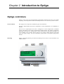
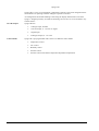
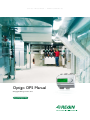
O P T I G O R E G U L A T O R – Optigo OP5 Manual ©Copyright AB Regin, Sweden, 2007 R E A D Y - S T E A D Y - G O ANSVARSBEGRÄNSNING All information i detta dokument har kontrollerats noggrant och bedöms vara korrekt. Emellertid lämnar Regin inga garantier vad gäller manualens innehåll. Användare av denna manual ombeds rapportera felaktigheter, tvetydigheter eller oklarheter till Regin, för eventuella korrigeringar i framtida utgåvor. Informationen i detta dokument kan ändras utan föregående meddelanden. Ingen del av detta dokument får återges eller överföras i någon form eller på något sätt, elektroniskt eller mekaniskt, för något som helst ändamål utan uttryckligt skriftligt medgivande från Regin. COPYRIGHT AB Regin. Med ensamrätt. VARUMÄRKEN Optigo är ett registrerat varumärke som tillhör AB Regin. Andra produktnamn som förekommer i detta dokument används enbart i identifieringssyfte och kan vara ägarens registrerade varumärken. DISCLAIMER The information in this manual has been carefully checked and is believed to be correct. Regin however, makes no warranties as regards the contents of this manual and users are requested to report errors, discrepancies or ambiguities to Regin, so that corrections may be made in future editions. The information in this document is subject to change without prior notification. No part of this document may be reproduced or transmitted in any form, in any fashion, electronically or mechanically, without the express, written permission of Regin. COPYRIGHT © AB Regin. All rights reserved. TRADEMARKS Optigo is a registered trademark of AB Regin. Some product names mentioned in this document are used for identification purposes only and may be the registered trademarks of their respective companies. mars 2007 Document number: X1nnn Document Revision: 2007-0-00 Table of contents Chapter 1 About this manual ..............................................................................................................4 Terms ..........................................................................................................................................................................4 More information ........................................................................................................................................................4 Chapter 2 Introduction to Optigo........................................................................................................5 Optigo controllers .........................................................................................................................................5 Chapter 3 Technical data ....................................................................................................................7 Chapter 4 Installation and wiring.......................................................................................................8 Installation.....................................................................................................................................................8 Wiring ............................................................................................................................................................8 Supply voltage.............................................................................................................................................................8 Inputs and outputs .......................................................................................................................................................9 Chapter 5 Control modes...................................................................................................................10 Control mode 1, Temperature control .......................................................................................................................10 Control mode 2, CO2 control ....................................................................................................................................12 Control mode 3, Humidity control ............................................................................................................................13 Control mode 4, Pressure control..............................................................................................................................14 Control mode 5, Pressure control with outdoor temperature compensation of the pressure setpoint........................15 Chapter 6 Display and encoder .........................................................................................................16 The Basic level..........................................................................................................................................................16 The 10-second level ..................................................................................................................................................17 Display symbols........................................................................................................................................................17 Chapter 7 Setpoint .............................................................................................................................18 Chapter 8 Configuration ...................................................................................................................19 Menus 1.0 – 5.0.........................................................................................................................................................19 Menu X.1 Output signals (Control mode 1 only), Transmitter range (Control modes 2, 3, 4 and 5)........................19 Menus X.2 Neutral zone (Control mode 1 and 3) .....................................................................................................20 Menus X.3 P-band.....................................................................................................................................................20 Menus X.4 I-time ......................................................................................................................................................21 Menu 1.5 Damper minimum position (Control mode 1 only)...................................................................................21 Menu 5.7 Start point for outdoor compensation (Control mode 5 only) ...................................................................21 Menu 5.8 Maximum compensation (Control mode 5 only) ......................................................................................21 Menus X.9 I/O...........................................................................................................................................................22 Menu OK ..................................................................................................................................................................22 Storage of settings .....................................................................................................................................................22 Chapter 9 Index .................................................................................................................................23 Chapter 1 About this manual This manual describes the controller Optigo 5. Terms A few terms used in this manual: FS Factory setting, the parameter value set on delivery More information • More information on OP5 can be found in: • Optigo controllers – Sales brochure for Optigo controllers • Optigo product instruction The information can be downloaded from the Regin website, www.regin.se. 4 Chapter 2 Introduction to Optigo Optigo controllers Optigo is a new series of pre-programmed, configurable controllers that can be set to handle everything from temperature control or humidity control to CO2 control or pressure control. OP 5 och OP 10 The Optigo series comprises two different types, OP5 and OP10. OP5 has 5 inputs/outputs and can be configured to control Temperature, CO2, Humidity or Pressure OP 10 has 10 inputs/outputs and can be configured to control Temperature (ventilation control with heating and cooling), Waterheated radiator-heating with outdoor temperature dependent control-curve or Tap hot-water control. OP10 als has a week-based scheduler. OP 10 is available in two versions, OP 10 with 24 V AC supply voltage and OP 10-230 with 230 V AC supply voltage. For more information, please refer to the separate Optigo OP10 manual. Mounting Optigo is designed primarily for DIN-rail mounting but can also be screw-mounted to any suitable surface. 5 Optigo OP5 Optigo OP5 is a new pre-programmed, configurable controller. It has been designed with the main intention of replacing a number of Regin’s Aqualine controllers. All configuration and normal handling is done using the display and the knob on the front. Optigo is designed primarily for DIN-rail mounting but can also be screw-mounted to any suitable surface. In- and Outputs Control modes 6 Optigo OP5 has • 1 analogue input, PT1000 • 1 universal input, 0…10 V DC or digital • 1 digital input • 2 analogue outputs, 0…10 V DC Optigo OP is pre-programmed with a choice of 5 different control modes: • Temperature control • CO2 control • Humidity control • Pressure control • Pressure control with outdoor-temperature dependent compensation Chapter 3 Technical data Supply voltage.................................................................................24 V AC ±15%, 50...60 Hz Internal consumption......................................................................................................... 6 VA Ambient temperature.....................................................................................................0...50°C Ambient humidity ................................................................................................Max 90% RH Storage temperature................................................................................................... -20...70°C Terminals..........................Disconnectable, so-called lift type for cable cross-section 2.5 mm2 Protection class................................................................................................................... IP20 Material casing ............................................................................................. Polycarbonate, PC Colour Cover ................................................................................................................................ Silver Bottom part................................................................................................................. Dark gray Weight ....................................................................................................... 215 g incl. terminals Dimensions......................................................... 123 x 123 x 60 mm (WxHxD incl. terminals) LVD, Low Voltage Directive This product conforms with the requirements of European LVD standard IEC 60 730-1 EMC emissions an immunity standard This product conforms with the requirements of European EMC standards CENELEC EN 61000-6-1 and EN 61000-6-3 and carries the CE mark Inputs AI ...................................................................................... PT1000-sensor. Range -30…+54°C AGND ........................................... Reference for AI and for UI when used as an analogue input DI ................................................................................................Closing potential-free contact DI+ .................................................................................................................. Reference for DI UI ...........................................................AI: 0...10 V DC or DI: Closing potential-free contact UI+ .....................................................................Reference for UI when used as a digital input Output AO .................................................................... 0…10 V DC; 8 bit D/A short-circuit protected Other data Display ............................................................... Numeric / graphic. Background illumination Accessories External temperature sensors................................................. TG-R5/PT1000, TG-KH/PT1000 CO2-sensor ...................................................................................CO2RT, CO2RT-D, CO2DT Humidity sensor .............................................................HRT, HRT250, HDT3200, HDT2200 Pressure sensor ..................................................... DMD, DTL-series, DTK-series, TTK-series The accessories are available from Regin. For more detailed information, see product sheets and instructions which are available at www.regin.se. 7 Chapter 4 Installation and wiring Installation Optigo can be mounted in a DIN-standard casing (minimum 7 modules), on a DIN-rail in a cabinet or, using a suitable front-mounting kit, in a cabinet door or other control panel. It can also be screwed to any suitable flat surface using the two screw-pockets provided. Ambient temperature: 0…50°C. Ambient humidity: max. 90 %RH, non-condensing. Wiring This section only describes general rules and technical limitations concerning the wiring. In chapter 5 there are specific wiring diagrams for the different control modes. Choose the one suitable for the application on hand. It is important to make sure that the wiring is correctly done, in accordance with the instructions given in this manual and in accordance with local legislation for this type of installation. 1 G 2 G0 24 V AC supply voltage 3 20 AGND Ref. for AO1 and AO2 21 AO1 0...10 V DC Output 22 AO2 0...10 V DC Output 41 DI+ Reference for DI1 42 DI1 Digital input 43 UI+ Reference for UI1 digital mode 44 UI1 0...10 V DC or Digital input 50 AGND Ref. for AI1 and UI1 analogue 51 AI1 PT1000 temp. sensor input Supply voltage 24 V AC ±15%, 50…60 Hz. 6 VA If the Optigo OP5 and active sensors and actuators connected to it share transformer, it is essential that the same transformer-pole is used as reference for all the equipment. Failure to do so will prevent the equipment from functioning as intended and may also lead to damages. 8 Inputs and outputs AGND All AGND terminals are interconnected and also connected to G0. Analogue input AI The analogue input must refer to an AGND terminal. The analogue input is for PT1000 temperature sensors only. Temperature range: -30…+54°C. Note: For temperatures below -9.9°C decimals will not be displayed. So make sure to differ between for example -2.7 (minus two point seven) and -27 (minus twentyseven). Digital input DI The digital input must refer to DI+ on terminal 41. The digital input may only be wired to voltage-free contacts. Any external voltage applied to a digital input may seriously damage the unit. Universal input UI The universal input can, depending on the choice of application, be made to act as either an analogue input or as a digital input. When used as an analogue input it is for 0...10 V DC input signals. When the Universal input is used as an analogue input it must refer to the AGND terminal or directly to G0. When used as a digital input it must refer to UI+ on terminal 43. It may then only be wired to voltage-free contacts. Analogue outputs Analogue outputs must refer to a AGND terminal or directly to G0. If the Optigo OP5 and active sensors and actuators connected to it share transformer, it is essential that the same transformer-pole is used as reference for all the equipment. Failure to do so will prevent the equipment from functioning as intended and may also lead to damages. 9 Chapter 5 Control modes Optigo can be configured to any one of the following control modes. 1. Temperature control. The temperature at the sensor is kept at the setpoint value by controlling the output signals on AO1 and AO2. A single PI control loop is used. 2. CO2 control. The CO2-value at the sensor is kept at the setpoint value by controlling the output signal on AO1. A single PI control loop is used. 3. Humidity control. The humidity at the sensor is kept at the setpoint value by controlling the output signals on AO1 and AO2. AO1 is used for humidification, AO2 for dehumidification. A single PI control loop is used. 4. Pressure control. The pressure at the sensor is kept at the setpoint value by controlling the output signal on AO1. A single PI control loop is used. 5. Pressure control with outdoor compensation. The pressure at the sensor is kept at the setpoint value by controlling the output signal on AO1. The setpoint is automatically adjusted according to the outdoor temperature. A single PI control loop is used. Control mode 1, Temperature control The analogue outputs can be configured to the following combinations: AO1 10 / AO2 1. Heating / - 2. Cooling / - 3. Heating / Cooling 4. Heating / 5. Cooling / Cooling 6. Heating / Damper 7. Cooling / Damper 8. Change-over/ Heating - (Seasonal change-over between heating and cooling) DI1, Start signal Normal control will only be activated when this input is activated, closed. When the start signal is deactivated the controller will set the outputs to 0. Note: This input must always be wired since it controls the starting and stopping of normal control. Universal input UI1, Change-over The change-over function will make a seasonal change of the function of the output signal on AO1. In summer the output will work as a cooling output and in winter as a heating output. This is used in applications (fan-coil units) where the same piping is used to transport hot water in the winter and chilled water in the summer. The universal input UI1 is used for the change-over function in alternative 8. Wire the input as a digital input using either a manual switch or a thermostat monitoring the supply water temperature to open/close the input. Open contact will give heating control and closed contact cooling control. Damper In applications with dampers it is often desirable to be able to set a minimum amount of fresh air. In the output alternatives 6 and 7 it is possible to set a minimum limit value to the damper output signal. The damper output will then not go lower than the set value during normal operation. On shut-down however the signal will go to zero. In the output mode heating – damper the damper will be fully open for temperatures higher than the setpoint. On increasing heat demand the damper will first close to the minimum value before the heating output starts to increase. In the output mode cooling – damper the damper will be fully open for temperatures lower than the setpoint. On increasing cooling demand the damper will first close to the minimum value before the cooling output starts to increase. G 1 G0 2 3 DI+ DI1 UI+ UI1 G0 G Y G0 G Y 20 AGND 21 AO1 22 AO2 41 42 43 44 AGND 50 AI1 51 24 V AC Start signal + - °C 11 Control mode 2, CO2 control CO2 CO2 D/ P The output signal will increase when the CO2-value rises above the setpoint value. The CO2-sensor must have a 0...10 V DC output for example: CO2RT, CO2RT-D Room sensors CO2DT Duct sensor The transmitter range cannot exceed 5000 ppm at 10 V DC output. DI1, Start signal Normal control will only be activated when this input is activated, closed. When the start signal is deactivated the controller will set the output to 0. Note: This input must always be wired since it controls the starting and stopping of normal control. G 1 G0 2 3 Damper DI+ DI1 UI+ UI1 G0 G Y 20 AGND 21 AO1 22 AO2 Frequency converter 12 + 20 AGND 21 AO1 22 AO2 41 42 43 44 AGND 50 AI1 51 24 V AC CO 2 transmitter G0 G Y Control mode 3, Humidity control RH RH max Humidification and dehumidification can be used simultaneously. A neutral zone can be set between humidification and dehumidification. The humidity transmitter must have an output signal of 0...10 V DC, for example: HRT, HRT250 or HRT350 Room humidity transmitters HDT2200 or HDT3200 Duct transmitters DI1, Start signal Normal control will only be activated when this input is activated, closed. When the start signal is deactivated the controller will set the outputs to 0. Maximum Limiting, RH Max When running humidification with the main sensor in the room it is sometimes desirable to have some sort of maximum limiting on the humidity in the supply duct. To create such a limiting function, place an on/off humidistat such as HMH in the supply air duct and wire it into the start signal circuit on DI1. The humidistat should be normally closed. Opening of the contact when the humidity rises above the set maximum value will force the humidity output to 0. G 1 G0 2 3 Humidifier Dehumidifier DI+ DI1 UI+ UI1 + + 20 AGND 21 AO1 22 AO2 41 42 43 44 AGND 50 AI1 51 24 V AC Start signal % RH G0 G Y Humidity transmitter HMH Max limiting humidistat 13 Control mode 4, Pressure control Fan GP Pump GP f /f f /f The output signal will increase when the pressure signal falls below the setpoint value. The pressure transmitter must have an output signal of 0...10 V DC, for example: DMD DTL-series DTK-series TTK-series Pressure ranges up to 500 kPa kan be set. Start signal Normal control will only be activated when this input is activated, closed. When the start signal is deactivated the controller will set the output to 0. Note: This input must always be wired since it controls the starting and stopping of normal control. G 1 G0 2 3 DI+ DI1 UI+ UI1 Frequency converter 14 + 20 AGND 21 AO1 22 AO2 41 42 43 44 AGND 50 AI1 51 24 V AC Start signal Pa G0 G Y Pressure transmitter Control mode 5, Pressure control with outdoor temperature compensation of the pressure setpoint. Fan f/f GT GP The output signal will increase when the pressure signal falls below the setpoint value. The setpoint value follows a settable pressure-to-outdoor temperature relation. The pressure transmitter must have an output signal of 0...10 V DC, for example: DMD DTL-series DTK-series TTK-series Pressure ranges up to 500 kPa kan be set. DI1, Start signal Normal control will only be activated when this input is activated, closed. When the start signal is deactivated the controller will set the output to 0. Note: This input must always be wired since it controls the starting and stopping of normal control. G 1 G0 2 3 DI+ DI1 UI+ UI1 Frequency converter + 20 AGND 21 AO1 22 AO2 24 V AC Start signal 41 42 43 44 AGND 50 AI1 51 Pa G0 G Y Pressure transmitter °C Outdoor temp sensor 15 Chapter 6 Display and encoder All setting and configuration is done using the display and encoder. The menu information on the display is organised in a tree fashion. Using the encoder you can move between menus, set values etc. In any of the configuration menus, a press on the encoder will activate change mode. You can then rotate the encoder button to move between choices or set values. A second pressing of the button will accept the choice. The menu system is divided into two levels: The Basic level and the 10-second level which contains all the configuration menus. The Basic level The Basic level comprises three sets of menu displays, the Base Display, the I/O Displays and the Setpoint Display. Base Display This is an example of the Base Display, the display that is normally shown when there is no operator activity. The upper line shows which control mode has been configured, in this case control mode 1, Temperature control. The bottom line shows the actual value of the main input parameter. There are bar-graphs showing the current output levels. In control mode 1 there are symbols showing how the outputs have been configured (Heating, Cooling, Damper or Change-over). I/O When the Base Display is shown, by twisting the knob counter clockwise until the text I/O is displayed and then klicking on it, you can gain access to a menu where you can look at the values and states of all inputs and outputs. To exit this menu again, klick on the knob and then twist the knob clockwise and you will be returned to the Base display. Setpoint When in the Base Display, a press on the encoder button gives direct access to the Setpoint menu. See chapter 7 Setpoint. 16 The 10-second level This level is reached from the Base Display by depressing and holding the encoder button for 10 seconds. The 10-second level holds all the configuration menus. See chapter 8 Configuration. Note: The controller must displat the Base Display when pressing the encoder knob to reach the 10-second level. Display symbols Outdoor compensation configured Configuration level Menu number AO1 Graphic output signal Control mode 1 only Temperature control Bargraph AO1 output level Menu holds changable values Bargraph AO2 output level Active 0...10V input signal AO2 Graphic output signal Control mode 1 only 17 Chapter 7 Setpoint The setpoint menu is normally accessed from the Base Display by a klicking on the encoder knob. If you wish to change the displayed value, klick on the knob again and the change indicators will start to flash to show that you are now in change mode. Twist the knob, clockwise to increase the value, counter-clockwise to decrease. In applications with active input signals (control modes 2, 3, 4 and 5) the setpoint cannot be set higher than the value corresponding to 10 V DC input signal. When the desired value is shown, klick on the knob to acknowledge. To return to the Base display, twist the knob. For configurations involving a single output signal the setpoint is the starting point for the output signal. For configurations involving two diverging output signals with neutral zone (heating – cooling or humidification – dehumidification) the setpoint is placed in the middle of the neutral zone. For configurations involving two outputs without neutral zone (heating – heating, cooling – cooling, heating – damper or cooling – damper) the setpoint value is the starting point for the first sequence (Y2) 18 Chapter 8 Configuration All the configuration menus lie in the 10-seconds level. This level is accessed from the Base Display by pressing and holding the encoder button for 10 seconds. There are numerous configuration menus covering all available options and combinations. In some cases, making a certain choice in one menu will mean that you will only see certain other menus. For example, the menu for setting the damper minimum limit is only shown if you have configured AO2 to be a damper control output. Menus 1.0 – 5.0 In the first set of configuration menus you choose which of the five control modes you wish to run. The upper text row, the lower text row number and the first digit in the menu-number show which control mode is at hand. 1. Temperature control 4. Pressure control 2. CO2-control 3. Humidity control 5. Pressure control with outdoor compensation Menu X.1 Output signals (Control mode 1 only), Transmitter range (Control modes 2, 3, 4 and 5) Control mode 1. For temperature control there is a choice of 8 different output signal combinations. Select one fitting the application on hand. AO1 1. Heating 2. Cooling 3. Heating 4. Heating 5. Cooling 6. Heating 7. Cooling 8. Change-over / / / / / / / / / AO2 Cooling Heating Cooling Damper Damper - Output symbol \ / \/ \\ // \/ \/ Graphic symbol 19 For each alternative the number representing it is shown along with a graphic symbolisation of the output signals and also a symbol next to the bar-graph for each output. Output signals, graphical Control mode 1 menu 1 Example, Menu 1.1 AO1 Heating AO2 Cooling Temperature control with output alternative 3 Heating/Cooling Output alternative 3, Heating/Cooling Control modes 2, 3 4 and 5 For control modes using active 0…10 V DC transmitters you need to scale the input signal. For example, if you have a pressure transmitter that will give a 0…10 V output for a pressure range of 0 to 5000 Pa, set the value to 5000 Pa. Note that for pressure transmitters the pressure, depending on the range, may be given in Pa or kPa. Ranges up to 500 kPa can be set. Also, not all values between 0 and 500 kPa kan be set since this would involve a great amount of twisting on the encoder. In the low ranges the values are close but become increasingly further between as the values go up. For CO2 transmitters the range is set in ppm and for humidity control in % RH. Example, Menu 2.1 CO2-control with input signal 0…10 V for CO2 value 0…2000 ppm. Menus X.2 Neutral zone (Control mode 1 and 3) In two control modes involving diverging output signals (heating – cooling or humidification – dehumidification) you can set a neutral zone between the outputs. The setpoint will be placed at the middle of the neutral zone. Menus X.3 P-band Here you set the P-band (Proportional band) The P-band unit depends on the choice of control mode. The P-band is the control offset necessary to drive an output signal from 0 to 100%. In configurations involving two outputs the same P-band applies to both outputs. 20 Menus X.4 I-time Here you set the Integration time (Reset time). If the I-time is set to 0 the integration function is disabled and the controller will act as a P-controller. Menu 1.5 Damper minimum position (Control mode 1 only) If you in menu 1.1 have configured output AO2 to be a damper, alternative 6 or 7, you can set a minimum value to the damper signal. . The damper output will then not go lower than the set value during normal operation. On shut-down however the signal will go to zero and fully close the damper. Menu 5.7 Start point for outdoor compensation (Control mode 5 only) S.P is the outdoor temperature at which the setpoint compensation starts. At temperatures higher than S.P the normal setpoint value is maintained. When the outdoor temperature falls below S.P the pressure setpoint will change linearly on decreasing temperature to reach the pressure set by SPL in menu 5.8 below at an outdoor temperature of -20°C Menu 5.8 Maximum compensation (Control mode 5 only) SPL is the setpoint to be held at an outdoor temperature of -20°C. The setpoint shift starts when the outdoor temperature falls below the value set in S.P in menu 5.7 above and will change linearly with decreasing outdoor temperature reaching SPL when the outdoor temperature is -20°C. Note that SPL is not a setpoint shift value to be added to the normal setpoint value but the actual setpoint value at -20°C outdoor temperature. Setpoint 300 SPL 200 -20°C 10°C S.P Outdoor temp Example: With an ordinary setpoint of 300 Pa, a starting point S.P of +10°C and a SPL of 200 Pa at -20°C you get the following setpoint-to-outdoor temperature relation 21 Menus X.9 I/O After the last configuration menu there is a menu where you can look at the actual values of all the inputs and outputs. This menu can also be accessed directly from the Base Display by twisting the encoder knob counter clockwise and then pressing. See chapter 6. Menu OK Last of the configuration level menus is the OK-menu. To leave the configuration level, go to this menu and press the encoder knob. On exit from the configuration level you will be returned to the Basic level. There is also a time-out function that will automatically exit the configuration level after 5 minutes of inaction. Storage of settings All configuration settings become valid as soon as they are entered by klicking the encoder knob. They are however not written to the flash memory until you exit the configuration level either via the OK menu or via the time-out function. To exit the configuration level without saving the changes to flash memory, cut the supply voltage when still in the configuration level. All values will be kept as they were before you entered the configuration level. Reset to factory setting The OP5 can be reset to factory settings by configuring Humidity control (mode 3) and setting the P-band to 99. Then cut the power supply. When power is reapplied all configuration settings will be reset to factory setting. 22 Chapter 9 Index I-time ...................................................................................21 1 10 second level.................................................................... 17 L LVD.......................................................................................7 A Analogue inputs .................................................................... 9 Analogue outputs .................................................................. 9 B Basic level ........................................................................... 16 C Change-over ........................................................................ 11 Configuration ...................................................................... 19 Configuration level.............................................................. 17 Control modes ....................................................................... 6 1, Temperature control.................................................... 10 2, CO2control .................................................................. 12 3, Humidity control......................................................... 13 4, Pressure control........................................................... 14 5, Pressure control with outdoor temperature compensation of the pressure setpoint ........................ 15 D Damper limiting ............................................................ 11, 21 Digital inputs......................................................................... 9 Display and encoder ............................................................ 16 E EMC...................................................................................... 7 I Inputs and outputs ............................................................. 6, 9 Analogue inputs ................................................................ 9 Analogue outputs .............................................................. 9 Digital inputs .................................................................... 9 Universal inputs ................................................................ 9 Installation............................................................................. 8 M Menu Configuration ..................................................................19 I/O .............................................................................16, 22 OK...................................................................................22 Setpoint .....................................................................16, 18 Mounting ...............................................................................5 R Reset time ................................................................See I-time S Setpoint................................................................................18 Start signal ................................................... 11, 12, 13, 14, 15 Supply voltage .......................................................................8 T Technical data........................................................................7 Inputs.................................................................................7 Outputs ..............................................................................7 U Universal inputs.....................................................................9 V,W Wiring....................................................................................8 Wiring diagram Control mode 1................................................................11 Control mode 2................................................................12 Control mode 3................................................................13 Control mode 4................................................................14 Control mode 5................................................................15 Wiring diagram, general ........................................................8 23 R E G I N – T H E C H A L L E N G E R I N B U I L D I N G A U T O M A T I O N AB Regin Huvudkontor, Marknadsföring, Försäljning och Logistik Box 116 Telefon: + 46 (0)31-720 02 00 E-mail: 428 22 Kållered Fax: Websida: www.regin.se + 46 (0)31-720 02 50 [email protected] Försäljningskontor Frankrike Försäljningskontor Singapore Försäljningskontor Hong Kong Regin Control SARL Regin Controls Asia Pacific Pte Ltd Regin Controls Hong Kong Limited 5 Rue Regnault 66 Tannery Lane, 2901 EW International Tower FR-93500 Pantin, France #03-04 Sindo Building, Singapore 347805 120 Texaco Road, Tseun Wan, Telefon: +33 (0)1 41710034 Telefon: + 65 6747 8233 NT, Hong Kong Fax: Fax: Telefon: + 852 2407 0281 Websida: www.regin.fr + 65 6747 9233 E-mail: [email protected] Websida: www.regin.com.hk Websida: www.regin.com.sg wendelbo.com 2006 +33 (0)1 41714646