1
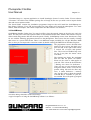
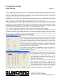
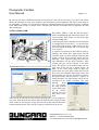
Photoplotter FilmStar
User Manual
Page 1 / 8
0.1 Overview
Please address any inquiries related to the photoplotter hard- or software to your local dealer first. The Photoplotter software is subject to copyright. All information enclosed here is subject to change. This manual
was last updated on 07. Dec. 2004
FilmStar is a small, inexpensive raster photoplotter that exposes the film by a diode laser. The film is mounted to a rotating drum. The laser light moves step by step in parallel to the drum axis. The unit has an external power supply and is computer controlled.
FilmStar uses films sensitive to red light, as standard in photoplotting industry. These films come in sheets
or on rolls and usually have 0.1 or 0.18 mm thickness. Suppliers are e. g. Agfa, Kodak, Fuji. We supply 0.1
mm thick sheets cut to size ready for use on FilmStar. As usual these films require a darkroom where they
go through a standard development and fixation procedure. The darkroom needs a special green safe-light illumination.
The extent of delivery of FimStar comprises 3 software programmes. The first,. Gerb2Bitmap, serves for
data preparation. The second, Run_Plotter_USB, takes the so prepared data to control the plotter via the parallel port of your PC. The third application supplied is ViewMate, a Gerber viewer and aperture converter
tool that is supplied for free.
The most common data format for use on FilmStar is Extended Gerber (RS-274X). If this is not available
standard Gerber (RS-274D) may be used. In this case a built-in aperture converter helps transform the aperture tables of all common CAD and CAM software into a standard format suitable for use with Gerb2Bitmap. This software exports the bitmap data in a proprietary FPF format for use on the plotter driver software. For data inspection purposes it can as well export BMP in a 250 dpi resolution. We also include on the
CD a program called FPF-Viewer that allows to inspect the contents of FPF files. Further use of the Gerb2Bitmap software is i. e. to mount several layouts on one sheet of film, or creation of step and repeat artwork. Optional software is required for conversion of Postscript data.
The Run_Plotter_USB software controls the photoplotter via USB port. It reads bitmap data in the above
mentioned FPF format or, at user´s choice, in Windows BMP format. In Run_Plotter_USB you may select
the output resolution as well as positive or negative, direct or mirrored output.
0.2 Technical Data
Maximum film size:
Maximum plot area:
Resolution X / Y:
Speed:
Light source:
Data format Import:
Aperture table input:
Aperture converter input:
Plotter size:
Weight:
Power supply:
System requirements software:
400x320 mm (L x W)
380 x 300 mm
select 508, 1016, 1355, 1625, 2032, 2710, 4064, 8192 / 8000 dpi
13 mm of film width per minute at 1016 dpi
Laser diode 670 nm (red)
Gerber, Extended Gerber, Hi-Res. BMP, FPF
CAM350, GC-CAM, IsoCAM, Lavenir,
PADS, EAGLE, OrCAD, Protel, PCAD and others
700 x 350 x 200 mm (L x W x H)
approx. 24 kg
External power supply 110V-240V / 24V-2A
Pentium PC, Windows 98 or higher, 15O MB free Hard disk.
Computer speed has influence on plotting speed.
Bungard Elektronik GmbH & Co. KG ·
Rilke Str. 1 · D-51570 Windeck/Sieg
Tel.: 02292 5036 Fax: 6175 E-mail: [email protected]
Photoplotter FilmStar
User Manual
Page 2 / 8
1. FilmStar Set-Up and first test
1.1 Dark room
All feeding or removing of film from the photoplotter, as well as the subsequent development and fixation,
require dark room conditions and a special green safe light. Install the unit in an appropriate room together
with trays or tanks one each for development, fixation and rinse. In this room you will further need a main
supply for the plotter and the safe light. Further the USB cable coming with the plotter must be run out of
this room to the place with the computer.
We recommend vertical mounted tanks with cover for the chemical processing. These need little installation
footprint and the liquids have a small surface compared to their volume, which increases their life time. Further, vertical film handling has the big advantage that no air bubbles can stay underneath the film and spoil
development.
1.2 Set Up
The front panel of the unit has LEDs as well as a switch labelled Auto/Man. The power-on switch is on the
left side of the unit. At its rear there is the input connector for the external power supply and the USB port.
Place the photoplotter in the dark room and connect the power supply to mains. Do not yet turn on the power
supply and the plotter. Connect the USB cable and check if the Auto/Man. switch is in Auto position.
Connect the USB cable to the computer outside the dark room and start the computer. It will recognize a
new device on the USB port. Do not allow Windows to search the drivers by itself, but specify the CD home
directory as the place where to look for the installation files. You can ignore messages that say this driver
was not certified. Next, install the software from the CD coming with the plotter. The Set-up programme can
be found in the Install directory on the CD. The installation procedure will be explained later in more detail.
The first test of the unit will work with no special software configuration, but for later use under real conditions, individual configuration data need to be entered in the Setup / Setup table and the Light menu of the
Run_Plotter software. These information are supplied on a data sheet or floppy disk coming with the unit.
Please refer to page 9 of this manual for details.
You may now turn on the plotter. You will hear a cooling fan and you will see the green LED blinking. The
laser head will move to the home position with a little humming noise.
1.3 Test run
You will need some adhesive tape to mount the film on the drum. We suggest you use white paper tape
(painter's utilities), as this white tape can be best seen in the dark room light and it can easily be cut off the
roll by hand.
Enter the dark room, turn the green safe light on and make sure there is no extra light from outside dropping
in. Open FilmStar´s lid. You will see the drum. Turn it by hand until the white arrow on the drum faces the
white arrow on the left of the drum housing. Take a sheet of film from its box and tape the upper end to the
drum in a way that the tape sits about 20 mm on top over the arrow.
The emulsion side of the film must be facing the drum. Films coming on rolls are already wound accordingly. Under the green light, the emulsion side of the film normally looks gray, the top side is darker.
There is another white arrow on the lower part of the drum housing that you should use for lateral positioning of the film. After you fixed the upper edge of the sheet, turn the drum by hand and sweep over the sheet
so it goes tightly on the drum. It is important that the sheet edges are parallel to the drum axis and that the
upper and the lower sheet corners are facing each other, i. e. the film is not twisted, else the image will be
distorted or the line edges will not be sharp. (Mounting films correctly will need some practise.)
Bungard Elektronik GmbH & Co. KG ·
Rilke Str. 1 · D-51570 Windeck/Sieg
Tel.: 02292 5036 Fax: 6175 E-mail: [email protected]
Photoplotter FilmStar
User Manual
Page 3 / 8
In that state use adhesive tape to fix also the lower end of the film to the drum. Finally, it is very important
that you turn the drum further to the starting position with the two white arrows in one line.
Close the lid, re-pack all film material into a safe box and leave the dark room. You may now start a first test
plot of a test grid in a quick step-by-step procedure. (A more detailed explanation of the included software
follows later in this manual.)
Start the Run_Plotter_USB software, go to the Setup / Generate Grid menu. For the Grid parameters enter 5
for the Drum axis, 36 for the drum circumference and 5 for the Line width. Press OK. A grid of 5 cm width
and 30 cm height will be created ready to plot. Click the triangular start button from the menu symbols or
press the F5 function key (see also tolls menu). In the next menu you can select the output resolution. The
other entries will be explained later. Click the Plot button to start plotting.
The drum rotation starts slowly and noisy (due to stepper motor
resonance). After reaching the nominal speed the computer initiates the plotting. The LED marked Laser
lights/blinks according to the on/off condition of the laser head. The computer screen shows a progress indicator. You may stop the plotter immediately by pressing the square STOP button (or the F6 function key).
After each stop of the plotting, either by program or user, the laser head will go to the home position. You
should wait until this home run finished. If you try to start a new plot too early the machine will not be able
to communicate with the computer.
After the test job was finished you may return into the dark room and develop the film as explained in the
next chapter.
Remark: Films from different manufacturers show different light intensity. It is therefore possible and even
necessary to adapt the light intensity. So if your first test plot shows poor line blackness this will be overcome after you processed the setup explained later in this manual. For that purpose the program's tool menu
contains an item "plot lightbar (multi resolution)".
Keep the drum surface clean and dry. In order to remove possible residues of the adhesive tape please use a
soft cloth with a liquid cleaner, like Isopropylic alcohol. Please do not use spray cleaners.
During the plotting process the film is exposed to laser light. This light can injure the human eye. Never
look into the laser beam.
Bungard Elektronik GmbH & Co. KG ·
Rilke Str. 1 · D-51570 Windeck/Sieg
Tel.: 02292 5036 Fax: 6175 E-mail: [email protected]
Photoplotter FilmStar
User Manual
Page 4 / 8
2. Film development and fixing
In this chapter we assume that you are using the film and chemicals that we supplied and that you are treating the film in the dark room also made by us. If you are using other consumables or equipment you will
have to adapt to your working conditions the instructions given here below.
The setup concentration of the developer and fixer concentrate are given on the jerrycans: Dilute one part of
concentrate in 2 parts of water. As a precaution, if your tap water is very hard please use deionized water.
The three vertical tanks in our dark room take 9 litres each, so you will need each 3 litres of concentrate and
6 litres of water at room temperature.
The fixer goes in the first tank from the front, the middle tank takes the rinse water and the last tank is to be
filled with developer. Be careful when filling in the liquids. The developer will be destroyed if fixer drops
in. Please keep all tanks closed by the lids. The water in the middle tank will need to be replaced frequently.
Components of the film emulsion will leave pasty residues in this tank. To empty the tanks, take the flexible
hose from the holder, close the opening by your thumb, put the end over the container where you want to
drain the liquid in and release the thumb. Wash all tanks with water and make sure there are no residues sitting on the walls.
The procedure to develop a film exposed on FilmStar takes not more than a minute. If you do not like to
touch the liquid by hand (wear thin Latex gloves) you should use a film clamp. Especially big sheets of film
tend to stick to the tank wall. To avoid this, try to handle the sheet so that it goes in the tank in an S shape.
This little disadvantage in handling is minor compared to the advantage that there will be no air bubbles at
all under the film surface, as known from horizontal development trays. Moreover, the tank offers only a
small liquid surface to the air, so that the destructive oxidization of the developer will be delayed..
After exposure a short rinse is sufficient. In the fixer the film will mostly be clear after 30 seconds. It is
good practise and gives better long term stability, though, to keep it in the fixer for double the time. Rinsing
after fixing is highly important. Finally, to dry the film, put it to the dark room wall and wipe the first side
with a smooth fuzzle-free paper tissue. Remove the film, dry the wall, reverse the film and wipe the second
side. Repeat the procedure with a fresh tissue. You may also profit from a hot air dryer. A well dried film
looks fully transparent. Rests of opaque, bluish colour indicate insufficient drying. The ambient humidity
and the drying grade of the film will highly affect the film precision!
As mentioned, the developer will oxidize when in contact with air. It will take a brown colour and cannot
blacken the film sufficiently any more. Test: Expose a piece of film for 2 seconds to normal daylight. After
max. 1 minute of development at ambient temperature the film must be entirely black opaque. If this is not
the case the developer must be exchanged. If you use the tank lid and take care not to pollute the developer
it will have a life time of more than 6 months. For frequent use the developer may be replenished with concentrate that you add in portions. The life time of the fixer mostly depends on the throughput. The time
needed to clear the film will be longer with increasing use. Attention: The fixer contains silver and must be
recycled! Safety data sheets for the developer and fixer concentrates are available. These are actually no
dangerous goods for road transportation.
3. Software
3.1 Overview
The software comes on a CD that contains the folders Install, Manual, Util and Viewmate. The Manual
folder contains this instruction as a PDF file.
Bungard Elektronik GmbH & Co. KG ·
Rilke Str. 1 · D-51570 Windeck/Sieg
Tel.: 02292 5036 Fax: 6175 E-mail: [email protected]
Photoplotter FilmStar
User Manual
Page 5 / 8
\ViewMate\Setup is a separate application to install Pentalogix' (former Lavenir) Gerber Viewer software
"Viewmate". We add it to the FilmStar package free of charge for the case you need a tool to inspect Gerber
data and convert aperture tables.
The \Install folder contains the installation programme Setup.exe that will install the Gerb2Bitmap.exe,
Run_Plotter_USB.exe, View_FPF and associate files. Run_Plotter will control the photoplotter. Two more
folders, Mark and Sample, will contain sample data after the software was installed.
3.2 Gerb2Bitmap
Gerb2Bitmap handles Gerber data. You may load files, place the artwork image on the plot area, and view
them. You may also convert the aperture tables of non-extended Gerber data. Further, this software can panellize boards and generate drill data from the panels. Finally, Gerb2Bitmap creates raster data that are ready
for use with the following programme that drives the photoplotter. These raster data are actually a bitmap
that comes in a special FPF format. There is an additional output possibility for 250 dpi Windows BMP
files, so that you can inspect the conversion results by double clicking the BMP file in Windows Explorer.
The programme screen is divided in the
menu bar, the icon bar, the (dark gray)
plot area and, at the right of the screen,
a vertical list of layers and aperture
files. The icons have bubble help coming up if you place the mouse cursor
over them.
The plotting area shows the maximum
film size that the plotter can handle.
Please set the value to what applies to
your unit. This is done in the Preference
/ Plotting area menu. In Preference /
Units you may set your preferred measuring unit (metric, inch). A last, but important setting that must be done only
once, is under Preference / memory
size. Set this value to about the amount
of RAM that is available on your PC,
less 20 MB. This will speed up program
execution during calculation of the raster image.
A typical sequence of using the Gerb2Bitmap software is as follows:
Bungard Elektronik GmbH & Co. KG ·
Rilke Str. 1 · D-51570 Windeck/Sieg
Tel.: 02292 5036 Fax: 6175 E-mail: [email protected]
Photoplotter FilmStar
User Manual
Page 6 / 8
1. Job / Import Master Gerber opens a file selector that allows to import Gerber files, either standard or extended. In a first approach we assume you have selected a file in Extended Gerber format. A rectangle
comes up in the upper right corner that corresponds to the artwork in size and orientation. You drag this
rectangle versus the plot origin in the upper left corner.
Repeating this step you may arrange several layouts on the plot surface. Try to right click the red rectangle
with the mouse: This will give a pop up menu that allows to position, lock, unlock and delete the particular
image. If you have several images on the screen the one in red colour is the active one.
Some programming reasons require that the assignment of the X and Y axes on the screen look different
than on the photoplotter: The plot image is both mirrored and twisted by 90 degrees. That causes that the
direction of the drum circumference shows from the left to the right, and the laser head movement is on an
axis showing vertically on the screen. For maximum execution speed you should try to arrange all artwork
so that most data is in the direction of drum rotation, say horizontally on the screen.
2. Job / Preview opens a preview window to show you the total of all layouts that you loaded.
3. Job / Export Fotoplotter File (FPF) creates the raster data in an internal format called FPF. These data are
written to a file of your choice and that can later be used by the Run_Plotter software. In this menu you select also the resolution (dpi) in which data will be converted. Please note that high dpi settings give huge
files. Also there is a limitation in Windows 98 (GDI memory) that could spoil the FPF file contents at a too
high dpi setting. Windows XP should not have that limitation.
If you have no Extended Gerber files you need to specify the measuring
unit and the zero suppression for each Gerber file. This is done in Preference / Data Format. Second, and again for all Gerber files, you need to
load an appropriate aperture file. This is done from the Job / Import Apertures menu. A dialogue window will show up that allows to select the type
of aperture file to load, and allows to select to use an aperture converter.
The aperture files from CAM350, GC-CAM or IsoCAM are supported directly. (You may also use the external ViewMate software to convert aperture files to the Lavenir format .ENV.)
The aperture converter built into Gerb2Bitmap will take all necessary information automatically. You just press "Guess format" and "Start". To
quit the converter, press ESC.
The name of the aperture file will show in the
column right to the one with the name of the Gerber
file. Each Gerber file needs its own aperture table. If
a Gerber image was removed from the plot area, the
associate aperture table will be removed as well. Using standard Gerber files with no or wrong aperture
tables gives faulty results.
You may view and edit the aperture file assigned to
the actual layer: Select Preference / Aperture table.
This menu also allows to create a new table. Anyhow, each entry needs to have the right shape and
size information typed in. After you clicked on Save
and named the file this will be written to disk as a
Lavenir aperture file with the ENV extension.
Bungard Elektronik GmbH & Co. KG ·
Rilke Str. 1 · D-51570 Windeck/Sieg
Tel.: 02292 5036 Fax: 6175 E-mail: [email protected]
Photoplotter FilmStar
User Manual
Page 7 / 8
By the way, the above mentioned column of several layers will only be necessary if you have one Gerber
master file and want to create a set of films in the same spacing and arrangement, like a four colour film set
for publishing / printing. The Tool/Panelize function will then handle all associated Gerber files according
to the Master file on layer 1 and the Tools / Panelize drill function will further allow to duplicate the drill
data accordingly.
3.3 Run_Plotter_USB
Run_Plotter_USB.exe reads the FPF file generated in Gerb2Bitmap and controls the plotter. Except from FPF, Run_Plotter can also read highresolution BMP files.
Controlling the plotter includes also the individual configuration of each unit, i. e. in terms of the
laser head's light intensity. Additionally, you may
choose to mirror the output and / or to create negative artwork.
A sequence of operation in this software starts by
loading a file via the File / Open menu. The file
selection allows to select from the different data
format. A file in the special FPF format will additionally show a preview image and will contain information on the input resolution. After
clicking OK you will be returned to the main
menu. The picture of the loaded image will appear (only if the file size is below approx. 14
MB). As the raster image might be quite big
please allow for a little time to load data. To continue, press the triangular Start button. In the following menu you may set the output resolution,
the light intensity and the positive / negative or
mirrored output. The light setting will be pre-set
according to the output resolution. The entry
Plotting
speed
Lo / Hi controls
the drum rotation
speed. Putting this
on Hi reduces
plotting time, but
may cause vibrations.
There will be an indication on the estimate plotting time. If your computer is
very slow, the displayed time will be different from the time actually needed.
Click on Plot to start the plot. It may take several seconds until the drum has
reached nominal speed. There will be a progress indication on the screen.
Bungard Elektronik GmbH & Co. KG ·
Rilke Str. 1 · D-51570 Windeck/Sieg
Tel.: 02292 5036 Fax: 6175 E-mail: [email protected]
Photoplotter FilmStar
User Manual
Page 8 / 8
The Run_Plotter software needs one initial set-up in order to prepare it for use with the individual machine.
This set-up covers the light intensity in relation to the output resolution as well as certain correction values.
The configuration data come with the plotter on a sheet of paper and/or on a floppy disk.
The light intensity settings are coarse proposal values only. They will vary with the
type of film and developer that you use, so you have to adapt them to your specific
using conditions by test. The Auto / Manual switch that was mentioned in the beginning helps to do this light test. If you put this switch to Manual the laser head will
not return to the home position but will stay where it was after the last plot. In this
way you may create several test images with different light settings on one piece of
film. Too poor light intensity will
create gray instead of black
areas. Too strong exposure will
expand the size of fine lines and
may create gray shades at the
edges of black areas. To assist in
finding the right light intensity
for several resolutions by one test, choose the menu from
tool / plot light bar (multi resolution). You may enter 4
different resolutions with different initial settings. Step
is the value to increase the settings from one step to the
next. A sample of a film that was made with this function should be included with the plotter and is an indication for the settings that you should use together with the films and chemistry that we offer.
The Setup / Table menu contains the main
configuration settings. Important values are
the "corrected drum diameter" and the
"screw error on 300 mm". Both values are
contained on the configuration sheet we supplied. If your individual unit needs other
special settings you may find them on a
floppy disk that we added. In this case,
please import the file xxx-yy.phs via the
Setup / Import table menu. Xxx Stands for
the plotter serial no.
If there are very special requirements on the
plotter precision - and suitable measuring
devices assumed - the plotter can be calibrated both in the drum and spindle direction.
For this purpose the Tool / Generate Test
Grid menu creates a grid with lines each 10 mm. You may measure the actual line spacing and enter the results into the columns "Drum linearity" and "Screw linearity". As you will rarely need these micrometer
range corrections we are not going more into details at this point. If you need further assistance please call
our support.
© 2004 Bungard Elektronik
Bungard Elektronik GmbH & Co. KG ·
Rilke Str. 1 · D-51570 Windeck/Sieg
Tel.: 02292 5036 Fax: 6175 E-mail: [email protected]