1
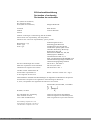
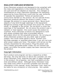
MEGA CCD MANUAL user manual
http://www.manuallib.com/file/2590440
From ManualLib.com
ManualLib.com collects and classifies the global product
instrunction manuals to help users access anytime and
anywhere, helping users make better use of products.
Home: http://www.manuallib.com/ Chinese: http://www.shuomingshuku.com/
This Manual: http://www.manuallib.com/file/2590440
CCD MANUAL
USERS GUIDE
Mega Electronics Ltd.,
Mega House, Grip Industrial Estate,
Linton, Cambridge.
England
CB1 6NR
Telephone: +44 (0) 1223 893900 Fax: +44 (0) 1223 893894
email: [email protected]
Web: www.megauk.com
This Manual: http://www.manuallib.com/file/2590440
This Manual: http://www.manuallib.com/file/2590440
CCD
Manual
Contents
Page
Security Information
Declaration of Conformity
0.
I.
Introduction
Control unit and mechanics
1.
1.1
1.2
1.3
1.4
1.5
1.6
1.7
Control unit
Power supply
Cable connections
Components
Back plane
Trouble shooting
2
Exchange of hardware components
Operating conditions
2.
2.1
Mechanics unit
Set up
2.1.1Compressed air conn. (ATC)
Mounting the spindle
Vacuum cleaner
Tool receptacles (ATC)
Tool change (MTC)
Maintenance
Changing belts
2.7.1 X Axis
2.7.2 Y Axis
2.2
2.3
2.4
2.5
2.6
2.7
1
1
3
4
Contents
Page
II.
Software
5
0.1
0.2
0.3
Original disk
Hard- and Software requirements
File formats
1.
Installation
2.
2.1
2.2
2.3
Conventions
Keyboard
Mouse
Numbers
3.
3.1
3.2
3.3
3.4
3.5
3.6
Quick-Start
Starting the software
Main Menu
Loading
Drilling
Interruption
Ready
4.
4.1
4.2
Dialogues and Menues
Start-up dialogue
Main menu
4.2.1 Edit fields
4.2.1.1 Scale
4.2.1.2 Offset
4.2.1.3 Clipping
4.2.1.4 Drill/Route from to
4.2.1.5 Board thickness
4.2.1.6 Base sheet thickn.
4.2.2 Info fields
4.2.3 Buttons
Load
Start
4.4.1 Tool change
4.4.1.1 Automatic
4.4.1.2 Manual
4.4.1.3 Spindle control
4.4.2 Execution
Offset
4.5.1 Teach-In
4.3
4.4
4.5
This Manual: http://www.manuallib.com/file/2590440
6
7
8
9
10
11
12
13
14
15
CCD
Manual
Contents
4.6
Page
4.8
4.9
4.10
Tools
4.6.1 Info fields
4.6.2 Drilling only
4.6.2.1 + mm
4.6.2.2 Feed
4.6.2.3 1/min
4.6.3 Routing only
4.6.3.1 Depth
4.6.3.2 Iterations
4.6.3.3 Speed XY
4.6.2.4 Speed Z
4.6.2.5 1/min
4.6.2.5 Cross relations
Configuration
4.7.1 File
4.7.2 Coordinates
4.7.3 Sorting (Drilling only)
4.7.4 Speed
4.7.5 Ramp
4.7.6 Stroke
4.7.7 Correct. Factors
4.7.8 Chord angle (Routing only)
4.7.9 Spindle
4.7.10 (ATC) AutoChg
4.7.11 Configuration files
Panelize
Quit
Manual spindle operation
5.
5.1
5.2
Errors
Errors in files
Other errors
6.
6.1
6.3
Fixing the boards
Mechanic aids
6.1.1 Clamp fixing
6.1.2 Span fixing
Drilling
6.2.1 Bare boards
6.2.2 Presensitized base mat.
6.2.3 Etched PCBs
Routing
7.
Error messages
23
8.
Relation of speed settings
24
4.7
6.2
Appendix
This Manual: http://www.manuallib.com/file/2590440
15
17
18
19
20
21
22
BUNGARD CCD / Security Information
With respect to the European Community Edict 89/392/EWG (Machines) the following information is given as a supplement to the manual:
0. Application
The BUNGARD CCD machines are manufactured by Bungard Elektronik, Rilke Straße 1,
51570 Windeck, Germany and are brought into circulation in European countries via local distributors or agents.
The machines are determined for drilling and milling (routing) printed circuit boards and for
milling (routing) and engraving aluminium plates. A special application is dosing of pastes or
liquids onto panel-shape workpieces. Any other type of application is permissive only with our
consent.
The machines are not determined to be connected or combined with other machines. However,
they need to be connected to and be controlled by a compatible computer. The driver software
is supplied with the machines and is relevant for security.
The machines may only be operated by qualified operators. Children and animals must be kept
off!
1. Emergency Stop Facilities
The ESCape button on the computer stops the spindle and the stepper motors. This is indicated
by a red and yellow message on the screen. The main switch on the rear of the control unit cuts
the machine from mains supply.
2. Protection against contact with moving parts
There is a transparent, pivoting cover mounted to machines with manual tool change to prevent
incidental contact to the moving tool. It is not possible to entirely envelop the tool. This cover
cannot be mounted to machines wit hautomatic tool change. The following danger remains:
WARNING: Do not touch the tool when the spindle is operational. Prior to any tool change
action, wait until the spindle has come to a complete stop. Close the cover entirely after any
intervention to the tool.
Under normal operating conditions and with the given workpiece materials, there is no special
danger from parts beeing propelled off the machine. However, special operating conditions or
heavy workpieces may require that the machine is encapsulated. A protection cover is available
as an option.
3. Noise
With the HF-spindle running at full speed and the vacuum cleaner on, the noise pressure level
at 1m distance is 86 db(A). Operators have to wear ear protection.
4. Dust
It is necessary that the standard vacuum cleaner ore, if special operating conditions occur, a
better one, are always beeing used during operation on printed circuit boards. The vacuum
cleaner must be OFF during and after use of alcohol or other inflammable or explosive liquids
(i. e. used for cooling when milling aluminium). Special operating conditions may require that
an extraction unit with higher rating be installed.
5. Documentation
Our distributor / reseller in your country is encouraged and in charge of translating the German
and / or English manual coming with the machine into your native language.
Bungard Elektronik GmbH&Co.KG ·Rilke Str. 1 · D-51570 Windeck
This Manual: http://www.manuallib.com/file/2590440
EG-Konformitätserklärung
Declaration of conformity
Déclaration de conformitée
Wir (Name des Anbieters)
We (Suppliers Name)
Nous (Nom du Fournisseur)
Anschrift
Address
Adresse
Bungard Elektronik
Rilke Straße 1
D-51570 Windeck
erklären in alleiniger Verantwortung, daß die Produkte
declare under sole responsibility, that the products
déclarons sous notre seule responsibilitée, que les produits
Bezeichnung / Typ
Name / type
Nom / type
Entwicklergerät HA 205
Belichtungsgerät HELLAS
Ätzmaschinen JET 34d, DL500
Ätzmaschine Splash, Splash Center
Laminator RLM 419p, RLM 426p
Rollverzinner RT 12R
Bürstmaschine RBM 300, 400, 402
Multilayerpresse RMP210
Tauchbeschichter RDC 10, 12
Bohr- und Fräsmaschine BUNGARD CCD
Durchkontaktierungsanlage COMPACTA
Abwasserreinigungsanlage IONEX
mit den Anforderungen der Normen
fullfil the requirements of the standards
satisfaitent aus exigences des normes
EN 50 081-1, EN 50082-1
EN 55014, EN 55015
EN 60204 Teil / Part 1
und den wesentl. Schutzzielen der
and the basic requirements of
et des exigences de base de la
Richtl. / Directive 89/392 Anh. / App. I
übereinstimmen und damit den Bestimmungen der folgenden EG-Richtlinien entsprechen:
and therefore correspond to the regulations of the folowing EU-Directives:
et, ainsi, correspondent aux règlements des Directives du Conseil:
89/336/EWG, 89/392/EWG, 73/23/EWG
Windeck, 01.04.96
Dietmar Bungard
Ort und Datum der Ausstellung
Place and Date of Issue
Lieu et date d´établissement
Name und Unterschrift des Befugten
Name and signature of authorized person
Nom et signature de la personne autorisée
Diese Erklärung entspricht EN 45 014
This declaration corresponds to EN 45 014
Cette déclaration correspond à EN 45 014
This Manual: http://www.manuallib.com/file/2590440
CCD
Manual
Page 1
0. Introduction
This manual describes how to operate the CNC drilling machine CCD in both
versions with and without automatic tool change and explains how to use the driver software.
To distinguish between Automatic and Manual Tool Change, the appropriate sections of the
manual are marked (ATC) and (MTC).
Prior to running the machine, please read carefully both the information on hardware set-up and
chapter II.3, Quick-Start.
To run the machine, you need an external computer. The hard- and software requirements are
described in chapter II.0. We hope that you enjoy using the BUNGARD CCD. Please let us
know if we can be of any supplementary technical assistance.
I. Control Unit and mechanics
1. Control unit
1.1 Power supply
The machine must be connected to a 230 V 50 Hz outlet. It may only be set under current if the
control unit cover is closed with all cards inserted correctly.
Attention! You must disconnect the machine from the main supply and wait until DC voltages
are low prior to opening the rack or to pulling cards off from the rack. We will deny
any liability if alterations to any mechanical, electric or electronic components of
the machine are made.
1.2 Cable connections
The control unit is linked to the computer's serial port COM2: by use of a standard RS 232
cable. Insert the male cable connector into the 9 pin Sub-D connector located on the interface
module. The connection between the mechanics and the control unit is done uninterchangeably
by use of one cable with a 25 pin Sub-D connector and two cables with 15 pole Sub-D Connectors. The HF spindle is connected to the socket located near of the Z axis motor.
1.3 Components
The control unit is built from the following modules:
w Power supply for the HF generator and the stepping motors
w 3 phase HF generator with brake for one 125 W spindle
w Serial interface linking the control unit to the computer. The interface also controls the reference switches and generates the stepper motor pulses for the amplifiers.
w 2 Connector modules with a) one 25 pole and b) two 15 pole Sub-D connectors linking mechanics and control unit.
w 3 power amplifiers driving the stepping motors
All functions of the machine are controlled by the driver software. This applies also to turning
the spindle on and off and to setting the spindle speed. The control unit front panel only shows
some status LEDs with the following meanings:
HOME X, HOME Y, HOME Z: These LEDs give a visual control on the state of the reference
switches. They are all lit after a successful reference run.
ENABLE: The motors are under current (enabled) This LED lights when the machine is working. It is controlled by the driver software. When the motors stand still and the LED is on, the
axes´ position is locked. This is the case e. g. during tool change. There may appear a slight
hissing sound when the motors stand still and the LED is on. This is not a malfunction.
TOOL: On machines with automatic tool change this LED corresponds to the drill break detector and turns on and back off if a drill was found to be OK.
The remaining LEDs are indicators for the presence of the different DC voltages.
1.4 Back plane
On the back of the control unit there are an AC inlet with the primary fuse holder, the main
switch and a secondary fuse holder each for the spindle and the stepping motors .
This Manual: http://www.manuallib.com/file/2590440
CCD
Manual
Page 2
To exchange the primary fuse, you must pull of the small rectangular plastic piece located in
the middle between the main switch and the AC inlet. There are two fuses in this fuse holder,
but only the right one is actually used.
Important: In the case that a fuse has blown, always replace with one of the same currant
specification and characteristics. If a fuse blows repeatedly, it is likely that a component is
defective. In such case, please do not try to repair on your own but call us for service. We will
then supply the appropriate module for exchange.
1.5 Trouble shooting
Problem: DC supply LEDs are not lit
Check:
Is the power cord plugged in correctly? Has the primary fuse blown?
Problem: Spindle does nut run
Check:
If all connections are well fit it is likely that the fuse has blown. This can also be a
hint that the automatic overload detection is not working correctly.
Problem: Stepping motors do not run or the computer mouse is locked
Check:
RS232 cable and connectors. If the mouse hangs it is likely that COM1: and COM2:
were interchanged.
Check:
Wiring between control unit and mechanics. Push and release the reference switches
of all three axis and check if the corresponding LED on the interface card turns on
and off. Check if the ENABLE LED turns on at the beginning of a drill action.
Problem: Stepper motors run irregularily or block and make high-pitch noises
Check:
It is likely that the computer is too slow for the actually set motor speed or
Windows is active in the background. Reduce maximum speed settings (See section
Configuration for details) Start the computer in pure DOS or MS-DOS mode.
1.6 Exchange of hardware components
Prior to any manipulation to the control unit, check that the machine has been disconnected
from the main supply.
Loosen the four screws located on the respective front panel and pull the PCB out of the rack.
Use an antistatic or at least an isolated panel to deposit the PCB on. Insert the new card into the
rack. Take care that it fits well into the gliding guides on the top and the bottom of the rack.
Fasten the four screws, close the unit's cover if necessary and reconnect to the main supply.
On the right half of the front panel, there are three PCBs mounted behind a bigger front panel.
These contain the power amplifiers for the three axis. They must always remain in their position. Running the machine with one or more of these PCBs missing or inserted into a wrong rack
position may destroy the machine!
There are no user serviceable parts on the PCBs. The potentiometers on the PCBs are factory
set. Do not Change!
The only adaptation that you may make is the setting of another baud rate on the interface card.
If necessary, pull the card and set all threee jumpers to the desired position. The corresponding
baud rate is marked on the PCB. The preset position is 38400 bd.
1.7 Operating conditions
The machine may only be operative under normal temperature and humidity conditions, especially only in absence of corrosive or inflammable vapours. At temperatures lower than 10 °C or
higher than 30 °C, there may occur the following problems: The spindle might not start running
at low temperatures. The stepping motors might run hot or step losses may occur at more than
30 °C in the surrounding air.
2. Mechanics Unit
2.1 Set up
Put the machine onto a stable, even table and adjust the machine's 4 feet by turning them. A
stable desk and a proper setting are important to prevent vibrations etc.
This Manual: http://www.manuallib.com/file/2590440
CCD
Manual
Page 3
Connect the one 25 pole and two 15 pole cables coming from the control unit. They cannot be
interchanged. The red and blue outlets are reserved for later extensions and are actually not
beeing used.
The Cinch socket takes the cable of the included vacuum cleaner switch box. This box is designed for a standard 230 V supply and a maximum power of 500 W. This box may also power i.
e. a liquid pump for cooling when routing aluminium.
2.1.1 (ATC) Compressed air connection
The machine requires compressed air of at least 5 bar to open and close the spindle chuck. A
compressor is not included with the machine. At the left rear of the machine there is an air
valve. Connect the spiral air hose´s free end to that valve. The other end of the hose has a
standard connector for compressed air outlets.
Use the short piece of air hose coming with the spindle to connect it to the fitting on top of the
Y-axis slider.
2.2 Mounting the spindle
Release the holder clamp by a 90 degree left turn of the lever on its right side. Carefully drop
the spindle into the clamp and push it downwards so that the distance flange lies firmly on the
holder's top. Turn the spindle in a direction that permits to fix the cable in the small black
clamp on top of the Z-axis block. The cable and the connector housing must not be bent by and
must not interfere with the Z-axis' movement. Fix the plug to the connector box located to the
right of the Z stepping motor and tighten the plug screw. Turn the lever to close the holder
clamp until the spindle is well tightened.
Important: The distance flange determines the spindle elevation over the table. It is mounted
to the spindle at the factory in a way that a drill (with ring) is 0.5 mm over the machine table
when the Z axis is completely down. You should not change this setting. Otherwise the Z axis
mecanical position will be different from the one assumed by the driver software. Damag to the
machine table may then result. See the "Z Axis Definition" in the Appendix.
Only tools with ring should be used. The distance from the top edge of the ring to the tool
tip is 21 mm. The spindle distance flange was factory set with respect to that 21 mm active
tool length.
(ATC): There must be the "test pin" or at least a drill bit in the chuck when the spindle is not
in use. Else, damage to the chuck may occur.
2.3 Vacuum cleaner
The machine comes with a small bench top vacuum cleaner. After connecting it to the switch
box, put it on the table at the rear of the machine and fix the hose to the exhaust valve which is
at the left front (MTC) or at the rear (ATC) of the Y axis. Take care that the hose can freely
follow the machine´s movement.
The swarf removal may appear to be somewhat poor. This is due to the fact that the shavings
are leaving the drill bit at high speed, but not necessarily in the direction of the valve.
2.4 (ATC) Tool receptacles
On the front end of the machine there is a bar with 16 tool receptacles. They are numbered
from 0 to 16. Number 0 always takes the test pin. The drill and router bits go into the remaining
15 round pieces. These can move vertically and also have a small rubber ring inside which
keeps the bit ring in position. The positions of the receptacles are known to the software by
entries to the configuration file.
In front of the tool position No. 0 there is the drill break detector. The driver software operates
the machine in a way that after each drill was used it is checked in this sensor. The LED on top
of it lights up when the drill is found to be good.
2.5 (MTC) Tool change
To open the spindle chuck, press down the knob on top of the spindle and turn it left. Remove
the tool and insert a new one. Press and turn right the knob to close the chuck. To gain better
access to the tool, You may lift the spindle but it is not recommended to pull it off entirely.
This Manual: http://www.manuallib.com/file/2590440
CCD
Manual
Page 4
2.6 Maintenance
It is important that you regularly remove all dust and shavings from the machine. To clean and
lubricate the steel shafts, especially those below the aluminium profile on the X-axis, use a
cloth and some acid free machine oil. On each end of the linear bearing housings, there are
lubricating felt strippers. Regularly apply some oil to them.
The shafts on the Z-axis do not need special lubrication but must also be kept clean.
Note: The machine must not be used in corrosive or inflammable atmospheres. If it will not be
used for a longer period or prior to transporting it, all steel shafts should be well lubricated.
The drive belts must also be kept clean from dust and shaving but must not not be lubricated.
The belts are subjected to wear. If they show damages like lateral fray-out or damaged teeth
they should be replaced.
2.7 Changing the belts
2.7.1 X-axis
Loosen the two screws of the span brace and remove it. Also remove the block with the reversing roller at the end of the X-axis. Move the Y-axis beam to the middle of the X-axis.
Remove the small plate that fixes the belt to the carrier. The two ends of the belt come free.
Use some adhesive tape to fix the new belt to the old one. The teeth must be aligned on one
side. Pull the old belt out of the gear housing. The new belt will follow the old one. Remove
the adhesive tape. Remount the reversing roller, but do not tighten the screw. Keep the new belt
on its front end and pull the inner half of it around the reversing roller so that both ends come
to lie in front of the linear bearing carrier.
Cut a 3.5 cm long stripe from the old belt. Use this stripe to connect both ends of the belt in a
way that their teeth grip into the gaps of the small stripe. If necessary, cut the new belt on one
end. The edges should lie face to face on the stripe.
Pull the Y-axis beam back or forth so that the assembly of belt ends and stripe are in position
on the beam. Carefully mount the aluminium cover plate and tighten the screws so far that the
belt ends can not fall off the carrier. Check if the inner and outer half of the belt are well
aligned. To adjust, move the belt ends under the cover plate. Fix the cover plate by well tightening the two screws. Fix the block with the reversing roller. If the belt is too loose, you will
have to disassemble, cut one tooth and remount as described above.
Finally, remount the span bracket and adjust the belt stress. With the Y-Axis beam in the middle of the X-axis range, it should be possible to press the part of the belt to the left or the right
of the beam for about 3 mm in the direction of the machine table.
2.7.2 Y-axis
Remove the three screws holding the Z-axis stepping motor. Take the motor off from the gear
housing and carefully lay it aside. (Be careful not to damage the cable) Change the belt in the
same way as explained for the X-axis and then remount the stepping motor. Prior to tightening
the 3 screws, adjust the gap of the gear wheels to a minimum by moving the motor back or
forth.
Note: The reversing rollers can be moved on their axis. Use the blade of a screwdriver to lift or
lower their position until the belt runs in the middle of the rollers.
After changing the belts it is likely that the machine needs recalibration. See chapter 4.7.7 for a
description of how to determine the X and Y correction factors.
This Manual: http://www.manuallib.com/file/2590440
CCD
Manual
Page 5
II. Software
0.1. Original disk
1 Floppy disk 3 1/2" with the following files:
DRILLPRO.EXE and ROUTEPRO.EXE Driver software for drilling and routing
DRILLPRO.DCF and ROUTEPRO.RCF Configuration file for drilling and routing
DRILLPRO.DTD Drill Tool Data file
ROUTEPRO.RTD Rout Tool Data file
Sample drill and rout files (Subdirectory \SAMPLES)
0.2 Hard- and Software requirements
PC/AT compatible computer, 80x86 CPU, recommended clock speed min. 12 MHz (IBM PS/2
models not supported!)
Free RAM > 300 kB
min. 1 Disk drive 3 1/2"
Monochrome or colour monitor with Hercules, CGA, EGA or VGA card
1 free serial port RS 232
MS-DOS 3.2 or newer or compatible operating system
0.3 File formats
The driver software for drilling and routing interprets the data files coming from your CAD
package and transforms the commands and coordinates into step information. This is sent to the
interface card via RS 232
The routing driver accepts the following subset of HP/GL command words with their corresponding parameters: SC, IP, PA, PR, PU, PD, AA, AR, CI, SP. Each command sequence must
be terminated with ";". It is allowed to group several commands in one line. Circles and arcs are
drawn as a chain of vectors with adjustable chord angle.
The drill data must be in standard ASCII drill file format, also known as "Excellon" or "Sieb &
Meyer" format. Leading zero suppression is allowed, trailing zeros must be present. The driver
replaces missing X- or Y-coordinates by the last valid value. The range of numbers is
0...999999. The start label "%" must be present. The data section of the file starts after this
label, preceeding lines are taken as comments. Data blocks must be seperated by <CR><LF>.
Examples:
%
T01
X1000Y1000
X400
Y10000
%
T15
X0Y0
X 100 Y1000
Drill data are often measured in 1/1000 " (say 1 mil or 1 thou) or 1/10 000 ". HP/GL assumes
0.025 mm as one step. The unit can be set in the configuration menu.
1. Installation
Copy your original disk to another one or to any subdirectory on any partition of your hard
disk. The configuration files, the tool definition files and the programmes must always be on the
same drive and in the same subdirectory.
Connect the machine's control unit to the serial port COM2: on your computer. If COM2: is
used by another device, you may use a normal ASCII editor to change the setting in DRILLPRO.CFG and ROUTEPRO.CFG to install for COM2, 3, or 4.. (See chapter 4.7, Configuration,
for details). The machine comes with a standard cable with 9 pin sub-D connectors. If your
computer has a 25 pole sub-D connector, please use a 1:1 25 on 9 pole adaptor.
This Manual: http://www.manuallib.com/file/2590440
CCD
Manual
Page 6
2. Conventions
In the following, both drivers for drilling and routing will be described simultaneously. There
are only little differences in using them. These will be described separately where necessary.
(You may of course only have one of both programs operating at a time but if you use the
taskswitcher in DOSSHELL of MS DOS 5.0 or 6.0 or the one that comes with DR DOS 6 or
Novell DOS, you may comfortably switch back and forth between the two drivers)
The driver software has a graphics user interface. The software has a tree-like structure. Starting
from the main menu, it branches to submenus and dialogues and returns to the main menu.
The different elements of the user interface show different colours on computers with graphic
adaptors. In the black and white modes, they can be distinguished by different intensities and/or
highlighted command characters. (The screen on your monitor may look different from the
hardcopies shown in this manual.)
Messages, warnings or prompts to choose from alternatives are shown in so called dialogue
boxes. To enter numerals, there are so called EDIT fields. The program operation is controlled
by so called buttons. These can be activated either from the keyboard or with a mouse.
2.1 Keyboard
To enter or change numerals in EDIT fields, you may use the keys 0 ... 9, +, -, the decimal
point, the cursor, TAB, BACKSPACE and DELETE keys. If you press other than the above, no
action is taken and a beep sound comes up. The decimal point and the + and - keys are operative only in certain EDIT fields.
Missing digits of numbers are padded with zeros from the left. Empty edit fields, wrong entries
or else are beeing rejected as soon as you try to leave a dialogue. In such case, an "Input Error"
box comes up close to the appropriate edit field.
To skip between the edit fields and the buttons, you may either use the TAB and SHIFT TAB,
the cursor up and down keys or the mouse. TAB or Cursor down move to the next, SHIFT TAB
or cursor up move to the previous field. Pressing the appropriate keys for several times, you can
move all through the edit fields and buttons in a closed loop.
Within the selected edit field you will see a cursor. A selected button shows in high intensity.
The RETURN or ENTER key or the space bar activate this button, the program will perform
the appropriate action.
The buttons may also be activated directly by pressing the ALT key, holding it down and
pressing the key corresponding to the emphasized letter of the button. For example, in the main
menu an entry of ALT+Q will Quit the program, ALT+S will Start processing.
If no edit field is selected or if there are no edit fields in the dialogue, you may also just press
the appropriate letter without the ALT key. Example: O for OK, A for Abort.
There are also dialogue boxes with so called radio buttons. These allow to choose one of
several alternatives. Like the station pushbuttons on a radio, there is always one key chosen and
the others inactive. The active choice is marked by a (*) symbol, the others only by ( ). You
may use the cursor left and right buttons to select a choice. It is also possible to select a radio
button by the respective highlighted character.
To choose a file from the directory, there is a file selector box:
Within this box, use the TAB and SHIFT TAB keys to move the cursor from the input line to
the file list and vice versa.
You may change subdirectories by selecting their name or the ..\ entry at the end of the file list
and pressing the OK button.
To load files from another drive, move the cursor to the input line, enter the drive name and a
wildcard extension (i. e. E:*.*) and press ALT+O. To quit the file selector without action, press
ALT+C (Cancel).
This Manual: http://www.manuallib.com/file/2590440
CCD
Manual
Page 7
2.2 Mouse
If there is a mouse installed to your computer, selecting buttons or edit fields turns to be much
easier:
Click an edit field once to position the cursor
Click a button once to activate a command
Double click a file name or click once on the file name and once on the OK button to choose a
file from the file selector.
Click the CANCEL button once to leave the file selector without action.
2.3 Numbers
All entries to numeric edit fields exept for those for the X and Y offset are unsigned numbers.
All speed settings are integers. The measuring unit, i. e. "10 mil" or "mm / min" is indicated
above or besides the edit field.
3. Quick Start
The following chapter shall give you a first introduction to using the machine and the software.
Please follow all the steps from loading a drill file to doing a first test run of the machine. More
detailed information on all possible menu selections follows in later chapters. There are some
sample drill files in the SAMPLES subdirectory on your original disk. For this test run we
assume that you use one of them together with the original menue settings.
3.1 Starting the software
Load the file DRILLPRO.EXE
from the DOS prompt. After a
short loading time, the entry
dialogue comes up. Quit by
pressing ALT+O for OK or just
RETURN. You may also position the mouse cursor into the
button field and click once with
the left mouse button.
The software will then initialize,
open the serial interface and calibrate the speed for driving the
stepper motors. Except for a little
This Manual: http://www.manuallib.com/file/2590440
CCD
Manual
Page 8
delay, you will normally not recognize this initial set-up. Only if an error message comes up,
please continue reading chapter 4.7.8 to find out how to configure the serial interface.
3.2 Main Menu
The program now shows the main menu. As long as no drill file has been loaded into memory,
the start button is inactive. So please load a drill file: Press ALT+L. The file selector comes up.
Read chapter 2 for information on how to select a file.
3.3 Loading
While reading the file from disk, a program message "Reading drill file, please wait" appears.
If, by any reason, errors occur when reading the file, the program issues warnings. These are
described later under the topic "Errors in files".
After a successful load, a tool table appears on the screen. This will also be explained later on.
(ATC): For now, only the number of drill bits used by that data file is of interest. Place the
necessary tools into the receptacles 1 to 15. (The tool change position No. 0 is reserved for the
test pin that is in the spindle when it is not used.) Leave this dialogue without alteration.
3.4 Drilling
The main menu appears again (pict. on p. 14). For this first run, you need not put a board or a
base sheet onto the machine table. Anyway, set the entry for the base sheet thickness to 10 mm.
The START button is now available. "Push" it. The three axes will move to their home position and will then run again back and forth at slow speed to exactly find the reference switch
position.
The machine is now in a defined starting position. It starts execution of the drill file.
(ATC): The tool change cycle is like follows: The test pin is moved to the drill brake detector
and then is put into tool change position No 0. The Z axis is lift with the chuck open. The X
and Y axes move on a U-shape path from position 0 to 1. The Z axis takes the drill bit, the
chuck closes and the Z axis lifts agian.
The spindle is turned on and accelerates to the preset rotation speed. The machine seeks the
initial drill position. As we set the base sheet thickness to 10 mm, the holes will be drilled "in
the air".
On the screen, the X- and Y-coordinates for each move are shown as well as the numbers of
holes ready and in total. In the first line of this box there will be a short status information like
"Drilling...", "Moving...", "Spindle Start", "Spindle Stop", "Tool Change" or else.
This Manual: http://www.manuallib.com/file/2590440
CCD
Manual
Page 9
(ATC): If there are more than one tool used in the drill file, the spindle will stop and the tool
change sequence will be repeated. After use, each tool is checked in the drill break detector.
3.5 Interruption
You can at any time stop the machine by pressing the ESC key. Keep it pressed for a short time
until a message like "Interrupted... Z axis lift, Spindle Stop" appears. After the spindle stop, the
following dialogue appears:
You may then choose to stop (ABORT) or
to go on (CONT.) If you choose to continue, the machine restarts from the last position. (When interrupted during a drill action, you will be asked if the last hole shall
be drilled again).
If you have chosen to abort, the machine
will for security reasonsr emain in the actual position.
(ATC): A dialogue comes up that allows you to open the chuck and replace the drill bit by the
test pin from tool pos. 0. (If you miss to do so, the drill will at the next restart go into position 0
and will most certainly break because the test pin is still in. that position.)
Back to the main menu, the sequence number related to the last pair of coordinates will appear
in the DRILL FROM edit field.
3.6 Ready
(ATC): After having drilled all holes, the last drill is returned into its receptacle and the test pin
is picked up.
The machine will then return to the zero position (reference run) and you find yourself back in
the main menu.
If you followed this instruction up to here, the machine has done a first test run. We hope that it
was successful. You may now try and test on your own the one or other choice from the menus.
Damage to the machine is nearly impossible. You may anyhow want to do your first experiences without board and base sheet. (ATC): It is only important that there are always drill bits
in the currently used tool change positions. The following chapter gives more detailled information on the options and choices that software offers.
4. Dialogues and Menues
4.1 Start-up dialogue
This box always appears after
starting the driver. It shows a
copyright information and also
informs you on the maximum
quantity of holes/vectors possible with the actual free memory
size. The maximum is 16000. If
there is less memory free (i. e.
TSR programs in the background), you will find a reduced
capacity.
Only if there is space for less
than 3000 vectors, or if a wrong
DOS version was installed on
your computer, or if yout computer is not AT-compatible, the
program will not show this dialogue but will give a short message at the DOS prompt.
This Manual: http://www.manuallib.com/file/2590440
CCD
Manual
Page 10
4.2 Main Menu
The main menu is the "pivot" for all other program action. It allows to set all necessary parameters and offers different buttons for program control.
4.2.1 Edit fields
The edit fields are arranged in a box. The column titles indicate their function. The rows titled
X: and Y: relate the first three columns to the both main axes. The two fields titled from: and
to: define the vector/hole where to start and to end processing. The last two fields in the box
define the thickness of the board and of the base sheet.
4.2.1.1 Scale
You may here chose a scaling factor separately for the X- and Y-axis. This is to reduce or
enlarge the image size or to adapt to other than the predefined coordinate units.
Unit:
Default:
1.0000
Minimum: 0.0000
Maximum: 9.9999
Limits:
High values may produce coordinates out of the possible ranges. See 4.2.1.3,
clipping.
4.2.1.2 Offset
Enter an offset from the X and Y zero position to move the image zero point in positive or
negative direction from the machine zero position. Useful for shifting drilling / routing data or
to adapt data to shifted board origins.
Unit:
mm
Default:
Depending on the mechanical set-up of the machine bed.
Minimum X:-495.00
Y:-325.00
Maximum X:+495.00
Y:+325.00
Limits:
High values may produce coordinates out of the table range. See 4.2.1.3, clipping.
The decimal digits are rounded to multiples of 1 mil during drilling / routing.
This Manual: http://www.manuallib.com/file/2590440
CCD
Manual
Page 11
4.2.1.3 Clipping
Clipping restricts the range of valid coordinates. The machine's zero position and the clipping
coordinates define the actual working area.
The settings in these fields are independent from the offset settings. Holes or vectors out of this
area will not be processed.
The maximum values correspond to the maximum possible working area of the machine so that,
under normal conditions, the main axes will not touch the mechanical limits of the machine.
Unit:
mm
Default
X: 495.00
Y: 325.00
Minimum X: 000.00
Y: 000.00
Maximum X: 495.00
Y: 325.00
Limits:
Decimal rounding like for Offset.
The clipping and offset settings are evaluated during the drilling / routing process. If there are
values out of the predefined range, the program reacts as follows:
DRILLING: The holes out of range will be skipped.
ROUTING: All vectors which lie partially or entirely outside the clipping rectangle, as well as
the first and last vector leading out and back into the clipping area, will be ignored. The router
will be lift. Processing continues with the next valid vector. The dialogue that shows the progress in work indicates "Clipped..." instead of "Drilling ..." or "Routing..."
4.2.1.4 Drill / Route FROM: TO:
You may define the first and the last hole / vector to be processed. The order is given by the
(sorted) drill file or the route file.
Invalid values in the FROM: or TO: field will be replaced by 1 or will cause the "Input error"
dialogue to come up.
After a complete processing of all coordinates the previously chosen FROM: value reappears. If
execution was interrupted, the next following hole number appears in the FROM field.
You may use the FROM and TO settings for example to drill only those holes related to one
certain tool. Another possibility is to redrill a single hole after occurrence of a drill damage.
Values:
FROM:
Minimum: 0001
Maximum: No. of holes or 16000
Default: 1
TO:
Minimum: FROM value or 0001
Maximum: No. of holes or 16000
Default: No. of holes or 1
4.2.1.5 Board thickness
Choose the thickness of the board to be drilled. This input is necessary for the program to
determine the Z-axis movement.
Unit:
mm
Default:
1.5
Minimum: 0.0
Maximum: depending on the total Z stroke length
Limits:
An invalid entry will be rejected as soon as you try to leave the main menue. You
may alter the configuration file in order to change the default value.
This Manual: http://www.manuallib.com/file/2590440
CCD
Manual
Page 12
4.2.1.6 Base sheet thickness
Set the thickness of the base sheet. This input is important for the correct calculation of the
Z-axis movement.
Unit:
mm
Default:
2.0
Minimum: 0.5
Maximum: depending on the total Z stroke length
Limits:
An invalid entry will be rejected as soon as you try to leave the main menue. You
may alter the configuration file in order to change the default value. The minimum
value cannot be reduced. It is necessary to give a security gap between drill bit and
machine bed.
4.2.2 Info fields
To the right of the edit fields in the main menu, there are the following information displayed:
TOTAL:
nnnn
DONE:
nnnn
FILE:
UNNAMED.???
The field TOTAL: shows the total amount of holes/vectors. DONE: gives you the quantity of
already processed holes/vectors, counted from the last start of execution.
After program start, the field FILE: is empty. After loading a file, the file name will be shown
here. The default settings for the file type may be altered in the configuration menue.
Beneath the DRILL FROM..TO entries, the screen shows the maximum and minimum coordinates read from a drill / route file. This display is meant as a help to determine the coordinates
measuring unit and the position of the drill data related to the machine´s zero position. The first
line shows the X minimum value on the left and the maximum on the right. The second line
does the same for the Y direction. Both, X and Y max. and min. values are independent. So the
vector with the max. X position can at the same time be the one with the min. or any else Y
position and vice versa. These positions are also NOT related to the drill location on the board
and also do not allow any assumption on the position of the board on the machine bed.
4.2.3 Buttons
The main menue contains the buttons LOAD, START, OFFSET, TOOLS, CONFIG., PANEL.
(Panelization, drilling only) and QUIT. The parts of the program related to these buttons may
contain other sub-menues. The operating sequence for these will be described here below.
4.3 LOAD
Shortcut: ALT+L
Action: Shows the file selector to load a new drill / route file. (See chapter 2 for details) If you
leave the file selector with ALT+C (cancel), the data in memory (if any) remain unchanged.
While loading the file, the program displays "Reading Drill file, please wait" or "Reading route
file, please wait" respectively. In the case that there are wrong coordinates or tools in the file,
alerts will appear. These will be described later. See chapter "Errors in files".
DRILLING only: According to what was chosen in the configuration, the drill positions are
beeing sorted in serpentines. A message comes up for some seconds.
ROUTING: HP/GL vector coordinates cannot be sorted.
Next comes a dialogue showing a tool table. This will be described in the TOOLS chapter.
Back to the main menu, the entry to the edit field TO: and the info fields TOTAL and FILE are
preset.
If errors occurred when loading, the start button remains inactive. In this case, you should either
read another file or quit the program and check the drill file for errors.
This Manual: http://www.manuallib.com/file/2590440
CCD
Manual
Page 13
4.4 START
Shortcut: ALT+S
Press this button to start execution. All three axes will be initialized by a reference run. In
DRILLING mode, the machine then goes to the location of the first hole. You will be prompted
as follows:
4.4.1 Tool change
4.4.1.1 Automatic
The tool change sequence is like follows: After the initial reference run, the test pin is checked
in the drill break detector and is returned to tool change position 0. The spindle is lift with the
chuck open. The X and Y axes move in U shape from the old to the new tool position. The Z
axis goes down to take the drill bit and the chuck closes. The spindle moves up again, starts and
accelerates to the preset rotation speed. The machine goes to the first hole to be drilled. After
drilling all holes assigned to that tool, the spindle stops. The sequence will be repeated for all
subsequent tools with the last used tool instead of the test pin beeing checked in the drill break
detector.
If a drill break occured, that tool is not returned into its receptacle but will be dropped in front
of it. At the end of the drill job, the test pin is picked up and a reference run follows.
4.4.1.2 Manual
A Dialogue showing the actual tool parameters appears. Insert the tool as described under 2.5
and confirm by the READY button or stop with the ABORT button.
4.4.1.3 Spindle control
The spindle is turned on and off automatically. During the acceleration and brake action the
software respects a delay time. This time is given in seconds per 10 000 rpm and can be set in
the configuration menue.
4.4.2 Execution
The coordinates read from the file will be transformed into steps according to the settings for
scaling, offset and clipping that you made in the main menu. The actual coordinates and the
number of holes in total and already done will be shown on the screen.
You can at any time stop the machine by pressing
the ESC key. Keep it pressed for a short time until
a message like "Interrupted... Z axis lift, Spindle
Stop" appears. After the spindle stop, the following
dialogue appears:
This Manual: http://www.manuallib.com/file/2590440
CCD
Manual
Page 14
You may then choose to stop (ABORT) or to go on (CONT.) If you choose to continue, the
machine restarts from the last position. (When interrupted during a drill action, you will be
asked if the last hole shall be drilled again).
If you have chosen to abort, the machine will for security reasons remain in the actual position.
Back to the main menu, the sequence number related to the last pair of coordinates will appear
in the DRILL FROM edit field.
Remark: the time needed to recognize the ESC key may be longer at a) slow computers and / or
b) high drill speeds. In this case, it may be necessary to keep the ESC key pressed a little bit
longer.
The HF generator has a spindle overload protection. If overload occurs, the machine will also
stop automatically and an alert box similar to the above comes on the screen. Spindle overload
is a severe exeption so that this box does not allow to continue.
During normal execution, the tool change sequence is beeing repeated for each new tool. After
all vectors have been processed a ready message appears and you are returned to the main
menu.
It is possible to drill one file for several times and with different settings for scaling, offset,
clipping etc. The actual drilling / routing coordinates will be recalculated for each run.
4.5 Offset
This command permits you to manually set an offset position. This is useful if you need to
install a board zero position different from the machine zero.
First after pressing this button, a reference run follows. If there was a positive entry to the X
and Y offset fields in the main menu, you will be asked whether or not you want to start offset
teaching at that position. If you decide to have the old offset deleted, the entries in the main
menu edit fields will be reset to zero. So will they be, if at least one of the entries was negative.
Otherwise, the machine will now move to the old offset position.
In the right upper corner the following screen shows the actual X and Y offset position. The
four buttons in the middle are labelled by "back", "forw.", "right", "left". They relate to the
appropriate directions of the two main axes. Apart from mouse clicking the buttons, you may
either use the S,D,E,X keys or the 4,6,2,8 keys on the numeric keypad to have the machine
move. The Z axis is controlled either by the R and C key or the 9 and 3 keys on the numeric
keypad.
The distance for each movement is set by a choice from the radio buttons in the left lower
corner of the screen. Possible values are 1, 10, 100 or 1000 mil.
This Manual: http://www.manuallib.com/file/2590440
CCD
Manual
Page 15
Limitation: Moving the machine repeatedly for short distances may lead to a certain loss of
accuracy. It is recommended to do a coarse approach with long moves first and small corrections later.
The main menu scaling factor is not taken into account for offset teaching. The clipping limits
will be respected.
Pushing the OK button will leave the dialogue. The values for the manually set offset position
will be copied to the corresponding edit fields in the main menu and will be rounded to mm.
(The step width for offset teaching is based on multiples of mil because stepping in mm would
give an additional loss of precision.)
4.5.1 Teach-In (Drilling only)
The dot-coloured elements of the above screen hardcopy appear only if you entered the
TEACH-IN mode by pressing the TEACH button once. This mode is useful if you have to
register the position of holes from artworks that were not made on a CAD. (Camera and monitor are optionally available.)
The edit fields named T, X and Y are used to indicate and to alter the tool code and the X and
Y coordinates for each registration position. To go to a teach-in position, use the S,D,E,X and
the R and C keys as explained. Then press the TEACH button once and continue with the next
hole. The - POS button moves back to the last position, the + POS to the next (Of course, you
cannot step back before the first or step forth beyond the last position) The coordinates shown
in the X and Y edit fields can be overwritten manually. The same applies for the T ool code.
Press the MOD button to make the machine go to a manually changed position.
When you leave the Offset Teach menu, you will be prompted if the teached coordinates shall
be written to disk. The teach-in option generates standard drill files which can be loaded back
into DrillPro.
4.6 Tools
This button corresponds to the dialogue which also appears after loading a file. It contains
information on the working parameters of up to 15 tools. The tools are distinguished by name,
witch actually is a two digit numeric code. The same code may appear in a file more than once,
but of course would occupy one of the 15 possible positions in the drill rack. If there are more
than 15 tools in a file, an error message comes up. The drill rack´s empty positions have a "- -"
entry in the name column.
This Manual: http://www.manuallib.com/file/2590440
CCD
Manual
Page 16
When you start the programmes, the default tool data are read from the files DRILLPRO.DTD
and ROUTEPRO.RTD. If these files are absent or damaged, you will be prompted to load other
files by use of the file dialogue.
When you first set up the machine, we recommend that you adapt the tool definition files to
your needs. Use a normal ASCII text editor and modify the tool names to what your CAD
package normally issues. Use the table in the appendix of this manual to relate the feed and
speed settings to the diameter and type of tool that the names stand for.
Within the TOOLS menu, you can LOAD and SAVE the data for all actually used tools. The
settings for those tools that are not used by the current file will remain unchanged.
When you quit the TOOLS menu by the OK button, all alterations for all active tools are kept
in memory until you quit the program. If you leave the menu by the ABORT button, all modifications to the table will be lost.
4.6.1 Info fields
The first two columns of the table are entitled PL. and NAME. They show the place number
(highlighted when in use) and the name code of the tool.
START informs you on the hole number for which that tool is first used. You may enter this
number in the DRILL FROM .. TO fields of the main menu to do a partial drill with certain
tools.
COUNT is the usage counter for that drill bit. It is incremented for each hole that was done
with that tool as long as the program is running.
If there is a root symbol (√ ) in the TAB. column, this tool is contained in the tool definition
file. For such tools, the driver proposes speed and feed settings and also tracks the usage counter during program run time.
4.6.2 DRILLING only
In DrillPro, there are the following 3 edit fields available:
4.6.2.1 + mm
This edit field takes an additional stroke length (in mm). The value is added to the board
thickness to determine the total stroke length. This "add-on stroke" is necessary because the
drill bits have to go through the entire board and a bit further to give a good cutting result on
the back side of the board.
4.6.2.2 Feed
This entry determines the feed rate (mm/min), by which the drill penetrates the board. The
maximum is given by the machine configuration. The minimum is 50 mm/min.
4.6.2.3 1/min
This field takes a proposal for the spindle speed (rpm). The range is from 30 000 to 60 000 in
steps of 2 000 rpm. The software uses this value when the spindle is turned on.
4.6.3 ROUTING only
Each row of the table contains the above mentioned info fields and the following 4 edit fields:
4.6.3.1 Depth
The entry to this field gives the routing depth in the board in mm. The maximum value is
determined as follows: Board thickness + Base sheet thickness - 0.5 mm. A too high setting will
be treated as an input error.
4.6.3.2 Iterations
Due to enlarged mechanical forces to the router, it may be difficult to process hard or thick
boards with a big stroke length. For this reason the driver is capable of routing a vector chain in
multiple passes (iterations) with increasing routing depths.
This Manual: http://www.manuallib.com/file/2590440
CCD
Manual
Page 17
Example: You may want to make an outbreak in a 3 mm aluminium plate. The cutting rate of
the router is known to be 1 mm at given settings of routing and spindle speed. You should thus
choose 3 iterations.
Range limits: The number of iterations can be from 1 to 99. It should though not be higher than
necessary: Increments less than the minimum step width will be rounded to zero and will not
perform routing action. The shavings that remain in the routed channel will consume additional
spindle power and cooling agent.
4.6.3.3 Speed XY
Enter the desired speed for the X- and Y-axis. The default setting is given by the maximum of
a) the entry to the configuration file and b) the maximum possible speed at the given baud rate.
Choose a setting in dependence of spindle speed and router diameter.
Range limits: An entry out of range will be treated like an input error.
4.6.3.4 Speed Z
See the above explanation for Speed XY.
4.6.3.5 1/min
This field takes a proposal for the spindle speed (rpm). The range is from 30 000 to 60 000 in
steps of 2 000 rpm. The software uses this value when the spindle is turned on.
4.6.3.6 Cross relations
If a tool is not in the tool table, or if a wrong tool appeared in the file, or if the tool No. 0 is in
use, the driver assumes the minimum speed of 50 mm/min and a depth of 0.00 mm. The vectors
related to tool No. 0 (=no tool) will be traced with the Z-axis in its upper position.
4.7 Config.
Most of the machine constants contained in the DRILLPRO.DCF and ROUTEPRO.RCF file are
accesible from this menue. The edit fields are subjected to range checks. Nevertheless, one must
be careful when changing values: For example, a too big stroke length or a too high speed
setting may cause step losses or drill breaks. In addition to the following explanations, please
also have a look at the CFG files by use of an ASCII editor.
This Manual: http://www.manuallib.com/file/2590440
CCD
Manual
Page 18
4.7.1 File
The two edit fields DIRECTORY and PATTERN contain the subdirectory path name and the
file search pattern for loading and saving data files. (The configuration and tool definition files
by default reside in the program file subdirectory.) Be sure that the specified path really exists.
Otherwise, an error message will appear the first time that you want to load a data file. We put
a dot into this field as default. According to DOS conventions, this refers to the actual subdirectory.
In the PATTERN field, you may either put a wildcard or a distinct file name. In the latter case,
the file selctor input line will just show this file name so that you only have to press OK to load
it. To avoid trouble, you must anyhow ensure that the file really exists.
4.7.2 Coordinates
This radio button field defines the measuring unit for drill / rout data. As explained formerly,
all NC data files use a numeric format with implied decimal point and are based either on
metric or english units. You therefore need to tell the drivers what factor to use when calculating coordinates into machine steps. Common are 1/10 mil (thou) for Excellon, 1 mil for Sieb &
Meyer and 0.025 mm for HP/GL. You might wish to use the 0.01 mm setting for example if
you had to create data manually with an editor.
4.7.3 Sorting (Drilling only)
You may here select the primary direction for a serpentine sort of drill data. The X FIRST
option means that per each tool, all coordinates are first sorted in increasing X order and than
in Y. This gives a serpentine where the Y axis goes back and forth and the X axis increments
row by row. Y first is the opposite way, with the X axis moving more than the Y axis. SPECIAL is basicly a X FIRST, but tries to follow with priority all 100 mil structures like those on IC
components. The SPECIAL sorting has the disadvantage that it is slower and temporarily consumes much DOS memory. If there is not enough memory free, a message comes up and an X
FIRST sorting is done. IF your CAD package already did an optimization, select NONE to turn
the sorting off.
4.7.4 Speed
These entries represent the maximum speed for X/Y and Z axis in different operation modes.
The MAX. value determines the speed in X/Y direction when the Z axis is up and the Z speed
when lifting the spindle. The REF. values give the speed for doing the second cycle of a reference run where the axes move away and back to the switches (to eliminate the switches´ play).
The RAMP speed is the starting speed for acceleration. It must not be less than the REF. speed.
4.7.5 Ramp
Imagine a diagram that shows the function of speed over time and that looks like a roof with a
flattened top. The RAMP FACTOR is the tangens delta of the mounting and descending lines
of that diagram. Small values give slow acceleration and the axes run smoothly. High values
can make the machine vibrate and can even cause step losses. On the other hand, a too small
ramp factor for the Z axis slows it down significantly and can be a reason for drill burs. If you
want to change the ramp factors for your machine, please keep these warnings in mind.
4.7.6 Stroke
The stroke LIMIT is the maximum elevation of the Z axis, measured from top of the Y cradle to
the top of the Z slidebar. As long as the reference switch is not damaged or forced out of
position, this entry should not change. To measure and readjust, you need to take a fine ruler
and measure the Z slidebar elevation in reference position and when the Z axis is moved down
as far as possible. The difference of both is the stroke limit.
The FREE stroke is the height that the drill bit "flies" over the board, let´s say when the machines moves to the next drill location. Set it to a value that is high enough to avoid any collision
with any fixing aids on the machine table.
This Manual: http://www.manuallib.com/file/2590440
CCD
Manual
Page 19
4.7.7 Correct.
These three factors determine the machine´s positioning precision. They were factory set using
electronic rulers. The X and Y value can change in function of the belt´s wear and tension or if
the belts were changed. There is a sample file MEASURE.PLT on the original disk that draws a
rectangle of 200 x 300 mm. Use this or an equivalent file to temporarily check the accuracy of
the machine. If you find that the machine need recalibration, proceed as follows: Set the correction factors for X and Y to 1.0. Run the MEASURE.PLT file. Take a ruler that is sufficently
accurate and measure the extents of the drawn rectangle. Divide the original size by the one
you found. The result gives you the new correction factor. If you found, for example, that the Y
axis made 200.5 instead of 200 mm, the factor were 0.9975. The presence of these correction
factors allows to reduce the machine´s positioning fault down to one mil, if the measuring
equipment allows.
4.7.8 Chord angle (Routing only)
This entry is used when HP/GL arc and circle commands are found in your data files. If these
commands do not specify another angle, it determines the degree of the sector angle when arcs
and circles are beeing vectorized. The default of 5° makes a 72 edges polygone from a full
circle (360 / 5 = 72).
The plus or minus sign is necessary for compatibility with some Windows plotter drivers: If you
find that arcs are drawn in the wrong sense, set the angle to be negative.
4.7.9 Spindle
Spindle speed up necessarily takes some time and depends on the inner friction of the spindle.
This delay is set here so that the driver can wait as long as necessary before doing drill / rout
action. It is measured in seconds per 10 000 rpm.
4.7.10 (ATC) AutoChg
The automatic tool change mode can be turned off with this switch. In "manual" mode, the
small box is not ticked. You can toggle the setting by moving the cursor on the switchbox and
pressing the spacebar. Or just click with the mouse.
In manual mode, the tool change sequence is not performed. Instead, you are asked "Press OK
to open the chuck". If you do not want to open it, press CONT. instead. Else, remove the tool.
When you leave the following dialogueby the DONE button, the chuck closes again. The dialog
shows the values that are set in the TOOLS menu. You will then be prompted to confirm the
spindle start.
This Manual: http://www.manuallib.com/file/2590440
CCD
Manual
Page 20
4.7.11 Configuration files
The files DRILLPRO.DCF and ROUTEPRO.RCF contain the start settings for the edit fields as
well as all important base settings for your machine. They are normal ASCII files and can be
altered with any editor program.
In the configuration menu, there are the buttons LOAD and SAVE. They are used to load or
write back to disk the settings from the configuration menu and the values for Offset, Clipping
etc. from the main menu. Using the file selector, you may either specify the old or another
name. Be careful not to overwrite the files on your original disk!
Changing the configuration is critical especially with respect to the machine specific settings.
The maximum table size, for example, is also contained in this file and must not be increased.
The file contains a warning not to change those critical settings. You should take this warning
for serious! Prior to any alteration, please make a copy of the original configuration file.
There may, on the other hand, be the necessity to do alterations especially at the first installation of the software. This concerns mainly the settings for the RS 232 port, because this cannot
be done from inside the menu:
You may need to select another than the default serial port COM2:, if, for example, your mouse
is connected there. Set the corresponding entry to 0 for COM1:, 2 for COM3: or 3 for COM4:
(ATC): The configuration files contain a table with the tool change position assignment, sorted
by position number and containing the X, Y and Z position in mm. These entries depend on the
X and Y correction factors and may occasionally need to be altered with an editor.
In the case that the configuration file is not in the current directory or if a read error occurred
during program initialization, a file selector will appear on the screen and will give you the
possibility to load another configuration file or to abort program execution.
4.8 Panelize (Drilling only)
After loading a drill file, you may panelize it (step and
repeat on all drill data). The so named button in the main
menu branches to a dialogue which prompts you for the
board extents in X and Y and for the distance between
them.
As you press the CALC button, the program calculates
the numbers of copies in X and Y direction. If you then
leave the dialogue by the DONE button, the new coodinates are generated and resorted to minimise tool changes.
The number of copies is limited by the amount of possible
drill holes (max. 16 000). If there is not enough free
RAM, there will either be no or only one row of copies in
Y direction. If the original drill image is too large either
in X or Y direction, there will also be no copies made. The CALC. button then returns a 1 for
the number in X and Y direction
The minimum sizes that you can enter in the BOARD X and Y fields are the same that you also
find in the lower right of the main menu´s VALUES box. Prior to have a panelization calculated, check that the coodinates measuring unit (CONFIG. menu) is well set! After the first panelization, the buttons CALC and DONE are inactive until another drill file was loaded.
This Manual: http://www.manuallib.com/file/2590440
CCD
Manual
Page 21
4.9 Quit
This command stops program execution. Before returning to the DOS prompt, you will be
prompted to confirm. If you decide not to quit you will be returned to the main menu.
4.10 Manual spindle operation
The dialogue that comes up after a drill job was finally interrupted is manually accessible with
the caret key ( ^ ) from the main and the offset menu. This dialogue allows to start and stop the
spindle and to set the spindle speed. (ATC): The chuck can be opened and closed manually.
5. Errors
5.1 Errors in files
Both drivers ignore unknown commands. Wrong parameters to valid commands will most certainly be recognized. If errors like wrong or incomplete parameters appear, a dialogue is shown
on the screen. If you ABORT this
dialogue, the program stops reading
the file. If you press CONT., the program will skip the faulty commands
and will continue with the next valid
one.
In DRILL files, a missing start label
will always abort reading the file.
This applies also to physical read errors.
If a DRILL file contains parameters out of range, the respective hole will be skipped. Values
out of range in a ROUTE file will cause the vector to be marked as bad. The machine will
process this vector with the Z-axis up.
HP/GL commands with invalid tool data: If you quit the error dialogue by CONT., wrong or
surplus tools numbers will be interpreted as 0. This tool is assumed as "no tool" in normal
program operation. If tool no. 0 appears during processing, the related sequence of vectors is
done with the Z axis up.
If the file contains more than the maximum possible number of holes/vectors (3000 to 16000
depending on free RAM size), there will be a dialogue with an error message. You may then
abort loading or continue. In the latter case, surplus data will be ignored.
When drilling, multiple holes assigned to one tool will automatically be reduced to only one.
5.2 Other errors
The appendix shows mostly all possible warnings and error messages which might appear, together with a short help note. The alert dialogues always offer a possibility to return to the main
menu (Only errors which appear prior to program initialization will return you to the DOS
prompt).
Routing: Some CAD packages issue PA0,0; commands at the beginning or the end of the plot
files. This may result in wrong readings of the max. and min. coordinate sizes in the main
menu. These surplus vectors also affect clipping: If it becomes necessary to shift HP/GL data in
negative direction (to make it fit the board), also the vectors preceeding these zero ones will be
cut off. Try to set up your CAD package so that the PA0,0; and the SP0; commands are NOT
issued.
6. Fixing the boards
6.1 Mechanic aids
6.1.1 Clamp fixing
The machine table has holes each 50 mm. They serve to fix the brass and plastic discs coming
with the machine and allow to clamp on all four edges 1 base sheet and 1 to 3 boards of the
same size. The two disks near to the machine's zero position determine the board zero position.
This Manual: http://www.manuallib.com/file/2590440
CCD
Manual
Page 22
Use the two big disks with the 3 eccentric mounting holes to clamp the boards. The small
eccentric disks can be used to align the board(s) in parallel to a main axis. This fixing method
is in most cases sufficient for all drilling applications.
6.1.2 Span fixing
You may insert screws into the holes in the machine table. Using stripes of metal or PCB
material, this offers you the possibility to fix the plates from on top. This method will apply
mainly for engraving aluminium. Disadvantage: the metal stripes lie on top of the plate and
may be touched by the spindle.
6.2 Drilling
6.2.1 Bare boards
When making double sided PCBs with chemical through hole plating, the first step is to drill
the holes. Any photoprocessing of tracks and pads will follow later.
Use a raw cut piece of copper clad laminate and put it, together with a base sheet of the same
size, on the machine table. Align to the X- or Y-axis and fix like described in 5.1.1.
Alternative: Use a big base sheet and fix it by use of the plastic rings. Put the board to be
drilled on top and push it to the machine's zero position. Using adhesive tape, fix the board to
the base sheet. Advantage: The fixture position is independent from the board size. The adhesive tape can be drilled through without damage to the drill.
6.2.2 Presensitized base material
In the same way as above, presensitized base material still covered with its protection foil may
be drilled prior to exposure. As to our experience, this gives best results: There is only one
positioning operation necessary at exposure time. The drilled image will perfectly fit the etched
board structures.
6.2.3 Etched PCBs
The board already shows the tracks and pads. The drilling must exactly fit the pads.
When doing the layout, preview 2 or 3 reference holes with an extra tool number and diameter.
Use a fresh base sheet and drill these reference holes into it. Press steel pins into the holes and
use this sheet as base sheet later when processing the boards.
Use the OFFSET command to move the machine's zero position to any place on the table. Fix
the raw cut bare PCB to this location. Change the settings of the DRILL FROM: and TO: edit
fields in order to only drill the reference holes related to the above used tool. Use the reference
holes to position the film artwork. Proceed as usual. To drill the board, fix it to the steel pins of
the prepared base sheet.
If the film artwork does not exactly fit the drill coordinates, use the SCALE edit fields to
enlarge or reduce the drill image size.
6.3 Routing
Also for routing a base sheet is strongly recommended! Fix the plate according to 6.1. Pay
attention that it lies straight and even.
If, for example, there is a circle to be routed in FR4 material, the inner part of it will most
certainly remain where it was on the base sheet. This will of course work only if you use a
sharp router and set an appropriate speed.
There is only one additional possibility to fix isolated areas: Generate "broken circles" with one
or more connections of inner and outer parts when designing the PCB. If no other method will
help, interrupt the routing anywhere in the polygon vector chain, skip one vector and restart.
(C) 1991-2001 Copyright on software and manual by Bungard Elektronik. All rights reserved. No part of this
manual or the software may be copied, altered, reproduced or reduced to any form without prior writte n
consent of Bungard Elektronik. Any copyright violation will be prosecuted according to the European copyright
regulations. Bungard Elektronik deny any expressive or implied responsibility for any direct or indirect damage
to persons or objects, resulting from the use or from the impossibility of use of hard- or software.
The buyer only gains a unique right only to use his individual copy of software on only one computer at a time
and accepts the above agreement without reservation.
This Manual: http://www.manuallib.com/file/2590440
CCD
Manual
Page 23
Error messages (Explanation/Hints)
At Program Start:
Not enough memory! Program execution aborted! (Available Memory only for less than 3000
Vectors)
Wrong DOS Version! Needs 3.0 or higher. Programm execution aborted.
Error: Cannot open COM device! (COMn: occupied by other devices?)
Configuration file not found or corrupted (Use backup copy)
Program needs AT compatible computer!
When reading files:
Error reading drill file, Line nnn: Too many tools.
" - Syntax error
" - Too many holes
"- Start label missing (Start label = %, must be at the start of each drill file)
Error: Cannot open file (Is the path specification correct? See Config. menue)
Prior to drilling
Tool zero position too low! (Board + base sheet thicker than stroke limit - free height)
Tool zero below stroke limit (Free height of tool above board too big)
When sorting:
Cannot do special sorting. (Not enough memory)
Error in bidirect. Sorting, cont. without sorting.
Prior to offset teaching:
Offset position not reached. (Do not press ESC during this action)
Input Error: (Pict.)
This Manual: http://www.manuallib.com/file/2590440
CCD
Manual
Page 24
Relation of speed and feed for drilling FR4 with solid carbide drills
U 1/min
60 000
50 000
40 000
30 000
Drill diameter (mm)
0,4
0,6
0,8 1,0
1,2
1,5
2,4
3,0
1,2
1,0
0,8
0,6
4,2
3,5
2,8
2,1
4,5
3,6
2,7
4,8
4,5
4,5
2,4
1,75
1,2
0,9
3,6
2,5
2,0
1,5
3,6
3,0
2,4
1,8
Max. feed for Z-axis (m/min)
This table is based on a cutting speed at the drill tip of 70-110 m/min. The table entries should
be understood as maximum values. Rows with -: Use maximum from this row.
Relation of speed and feed for routing FR4 with solid carbide routers
U 1/min
60 000
48 000
40 000
30 000
26 500
24 000
Router diameter (mm)
0,8
1,0
1,2 1,6
1,8
2,0
0.5
-
1,0
-
1,0
0,5
-
0,5
-
1,0
-
Z-axis feed (m/min)
This table is based on a cutting speed of 150 m/min at the router tip.
This Manual: http://www.manuallib.com/file/2590440