1
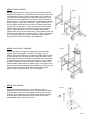
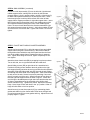
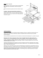
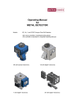
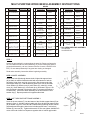
MULTI-PURPOSE WORK BENCH ASSEMBLY INSTRUCTIONS
#92558
DESCRIPTION
ORDER PART # QTY
DESCRIPTION
ORDER PART # QTY
DESCRIPTION
ORDER PART # QTY
A M10 X 55MM BOLT
3
N
LARGE WHEEL
WB0002
2
AA
DRAIN PLUG
WB0015
1
B
M6 X 50MM BOLT
6
O
WHEEL COVER
WB0003
4
BB
DOWEL RODS
WB0016
3
C
M6 X 16MM BOLT
16
P
AXLE SLEEVE
WB0004
3
CC
REAR FAUCET
PANEL
WB0017
1
D
M6 NUT
12
Q
RIGHT SUPPORT
FRAME
WB0005
1
DD
FOLDING
COUNTER
WB0018
1
E
6MM WASHER
6
R
LEFT SUPPORT
FRAME
WB0006
1
EE FOLDING COUNTER
WB0019
1
F
10MM WASHER
5
S
CUSHION
HANDLE GRIP
WB0007
1
FF
DRAWER
WB0020
1
G
12MM WASHER
4
T
CASTERS
WB0008
2
GG
BOTTOM TRAY
WB0021
2
H
10MM END CLIP
2
U
FRONT SUPPORT
BAR
WB0009
1
HH
“S” HOOKS
WB0022
6
I
12MM END CLIP
4
V
REAR SUPPORT
BAR
WB0010
1
II
FAUCET
WB0023
1
J
10MM PVC COVER
2
W MIDDLE SUPPORT
WB0011
1
JJ
FOLDING COUNTER
HINGE
WB0024
2
K 12MM PVC COVER
2
X
FRONT PANEL
WB0012
1
L M6 PVC NUT COVER
4
Y
COILED SHELF
WB0013
1
TOOLS REQUIRED FOR ASSEMBLY
Hex Wrench
Hex Bolt Driver
1
Z
SINK TOP BASIN
WB0014
1
M
WHEEL AXLE
WB0001
FRAME
AXLE FOR
STEP 1
identify all parts packed in carton against the parts list. Remove all protective materials. Place parts
on a non-arasive surface to avoid scratching. If you are missing any parts or are unsure how to
proceed with assembly, call our Customer Service Center at 1-800-416-3511 (Mon - Fri 9a-5p
EST). Do not attempt assembly if any parts are missing or damaged.
Read entire assembly instructions before beginning assembly.
Figure 1
STEP 2 WHEEL ASSEMBLY
Insert wheel axle (M) through bottom shaft of right side support frame
(Q).so that it is centered inside the shaft with equal amount of axle on
each side. Snap 12mm end clip (I) on notch in axle closest to the right
side support frame (Q). Add the following parts to the axle in this order:
12mm washer (G), wheel cover (O), axle sleeve (P), wheel (N), wheel
cover (O), 12mm washer (Q), 12mm end clip (I) as shown in figure 1. Be
sure the wheel is inserted over the axle sleeve in a manner that allows it
to rotate freely. Secure the wheel assembly on the axle with the 12mm
washer clip (I). Repeat procedure for opposite side wheel.
STEP 3 LEFT SIDE SUPPORT FRAME ASSEMBLY
Screw in the two casters (T) into the bottom of the left side support frame (R) as
shown in figure 2. Add the cushion handle grip (S) to the left side support frame
(R) as shown in figure 2. Insert two M6 x 50mm bolts (B) through end of cushion
grip handle and through the holes in the left side support frame. Add a 6mm
washer (E), 6mm nut (D). Tighten with wrench. Do not over tighten. Add M6 PVC
cover to the end of each nut. Repeat on opposite side of cushion grip handle.
Figure 2
PAGE 1
STEP 4 FRAME ASSEMBLY
Figure 3
Connect right side support frame (Q) and left side support frame (R)
using the rear support bar (V). Be sure that the hole in the center of the
rear support bar is facing up. Add a 10mm washer (F) to a M10 x 55
mm bolt (A) and insert through the left side frame support(r) into the
fixed nuts in the rear support bar (V) as shown in figure 3. Repeat for
opposite side. (Q). Attach front support bar to middle support frame as
shown in figure 3 using a M6 x 16mm bolt. Tighten with wrench. Do
not over tighten. With bottom of rear portion of middle support frame
resting on the rear support bar, attach front support bar to right side
support frame (with wheels) using M6x 16mm bolt (C) as shown in
figure 3. Tighten with wrench. Do not over tighten. Attach middle
support frame (W) to the rear support bar (V). Align middle support bar
with hole in rear support bar as shown in figure 4. Add a 10mm washer
(F) to an M10 x 55mm bolt (A). Insert bolt through middle support
frame and into the fixed nut inside the rear support bar.
STEP 5 COILED SHELF ASSEMBLY
Figure 4
Attach coiled shelf (Y) to right side support frame (Q) and middle
support frame (W) using M6 x 16 bolts (C) as shown in figure 4.
Position coiled shelf between the right side and middle support frames
so that coiled portion of the panel is acing towards the bottom. Insert
bolts through the holes from behind the coiled shelf and into the fixed
nuts inside the right side and middle support frames. Use hex wrench
to tighten completely. Do not over tighten. Attach front panel to left
side and middle support panels as shown if figure 4 using M6 x 16mm
bolts (C). Insert bolts through holes from behind the front panel into the
fixed nuts in the front portion of the left side and middle support
frames. Tighten using hex wrench. Do not over tighten.
STEP 6 SINK ASSEMBLY
Figure 5
Install sink drain/stopper assembly (AA) as shown in figure 5.
Separate the three pieces and insert the center gasket into the whole
in the sink basin. Insert the funnel-shaped portion into the sink drain
as shown. From underneath the sink basin, attach the bottom portion
of the sink drain/stopper assembly onto the bottom portion of the
funnel shaped piece to hold firmly in place.
PAGE 2
STEP 6 SINK ASSEMBLY (continued)
Position the sink top assembly (Z) over the left side, right side and
middle support frames, making sure the holes for the bolts are
properly aligned. Once in proper position, use M6 x 16mm bolts (C)
to attach sink top/basin assembly to the left support frame. Insert
bolts through holes in sink top into the fixed nuts in the left side
support frame. Repeat procedure for right side support frame. Insert
M6 x 50mm bolts (B) through the holes in the middle portion of the
sink top/basin assembly through the holes in the middle support
frame. Be sure to insert the bolts in the direction towards the right
side support frame as shown in figure 6. Add a 6mm washer (E) and
an m6 nut to the end of each bolt. Tighten with wrench. Do not over
tighten.
Figure 6
STEP 7 FAUCET AND FOLDING COUNTER ASSEMBLY
Attach rear faucet panel (CC) to left side support frame and middle
support frame using M6 x 16mm bolts (C). Insert bolts outwards
through holes from behind the rear faucet panel and into the fixed
nuts in the middle support frame. Repeat procedure for opposite
side. Tighten bolts using hex wrench. Tighten completely. Do not
over tighten.
Attach the three dowels rods (BB) by snapping into place as shown.
Two on left side, one on right side beneath the coiled shelf.
Figure 7
Attach folding counter (DD) to right side of the assembled unit.
Position the folding counter between the axle guides on the right
side support frame (just below where it meets with the sink top/basin
assembly). Slide the folding shelf axle (EE) through the axle guides
and through the hollow shaft of the folding shelf. Add 10mm washer
to each end of the axle. Secure into place by attaching 10mm end
clips (H) to each end of the axle. Attach lower part of front hinge to
the front right side support frame as shown in figure7. Attach one
end of hinge to threaded post on right side frame and the other end
of hinge to threaded post on the underside of the folding shelf.
Secure with M6 nut (D). Tighten with wrench. Repeat for remaining
hinge. Note: hinge will lock with shelf in the “up” position. Collar on
hinge will slide down to lock into position.
Attach faucet (II) to rear faucet panel (CC) by unscrewing plastic
gasket and sealer ring from faucet head. Place faucet through hole
in rear faucet panel and re-screw gasket and ring. Adjust faucet until
properly aligned. Tighten.
PAGE 3
STEP 8 FINAL TOUCHES
Drawer assembly. Tilt the front end of drawer up and slide into
track. Make sure track and drawer runners are properly
aligned.
Figure 8
Slide the two bottom trays (GG) into frame as shown in figure
8.
At this time, make sure all nuts and bolts are tightened
completely using wrench and hex key wrench. Do not over
tighten. Add 12mm PVC cover (K) to each end of wheel axle
and 10mm PVC cover (J) to each end of the folding shelf axle
as shown in figure 8.
LIMITED WARRANTY
This warranty is extended to the original purchaser and applies to defects in materials and workmanship of our
Outdoor Living patio furniture, provided your furniture is maintained with care and used only for personal,
residential purpose.
Frames and Welds are warranted to be free from defects in materials and workmanship for a period of five years.
Exclusions: Items used for commercial, contract or other non-residential purposes, display models, items
purchased “as is,” or items damaged due to acts of nature, vandalism, misuse or improper assembly are not
covered. Discoloration or fading of the finish or fabric (if applicable) as a result of exposure to the elements,
chemicals or spills are not covered. Table top breakage, corrosion or rusting of hardware, loss of use or other
incidental damages are not covered.
If within the stated warranty period a product is found to be defective in material or workmanship, the purchaser
must contact the manufacturer’s customer service center at 1-800-416-3511. The manufacturer will, at its option,
repair or replace the defective parts.
Warranty is to the original purchaser only and is non-transferrable. Any replacement of warranted items will be in
the original style and color. If original style and color is not available or has been discontinued, an item of similar
style and color will be substituted. As some states do not allow exclusions or limitations on an implied warranty,
the above exclusions and limitations may not apply. This warranty gives you specific rights and you may also
have other rights which vary from state to state.
PAGE 4