1
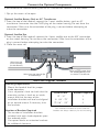
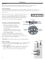
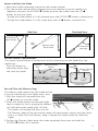
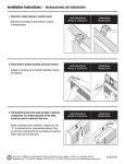
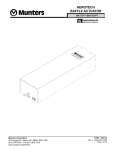
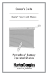
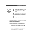
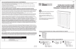
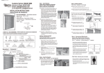
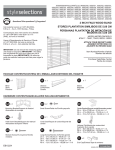
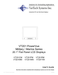
PowerVue
Installation Instructions
and Owners Manual
Table of Contents
Introduction . . . . . . . . . . . . . . . . . . . . . . . . . . . . . . . . . . . . . . . . . . . . . . . . . . . . . . . . . . . . . . .2
Installation Instructions . . . . . . . . . . . . . . . . . . . . . . . . . . . . . . . . . . . . . . . . . . . . . . . . . . . . . .2
Materials Included . . . . . . . . . . . . . . . . . . . . . . . . . . . . . . . . . . . . . . . . . . . . . . . . . . . . . . . . . .2
Tools And Supplies Needed . . . . . . . . . . . . . . . . . . . . . . . . . . . . . . . . . . . . . . . . . . . . . . . . .3
Install The Battery Wand . . . . . . . . . . . . . . . . . . . . . . . . . . . . . . . . . . . . . . . . . . . . . . . . . . . .3
Connect The Optional Components . . . . . . . . . . . . . . . . . . . . . . . . . . . . . . . . . . . . . . . . . .4
Mount The Installation Brackets . . . . . . . . . . . . . . . . . . . . . . . . . . . . . . . . . . . . . . . . . . . . . . .5
Install The Shade . . . . . . . . . . . . . . . . . . . . . . . . . . . . . . . . . . . . . . . . . . . . . . . . . . . . . . . . . . .7
Install The Optional Components . . . . . . . . . . . . . . . . . . . . . . . . . . . . . . . . . . . . . . . . . . . . .7
Remove The Shade . . . . . . . . . . . . . . . . . . . . . . . . . . . . . . . . . . . . . . . . . . . . . . . . . . . . . . . . .9
Operation . . . . . . . . . . . . . . . . . . . . . . . . . . . . . . . . . . . . . . . . . . . . . . . . . . . . . . . . . . . . . . .10
Replacing Batteries . . . . . . . . . . . . . . . . . . . . . . . . . . . . . . . . . . . . . . . . . . . . . . . . . . . . . . . .12
Troubleshooting . . . . . . . . . . . . . . . . . . . . . . . . . . . . . . . . . . . . . . . . . . . . . . . . . . . . . . . . . . .13
Care And Cleaning . . . . . . . . . . . . . . . . . . . . . . . . . . . . . . . . . . . . . . . . . . . . . . . . . . . . . . . .15
Materials Included
Extension Brackets
(Optional)
Spacer Blocks
(Optional)
Installation Brackets
CAUTION: TO AVOID DAMAGE, DO NOT DROP THE BATTERY WAND.
Use 8 AA alkaline batteries as shown below.
TO REPLACE BATTERIES,
REMOVE CAP FROM THIS END.
INSTALL THIS END
TOWARDS SPRING.
Headrail with Raise
Covered Rail
Install battery wand with label facing outward. For assistance call 1-800-327-8953.
B ATTE R Y WAND.
CAUTION: TO AVOID DAMAGE , DO NOT DR OP THE
Us e 8 AA a lka line ba tterie s a s s hown below.
INS TALL THIS E ND
TOWAR DS S PR ING.
Satellite
Battery Pack
(Optional)
Headrail
TO REPLACE BA TTERIES,
REMOVE CAP FROM THIS END.
ta nce ca ll 1-800-327-8953.
Ins ta ll ba ttery wa nd with la bel fa cing outwa rd. F or a s s is
Infrared
Eye
Manual
Control
Button
Satellite Eye
(Optional)
End Cap
Honeycomb
Fabric
Bottom
Rail
2
AC Transformer
(Optional)
Remote Control
Bottom Rail
End Cap
Tools and Supplies Needed
-
Carpenter’s level
Measuring tape
Power drill, 1/4" hex driver, and drill bits
Screwdrivers (flat blade and Phillips)
Wood screws or other fasteners, such as
expansion bolts, toggle bolts, or anchors
(not included)
Mounting Surface
Wood
Fasteners
No. 6 Hex Head Screws
(Not Provided)
Drywall Plaster
Wall Anchors, Expansion Bolts
(Not Provided)
Metal
Sheets Metal Screws
(Not Provided)
Install the Battery Wand
(CAUTION: Use only alkaline batteries. Do not use rechargeable batteries.)
Removable End Cap
1. Install the batteries according to the instructions
on the battery wand label.
AA Battery Wands Used For Shades More Than 26" Wide
Removable End Cap
2. Install the wand into the headrail with the label
facing you.
CAUTION: TO AVOID DAMAGE,
DO NOT DROP THE BATTERY WAND.
Use 8 AAA alkaline batteries as shown below.
TO REPLACE BATTERIES,
REMOVE CAP FROM THIS END.
INSTALL THIS END
TOWARDS SPRING.
Install battery wand with label facing outward.
For assistance call 1-800-327-8953.
AAA Battery Wands Used For Shades Less Than 26" Wide
AA Battery Wands
- For AA battery wands, place the end of the wand
with the non-removable end cap into the spring
clip.The arrow on the label of the battery wand
should point toward the spring clip.
Pivot Release Clip
Spring Clip
INS TALL
TOWAR DSTHIS E ND
S P R ING.
s ha ding
. 2) Tilt
we rR
is e ®:
DOWN?
va ne s
1)
comple
ully lowe
button
button
te ly
- Hold
to clos
5 s e conds ope n. 3)
e a nd
P re s s
. 4) P
comple
re s s UP
te ly ra
is e s ha
?
ding .
®
B ATTE R
CAUTION:
Y OR
IE NTATITO AVOID
ON S HODAMAGE
WN B E L, DO NOT
Us e 8 AA
W. US DR
a lka line O
E 8OPAA
THE
ba tteries
B ABATTE
TTE RRIEY SWAND.
a s s hown
below.
. US E AL
KAL INE
wa nd with
Ins ta ll ba
© 1998 Hunter
ttery
Doug la s Inc.
la bel fa cing
outwa rd.
F or a s s is
ta nce ca ll
1-800-327-89
53.
B ATTE R
IE S ONL
Y.
TO R E P LACE
BATTE
R E MOVE
CAP F R OM R IE S ,
THIS E ND.
Infrared Eye on the Right Side of the shade
Spring Clip
Pivot Release Clip
r
re s e t a fte
mus t be
de.
lowe r s ha
. 1) F ully
e conds .
ba tte rie s
Hold 5 s
cha ng ing
button s ha de.
DOWN?
te ly ra is e
2) P re s s
to compl
UP ? button
3) P re s s
lowe r
: 1) F ully
er
3) P re s s
S ilhoue tte
te ly ope n.
To re s e t
UP ?
ne s comple
4) P re s s
2) Tilt va
e conds .
s ha ding .
Hold 5 s
ha ding .
button ly ra is e s
DOWN?
comple te
clos e a nd
button to
© 1998 H
P owe
e
®
unte r Douglas
Y WAND.
B ATTE R
DR OP THEbelow.
, DO NOT
hown
DAMAGE ba tteries a s s
TO AVOID
a lka line
CAUTION:
Us e 8 AA
ca ll 1- . 2981 09 7000
s s is ta nce
nding
rd. F or a fore ign pa tents pe
fa cing outwaInc. U.S. a nd
Douglas
with la bel
of Hunter
dem a rks
ttery wa nd
Ins ta ll baIn c. ® Registered tra
re v. 2 /98
20M
S,
ATTE R IE
LACE B
E ND.
TO R E P
OM THIS
CAP F R
R E MOVE
Infrared Eye on the Left Side of the Shade
AAA Battery Wands
Spring Clip
3. Push the other end of the wand into the pivot
release clip and snap closed.
THIS E ND
INS TALLDS S P R ING.
TOWAR
- For AAA battery wands, place the end of the
wand with the removable end cap into the spring
clip. The arrow on the label of the battery wand
should point toward the spring clip.
Pivot Release Clip
TO R E
P LACE
US E 8
BATTE
CAP F R
AAA BATTE
R IE S , R
OM THIS
R IE S
E MOVE
THIS E
BATTE . US E ALKAL
ND TOWA E ND. R E INS
INE BATTE
R Y OR
TALL
R DS S
IE NTATI
R IE S ONLY.
P R ING.
ON:
R E INS
TO
TALL B
ATTE R
CLOS E
Y WAND
F OR AS
R AIL
S IS TANCE WITH LAB E L
F ACING
CALL
OUTW COVE R :
AR D.
P US H
UP ON
LATCH
AR M
Infrared Eye on the Right Side of the Shade
4. Make sure the wand is securely seated in both
the spring clip and pivot release clip.
Pivot Release Clip
Spring Clip
D.
OUTWAR
R E M OV E
TE R I E S ,
E L F ACING
ACE B AT
S TAL L
WITH LAB
TO R E P L THIS E ND. R E IN
R Y WAND
M
G . R E INS TALL B ATTE TANCE CALL
CAP F R O OWAR DS S P R IN
S IS
F OR AS
DT
THIS E N
B ATTE
US E 8 AAA
R
E B ATTE
E ALKALIN
R IE S . US
IE S ONLY.
TO
CL OS E
R AIL
COV E R :
P US H
UP ON
LA TCH
AR M
Po
5. Close the cover of the headrail. Allow 30 seconds
for the system to power up.
Infrared Eye on the Left Side of the Shade
3
Connect the Optional Components
If you ordered the satellite battery pack or AC transformer, connect it to the motor.
1. Flip up the cover rail to open.
Optional Satellite Battery Pack or AC Transformer
2. From the top of the headrail, connect the 2-port satellite battery pack or AC
transformer connector into the PWR plug on the motor housing. Do not force the
connection. Make sure the orientation of the plug is correct before attempting to
make the connection.
Optional Satellite Eye
3. From the top of the headrail, connect the 4-port satellite eye to the SAT connection
on the motor housing. Do not force the connection. Make sure the orientation of the
plug is correct before attempting to make the connection.
4. Close the cover rail.
Wire from the
Limit Assembly
(Do Not Remove)
Wire carrying power from
the Satellite Battery Pack
or the AC Transformer
Wire from the Internal Eye
or Satellite Eye
Tools and Supplies Needed
Mounting Requirements
- Mount the headrail level for proper
shade operation.
- Use a carpenter’s level to check that the
mounting surface is level on an inside
mount and that the tops of the
installation brackets are level and aligned
on an outside mount. If necessary, shim
the brackets.
Number of Brackets Required
- The number of installation brackets
included with each shade depends upon
the ordered width.
- Use spacer blocks or extension brackets
for additional clearance.
4
Shade Width*
Brackets Required
19” - 31”
2
31 1/8” - 79”
3
79 1/8” - 120”
4
*End mount maximum width Is 65".
Two installation brackets and two extension
brackets are always necessary for end mounting.
Mounting the Installation Brackets
Bracket Spacing
Bracket spacing is the same for inside, outside, or ceiling mounted shades. End
mounting is explained on page 6.
1. Space the two end brackets so that their outside edges are at least 5/8" in from the
ends of the headrail.
Minimum of
5/8”
Space Evenly
Minimum of
5/8”
Space Evenly
Headrail
2. Space additional brackets, if used, evenly between the two end brackets.
3. Adjust the bracket positions to accommodate any obstructions to the bottomrail, such
as window cranks or handles.
4. Measure and mark all bracket locations.
Inside Mount Applications
The minimum mounting depth is 5/8”.
Minimum
Depth
Fully
Recessed
5/8”
5/8”
5/8”
See
Depth
Chart
Bracket Placement
The depth required to fully recess a shade depends on the pleat size.
Depth Chart: Inside Mount Bracket Placement
Pleat Size
3/8”
3/4”
Honeycomb Double Cell
Minimum
5/8”
5/8”
5/8”
Fully Recessed
2”
2 1/2”
2 1/2”
Note: For optimal operation of the infrared eye, the shade should not be recessed past
the front of the window opening.
1. Place both end brackets so that their outside edges abut the marks on the mounting
surface.
2. Check that each bracket is level and aligned.
3. Attach using two screws.
5
Outside Mount Applications
The minimum mounting depth is 3/4”.
Bracket Placement
1. Center the shade over the window opening and mark
the ends of the headrail.
2. Measure a minimum of 5/8" in from the marks on the
wall and mark the bracket locations.
3. Align both end brackets so that their outside edges
abut the bracket marks on the mounting surface.
4. Adjust the bracket position to accommodate any
obstructions to the bottom rail, such as window
cranks or handles.
5. Check that each bracket is level and aligned.
6. Attach using two screws.
Spacer Blocks (Optional)
Each spacer block projects brackets 1/2" away from the
mounting surface.
Note: Longer screws (not provided) are required to
secure the spacer blocks and the installation
brackets to the mounting surface.
1. Mount spacer blocks with the solid side facing the
mounting surface. Use a maximum of three spacer
blocks per bracket.
2. Secure with two screws.
Extension Brackets (Optional)
Extension brackets project the installation brackets up to
3" away from the mounting surface.
5/8”
Minimum
Mark
on Wall
3/4”
Minimum
Spacer Blocks
/"
12
/"
12
/"
12
Nuts
Extension Bracket
1. Mount the extension brackets on a surface at least
3/4" high.
2. Check that each bracket is level and aligned.
3. Attach using two screws.
4. Attach the installation brackets to the extension brackets
using the machine screws and nuts provided.
End Mount Applications
End mount the headrail when conventional mounting
techniques will not work, for example, in an arched
window opening.The maximum width of an end-mounted
shade is 65".
1. Mount the extension brackets on a surface at least
1 1/2" wide.
2. Attach the installation brackets to the extension brackets
using the machine screws and nuts provided.
6
Installation
Bracket
Nuts
Extension Bracket
Installation
Bracket
1 1/2”
Minimum
Install the Shade
(CAUTION: be sure the wires coming from the satellite eye, satellite battery pack, or AC transformer do not
become pinched by the brackets or headrail during installation.)
Note: If using a satellite eye, remove the rubber bands holding the satellite eye to the
headrail. If the satellite eye is not connected to the shade, plug the 4-wire satellite
eye connector into the 4-wire slot marked “SAT” on the motor housing.
1.Tip the headrail forward and fit the back bottom edge into the lower lip of each bracket.
2. Rotate the headrail up until it snaps into the locking tab on the back of each bracket.
Locking Tab of Bracket
Headrail
Cover
Lower Lip
of Headrail
Headrail Properly Installed
Install the Optional Components
Once the optional components (satellite battery pack, satellite eye, and AC transformer)
are connected and the shade installed, install the components.
Satellite Battery Pack
Determine where to mount the satellite battery pack.
1. Mount the satellite battery pack in a location where it will not
interfere with the shade’s operation.
2. On Outside Mounts - route the wire so it exits from the
top of the shade.
On Inside Mounts - route the wire so it runs along the control
side end cap to the front of the shade
Outside
Mount
Inside Mount
Mount the satellite battery pack
1. Remove the cover of the battery pack by pressing on the
circular latch and lifting the cover off.
2. Use the holes in the rear of the pack as a template to mark
the screw locations on the mounting surface.
3. Attach using two screws
Load batteries into the satellite battery pack
1. Install eight AA alkaline batteries, according to the
instructions on the battery pack.
2. Replace the cover, snapping it securely closed.
7
Satellite Eye
(CAUTION: Handle the satellite eye carefully to avoid damaging the infrared eye.
Do NOT touch or push on the infrared eye.
Determine where to mount the satellite eye
1. Choose a location for the satellite eye where the
signal from the remote is not obstructed. Do not
mount the satellite eye in direct sunlight or bright,
focused light from halogen or fluorescent light
fixtures, track lighting, spotlights, or neon lights.
2. Check that the wire is not caught or pinched
in the brackets or headrail.
3. With inside mounts, route the wire behind the
headrail and along the side of the end cap to the
front of the shade.
Outside Mount
Inside Mount
Mount the satellite eye
1. Flip the satellite eye down and place the hinged
flange against the wall. Attach the flange to the wall
with a single screw.
2. Swivel the satellite eye upward to the correct angle
for receiving the signal from the remote control.
Wall
AC Transformer
The AC transformer plugs into a standard 110V outlet.
1. Route the wire to a location where it will not interfere with the shade.
2. On outside mounts, the wire exits from the top of the shade.
On inside mounts, the wire runs along the control side end cap to the
front of the shade.
3. After the AC transformer has been attached to the 2-pin power
connector on the headrail and the headrail has been installed, plug
the AC transformer into a 110V outlet.
Outside Mount
8
Inside Mount
P/N # 298119800
AC-DC Adaptor
MODEL: MKD-48121000
INPUT: 120V AC 60 Hz 0.3A
OUTPUT: 12V DC 100 mA
Listed
Install the Remote Control
1. Remove the back center panel of the remote control by
pushing down on the latch and pulling it out. Remove
both AAA batteries inside.
2. Replace the batteries with two new AAA alkaline
batteries as shown inside the remote control.
3. Replace the back cover panel.
See the Operating Instructions in the next section for the
procedures for resetting and operating the shade.
Remove the Shade
There are two ways to remove the headrail from
the mounting bracket.
Cover Rail
Bracket Locking Tab
- Access the locking tab through the front of the headrail.
1. Lift the cover rail.
2. Push in on the locking tab and rotate the headrail
out of the bracket.
- Access the locking tab from behind the headrail.
1. Insert a long, flat blade screwdriver between the back
of the installation bracket and the headrail.
2. Push up on the locking tab and rotate the headrail
out of the bracket.
Headrail
To release, lift the Cover Rail
and push in on the Locking Tab
Bracket
Locking Tab
Headrail
9
Operation
First Use
Ascent Honeycomb Shades must be reset before the first use (see below).
See the next section for resetting and testing the shade operation.
Channel Selection
Ascent Honeycomb shades operate on specially designated channels, Channel 1 or
Channel 2. To operate the shade, the remote control must be set on the same channel
as the shade.
Shades are set to Channel 1 unless specified for Channel 2 at
the time of ordering. When specified, for example with
adjacent or stacked shades, shades are set to Channel 2.
A decal attached to the motor housing, visible under
the cover rail, indicates Channel 2 operation.
Shade Motor
To switch a shade’s operating channel:
1. Remove the shade from the mounting
brackets and open the cover rail.
- The channel selector is located on
the motor board next to the limit
assembly plug.
Position for
- The right switch controls the channel
Standard
Ascent
operation and the left switch controls
the shade operation.
2. Using a small, flat blade screwdriver flip the
right channel selector switch toward the front of
the shade for Channel 1 operation or toward the back
of the shade for Channel 2 operation.
Channel 1
Position
(Standard)
CAUTION: Leave the left side switch in the front position.
Channel
Selector
Reset the Shade
1. Select the shade’s operating channel on the remote control.
2. Press and release the DOWN ▼ button to lower the
shade completely.
3. With the shade completely lowered, press and hold the
DOWN ▼ button for 5 seconds.This will clear the
memory and the shade can be operated normally.
Up
Down
10
Indicator
Light
Lower and Raise the Shade
1. Select the shade’s operating channel on the remote control.
2. Aim the remote control at the infrared eye on the headrail or on the satellite eye
(optional) and press the DOWN ▼ button to lower the shade. Press the UP ▲
button to raise the shade.
- To stop the shade before it is fully lowered, press the DOWN ▼ button a second time.
- To stop the shade before it is fully raised, press the UP ▲ button a second time.
Side View
Overhead View
Shade
55º Maximum
upward angle
Aim
High
Operate within
30º of shade
12
45º Maximum
side angle
®
Shade
Use the Manual Control Button
The manual control button is located next to the infrared eye on the headrail or the
satellite eye.
Infrared
Manual Control
Infrared
Eye
- Press the button to
Button
Eye
alternately lower, stop,
Manual Control
Button
Headrail
and raise the shade.
Satellite Eye
Set and Clear the Memory Stop
The Memory Stop feature sets the shade so that
it can be raised to the same height every time.
1. With the shade fully lowered, press the
UP ▲ button to raise the shade.
2. When the shade reaches the desired height,
stop its motion by firmly grasping the bottom
rail with both hands, keeping the rail level.
- The motor will hesitate and then shut off.
- The Memory Stop will be set, and the shade will automatically stop at that point each
time it is raised. Until the Memory Stop is cleared, the shade cannot be raised any
higher.
3.To clear the Memory Stop, lower the shade completely, then press and hold the
DOWN ▼ button for 5 seconds.
11
Replacing the Batteries
(CAUTION: Use only alkaline batteries. Do not use rechargeable batteries.)
Removable End Cap
AA Battery Wands Used For Shades More Than 26" Wide
Removable End Cap
CAUTION: TO AVOID DAMAGE,
DO NOT DROP THE BATTERY WAND.
Use 8 AAA alkaline batteries as shown below.
TO REPLACE BATTERIES,
REMOVE CAP FROM THIS END.
INSTALL THIS END
TOWARDS SPRING.
2. Install the wand into the headrail with the
label facing you.
Install battery wand with label facing outward.
For assistance call 1-800-327-8953.
AAA Battery Wands Used For Shades Less Than 26" Wide
AA Battery Wands
Pivot Release Clip
Spring Clip
s ha ding
. 2) Tilt
we rR
is e ®:
DOWN?
va ne s
1)
comple
ully lowe
button
button
te ly
- Hold
to clos
5 s e conds ope n. 3)
e a nd
P re s s
. 4) P
comple
re s s UP
te ly ra
is e s ha
?
ding .
®
B ATTE R
CAUTION:
Y OR
IE NTATITO AVOID
ON S HODAMAGE
WN B E L, DO NOT
Us e 8 AA
W. US DR
a lka line O
E 8OPAA
THE
ba tteries
B ABATTE
TTE RRIEY SWAND.
a s s hown
below.
. US E AL
KAL INE
wa nd with
Ins ta ll ba
© 1998 Hunter
ttery
Doug la s Inc.
la bel fa cing
F or a s s is
ta nce ca ll
1-800-327-89
53.
B ATTE R
IE S ONL
Y.
TO R E P LACE
BATTE
R E MOVE
CAP F R OM R IE S ,
THIS E ND.
Infrared Eye on the Right Side of the shade
Spring Clip
Pivot Release Clip
© 1998 H
P owe
e
®
unte r Douglas
Y WAND.
B ATTE R
DR OP THEbelow.
, DO NOT
hown
DAMAGE ba tteries a s s
TO AVOID
a lka line
CAUTION:
Us e 8 AA
ca ll 1- . 2981 09 7000
s s is ta nce
nding
rd. F or a fore ign pa tents pe
fa cing outwaInc. U.S. a nd
Douglas
with la bel
of Hunter
dem a rks
ttery wa nd
Ins ta ll baIn c. ® Registered tra
re v. 2 /98
20M
S,
ATTE R IE
LACE B
E ND.
TO R E P
OM THIS
CAP F R
R E MOVE
- For AAA battery wands, place the end of the wand
with the removable end cap into the spring clip. The
arrow on the label of the battery wand should point
toward the spring clip.
outwa rd.
r
re s e t a fte
mus t be
de.
lowe r s ha
. 1) F ully
e conds .
ba tte rie s
Hold 5 s
cha ng ing
button s ha de.
DOWN?
te ly ra is e
2) P re s s
to compl
UP ? button
3) P re s s
lowe r
: 1) F ully
er
3) P re s s
S ilhoue tte
te ly ope n.
To re s e t
UP ?
ne s comple
4) P re s s
2) Tilt va
e conds .
s ha ding .
Hold 5 s
ha ding .
button ly ra is e s
DOWN?
comple te
clos e a nd
button to
- For AA battery wands, place the end of the wand
with the non-removable end cap into the spring clip.
The arrow on the label of the battery wand should
point toward the spring clip.
INS TALL
TOWAR DSTHIS E ND
S P R ING.
THIS E ND
INS TALLDS S P R ING.
TOWAR
Replace the batteries in the wand
1. Install the batteries according to the instructions on
the battery wand label.
Infrared Eye on the Left Side of the Shade
AAA Battery Wands
Spring Clip
Pivot Release Clip
TO R E
P LACE
US E 8
BATTE
CAP F R
AAA BATTE
R IE S , R
OM THIS
R IE S
E MOVE
THIS E
BATTE . US E ALKAL
ND TOWA E ND. R E INS
INE BATTE
R Y OR
TALL
R DS S
IE NTATI
R IE S ONLY.
P R ING.
ON:
R E INS
3. Push the other end of the wand into the pivot
release clip and snap closed.
TO
TALL B
ATTE R
CLOS E
Y WAND
F OR AS
R AIL
S IS TANCE WITH LAB E L
F ACING
CALL
OUTW COVE R :
AR D.
P US H
UP ON
LATCH
AR M
Infrared Eye on the Right Side of the Shade
Pivot Release Clip
R
E B ATTE
E ALKALIN
R IE S . US
IE S ONLY.
TO
CL OS E
R AIL
COV E R :
P US H
UP ON
LA TCH
AR M
Po
Infrared Eye on the Left Side of the Shade
Replace the Batteries in the Satellite Battery Pack
Load batteries into the satellite battery pack
1. Install eight AA alkaline batteries, according to the
instructions on the battery pack.
2. Replace the cover, snapping it securely closed.
Replace the Remote Control Batteries
1. Remove the back center panel of the remote control by pushing down
on the latch and pulling it out. Remove both AAA batteries inside.
2. Replace the batteries with two
new AAA alkaline batteries as
shown inside the remote control.
3. Replace the back cover panel.
12
B ATTE
US E 8 AAA
5. Close the cover of the headrail. Allow 30 seconds
for the system to power up.
Spring Clip
D.
OUTWAR
R E M OV E
TE R I E S ,
E L F ACING
ACE B AT
S TAL L
WITH LAB
TO R E P L THIS E ND. R E IN
R Y WAND
M
G . R E INS TALL B ATTE TANCE CALL
CAP F R O OWAR DS S P R IN
S IS
F OR AS
DT
THIS E N
4. Make sure the wand is securely seated in both the
spring clip and pivot release clip.
Troubleshooting
Problem
The shade does not operate using either
the remote control or the manual control
button.
Solution
- Check that the battery wand is oriented
correctly in the headrail.
- Check that the battery wand is completely
inserted in the clips and fits snugly in the
headrail.
- Check that the batteries in the wand are
installed correctly and fresh. See Replace
The Batteries In The Battery Wand, page 12.
- Check that the AC transformer, if used, is
securely plugged into the wall outlet and
that the outlet has power.To check that
the outlet has power, plug in a lamp or
device that is known to work.
- Check that the AC transformer, if used, is
securely connected to the motor. See
Install The AC Transformer, page 8.
The shade operates using the manual
control button, but does not operate using
the remote control.
- Check that the correct channel is
selected on the remote.
See Channel Selection, page 10.
- If the red light on the remote control
does not light up when the UP ▲ /
DOWN ▼ buttons are pressed, replace
the batteries in the remote control.
See Replace The Remote Control Batteries,
page 12.
- Check that you are pointing the remote
control directly at the infrared eye. See
Lower And Raise The Shade, page 11.Try
moving closer to the eye. Maximum
operating distance from the remote
control is 30 feet.
- Check that there are no obstructions
impeding the signal from the remote
control to the infrared eye.
- Check that there is no direct sunlight or
bright, focused light from halogen or
fluorescent light fixtures, track lighting,
spotlights, or neon lights that could be
interfering with the signal.
13
Troubleshooting
Problem
The shade does not lower completely.
Solution
- Check for obstructions in the shade’s path.
The shade does not raise completely.
- The Memory Stop may be activated. See
Set And Clear The Memory Stop, page 11.
- Check the batteries and replace if
necessary.
The shade does not hang correctly.
- Check that the mounting brackets are
level.
Adjacent shades do not stack evenly.
- If one shade is stacking tighter than
another, it has probably been reset. Simply
lower and raise the shade to loosen the
stack.The shade stack on both shades
should be within 5/16" of each other.
- For more exact stacking, use the Memory
Stop feature. See Set And Clear The
Memory Stop, page 11.
The shade operation is slowing.
- Remove the battery wand and replace the
batteries. See Replace The Batteries In The
Battery Wand, page 12.
14
Care and Cleaning
Ascent Honeycomb shades are as durable as they are beautiful. With proper installation
and care, they will provide many years of beauty and performance.The honeycomb fabric
is anti-static and dust-resistant. Light dusting is all that is generally needed to keep your
shade looking like new.
CAUTION: Never submerge the headrail in any solution.
Routine Cleaning
- Use a feather duster for regular, light dusting.
- For more thorough dust removal, light vacuuming using a brush attachment or
hand-held vacuum with low suction is recommended.
- The headrail and remote control may be wiped clean with a damp sponge
and mild detergent.
Spot-Cleaning
To reduce the potential for permanent staining, spots should be cleaned as soon
as possible.
- Use a soft cloth or sponge moistened with lukewarm water.
- Add mild detergent if necessary.
- Gently blot the spot. Avoid rubbing the fabric since any abrasive action may cause it to
distort.
- Let the shade dry in the completely lowered position.
Deep Cleaning
- Water immersion cleaning methods are not recommended for Ascent Honeycomb
shades. Do not dry clean or use injection/extraction or ultrasonic cleaning methods
with your shades.
15
Ascent Honeycomb Shades Installation & Guide
T2436
December 2005