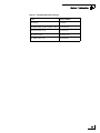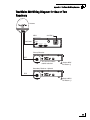
1
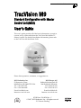
User’s Guide
TracVision M9
TracVision M9
Standard Configuration
TracVision M9
Addendum
TracVision M9 Standard Configuration with
Master Control Unit User’s Guide Addendum
®
(ECO #8127)
The following change applies to Revision C of the TracVision M9
Standard Configuration with Master Control Unit User’s Guide
(KVH Part #54-0420).
Programming User-defined Satellites
Step 5 on page 56 shows the incorrect @SATCONFIG command; the
satellite table field is omitted.
The correct @SATCONFIG command and field values are shown
below.
5. Type the following @SATCONFIG command then
press Enter:
@SATCONFIG,X,D,E,F,G,H,I,J,K
54-0420 Addendum to Rev. C
Field
Description
X
User-defined satellite stored in antenna library
(User1 = User-defined Satellite 1 or User2 =
User-defined Satellite 2)
D
Satellite table # (98 = User1; 99 = User2)
E
Frequency, MHz (00000 or 10700-12750)
F
Symbol rate, kilosymbols per second (10000-45000)
G
FEC code (12, 23, 34, 56, 67, or 78)
H
Network ID, hexadecimal (0x####)
I
Polarization (V = vertical; H = horizontal;
R = right; L = left)
J
LNB down conversion frequency
(U = USA [LO=11250 MHz];
L = low [LO=9750 MHz];
H = high [LO=10600 MHz];
G = Latin America [LO=10500 MHz];
S = Sinosat [LO=11300 MHz])
K
Decoding type (2 = DSS, 3 = DVB)
1
TracVision M9 User’s Guide
TracVision M9
Standard Configuration with Master
Control Unit (MCU)
User’s Guide
This user’s guide provides all of the basic information you need to
operate, set up, and troubleshoot the TracVision M9 satellite TV
antenna system. For detailed installation information, please refer
to the TracVision M9 Installation Guide.
Please direct questions, comments, or suggestions to:
KVH Industries, Inc.
50 Enterprise Center
Middletown, RI 02842-5279 USA
Tel: +1 401 847-3327
Fax: +1 401 849-0045
E-mail: [email protected]
Internet: www.kvh.com
KVH Europe A/S
Kokkedal Industripark 2B
2980 Kokkedal, Denmark
Tel: +45 45 160 180
Fax: +45 45 160 181
E-mail: [email protected]
Internet: www.kvh.com
KVH Part # 54-0420 Rev. C
© 2007, KVH Industries, Inc., All rights reserved.
U.S. Patents Pending
TracVision and KVH are registered trademarks of KVH Industries, Inc.
The unique light-colored dome with dark contrasting base is a registered trademark of KVH Industries, Inc.
DVB (Digital Video Broadcasting) is a registered trademark of the DVB Project.
DIRECTV is an official trademark of DIRECTV, Inc.
DISH Network is an official trademark of EchoStar Communications Corporation.
ExpressVu is a property of Bell ExpressVu, a wholly owned subsidiary of Bell Satellite Services.
All other trademarks are the property of their respective owners.
TracVision M9 User’s Guide
Table of Contents
Table of Contents
1
Introduction
Using this Manual ..............................................................................3
System Overview...............................................................................6
Circular and Linear Versions..............................................................9
2
Operation
Receiving Satellite TV Signals .........................................................13
Turning the System On/Off ..............................................................14
Changing Channels and Switching Between Satellites ...................15
Product Care ....................................................................................17
3
Settings
Changing the Sleep Mode Setting ...................................................21
Changing the Instant On Setting......................................................22
Setting the MCU to Track Different Satellites ..................................23
Adjusting Display Brightness...........................................................26
Restarting the Antenna....................................................................27
Manually Setting Latitude and Longitude ........................................28
4
Troubleshooting
Four Simple Checks.........................................................................31
Troubleshooting Matrix....................................................................32
Causes and Remedies for Operational Issues .................................33
Technical Support............................................................................37
Field Replaceable Units ...................................................................38
1
TracVision M9 User’s Guide
Table of Contents
A
Advanced Settings and Functions
Manually Controlling the Antenna....................................................43
Updating Satellite Frequency Data ..................................................44
Configuring Satellite Settings ..........................................................46
Displaying Software Version Information.........................................48
Displaying the Antenna Serial Number ............................................49
Other Advanced Settings .................................................................50
B
Programming User-defined Satellites
Connect a PC to the Main Flash Port................................................53
Programming Your User-defined Satellite(s) ...................................55
C
TracVision M9 Wiring Diagrams
TracVision M9 Wiring Diagram for One or Two Receivers ...............63
TracVision M9 Wiring Diagram for Three or Four Receivers
(Circular Version Only) .....................................................................64
TracVision M9 Wiring Diagram for Three or Four Receivers
(Linear Version Only)........................................................................65
D
Recalibration
Recalibrating the System.................................................................69
2
TracVision M9 User’s Guide
Chapter 1 - Introduction
1. Introduction
This chapter provides a basic overview of this manual and your
TracVision system.
Contents
Using this Manual.............................................................. 3
System Overview............................................................... 6
Circular and Linear Versions.............................................. 9
1
TracVision M9 User’s Guide
Chapter 1 - Introduction
Using this Manual
This manual provides complete operation, setup, and troubleshooting
information for your TracVision system, as well as wiring diagrams
for various TracVision M9 configurations.
Who Should Use This Manual
The user should refer to the “Operation” chapter to learn how to
operate the system.
The user, installer, or servicing technician should refer to the
“Settings” chapter for information on configuring the system and the
“Wiring Diagram” appendices for information on connecting
additional receivers.
The installer or servicing technician should refer to the “Advanced
Settings and Functions” appendix for information on advanced setting
and operational procedures.
The user and/or servicing technician should refer to the
“Troubleshooting” chapter to help identify the cause of a system
problem.
Notifications Used in this Manual
This manual uses the following notification to call attention to
important information:
IMPORTANT!
This is an important notice. Be sure to read these carefully to
ensure proper operation and configuration of your TracVision
system.
NOTE: This is a Note. Notes contain information about system settings.
TIP: This is a Tip. These contain helpful information, allowing you to get the
most out of your TracVision system.
3
TracVision M9 User’s Guide
Chapter 1 - Introduction
Typographical Conventions
This manual uses the following typographical conventions:
Text Example
Description
<Sat Name>
###
Text in brackets or the pound sign (#)
indicates a variable portion of the
MCU display
HALT
Bold text in capital letters indicates a
command to be entered via a PC
X
Bold text in italicized capital letters
indicates a variable portion of a
command to be entered via a PC
“Turning the System On/
Off” on page 14
Cross-reference to another chapter in
the manual or to a website
MCU (Master Control Unit) Interface Conventions
When instructions indicate to select a specific MCU menu option,
press the MCU button located directly beneath the menu option.
Figure 1-1 Example of MCU Menu Option and Corresponding Button.
Tracking <SAT NAME>
Sat A
Menu
Sat B
4
MCU
TracVision M9 User’s Guide
Chapter 1 - Introduction
Related Documentation
In addition to this User’s Guide, the following documents are
provided with your TracVision system:
Document
Description
Installation Guide
Complete product installation
instructions
Product Registration Form
Details on registering the product
Warranty Statement
Warranty terms and conditions
Contents List
List of every part supplied in the kit
5
TracVision M9 User’s Guide
Chapter 1 - Introduction
System Overview
Your TracVision system is a state-of-the-art, actively stabilized
antenna system that delivers live satellite TV to your vessel’s audio/
video entertainment system. A basic system is illustrated below.
Wiring diagrams are provided in “Appendix C” on page 61.
Figure 1-2 TracVision System Diagram (Basic Installation)
6
TracVision M9 User’s Guide
Chapter 1 - Introduction
System Components
Antenna Unit
The antenna unit houses the antenna positioning
mechanism, GPS, LNB (low noise block), and
control elements within a radome. Weathertight
connectors join the power, signal, and control
cabling from the belowdecks units.
MCU (Master Control Unit)
The MCU is the system’s user interface, providing
access to the system and its functions through an
LCD and three buttons. The MCU also serves as the
vessel’s junction box, allowing the system to use
vessel power and supply and receive data to/from
the TracVision M9.
7
TracVision M9 User’s Guide
Chapter 1 - Introduction
System Features
Your TracVision M9 system uses integrated DVB® technology to
quickly acquire and track the correct satellite, switch between
satellites, and send TV signals to the receiver. The system includes a
GPS sensor, ensuring that the system acquires your selected satellite in
the shortest time possible.
In-motion Tracking
The TracVision M9 system uses a state-of-the-art actively stabilized
antenna system. Once the satellite is acquired, the system’s internal
gyros continuously measure the heading, pitch, and roll of your vessel
and send commands to the antenna motors, keeping the antenna
pointed at the satellite at all times - even while you’re on the move!
Dual-satellite Tracking Capability
Your TracVision M9 is capable of tracking two selected satellites, as
long as the antenna is located within the selected satellites’ coverage
area. During installation, your TracVision system should have been set
up to track your desired satellites, allowing you to switch between
your selected satellites quickly and easily.
Automatic Skew Adjustment (Linear Version Only)
When you change location or switch satellites, the TracVision M9
automatically adjusts the LNB skew for the selected satellite.
Satellite Library
The TracVision M9 includes a pre-programmed satellite library of the
most popular satellite services, offering a wide variety of satellite
services to choose from. Using a PC, you can also add up to two
additional satellites of your choice to the satellite library.
TIP: For complete information on the satellite library, see “Setting the MCU
to Track Different Satellites” on page 23.
8
TracVision M9 User’s Guide
Chapter 1 - Introduction
Circular and Linear Versions
Your TracVision system is configured for either circularly polarized
satellite signals (North America) or linearly polarized satellite signals
(Europe or Latin America). Figure 1-3 illustrates the difference
between these two polarizations.
Figure 1-3 Polarizations of Satellite Signals
Circular
Linear
Signals transmitted in two
“corkscrew” patterns, one
running clockwise and one
running counter-clockwise
Signals transmitted in vertical
and horizontal “waves” offset
exactly 90º from each other
9
TracVision M9 User’s Guide
Chapter 2 - Operation
2. Operation
This chapter explains everything you need to know to operate the
TracVision system.
Contents
Receiving Satellite TV Signals ......................................... 13
Turning the System On/Off .............................................. 14
Changing Channels and Switching Between
Satellites.......................................................................... 15
Product Care.................................................................... 17
11
TracVision M9 User’s Guide
Chapter 2 - Operation
Receiving Satellite TV Signals
Television satellites are located in fixed positions above the Earth’s
equator and beam TV signals down to certain regions of the planet
(not worldwide). To receive TV signals from a satellite, you must be
located within that satellite’s unique coverage area.
TIP: For your convenience, KVH provides links to several websites that offer
satellite coverage information. Simply visit our website at www.kvh.com/
footprint.
Figure 2-1 Location and Coverage Area of DIRECTV 101 Satellite
Equator
In addition, since TV satellites are located above the equator, the
TracVision antenna must have a clear view of the sky to receive
satellite TV signals. Anything that stands between the antenna and the
satellite can block the signal, resulting in lost reception. Common
causes of blockage include trees, buildings, and bridges. Heavy rain,
ice, or snow might also temporarily interrupt satellite signals.
Figure 2-2 Example of Satellite Blockage
Blocked!
TracVision
13
TracVision M9 User’s Guide
Chapter 2 - Operation
Turning the System On/Off
Since power to the antenna is controlled by the MCU, you can turn the
antenna on or off by applying/removing power to the MCU.
Turning On the System
Follow the steps below to turn on your TracVision system.
1. Make sure the antenna has a clear view of the sky.
2. Turn on your satellite TV receiver and TV.
IMPORTANT!
Avoid turning the vessel or changing channels for one
minute after turning on the system.
3. Apply operating power to the MCU
TIP: When operating power is applied to the MCU, the MCU
initiates a startup sequence. The screen updates as diagnostic tests are
performed.
4. Wait one minute for system startup. The MCU will
display the Tracking Satellite screen after system
testing is complete.
Figure 2-3 Tracking Satellite Screen
Tracking <SAT A>
<SAT A>
Menu <SAT B>
Turning Off the System
Follow the steps below to turn off your TracVision system.
1. Remove operating power from the MCU.
2. Turn off your satellite TV receiver and TV.
14
TracVision M9 User’s Guide
Chapter 2 - Operation
Changing Channels and Switching Between Satellites
During installation, your TracVision system should have been set up
to track the satellite(s) of your choice and the channel guides for your
selected satellite service should have been downloaded. Your
TracVision system is programmed to track either of two satellites,
stored in memory as Satellite A and Satellite B.
IMPORTANT!
(Linear systems only) To ensure proper operation, the receiver(s)
must be set up for the same satellites, and in the same order, they
are set up in the antenna:
Antenna
Satellite
Receiver
Satellite
DiSEqC
Setting
Sat. A
Alternative 1 or A
DiSEqC 1
Sat. B
Alternative 2 or B
DiSEqC 2
Since some channels might be located on another satellite, changing
channels might require switching to the second selected satellite. Most
TracVision M9 configurations allow automatic switching between the
selected satellites by simply using the primary receiver’s remote
control.
NOTE: TracVision M9 configurations with a multiswitch installed require
using the MCU to change satellites.
NOTE: At this time, DISH Network supports only the standard-definition
model 311 receiver for mobile use. All other receiver models have been
designated for home use only. DISH Network subscribers must use the MCU
to change satellites.
TIP: The primary receiver is the receiver connected to the antenna’s RF1
connector. The primary receiver controls satellite selection; all other receivers
can only receive channels carried on the satellite selected by the primary
receiver.
15
TracVision M9 User’s Guide
Chapter 2 - Operation
Using the Receiver Remote Control to Switch Between Satellites
Most TracVision M9 system configurations allow automatic satellite
switching. When automatic switching is enabled, satellite switching
occurs automatically while the user changes channels using the
receiver’s remote control. You can also use the MCU to manually
switch between your selected pair of satellites with a single button
press.
Using the MCU to Switch Between Satellites
You can switch between satellites using the MCU by pressing a single
button. Follow the steps below to switch to the second satellite.
NOTE: If you use the MCU to manually switch satellites, automatic satellite
switching is disabled until the system is restarted. For more information on
restarting the system, see “Restarting the Antenna” on page 27.
1. Ensure the Tracking Satellite screen is displayed.
Figure 2-4 Tracking Satellite Screen
Tracking <SAT NAME>
Sat A
Menu
Sat B
Select
Sat A
Selected
Satellite
Select
Sat B
2. Press the appropriate MCU button (see above) to
switch to the second satellite.
3. The antenna shifts to track the second satellite. Wait for
the Tracking Satellite screen to reappear with the name
of the second satellite displayed.
16
TracVision M9 User’s Guide
Chapter 2 - Operation
Product Care
Please consider the following antenna care guidelines for maintaining
peak performance:
•
Periodically wash the exterior of the antenna dome with fresh
water and mild detergent. Avoid harsh cleansers and volatile
solvents (such as acetone) and do not spray the dome directly with
high-pressure water.
•
If you wish to paint the dome, use only non-metallic automotive
paint without a primer coat. Any paint that contains metal will
block satellite signals and impair reception.
17
TracVision M9 User’s Guide
Chapter 3 - Settings
3. Settings
This chapter explains system settings and how to modify them using the
MCU.
Contents
Changing the Sleep Mode Setting ................................... 21
Changing the Instant On Setting...................................... 22
Setting the MCU to Track Different Satellites.................. 23
Adjusting Display Brightness........................................... 26
Restarting the Antenna.................................................... 27
Manually Setting Latitude and Longitude ........................ 28
19
TracVision M9 User’s Guide
Chapter 3 - Settings
Changing the Sleep Mode Setting
When the vessel has come to a stop and holds its position for one
minute (e.g., at a dock), the antenna unit enters Sleep Mode, which
locks the antenna in place to conserve power. As soon as the vessel
moves beyond a 1° - 2° window or the signal level changes
significantly, Sleep Mode automatically turns off and the system
begins tracking the satellite again.
KVH recognizes that some customers might not want to take
advantage of this convenient feature. In this case, it is possible to
disable Sleep Mode.
Use the flowchart in Figure 3-1 if you wish to disable Sleep Mode, or if
you wish to restore the original Sleep Mode setting.
Figure 3-1 Setting Sleep Mode On/Off
Tracking <SAT NAME>
Sat A
Menu
Sat B
Install Satellite?
Yes
Next
Return
Select Next until “Operations
Mode?” is displayed.
Operations Mode?
Yes
Next
Return
Get Antenna Status?
Yes
Next
Return
Control Antenna?
Yes
Next
Return
Man Control Antenna?
Yes
Next
Return
Select Next until “Set Sleep
on/off?” is displayed.
Set Sleep on/off?
Yes
Next
Return
On
Sleep Mode: ON
Return
Off
Select On or Off as required.
21
TracVision M9 User’s Guide
Chapter 3 - Settings
Changing the Instant On Setting
When Instant On is enabled, the antenna can immediately receive
signals if the vessel has not moved since the antenna was last shut off.
However, if the system is turned off, and then the vessel moves after
last acquiring the satellite via Instant On, the antenna will undergo its
standard initialization process once it is turned back on. This results in
a brief delay.
TIP: The default Instant On setting is off.
Use the flowchart in Figure 3-2 if you wish to enable Instant On, or if
you wish to restore the original setting.
Figure 3-2 Instant On/Instant Off
Tracking <SAT NAME>
Sat A
Menu
Sat B
Install Satellite?
Yes
Next
Return
Select Next until “Operations
Mode?” is displayed.
Operations Mode?
Yes
Next
Return
Get Antenna Status?
Yes
Next
Return
Control Antenna?
Yes
Next
Return
Man Control Antenna?
Yes
Next
Return
Select Next until “Set instant
on/off?” is displayed.
Set instant on/off?
Yes
Next
Return
On
Instant mode: ON
Return
Off
Select On or Off as required.
22
TracVision M9 User’s Guide
Chapter 3 - Settings
Setting the MCU to Track Different Satellites
You can change which satellites your TracVision M9 system tracks by
choosing up to two satellites from the appropriate satellite library
(your TracVision M9 system is configured for either circular satellite
reception or linear satellite reception).
NOTE: If the satellite you wish to track is not listed, you can use a PC to add
one or two special user-defined satellites. See “Appendix B” on page 51 for
details.
TIP: Be sure to only install satellites that your TracVision M9 can track in
your geographic location. For your convenience, KVH provides links to
several websites that offer satellite coverage information. Simply visit our
website at www.kvh.com/footprint.
Figure 3-3 Circular Satellite Library
Satellite Service
Satellite
Location
Installation Name
ASIASAT 4
122.2° E
ASIASAT*
72.0° W
DSS_72
101.0° W
DSS_101
110.0° W
DSS_110
119.0° W
DSS_119
95.0° W
GALAXY3CN*
61.5° W
ECHO_61
110.0° W
ECHO_110
119.0° W
ECHO_119
148.0° W
ECHO_148
82.0° W
EXPRESSVU
91.0° W
EXPRESSTV
DIRECTV
DIRECTV Latin
America
DISH Network
ExpressVu
*NOTE: Reception of these satellites requires additional hardware. Please
contact your local KVH-authorized dealer or KVH Technical Support for
details.
23
TracVision M9 User’s Guide
Chapter 3 - Settings
Figure 3-4 Linear Satellite Library
Satellite
Location
Installation Name
26.0° E
ARABSAT
19.2° E
ASTRA1
28.2° E
ASTRA2N
28.2° E
ASTRA2S
7.0° E
EUTEL_W3A
30.0° W
HISPASAT
13.0° E
HOTBIRD
13.0° E
HOTBIRDWB
7.0° W
NILESAT
160.0° E
OPTUS_B1*
156.0° E
OPTUS_C1
58.0°W
PAS_9
110.5° E
SINOSAT*
5.0° E
SIRIUS
0.8° W
THOR
42.0° E
TURKSAT1C
*NOTE: Reception of these satellites requires additional hardware. Please
contact your local KVH-authorized dealer or KVH Technical Support for
details.
24
TracVision M9 User’s Guide
Chapter 3 - Settings
Programming New Satellites to be Tracked
This section explains how to program the TracVision system to track
different satellites using the MCU. Use the flowchart in Figure 3-5 to
install satellites using the ADCU. You can also use a PC to program
the system to track different satellites.
IMPORTANT!
(Linear systems only) To ensure proper operation, the
receiver(s) must be set up for the same satellites, and in the
same order, they are set up in the antenna:
Antenna
Satellite
Receiver
Satellite
DiSEqC
Setting
Sat. A
Alternative 1 or A
DiSEqC 1
Sat. B
Alternative 2 or B
DiSEqC 2
Figure 3-5 Programming New Satellites to be Tracked
Tracking <SAT NAME>
Sat A
Menu
Sat B
Install Satellite?
Yes
Next
Return
Select Next as required to
display your choice for
Satellite A, then select Yes.
Install A <SAT Name>
Yes
Next
Cancel
Select Next as required to
display your choice for
Satellite B (or choose None
to track just one satellite),
then select Yes.
Install B <SAT Name>
Yes
Next
Cancel
Installing Sats
Please Wait
<SAT A> and
<SAT B> installed
Restart antenna?
Yes
No
25
TracVision M9 User’s Guide
Chapter 3 - Settings
Adjusting Display Brightness
The MCU display brightness can be adjusted to suit your preferences.
Use the flowchart in Figure 3-6 if you wish to adjust the display
brightness, or if you wish to restore the original brightness setting.
Figure 3-6 Setting Display Brightness
Tracking <SAT NAME>
Sat A
Menu
Sat B
Install Satellite?
Yes
Next
Return
Select Next until “Operations
Mode?” is displayed.
Operations Mode?
Yes
Next
Return
Get Antenna Status?
Yes
Next
Return
Select Next until “Set
Brightness?” is displayed.
Set Brightness?
Yes
Next
Return
Min
Bright
************
Press to
Dim
26
Press to
Accept
Max
Press to
Brighten
TracVision M9 User’s Guide
Chapter 3 - Settings
Restarting the Antenna
Use the flowchart in Figure 3-7 if you wish to restart the antenna.
Figure 3-7 Restarting the Antenna
Tracking <SAT NAME>
Sat A
Menu
Sat B
Install Satellite?
Yes
Next
Return
Restart Antenna?
Yes
Next
Return
Antenna Restarted
27
TracVision M9 User’s Guide
Chapter 3 - Settings
Manually Setting Latitude and Longitude
If the GPS is blocked or unavailable, you can manually set the vessel’s
latitude and longitude data to ensure that the installed satellites are
viewable, as well as allow the system to set several internal
parameters.
Use the flowchart in Figure 3-8 if you wish to manually set the latitude
and longitude.
NOTE: If GPS is providing valid position data to the antenna, manual entry
of the vessel’s latitude and longitude data is not permitted.
TIP: If the “Lat/Long not valid for Sat Pair” message appears, recheck and reenter your installed satellites.
Figure 3-8 Manually Setting the Latitude and Longitude
Tracking <SAT NAME>
Sat A
Menu
Sat B
Install Satellite?
Yes
Next
Return
Select Next until “Operations
Mode?” is displayed.
28
Man Control Antenna?
Yes
Next
Return
Select Next until “Set
Lat/Long?” is displayed.
Yes
Set Lat/Long?
Next
Return
Operations Mode?
Yes
Next
Return
Latitude:
Enter
##N
+
Get Antenna Status?
Yes
Next
Return
Longitude:
Enter
###E
+
Control Antenna?
Yes
Next
Return
Latitude:
Longitude:
##N
####E
Select -/+ as
required to set
latitude and
longitude, then
select Enter.
TracVision M9 User’s Guide
Chapter 4 - Troubleshooting
4. Troubleshooting
This chapter identifies potential basic problems along with their possible
causes and solutions. It also explains how to get technical support.
Contents
Four Simple Checks......................................................... 31
Troubleshooting Matrix.................................................... 32
Causes and Remedies for Operational Issues ................. 33
Technical Support............................................................ 37
Field Replaceable Units ................................................... 38
29
TracVision M9 User’s Guide
Chapter 4 - Troubleshooting
Four Simple Checks
If you are experiencing a problem receiving satellite TV with your
TracVision system, perform the four simple checks below.
TIP: You can also try resetting the satellite TV receiver. Turn off and unplug
the receiver, wait one minute, then plug it back in and turn it back on.
Can the antenna see the satellite?
The antenna requires an unobstructed view of the sky to receive
satellite TV signals. Common causes of blockage include trees,
buildings, bridges, and mountains.
Is there excessive dirt or moisture on the antenna dome?
Dirt buildup or moisture on the dome can reduce satellite reception.
Clean the exterior of the dome periodically.
Is it raining heavily?
Heavy rain or snow can weaken satellite TV signals. Reception should
improve once the inclement weather subsides.
Is everything turned on and connected properly?
Make sure your TV and receiver are both turned on and set up for the
satellite input. Finally, check any connecting cables to ensure none
have come loose.
31
TracVision M9 User’s Guide
Chapter 4 - Troubleshooting
Troubleshooting Matrix
The troubleshooting matrix identifies potential operational symptoms
and their causes and remedies. “Causes and Remedies for Operational
Issues” on page 33 contains detailed information on the causes and
remedies listed below.
AN
eive
SES
Rec
CAU
SYMPTOM
r fa
DR
EM
EDI
u
ES
l
t or
Sat
ellit
i
m
pro
e co
per
vera
Sat
rece
ge i
ellit
iver
ssu
e si
con
e
g
n
figu
al b
Rad
ratio
lock
ar in
e
n
terf
d
ere
Sat
nce
ellit
e fr
equ
Ves
enc
sel
y da
turn
ta c
i
ng d
han
Insu
urin
ged
ffici
g st
ent
a
pow
r tup
Imp
er
rop
er w
i
r
i
n
g
Loo
se R
F co
nne
Typ
ctor
e of
s
mul
tisw
Cab
itch
le u
use
nwr
d
ap
Figure 4-1 Troubleshooting Matrix
Antenna non-functional
Antenna not switching satellites
x
x
x
No picture on TV set
x
x
x
Certain channels do not work
x
x
x
x
x
Intermittent picture for short intervals
System works at dock but not on the move
32
x
x
x
x
x
x
x
x
x
x
x
x
x
x
x
x
x
x
x
x
System will not find satellite
x
Snowy television picture
x
Pixelating television picture
x
x
x
x
x
x
x
x
x
x
x
x
x
x
x
x
x
x
TracVision M9 User’s Guide
Chapter 4 - Troubleshooting
Causes and Remedies for Operational Issues
This section addresses the most common operational issues that can
affect the performance of the TracVision M9. If your TracVision system
requires service, you can visit any KVH-authorized dealer or
distributor for assistance. To find a KVH-authorized dealer near you,
visit www.kvh.com/wheretogetservice.
Receiver Fault or Improper Receiver Configuration
Receiver Fault
Your satellite TV receiver might be set up incorrectly or defective. First
check the receiver’s configuration to ensure it is set up for the desired
programming. In the case of a faulty receiver, refer to your selected
receiver’s user manual for service and warranty information.
Improper Receiver Configuration (Linear Systems Only)
To ensure proper operation, the receiver(s) must be set up for the same
satellites, and in the same order, they are set up in the antenna:
Antenna
Satellite
Receiver
Satellite
DiSEqC
Setting
Sat. A
Alternative 1 or A
DiSEqC 1
Sat. B
Alternative 2 or B
DiSEqC 2
33
TracVision M9 User’s Guide
Chapter 4 - Troubleshooting
Satellite Coverage Issue
Television satellites are located in fixed positions above the Earth’s
equator and beam TV signals down to certain regions of the planet
(not worldwide). To receive TV signals from a satellite, you must be
located within that satellite’s unique coverage area.
TIP: For your convenience, KVH provides links to several websites that offer
satellite coverage information. Simply visit our website at www.kvh.com/
footprint.
Figure 4-2 Location and Coverage Area of DIRECTV 101 Satellite
Equator
Satellite Signal Blocked
Since TV satellites are located above the equator, the TracVision
antenna must have a clear view of the sky to receive satellite TV
signals. Anything that stands between the antenna and the satellite can
block the signal, resulting in lost reception. Common causes of
blockage include trees, buildings, and bridges. Heavy rain, ice, or
snow might also temporarily interrupt satellite signals.
Figure 4-3 Example of Satellite Blockage
Blocked!
TracVision
34
TracVision M9 User’s Guide
Chapter 4 - Troubleshooting
Radar Interference
The TracVision M9 antenna must be kept out of line with nearby
radars, as their energy levels might overload the antenna’s front-end
circuits. Refer to the TracVision M9 Installation Guide for details or visit
any KVH-authorized dealer or distributor for assistance. To find a
KVH-authorized dealer near you, visit www.kvh.com/
wheretogetservice.
Satellite Frequency Data Changed
If some channels work, while one or more other channels do not, or if
the antenna cannot find the selected satellite, the satellite’s frequency
data might have changed. You can visit any KVH-authorized dealer or
distributor for assistance. To find a KVH-authorized dealer near you,
visit www.kvh.com/wheretogetservice.
Vessel Turning During Startup
If the vessel turns during the first minute after startup, the gyro
calibration that occurs during startup will be faulty. This might cause
the TracVision M9 to track improperly. To solve this problem, simply
turn off the TracVision M9 system for at least ten seconds. Then turn
on the TracVision system, ensuring the vessel is either motionless or
traveling in a straight line for the first minute after startup.
Insufficient Power
If the power cable to the antenna unit is more than 50 ft (15 m) long,
the power level can decrease over the course of the cable, resulting in a
voltage level at the antenna that is a too low to power the system.
Refer to the TracVision M9 Installation Guide for details on supplying
adequate power to the antenna or visit any KVH-authorized dealer or
distributor for assistance. To find a KVH-authorized dealer near you,
visit www.kvh.com/wheretogetservice.
Improper Wiring
If the system has been improperly wired, the antenna will not operate
correctly. Refer to the TracVision M9 Installation Guide for complete
system wiring information or visit any KVH-authorized dealer or
distributor for assistance. To find a KVH-authorized dealer near you,
visit www.kvh.com/wheretogetservice.
35
TracVision M9 User’s Guide
Chapter 4 - Troubleshooting
Loose RF Connectors
KVH recommends periodically checking the antenna unit’s cable
connections. A loose RF connector can reduce signal quality or prevent
automatic satellite switching using the receiver’s remote control. Refer
to the TracVision M9 Installation Guide for complete system wiring
information or visit any KVH-authorized dealer or distributor for
assistance. To find a KVH-authorized dealer near you, visit
www.kvh.com/wheretogetservice.
Type of Multiswitch Used
If your TracVision system’s configuration requires a multiswitch, an
active (powered) multiswitch must be used to ensure proper antenna
performance. Receiver wiring diagrams are provided in
“Appendix C” on page 61.
Cable Unwrap
If your vessel makes several consecutive circles in the same direction,
the antenna will rotate 720° before reaching the end of its internal
cable. If this occurs, the system will automatically unwrap the cable by
quickly rotating the antenna dish in the opposite direction. During this
time, your TV picture will freeze momentarily.
36
TracVision M9 User’s Guide
Chapter 4 - Troubleshooting
Technical Support
The TracVision M9 antenna is a sophisticated electronic device; only
KVH-authorized technicians have the specialized tools and expertise
necessary to diagnose and repair a system fault. Therefore, if you
experience any operating problem or require technical assistance,
please call or visit your local authorized TracVision dealer or
distributor. You can find an authorized technician near you by visiting
our website at www.kvh.com/wheretogetservice.
If you need help finding an authorized technician, please contact KVH
Technical Support:
North American, South America, Australia, New Zealand:
Phone: +1 401 847-3327
E-mail: [email protected]
Europe, Middle East, Asia:
Phone: +45 45 160 180
E-mail: [email protected]
Please have your antenna serial number handy before you call. For
information on retrieving your antenna serial number, refer to
“Displaying the Antenna Serial Number” on page 49.
37
TracVision M9 User’s Guide
Chapter 4 - Troubleshooting
Field Replaceable Units
If you experience any operating problem or require technical
assistance, please call or visit your local authorized TracVision dealer
or distributor. To find a KVH-authorized dealer near you, visit
www.kvh.com/wheretogetservice.
Part numbers for field replaceable units (FRUs) that can be serviced in
the field are listed in Figure 4-4. These parts can be obtained from any
KVH-authorized dealer or distributor.
Figure 4-4 Field Replaceable Units (continued on next page)
Part
Part Number
Radome
02-1255-03†
MCU
02-1265
MCU rear-panel fuse, 15 amp
16-0029-15
PCB Module
72-0270
Inverter PCB
72-0271
Gyro
72-0272
Internal sensor (GPS)
72-0273
Elevation motor belt
72-0275
Elevation motor
72-0274
Skew motor belt (linear version
only)
72-0277
Skew motor (linear version only)
72-0276
LNB - circular dual-output
72-0278
LNB - Galaxy circular
dual-output
72-0279
LNB - linear quad-output
72-0280
LNB - linear quad-output and
skew motor assembly
72-0281
†Specify
38
color when ordering
TracVision M9 User’s Guide
Chapter 4 - Troubleshooting
Figure 4-4 Field Replaceable Units (continued)
Part
Part Number
Feed tube
72-0282
Antenna data/power cable, 100 ft.
32-0744-100
Ground cable, 50 ft.
32-0583-50
RF cable, 100 ft.
32-0566-100
PC data cable, 6 ft.
32-0628-06
39
TracVision M9 User’s Guide
Appendix A - Advanced Settings and Functions
Appendix A
Advanced Settings and
Functions
This appendix contains information on advanced settings and functions.
This information should only be utilized by KVH-authorized technicians.
Contents
Manually Controlling the Antenna ................................... 43
Updating Satellite Frequency Data .................................. 44
Configuring Satellite Settings.......................................... 46
Displaying the Software Version Information .................. 48
Displaying the Antenna Serial Number............................ 49
Other Advanced Settings ................................................. 50
41
TracVision M9 User’s Guide
Appendix A - Advanced Settings and Functions
Manually Controlling the Antenna
Use the flowchart in Figure A-1 if you wish to control the antenna
manually.
NOTE: If you are performing this procedure as part of the satellite frequency
scan update procedure, be sure to select “NO” at the “Make Antenna Track”
screen.
TIP: Once you have finished positioning the antenna, the system will revert
to automatic control.
Figure A-1 Manually Controlling the Antenna
Tracking <SAT NAME>
Sat A
Menu
Sat B
Install Satellite?
Yes
Next
Return
Select Next until “Operations
Mode?” is displayed.
Operations Mode?
Yes
Next
Return
Get Antenna Status?
Yes
Next
Return
Control Antenna?
Yes
Next
Return
Man Control Antenna?
Yes
Next
Return
Select - or + as required,
then select Azimuth.
AZ = XXX.X° EL = XX.X°
Azimuth
+
Select - or + as required,
then select Elevation.
AZ = XXX.X° EL = XX.X°
Elevation
+
make antenna track?
Yes
No
Cancel
43
TracVision M9 User’s Guide
Appendix A - Advanced Settings and Functions
Updating Satellite Frequency Data
If the antenna is unable to find a satellite, or if you are unable to
receive certain channels, the satellite’s frequency data might have
changed. The satellite frequency scan feature allows you to update the
frequency data of any satellite stored in the system’s library.
With the desired satellite, band, and polarization selected, the system
will automatically search for the frequency with the strongest signal.
The system will then update that satellite’s programmed data with the
new frequency (and associated network ID) and store it in the satellite
library.
You will need to enter the following information:
•
Symbol rate
•
FEC code
TIP: You can find satellite information on the web at www.lyngsat.com or
www.satcodx.com (neither website is affiliated with KVH).
To update the satellite frequency data, follow the steps below.
IMPORTANT!
The vessel must remain stationary throughout this procedure.
1. Set your satellite receiver to signal meter mode. Refer to
your selected receiver’s user manual for details.
IMPORTANT!
Ensure that the TV signal meter indicates that you have
a strong signal.
2. If the system is unable to locate the selected satellite,
you can manually point the antenna. Refer to
“Manually Controlling the Antenna” on page 43 for
details.
3. Using the receiver, select the desired polarization and
band. Refer to your selected receiver’s user manual for
details.
4. Use the flowchart in Figure A-2 on page 45 to scan the
frequency data of the selected satellite.
44
TracVision M9 User’s Guide
Appendix A - Advanced Settings and Functions
TIP: Scanning satellite frequencies might take up to 10 minutes.
Figure A-2 Scanning Frequency Data
Tracking <SAT NAME>
Sat A
Menu
Sat B
Install Satellite?
Yes
Next
Return
Select Next until “Operations
Mode?” is displayed.
Select -/+ as required, then
select Enter (valid range is
01000 - 39999).
Symbol Rate: XXXXX
Enter
+
Select -/+ as required, then
select Enter (valid codes are
1/2, 2/3, 3/4, 5/6, 6/7, and 7/8).
Operations Mode?
Yes
Next
Return
Set FEC Code: X/X
Enter
+
Get Antenna Status?
Yes
Next
Return
Scan frequencies
Please wait
Control Antenna?
Yes
Next
Return
Man Control Antenna?
Yes
Next
Return
Select Next until “Sat
Frequency Scan?” is displayed.
Update frequency?
Yes
No
Updating frequency
Please wait
Restart system?
Yes
No
Sat frequency Scan?
Yes
Next
Return
45
TracVision M9 User’s Guide
Appendix A - Advanced Settings and Functions
Configuring Satellite Settings
Use the flowchart in Figure A-3 on page 47 to configure one of the
satellites selected for tracking.
TIP: Circular satellites use the following polarization/band combinations:
right (RHC) and left (LHC). Linear satellites use the following polarization/
band combinations: vertical high (VH), vertical low (VL), horizontal high
(HH), and horizontal low (HL).
TIP: You can find satellite information on the web at www.lyngsat.com or
www.satcodx.com (neither website is affiliated with KVH).
46
TracVision M9 User’s Guide
Appendix A - Advanced Settings and Functions
Figure A-3 Configuring Satellite Settings
Tracking <SAT NAME>
Sat A
Menu
Sat B
Install Satellite?
Yes
Next
Return
Select Next until “Operations
Mode?” is displayed.
Configure frequency?
Yes
Next
Cancel
Select -/+ as required, then
select Enter (valid
range is 00000, 10700 12750 MHz).
Set freq: #####MHZ
Enter
+
Operations Mode?
Yes
Next
Return
Configure symbol rate?
Yes
Next
Cancel
Get Antenna Status?
Yes
Next
Return
Control Antenna?
Yes
Next
Return
Man Control Antenna?
Yes
Next
Return
Select Next until “Configure
Satellite?” is displayed.
Configure Satellite?
Yes
Next
Return
Configure Satellite
Sat A
Sat B
Configure <Sat Name>?
Yes
Next
Return
Select -/+ as required, then
select Enter (valid
polarizations are LHC, RHC,
HH, HL, VH, VL).
Polarization: ###
Enter
+
Select -/+ as required, then
select Enter (valid range is
01000 - 45000 kilosymbols
per second).
Sym Rate: #####M/S
Enter
+
Configure FEC Code?
Yes
Next
Cancel
Select -/+ as required, then
select Enter (valid codes are
1/2, 2/3, 3/4, 5/6, 6/7, 7/8).
Set FEC Code: #/#
Enter
+
Configure Network ID?
Yes
Next
Cancel
Select -/+ as required, then
select Enter (valid range is
0x0000 - 0xffff hex).
Set ID: ######HEX
Enter
+
47
TracVision M9 User’s Guide
Appendix A - Advanced Settings and Functions
Displaying Software Version Information
Use the flowchart in Figure A-4 if you wish to display software version
information.
Figure A-4 Displaying Software Version Information
Tracking <SAT NAME>
Sat A
Menu
Sat B
Install Satellite?
Yes
Next
Return
Select Next until “Operations
Mode?” is displayed.
Operations Mode?
Yes
Next
Return
Get Antenna Status?
Yes
Next
Return
Get system errors?
Yes
Next
Return
Yes
MCU
#.##
MCU
Version
48
Get Version?
Next
Return
Antenna
#.##
Main Board
Version
RF
#
RF Board
Version
TracVision M9 User’s Guide
Appendix A - Advanced Settings and Functions
Displaying the Antenna Serial Number
Use the flowchart in Figure A-5 if you wish to display the antenna
serial number.
Figure A-5 Displaying Antenna Serial Number
Tracking <SAT NAME>
Sat A
Menu
Sat B
Install Satellite?
Yes
Next
Return
Select Next until “Operations
Mode?” is displayed.
Operations Mode?
Yes
Next
Return
Get Antenna Status?
Yes
Next
Return
Get system errors?
Yes
Next
Return
Select Next until “Get serial
number?” is displayed.
Get serial number?
Yes
Next
Return
Antenna serial #
########
49
TracVision M9 User’s Guide
Appendix A - Advanced Settings and Functions
Other Advanced Settings
Not all MCU menu options are used in this configuration. The
following menu options are not used:
50
•
Get System Errors
•
Get Skew Angle
•
Get Bit Error Rate
•
Get Thres/Sig level
•
Get State
•
Upgrade Software
TracVision M9 User’s Guide
Appendix B - Programming User-defined Satellites
Appendix B
Programming User-defined
Satellites
This appendix explains how to program a user-defined satellite(s) into
the antenna, if necessary. The TracVision M9 includes a library of
common satellites that you can choose from. However, if the satellite(s)
you wish to track is not listed, follow the instructions in this appendix to
program your desired satellite(s). For a complete listing of satellites in
the satellite library, see “Setting the MCU to Track Different Satellites”
on page 23.
Contents
Connect a PC to the Main Flash Port ............................... 53
Programming Your User-defined Satellites ..................... 55
51
TracVision M9 User’s Guide
Appendix B - Programming User-defined Satellites
Connect a PC to the Main Flash Port
To program your user-defined satellite(s), you first need to connect a
PC with Windows® HyperTerminal installed.
TIP: If you are a KVH-authorized technician, you can use the KVH Flash
Update Wizard instead of HyperTerminal. Enter commands in the wizard’s
“Antenna Comms” window. You do not need to flash the antenna to enter
commands.
1. Turn off the TracVision system.
2. Connect one end of a straight serial data cable to the
main flash port on the back of the MCU. Connect the
other end of the data cable to the serial port on your PC.
Figure B-1 Main Flash Port on MCU
Main Flash
Port
TIP: If your computer does not have a DB9 serial COM port, you can
use the following USB-to-RS232 adapters: IO Gear Part #
GUC232A (visit www.iogear.com) or Belkin Part # F5U109 (visit
www.belkin.com).
53
TracVision M9 User’s Guide
Appendix B - Programming User-defined Satellites
3. Open HyperTerminal and establish the following
settings:
• Bits per second: 9600
• Data bits: 8
• Parity: None
• Stop Bits:1
• Flow Control: None
Figure B-2 HyperTerminal Settings
TIP: To view characters on the screen as you type, set up
HyperTerminal to echo typed characters. Select “Properties” from the
File menu; select “ASCII Setup” at the Settings tab; then select
“Echo typed characters locally” at the ASCII Setup window.
4. Turn on the TracVision system.
54
TracVision M9 User’s Guide
Appendix B - Programming User-defined Satellites
Programming Your User-defined Satellite(s)
To configure a user-defined satellite, you will need to program the
following satellite information into the antenna:
•
Satellite name
•
Satellite longitudinal position
•
Transponder information for all applicable combinations of
polarization/band:
•
Frequency
•
Symbol rate
•
FEC code
•
Network ID
•
Decoder type
TIP: Linear satellites use the following polarization/band combinations:
vertical high, vertical low, horizontal high, and horizontal low. Circular
satellites use the following polarization/band combinations: right and left.
NOTE: You can find satellite information on the web at www.lyngsat.com
or www.satcodx.com (neither website is affiliated with KVH).
1. Connect a PC to the maintenance port, as described in
“Connect a PC to the Main Flash Port” on page 53.
Then type the following commands in the
HyperTerminal window.
2. Type HALT then press Enter.
55
TracVision M9 User’s Guide
Appendix B - Programming User-defined Satellites
3. Type the following SATCONFIG command then press
Enter:
SATCONFIG,X,A,B,C,D
Field
Description
X
User-defined satellite stored in antenna library
(User1 = User-defined Satellite 1 or User2 =
User-defined Satellite 2)
A
Longitude (0-180)
B
E (East) or W (West)
C
Decoding type (2 = DSS, 3 = DVB)
D
Polarization (L = linear) (C = circular)
4. Type @DEBUGON then press Enter.
5. Type the following @SATCONFIG command then
press Enter:
@SATCONFIG,X,E,F,G,H,I,J,K
56
Field
Description
X
User-defined satellite stored in antenna library
(User1 = User-defined Satellite 1 or User2 =
User-defined Satellite 2)
E
Frequency, MHz (00000 or 10700-12700)
F
Symbol rate, kilosymbols per second (10000-45000)
G
FEC code (12, 23, 34, 56, 67, or 78)
H
Network ID, hexadecimal (0x####)
I
Polarization (V = vertical; H = horizontal;
R = right; L = left)
J
LNB down conversion frequency
(U = USA [11250 MHz];
L = low [9750 MHz];
H = high [10600 MHz];
G = Latin America [10500 MHz];
S = Sinosat [11300 MHz])
K
Decoding type (2 = DSS, 3 = DVB)
TracVision M9 User’s Guide
Appendix B - Programming User-defined Satellites
6a. (Linear systems only) - Repeat Step 5 for each
polarization/band:
•
Vertical High
•
Horizontal High
•
Vertical Low
•
Horizontal Low
6b. (Circular systems only) - Repeat Step 5 for each
polarization/band:
•
Right
•
Left
If your selected satellite does not have information for
one or more of these transponder categories, you can
enter the following defaults instead:
Transponder Data
Default Value
Frequency
00000
Symbol rate
27500
FEC code
Same value as other transponders
with valid data
Network ID
0x0000
7. Type ZAP then press Enter. The antenna restarts. Wait
one minute for system startup.
8. Refer to “Setting the MCU to Track Different
Satellites” on page 23 to select your new user-defined
satellite(s) for tracking. Be sure use the following
installation names for your user-defined satellite(s):
Satellite
Installation Name
User-defined Satellite 1
USER1
User-defined Satellite 2
USER2
57
TracVision M9 User’s Guide
Appendix B - Programming User-defined Satellites
Example - Linear Satellite
The following is an example of programming the fictional
“YOURSAT 7” as the USER1 user-defined satellite.
YOURSAT 7 at 7ºW, DVB decoder, linear polarization
Transponder Data
Value
Horizontal High
Frequency
11.966 GHz
Symbol rate
27500
FEC code
3/4
Network ID
2048 (dec) = 0x0800
Vertical High
Frequency
11.823 GHz
Symbol rate
27500
FEC code
3/4
Network ID
2048 (dec) = 0x0800
Vertical Low
No data listed
Horizontal Low
No data listed
Based on the above information, you would enter the following
commands into the HyperTerminal window:
HALT
SATCONFIG,USER1,7,W,3,L
@DEBUGON
@SATCONFIG,A,11966,27500,34,0x0800,H,H,3
@SATCONFIG,A,11823,27500,34,0x0800,V,H,3
@SATCONFIG,A,00000,27500,34,0x0000,V,L,3
@SATCONFIG,A,00000,27500,34,0x0000,H,L,3
ZAP
58
TracVision M9 User’s Guide
Appendix B - Programming User-defined Satellites
Example - Circular Satellite
The following is an example of programming the fictional
“YOURSAT 122” as the USER2 user-defined satellite.
YOURSAT 122 at 122ºW, DVB decoder, circular polarization
Transponder Data
Value
Right
Frequency
12.225 GHz
Symbol rate
20000
FEC code
5/6
Network ID
4100 (dec) = 0x1004
Left
Frequency
12.456 GHz
Symbol rate
20000
FEC code
5/6
Network ID
4100 (dec) = 0x1004
Based on the above information, you would enter the following
commands into the HyperTerminal window:
HALT
SATCONFIG,USER2,122,W,3,C
@DEBUGON
@SATCONFIG,B,99,12225,20000,56,0x1004,R,U,3
@SATCONFIG,B,99,12456,20000,56,0x1004,L,U,3
ZAP
59
TracVision M9 User’s Guide
Appendix C - TracVision M9 Wiring Diagrams
Appendix C
TracVision M9 Wiring
Diagrams
This appendix provides receiver wiring diagrams for TracVision M9
configurations. Wiring diagrams vary according to system configuration.
For installation instructions, refer to the TracVision M9 Installation Guide.
Contents
TracVision M9 Wiring Diagram for One or Two
Receivers......................................................................... 63
TracVision M9 Wiring Diagram for Three or Four
Receivers (Circular Version Only) .................................... 64
TracVision M9 Wiring Diagram for Three or Four
Receivers (Linear Version Only)....................................... 65
61
TracVision M9 User’s Guide
Appendix C - TracVision M9 Wiring Diagrams
TracVision M9 Wiring Diagram for One or Two
Receivers
Antenna
+24 VDC
MCU
Data/Power
+
OUTPUT TO
ANTENNA
–
FUSE
MAINTENANCE PORT
RF PORT
POWER IN
Primary Receiver
TV ANT/CABLE IN
RF1
R
L
OUT TO TV
SATELLITE IN
AUDIO
VIDEO
S-VIDEO
PHONE JACK
SATELLITE IN
This receiver controls
satellite selection
Gnd to MCU
DC Return (-)
Secondary Receiver - Optional
TV ANT/CABLE IN
RF2
R
L
OUT TO TV
SATELLITE IN
AUDIO
VIDEO
S-VIDEO
PHONE JACK
SATELLITE IN
Gnd to MCU
DC Return (-)
63
TracVision M9 User’s Guide
Appendix C - TracVision M9 Wiring Diagrams
Circular Version Only
TracVision M9 Wiring Diagram for Three or Four
Receivers* (Circular Version Only)
Antenna
+24 VDC
MCU
Data/Power
+
OUTPUT TO
ANTENNA
–
FUSE
MAINTENANCE PORT
RF PORT
POWER IN
RF1
RHCP
+13V
Multiswitch
RF2
LHCP
+18V
+12 VDC
Gnd to MCU
DC Return (-)
Receiver #1
TV ANT/CABLE IN
R
L
OUT TO TV
SATELLITE IN
AUDIO
VIDEO
S-VIDEO
PHONE JACK
VIDEO
S-VIDEO
PHONE JACK
VIDEO
S-VIDEO
PHONE JACK
VIDEO
S-VIDEO
PHONE JACK
SATELLITE IN
Receiver #2
TV ANT/CABLE IN
R
L
OUT TO TV
SATELLITE IN
AUDIO
SATELLITE IN
Receiver #3
TV ANT/CABLE IN
R
L
OUT TO TV
SATELLITE IN
AUDIO
SATELLITE IN
Receiver #4
TV ANT/CABLE IN
R
L
OUT TO TV
SATELLITE IN
AUDIO
SATELLITE IN
*NOTE: This configuration requires an active (powered) multiswitch, such as Channel
Master model 6314IFD. You can purchase this multiswitch from KVH (KVH P/N 19-0123).
Be sure to terminate all unused output connectors with 75 ohm DC blocks (Channel Master
model #7184 or equivalent).
64
TracVision M9 User’s Guide
Appendix C - TracVision M9 Wiring Diagrams
TracVision M9 Wiring Diagram for Three or Four
Receivers (Linear Version Only)
+24 VDC
MCU
Data/Power
Linear Version Only
Antenna
+
OUTPUT TO
ANTENNA
–
FUSE
MAINTENANCE PORT
RF PORT
POWER IN
Receiver #1 (Primary)
TV ANT/CABLE IN
RF1
R
L
OUT TO TV
SATELLITE IN
AUDIO
VIDEO
S-VIDEO
PHONE JACK
SATELLITE IN
Gnd to MCU
DC Return (-)
Receiver #2
TV ANT/CABLE IN
RF2
R
L
OUT TO TV
SATELLITE IN
AUDIO
VIDEO
S-VIDEO
PHONE JACK
SATELLITE IN
Gnd to MCU
DC Return (-)
Receiver #3
TV ANT/CABLE IN
RF3
R
L
OUT TO TV
SATELLITE IN
AUDIO
VIDEO
S-VIDEO
PHONE JACK
SATELLITE IN
Gnd to MCU
DC Return (-)
Receiver #4
TV ANT/CABLE IN
RF4
R
L
OUT TO TV
SATELLITE IN
AUDIO
VIDEO
S-VIDEO
PHONE JACK
SATELLITE IN
Gnd to MCU
DC Return (-)
65
TracVision M9 User’s Guide
Appendix D - Recalibration
Appendix D
Recalibration
This appendix explains how to recalibrate the system. This information
should only be utilized by KVH-authorized technicians.
Contents
Recalibrating the System ................................................ 69
67
TracVision M9 User’s Guide
Appendix D - Recalibration
Recalibrating the System
During installation, the TracVision M9 should have been properly
calibrated. However, if the antenna is moved or if additional
equipment is installed or removed near the antenna, KVH
recommends recalibrating the system. The following sections explain
how to recalibrate the system.
NOTE: This procedure does not apply to large vessels, such as tankers and
large cargo ships.
To perform this procedure, you will need to perform the following:
•
Clear the existing calibration score
•
Turn on autocalibration
•
Recalibrate the system
•
Verify the calibration score
Clear the Existing Calibration Score
Use the flowchart in Figure D-1 to clear the existing calibration score.
NOTE: Be sure to turn the system off after completing this procedure. Wait
10 seconds, then turn the system on.
Figure D-1 Clearing the Existing Calibration Score
Tracking <SAT NAME>
Sat A
Menu
Sat B
Install Satellite?
Yes
Next
Return
Select Next until “Operations
Mode?” is displayed.
Operations Mode?
Yes
Next
Return
Get Antenna Status?
Yes
Next
Return
Select Next until “Control
Compass?” is displayed.
Control Compass?
Yes
Next
Return
Set Autocal on/off?
Yes
Next
Return
Select Next until “Clear Cal
Score?” is displayed.
Clear Cal Score?
Yes
Next
Return
69
TracVision M9 User’s Guide
Appendix D - Recalibration
Turn On Autocalibration
Use the flowchart in Figure D-2 to turn on autocalibration.
NOTE: Autocalibration automatically turns off after a valid calibration score
is received. For more information on interpreting the calibration score, see
“Interpreting the Calibration Score” on page 73.
Figure D-2 Turning On Autocalibration
Tracking <SAT NAME>
Sat A
Menu
Sat B
Install Satellite?
Yes
Next
Return
Select Next until “Operations
Mode?” is displayed.
Operations Mode?
Yes
Next
Return
Get Antenna Status?
Yes
Next
Return
Select Next until “Control
Compass?” is displayed.
Control Compass?
Yes
Next
Return
Set Autocal on/off?
Yes
Next
Return
70
On
Autocal is: OFF
Return
Off
On
Autocal is: ON
Return
Off
TracVision M9 User’s Guide
Appendix D - Recalibration
Recalibrate the System
1. Select a calm day and a clear area. Excessive pitching
and rolling can distort calibration data.
2. Apply power to the TracVision system.
3. Write down your approximate heading. You will use
this information later in this procedure.
4. Steer the vessel at a slow, steady pace through a full
circle that takes at least two minutes to complete. Use
the heading information that you recorded earlier to
confirm that you completed a full circle (see
Figure D-3).
Figure D-3 Timing the Calibration Circle
2 Minutes
30 Seconds
1 Minute,
30 Seconds
1 Minute
71
TracVision M9 User’s Guide
Appendix D - Recalibration
Verify the Calibration Score
This section explains how to interpret the calibration score display. Be
sure to verify that the calibration yielded acceptable results. If the
calibration did not yield acceptable results, you will need to restart
recalibration.
Use the flowchart in Figure D-4 to display the calibration score. For
information on interpreting the calibration score, see “Interpreting the
Calibration Score” on page 73.
Figure D-4 Displaying the Calibration Score
Tracking <SAT NAME>
Sat A
Menu
Sat B
Install Satellite?
Yes
Next
Return
Select Next until “Operations
Mode?” is displayed.
Operations Mode?
Yes
Next
Return
Get Antenna Status?
Yes
Next
Return
Select Next until “Control
Compass?” is displayed.
Control Compass?
Yes
Next
Return
Set Autocal on/off?
Yes
Next
Return
Yes
72
Get Cal Score?
Next
Return
TracVision M9 User’s Guide
Appendix D - Recalibration
Interpreting the Calibration Score
Each calibration results in a calibration score that is stored in the
system’s memory. The calibration score contains an accuracy rating, a
magnetic environment rating, and the number of calibrations
performed.
Figure D-5 Calibration Score Screen
ACC
MagEnv
CAL<1° GOOD
Accuracy
Rating
Cal#
1
Magnetic
Environment
Rating
Calibration
Number
Accuracy Rating
The accuracy rating indicates the degree of accuracy the antenna’s
internal sensor will provide based on the quality of the last calibration.
Figure D-6 lists the five possible accuracy rating levels.
Figure D-6 Accuracy Rating Levels
Accuracy Rating
Accuracy
<1°
Better than 1°
<2°
Better than 2°
<4°
Better than 4°
<8°
Better than 8°
BAD CAL
Recalibrate
Magnetic Environment
The magnetic environment rating (GOOD, POOR, BAD) indicates the
environmental quality of the installation location. If the quality is
POOR or BAD, check the area around the antenna for materials that
might cause magnetic interference. Relocate the materials if possible,
or relocate the antenna to a more favorable magnetic environment.
Then restart recalibration.
Calibration Number
The calibration number indicates the number of times the antenna’s
internal sensor has been calibrated. This is primarily used to verify
that a new calibration has been accepted by the system.
73
KVH Industries, Inc.
50 Enterprise Center Middletown, RI 02842-5279 U.S.A.
Phone: +1 401 847-3327 Fax: +1 401 849-0045
E-mail: [email protected] Internet: www.kvh.com
© Copyright 2006 KVH Industries Inc.
KVH Europe A/S
Kokkedal Industripark 2B 2980 Kokkedal Denmark
Phone: +45 45 160 180 Fax: +45 45 160 181
E-mail: [email protected] Internet: www.kvh.com
KVH and TracVision are registered trademarks of KVH Industries Inc.