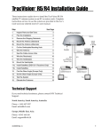
1
Installation Guide
TracVision M9
TracVision M9
Standard Configuration
TracVision M9 Installation Guide
Standard Configuration with Master Control Unit (MCU)
These instructions explain how to install the TracVision M9 satellite TV antenna system on a
vessel. Complete instructions on how to use the system are provided in the User’s Guide.
Installation Steps
1. Inspect Parts and Get Tools...3
8. Wire the Receiver(s) and MCU...10
2. Plan the Antenna Installation...4
9. Connect Power...11
3. Plan the MCU Installation...5
10. Mount the MCU...12
4. Prepare the Antenna Site...6
11. Select Satellites...13
5. Wire the Antenna...7
12. Calibrate the Internal Sensor...14
6. Mount the Antenna...8
13. Educate the Customer...16
7. Remove the Restraints...9
Who Should Install the System?
To ensure a safe and effective installation, KVH recommends that a KVH-authorized marine
technician install the TracVision antenna. KVH-authorized technicians have the tools and
electronics expertise necessary to install the system. To find a technician near you, visit
www.kvh.com/wheretogetservice.
Antenna LNB Types
The installation process differs slightly depending on the type of LNB (low noise block) that is
installed in the antenna (circular or linear). These differences are noted throughout this manual.
Appendix C on page 25 notes the type of LNB required for each region and satellite.
Technical Support
If you need technical assistance, please contact KVH Technical Support:
North/South America, Australia:
Phone: +1 401 847-3327
E-mail: [email protected]
Europe, Middle East, Asia:
Phone: +45 45 160 180
E-mail: [email protected]
KVH, TracVision, and the unique light-colored dome with contrasting baseplate are registered trademarks of KVH Industries, Inc.
All other trademarks are property of their respective companies. The information in this document is subject to change without notice.
No company shall be liable for errors contained herein. © 2007 KVH Industries, Inc., All rights reserved. 54-0418 Rev. C
1
1 Inspect Parts and Get Tools
Before you begin, follow these steps to make sure
you have everything you need to complete the
installation.
Figure 1: TracVision M9 System Components
Antenna
a. Unpack the box and ensure it contains
everything shown on the Kitpack Contents
List. Save the packaging for future use.
Radome
IMPORTANT!
Always lift the antenna by the baseplate and
never by the radome or any portion of the
internal antenna assembly (see Figure 1).
b. Carefully examine all of the supplied parts to
ensure nothing was damaged in shipment.
c. Gather all of the tools and materials listed
below. You will need these items to complete
the installation.
•
Flat-head and Phillips-head screwdrivers
•
Electric drill and 1/2" (13 mm) and #29
drill bits
•
17 mm socket wrench
•
9/16" open-end wrench
•
Light hammer and center punch
•
Adhesive tape
•
Scriber or pencil
•
Wire strippers
•
15-amp quick-tripping circuit breaker
•
RG-6 or RG-11 RF coax cable(s) with
Snap-N-Seal® F-connectors for
connecting the antenna to the receiver(s)
(see Step 4e on page 6 to determine the
number and type of cables required)
•
Connector installation tool (Augat IT1000
- KVH part #19-0242)
•
Power cable for connecting vessel power
to the MCU (see Figure 2)
•
Satellite TV receiver and TV
Baseplate
Connectors
(w/Logo Plate)
MCU (Master Control Unit)
Display
Buttons
Figure 2: Power Cable Guidelines
Cable Length
Use Cable Gauge
< 40 ft (12 m)
12AWG (4mm2)
40-70 ft (12-21 m)
10AWG (6mm2)
3
2 Plan the Antenna Installation
Before you begin, consider the following antenna
installation guidelines:
•
•
•
•
•
•
•
•
Figure 3: Blockage from Obstruction
Minimize blockage. The antenna requires a
clear view of the sky to receive satellite TV
(see Figure 3). The fewer obstructions, the
better the system will perform.
Make sure the mounting surface is wide
enough to accommodate the antenna’s base
(see Figure 4). Also make sure it is flat, level,
strong enough to support the antenna’s
weight (85 lbs, 38.6 kg), and rigid enough to
withstand vibration.
Be sure to preserve enough free space outside
the access hatch to allow a technician to
remove the hatch and perform maintenance.
Blocked!
Look angle
Antenna
Mast
Vessel Platform
Figure 4: Antenna Dimensions
Select a location that is as close as possible to
the intersection of the vessel’s fore-and-aft
centerline and midships.
Select a location that is not too high above the
waterline. Limit the height above the
waterline to less than 1/2 the vessel’s length.
Side View
38.86"
(98.7 cm)
Do not mount the antenna at the same level
as the radar because the radar’s energy might
overload the antenna. Ideally, you should
mount the antenna 4 ft (1.2 m) above and 4 ft
(1.2 m) away from the radar.
Select a location that is at least 4 ft (1.2 m)
away from any magnetized materials, large
ferrous masses, cranes, engines, derricks,
other antennas, devices with DC motors,
electric winches, high-amperage cables, or
battery banks. The antenna’s internal
compass sensor performs best in a benign
magnetic environment.
If you are mounting the antenna on a steel
vessel, use an aluminum, brass, plastic, or
wood platform (NOT steel or iron) to position
the antenna at least 4 ft (1.2 m) above and 6 ft
(1.8 m) away from the steel surface.
Access Hatch
17"
(43.2 cm)
4x ø.50"
(4x ø13 mm)
ø35"
(ø88.9 cm)
12"
(30.5 cm)
Bottom View
6"
(15.2 cm)
6"
(15.2 cm)
12"
(30.5 cm)
FWD
4
3 Plan the MCU Installation
Before you begin, consider the following MCU
installation guidelines:
•
Select an MCU mounting location in a dry,
well-ventilated area belowdecks away from
any heat sources or salt spray.
•
Be sure the MCU’s front panel will be easily
accessible to the user. The owner will use the
MCU’s buttons to control the antenna.
•
Be sure to leave enough room at the MCU’s
rear panel for connecting the cables (see
Figure 5 for MCU dimensions).
•
Since the supplied data/power cable is 100 ft
(30 m) long, the MCU should be located
within 100 ft (30 m) of the antenna.
•
The kitpack contains parts for mounting the
MCU either to a horizontal surface (using
Velcro) or to a vertical surface (using the
supplied flush mount bracket).
Figure 5: MCU Dimensions
Top View
9.18"
(233.2 mm)
Front View
Prepare the MCU Mounting Site
(Flush Mount only)
NOTE: Skip this step if you plan to mount the MCU
to a horizontal surface instead.
a. Using the MCU flush mounting template
provided at the end of this manual, mark and
cut out a hole in the mounting surface to
accommodate the flush mount bracket (see
Figure 6).
b. Using the same template, mark the locations
for the four MCU mounting holes.
c. Using a #29 drill bit, drill a 0.136" (3.45 mm)
hole at the four mounting hole locations.
Later, you will mount the MCU using four #8
screws.
0.66"
(16.7 mm)
2.52"
(64.1 mm)
8.1"
(205.7 mm)
Figure 6: MCU Mounting Holes Layout
.63"
(16 mm)
7.62"
(194 mm)
8.87"
(225 mm)
1.83"
3.08" (46 mm)
(78 mm)
.63"
(16 mm)
.136" ( 3.45 mm)
Mounting Hole (x4)
5
4 Prepare the Antenna Site
Once you have identified a suitable antenna
mounting site, according to the guidelines
provided in Step 2, follow these steps to drill the
mounting holes and cable access hole to prepare
the site for installation.
Figure 7: Antenna Mounting Holes Layout
a. Unfold the antenna mounting template
(supplied in the Customer Welcome Kit) and
place it onto the mounting surface. Make sure
the “FWD” (forward) arrow points toward
the bow and is parallel to the vessel’s
centerline (see Figure 7).
NOTE: You don’t need to mount the antenna
exactly on the vessel’s centerline, but the
antenna’s forward arrow must be parallel to it.
b. Use the template to mark the locations for the
four mounting holes on the mounting
surface.
c. Drill a 1/2" (13 mm) hole at the four
mounting hole locations you marked in
Step 4b. Later, you will insert four M10 bolts
from below to secure the antenna to the
mounting surface.
d. Mark a location for the cable access hole,
either in the center of the antenna mounting
hole pattern or in an area aft of the antenna.
Later, you will route the data/power and RF
cables through this hole and into the vessel.
IMPORTANT!
If you wish to route the cables through the
bottom of the antenna’s baseplate, rather than
connecting at the side, you will need to
modify the antenna’s baseplate. See
Appendix A on page 19 for details.
e. Drill the cable access hole in the location you
marked in Step 4d. Be sure to size the hole
appropriately to accommodate the data/
power cable and all required RF cables (see
Figure 8 and Figure 9 to determine the
number and type of RF cables required).
Smooth the edges of the hole to protect the
cables.
6
Figure 8: Number of RF Coax Cables Required
Connecting to:
# RF Cables
System with Dual LNB
1 receiver
1
2 or more receivers
2*
System with Quad LNB (Europe Only)
1 receiver
1
2 receivers
2
3 receivers
3
4 or more receivers
4**
* Multiswitch required for 3 or more receivers.
** Multiswitch required for 5 or more receivers.
See Appendix B on page 23 for details.
Figure 9: RF Cable Guidelines
Cable Length
Use Cable Type
≤ 75 ft (23 m)
RG-6
> 75 ft (23 m)
RG-11
5 Wire the Antenna
Follow these steps to connect the data/power
and RF cables to the antenna.
Figure 10: Antenna Connectors
IMPORTANT!
If you wish to route the cables through the
bottom of the antenna’s baseplate, rather than
connecting at the side, see Appendix A on
page 19 for supplemental instructions.
a. Route the data/power and RF cables
belowdecks through the cable access hole.
Leave an adequate service loop,
approximately 8" (20 cm) of slack, in the
cables for easy serviceability. Later, you will
connect the data/power cable to the MCU
and the RF cable(s) to the receiver(s).
b. Position the antenna in place over the
mounting holes with the baseplate’s
connectors (see Figure 10) facing the stern.
c. Connect the data/power cable to the antenna
(see Figure 11 and Figure 12); hand-tighten.
Connectors
Figure 11: Data/Power Cable Connections
MCU
Antenna
F-type Connector
N-type Connector
Figure 12: Antenna Baseplate Cable Connections
RF3
RF1
Data/
Power
RF2
RF4
IMPORTANT!
Be sure to properly align the data/power
cable with the antenna’s baseplate connector
before tightening. Connecting the cable at an
angle may damage the cable’s center tines.
d. Using a 9/16" wrench, connect the RF cable(s)
to the antenna. If you need to connect only
one RF cable, connect the cable to the
antenna’s RF1 connector (see Figure 12).
Connect any additional RF cables to the RF2,
RF3, and RF4 connectors.
Figure 13: Rear Logo Plate Installed
TIP: If you connect two or more RF cables, label
both ends of each cable to match the connector.
This will make it easier to identify the cables later.
e. Place the rear logo plate over the cables, so
each cable exits the proper opening (see
Figure 13). Using six M4 screws, attach the
logo plate to the baseplate.
M4 Screw (x6)
RF1 Cable
Data/Power Cable
7
6 Mount the Antenna
Follow these steps to mount the antenna to the
mounting surface.
a. Place the antenna baseplate over the holes
drilled in the mounting surface.
b. Make sure the four holes in the baseplate line
up with the four holes in the mounting
surface. Also make sure the connectors face
the stern.
c. At each of the four baseplate mounting holes,
place an M10 lock washer and flat washer on
an M10 bolt and insert the bolt into the hole
from below (see Figure 14).
IMPORTANT!
Make sure the mounting screws do not
extend further than 0.4" (10 mm) into the
antenna’s baseplate. Inserting the screws any
further will damage the antenna.
d. Tighten all four bolts until the four rubber
feet are bottomed against the mounting
surface.
IMPORTANT!
Do not block the four small drain holes in the
bottom of the antenna. These drain holes
ensure that any moisture within the antenna
will be able to escape.
8
Figure 14: Mounting the Antenna (Side View)
10 mm max.
Antenna Base
Mount Surface
M10 Flat Washer (x4)
M10 Lock Washer (x4)
M10 x 50 mm Bolt (x4)
7 Remove the Restraints
Inside the antenna, three heavy-duty tie-wraps
prevent the antenna assembly from moving
during shipment. Follow these steps to remove
these shipping restraints.
Figure 15: Removing the Radome
a. Remove the eight #10-32 Phillips-head screws
securing the radome to the baseplate (see
Figure 15). Carefully lift the radome straight
up until clear of the antenna assembly and set
it aside in a safe place.
#10-32 Screw (x8)
TIP: If you keep the radome topside, secure it with
a lanyard to prevent it from falling overboard.
b. Unfasten the two tie-wraps securing the
reflector to the antenna frame (see Figure 16).
To unfasten the tie-wraps, release the tab
with a flat-head screwdriver.
c. Unfasten the tie-wrap securing the antenna
frame to the sensor bracket (see Figure 17).
d. Save the tie-wraps for future use; the
customer will need to reinstall them if he/she
needs to relocate or reship the antenna.
Figure 16: Locations of Shipping Restraints
Tie-wrap
Tie-wrap
e. Reinstall the radome onto the antenna. Secure
in place with the eight #10-32 screws you
removed in Step 7a.
f.
Install a protective plastic screw cap
(supplied in the kitpack) over each radome
screw.
Tie-wrap
Figure 17: Close-up of Antenna Frame Shipping Restraint
Sensor Bracket
Tie-wrap
Frame
9
8 Wire the Receiver(s) and MCU
Follow these steps to connect the antenna to the
belowdecks equipment.
Figure 18: Receiver Wiring
IMPORTANT!
If you wish to connect three or more receivers
to the antenna, see Appendix B on page 23.
Antenna
NOTE: System wiring diagrams are provided in
Appendix F on page 31.
MCU
a. If you are connecting two receivers to the
TracVision system, decide which receiver
will be the primary receiver. The primary
receiver controls satellite selection.
NOTE: The secondary receiver will only be able to
select a channel carried on the satellite that is
currently selected on the primary receiver.
Data/Power
Secondary Receiver - Optional
TV ANT/CABLE IN
RF2
R
L
OUT TO TV
SATELLITE IN
PHONE JACK
Primary Receiver (controls satellite selection)
TV ANT/CABLE IN
RF1
R
L
OUT TO TV
SATELLITE IN
AUDIO
VIDEO
S-VIDEO
PHONE JACK
SATELLITE IN
Gnd To MCU
DC Return (-)
Be sure all receivers are grounded properly.
Connect a ground wire from the chassis of
each receiver to the MCU’s DC return. This
will ensure all system grounds are the same
potential.
Figure 19: MCU Rear Panel
d. Connect the receiver(s) to the customer’s
television(s). Follow the instructions in the
receiver’s manual.
10
S-VIDEO
Gnd To MCU
DC Return (-)
IMPORTANT!
e. Connect the data/power cable from the
antenna to the “Output to Antenna” jack on
the MCU (see Figure 19). Do not overtighten
the connection; finger-tight is sufficient.
VIDEO
SATELLITE IN
b. Connect the RF1 cable from the antenna to
the “Satellite In” jack on the primary receiver
(see Figure 18).
c. If you are connecting two receivers, connect
the RF2 cable from the antenna to the
“Satellite In” jack on the secondary receiver.
AUDIO
Output to Antenna
9 Connect Power
Follow these steps to connect power to the MCU.
The MCU supplies power to the antenna.
a. Before you begin, disconnect vessel power.
Figure 20: Ferrite Coil Clamped onto Power Cable
Ferrite Coil
CAUTION
For your own safety, disconnect vessel power
and make sure the circuit is dead before you
connect any power wires.
b. Connect a power cable to 24 VDC (2.5 amps)
vessel power (for cable specifications, see
Figure 2 on page 3). Power supplied to the
antenna MUST NOT fall below 18 VDC or
exceed 30 VDC.
NOTE: If a 24 VDC power supply is not available,
install an AC/DC converter that supplies 24 VDC
(KVH part #19-0488 or equivalent).
Figure 21: Power Plug
Terminal Screw (x2)
c. KVH recommends you install a 15-amp
circuit breaker between power and the MCU.
The MCU does not have an on/off switch.
d. Install the ferrite coil, supplied in the kitpack,
onto your vessel power cable to help reduce
conducted emissions. Make two loops in the
cable and clamp the coil around the loops
(see Figure 20). This ferrite coil must be
installed to comply with the CE standard.
e. Find the plastic power plug supplied in the
kitpack (see Figure 21). Insert your vessel
power wires into the plug’s power (+) and
ground (-) terminals. Tighten the plug’s
terminal screws to secure the wires in place.
f.
Plug the power connector plug into the
“Power In” jack on the MCU. Secure in place
with the two retaining screws.
g. Connect the MCU ground wire (see
Figure 22) to a suitable ground point.
Retaining Screw (x2)
Power
Ground
Figure 22: MCU Power Connection
Power In
MCU Ground Wire
11
10 Mount the MCU
In Step 3, you identified a suitable MCU
mounting location. Now follow these steps to
mount the MCU using one of the following
options:
Option 1 - Velcro mount to a horizontal surface
Figure 23: Velcro Mounting
Fabric Strip (x4)
Option 2 - Flush mount to a vertical surface
Option 1 - Velcro Mount
Hook Disk (x4)
a. Clean the bottom of the MCU and the
mounting surface using a mild detergent.
b. Peel the backing from the four supplied
Velcro fabric squares and stick them to the
bottom corners of the MCU (see Figure 23).
c. Position the four Velcro hook disks onto the
mounting surface. Drill screw holes for the
disks and secure in place with #4-24 screws.
#4-24 Screw (x4)
Figure 24: Flush Mount Bracket
d. Press the MCU firmly into place so the
fabric’s loop material engages the hook disks.
Option 2 - Flush Mount
a. At the two holes in the bottom of the MCU,
place a #6 flat washer on a #6-32 screw and
insert the screw from below (see Figure 24).
Do not tighten the screws yet.
b. Slide the flush mount bracket backward onto
the MCU until the two notches in the bracket
engage the screws at the bottom of the MCU.
c. Tighten the screws to secure the bracket to
the MCU.
d. In Step 3 on page 5, you cut out the mounting
hole in the mounting surface. Insert the MCU
and bracket assembly into this mounting hole
and secure in place with four #8 screws and
washers (see Figure 25).
#6-32 x 1/2" Screw
and Washer (x2)
Figure 25: Flush Mounting the MCU to a Vertical Surface
#8 Screws and
Washers (x4)
12
11 Select Satellites
Follow these steps to turn on the system and set it
up for the desired pair of satellites.
a. Ensure the antenna has a clear, unobstructed
view of the sky.
Figure 26: Satellite Selection Menus on MCU
Menu
b. Apply power to the receiver(s), TV(s), and
MCU. Wait two minutes for system startup.
c. Press the center MENU button on the MCU
to access the onscreen menu (see Figure 26).
Install Satellite?
Yes
Next
Return
d. At “Install Satellite?”, press YES.
e. At “Install A <SAT NAME>”, press NEXT
until the display shows the first (primary)
satellite you want to select. Then press YES.
(See Appendix C on page 25 for a list of
available satellites.)
f.
Install A <SAT NAME>
Yes
Next
Cancel
Press NEXT until desired satellite shown
Install B <SAT NAME>
Yes
Next
Cancel
NOTE: If you don’t find the satellite you want,
you can set up a user-defined satellite (USER 1 or
USER 2). See Appendix D on page 26.
Installing sats
Please wait
Repeat Step 11e to select the second satellite.
If you want to set up the antenna to track just
one satellite, select “None” instead.
<SAT NAME1> and
<SAT NAME2> installed
g. At “Restart Antenna?”, press YES. Wait two
minutes while the antenna restarts.
h. (Linear systems only) Set up the receiver(s)
for the same satellites, and in the same order,
that you set them up in the antenna:
Antenna
Receiver
DiSEqC
Sat. A
Alternative 1 or A
DiSEqC 1
Sat. B
Alternative 2 or B
DiSEqC 2
Press NEXT Until desired satellite shown
Restart antenna?
Yes
No
13
12 Calibrate the Internal Sensor
The antenna’s internal compass sensor is
calibrated at the factory for a perfect-world
environment. However, hard and soft iron effects
on your vessel can distort the magnetic field
around the antenna, causing errors in the
sensor’s reported heading. To compensate for
these magnetic distortions, follow these steps to
calibrate the internal sensor.
Turn On Autocalibration
Follow these steps to turn on the system’s
Autocalibration function. The Autocalibration
function will allow the sensor to calibrate itself
automatically.
a. Press the center MENU button on the MCU
to access the onscreen menu (see Figure 27).
Figure 27: Turning On Autocalibration at the MCU
Menu
Install Satellite?
Yes
Next
Return
Until “Operations Mode” shown
Operations Mode?
Yes
Next
Return
Get Antenna Status?
Yes
Next
Return
Until “Control Compass” shown
b. At “Install Satellite?”, press NEXT until the
display shows “Operations Mode?” Then
press YES.
Control compass?
Yes
Next
Return
c. At “Get Antenna Status?”, press NEXT until
the display shows “Control Compass?” Then
press YES.
Set Autocal on/off?
Yes
Next
Return
d. At “Set Autocal on/off?”, press YES.
e. At “Autocal is: OFF”, press ON.
f.
At “Autocal is: ON”, press RETURN.
Run the Autocalibration Function
Follow these steps to steer the vessel through a
complete circle to ensure the Autocalibration
function effectively calibrates the sensor.
NOTE: If the antenna is installed on a large vessel,
such as a tanker or cargo ship, you may omit this step.
Simply leave the Autocalibration function set to ON.
a. Select a calm day and navigate the vessel to a
clear area. Excessive pitching and rolling can
distort calibration data.
b. Apply power to the TracVision system.
c. Just before you begin, note the vessel’s
heading.
14
Autocal is: OFF
On
Return
Off
On
Autocal is: ON
Return
Off
12 Continued...
d. Steer the vessel at a slow, steady speed
through a complete circle that takes at least
two minutes to complete (see Figure 28). Use
the heading you noted in Step c to confirm
when you have completed a full circle.
Figure 28: Running Autocalibration
2 Minutes
Check the Calibration Score
Once you have completed the circle, follow these
steps to check the calibration “score.”
a. Press the center MENU button on the MCU
to access the onscreen menu.
b. At “Install Satellite?”, press NEXT until the
display shows “Operations Mode?” Then
press YES.
30 Seconds
1 Minute,
30 Seconds
c. At “Get Antenna Status?”, press NEXT until
the display shows “Control Compass?” Then
press YES.
d. At “Set Autocal on/off?”, press NEXT until
the display shows “Get Cal Score?” Then
press YES.
1 Minute
e. The display shows the score for the
calibration you performed (see Figure 29).
f.
If Accuracy = “BAD CAL”:
Recalibrate the sensor by navigating through
an additional circle. Repeat until you achieve
a suitable accuracy rating.
g. If Mag. Environment = “POOR” or “BAD”:
Check the area around the antenna for
materials that might cause magnetic
interference. Relocate the materials, if
possible, or relocate the antenna to a more
favorable magnetic environment (see Step 2
on page 4 for details). Then clear the
calibration score (see Appendix E on page 30)
and recalibrate the sensor.
h. Press any button. The display returns to the
“Get Cal score?” screen.
i.
Press RETURN until you exit the menu.
NOTE: The Autocalibration function turns off
automatically once the system achieves a good
calibration score.
Figure 29: Calibration Score Example
Magnetic
Environment
Accuracy
Rating
ACC
MagEnv
CAL<1° GOOD
Calibration
Number
Cal#
1
Data Field
Description
Accuracy
Rating
Degree of accuracy the
sensor will provide
(CAL<1º = within 1º)
Magnetic
Environment
Quality of the antenna’s
installation site
Calibration
Number
Number of times the
sensor was calibrated
15
13 Educate the Customer
The installation process is complete!
Figure 30: Example of Satellite Blockage
Before you depart the vessel, test the system to
verify the antenna works properly. Then give the
Customer Welcome Kit to the customer and
explain how to use the system. Also be sure the
customer understands the following:
•
Keep the radome installed on the antenna at
all times. The radome protects the antenna’s
moving parts from wind, rain, and debris.
WARNING
TracVision
It is dangerous to watch TV while piloting a
vessel. The TracVision system is intended as
a passenger entertainment product only.
16
•
The antenna must have a clear view of the
sky to receive satellite TV. Common causes of
blockage include trees, buildings, bridges,
and onboard equipment (see Figure 30).
•
Heavy rain or snow may temporarily
interrupt reception.
•
Clean the antenna regularly. Dirt buildup on
the radome can affect reception.
•
The vessel must be located within the
selected satellite’s coverage area to receive its
satellite TV signals. To view satellite coverage
maps, visit www.kvh.com/footprint.
•
Please register the system with KVH. The
registration process is quick, easy, online, and
ensures the best possible service from KVH.
Visit www.kvh.com/register or refer to the
Product Registration Form for details.
•
Refer to the User’s Guide for complete
operation instructions and troubleshooting
information.
Appendices
This section provides supplemental instructions for special or advanced configurations. It also
provides system wiring diagrams and a mounting template for the belowdecks equipment.
Contents
A. Optional Bottom Cable Entry Kit...19
B. Connecting Multiple Receivers...23
C. Satellite Library...25
D. User-Defined Satellites...26
E. Clearing the Calibration Score...30
F. Wiring Diagrams...31
MCU Flush Mounting Template...35
17
A Optional Bottom Cable Entry Kit
If you wish to route the system cables through
the bottom of the antenna’s baseplate, rather than
connect the cables at the side of the baseplate,
follow these steps to modify the antenna for
bottom cable entry. Figure 31 shows the relevant
parts of the antenna baseplate; refer to this figure
throughout the procedure.
Remove the Radome and Restraints
1. Perform Steps 7a through 7d on page 9 to
remove the antenna’s radome and shipping
restraints. You will need to rotate the antenna
assembly by hand to access various parts of
the baseplate.
Appendix
Figure 31: Interior of Antenna Baseplate (Antenna Not Shown)
Baseplate Hatch
Cable Brackets
Original Location
For Cable PCB
Alternate Location
For Cable PCB
Small Cover Plate
IMPORTANT!
Once you have removed the restraints,
handle the antenna very carefully. With the
restraints removed, the internal antenna
assembly rotates freely and, if not handled
properly, can damage the limit switch.
Figure 32: Cable PCB in Original Location
Relocate the Cable PCB
#4-40 Screw (x5)
1. Remove the tie-wrap securing the cable PCB
(printed circuit board) wires to the baseplate
access hatch (see Figure 32).
2. Remove the five #4-40 screws, washers, and
nuts securing the cable PCB to the access
hatch (see Figure 32).
3. Attach the cable PCB to the alternate cable
PCB bracket (see Figure 33) using the five
#4-40 screws and washers supplied in the
kitpack. Apply a small amount of Loctite
threadlocker to the screw threads before
securing.
Tie-wrap
Figure 33: Cable PCB in Alternate Location
Original Location
Alternate Location
#4-40 Screw (x5)
19
A Continued...
Seal the Original Cable PCB Location
Figure 34: Large Cover Plate and Gasket
1. Peel off the paper backing from the large
cover plate gasket supplied in the kitpack.
Attach the gasket to the supplied cover plate,
making sure all holes are aligned. Also make
sure all of the holes will align with the holes
at the original PCB location, gasket side
facing down.
2. Position the large cover plate and gasket
(gasket side facing down) over the original
cable PCB location. Secure in place with the
five #4-40 screws and washers you removed
earlier. Apply a small amount of Loctite
threadlocker to the screw threads before
securing (see Figure 34).
#4-40 Screw (x5)
Large Cover Plate
and Gasket
Prepare the Bottom Cable Access Hole
1. Remove the two M4 screws from the small
cover plate and gasket inside the antenna
baseplate. Remove the small cover plate and
gasket (see Figure 35).
2. Peel off the paper backing from the rubber
seal and carefully attach the rubber seal to the
underside of the baseplate, ensuring a good
seal around the rim of the bottom cable access
hole (see Figure 36).
Figure 35: Small Cover Plate and Gasket
Small Cover Plate
and Gasket
Antenna Assembly
M4 Screw (x2)
Figure 36: Rubber Seal on Underside of Baseplate
Rubber Seal
Note: You will route these
cables later in the process
20
A Continued...
Route and Secure the Cables
Figure 37: Cable Brackets on Inside Rim of Baseplate
1. Remove the four M4 screws securing the
cable brackets to the inside rim of the
baseplate (see Figure 37). Remove and save
the cable brackets.
2. Route the data/power (F-type connector end)
and RF cables belowdecks through the cable
access hole. Leave an adequate service loop,
approximately 8" (20 cm) of slack, in the
cables for easy serviceability. Later, you will
connect the data/power cable to the MCU
and the RF cable(s) to the receiver(s).
3. Route the N-type connector end of the data/
power cable (see Figure 38) through the
baseplate’s bottom cable access hole. Connect
the data/power cable to the center connector
on the cable PCB (see Figure 39).
IMPORTANT!
M4 Screw (x4)
Figure 38: Data/Power Cable Connections
MCU
Antenna
F-type Connector
N-type Connector
Figure 39: Cable Connections on PCB
Be sure to properly align the data/power
cable with the PCB connector before
tightening. Connecting the cable at an angle
may damage the cable’s center tines.
4. Route the RF cable(s) through the baseplate’s
bottom cable access hole. Using a 9/16"
wrench, connect the RF cable(s) to the cable
PCB (see Figure 39). If you need to connect
only one RF cable, connect the cable to the
RF1 connector. Connect any additional RF
cables to the RF2, RF3, and RF4 connectors.
See Step 4e on page 6 to determine the
number of RF cables required.
RF4 RF2 Data/ RF1 RF3
Power
Figure 40: Cables Secured by Brackets
TIP: If you connect two or more RF cables, label
both ends of each cable to match the connector.
This will make it easier to identify the cables later.
5. Secure the data/power and RF cables to the
inside rim of the baseplate, using the two
cable brackets. Secure the brackets in place
using the four M4 screws you removed
earlier (see Figure 40).
M4 Screw (x4)
21
A Continued...
6. Attach the supplied cable exit shroud over
the cable access hole inside the baseplate,
using the two M4 screws you removed earlier
from the cover plate (see Figure 41).
Replace the Logo Plate
Figure 41: Cable Exit Shroud Installed Over Cables
Cable Exit Shroud
1. Attach the supplied blank logo plate using six
M4 screws (see Figure 42).
2. Discard the old logo plate, or save it in case
you need to change the cable routing in the
future.
The baseplate conversion process is complete!
Complete the remaining system installation steps
starting with Step 6 on page 7.
M4 Screw (x2)
Figure 42: Blank Logo Plate (No Cable Slots)
Blank Logo Plate
M4 Screw (x6)
22
B Connecting Multiple Receivers
Appendix
IMPORTANT!
Only antennas equipped with a circular dual
LNB or a linear quad LNB can support more
than two receivers. Antennas equipped with
a linear dual LNB support only two receivers.
Figure 43: Multiswitch Wiring - Antenna with Circular Dual LNB
Antenna with Circular Dual LNB
Antenna
(North American systems only)
To connect three or more receivers, follow these
steps to install an active (powered) multiswitch
between the antenna and the receivers.
RF1
NOTE: You can purchase an active multiswitch,
Channel Master model 6314IFD, from KVH (order
part #19-0123).
1. Connect the RF1 cable from the antenna to
the “RHCP +13V” jack on the multiswitch
(see Figure 43).
2. Connect the RF2 cable from the antenna to
the “LHCP +18V” jack on the multiswitch.
3. Connect the receivers to the individual
outputs of the multiswitch.
4. Terminate any unused multiswitch outputs
with 75 ohm DC blocks (Channel Master
#7184, Radio Shack #15-1259, or equivalent).
RF2
Data/Power
RHCP
+13V
LHCP
+18V
DC In
MCU
Multiswitch
Gnd To MCU
DC Return (-)
Receiver #1
TV ANT/CABLE IN
R
AUDIO
VIDEO
S-VIDEO
PHONE JACK
VIDEO
S-VIDEO
PHONE JACK
VIDEO
S-VIDEO
PHONE JACK
VIDEO
S-VIDEO
PHONE JACK
SATELLITE IN
Receiver #2
IMPORTANT!
Be sure the multiswitch is properly grounded.
With the multiswitch grounded, you do not
need to ground the individual receivers.
L
OUT TO TV
SATELLITE IN
TV ANT/CABLE IN
R
L
OUT TO TV
SATELLITE IN
AUDIO
SATELLITE IN
Receiver #3
TV ANT/CABLE IN
IMPORTANT!
R
L
OUT TO TV
SATELLITE IN
AUDIO
SATELLITE IN
(DIRECTV only) Multiswitches block a
receiver’s 22 KHz tone that the antenna needs
to switch satellites automatically. Therefore,
the customer will need to manually switch
satellites using the buttons on the MCU.
Receiver #4
TV ANT/CABLE IN
R
L
OUT TO TV
SATELLITE IN
AUDIO
SATELLITE IN
23
B Continued...
Antenna with Linear Quad LNB
Figure 44: Receiver Wiring - Antenna with Linear Quad LNB
(European systems only)
Follow these steps to connect three or four
receivers directly to the antenna.
Antenna
NOTE: If you need to connect more than four
receivers to the TracVision system, install an active
multiswitch that generates a 22 KHz tone (such as
Spaun model 5602NF - KVH part #19-0413).
Connect the multiswitch in accordance with the
manufacturer’s instructions.
1. Decide which receiver will be the primary
receiver. The primary receiver will control
satellite selection.
NOTE: The additional receivers will be able to
select any channel carried on the satellite that is
currently selected on the primary receiver.
2. Connect the RF1 cable from the antenna to
the “Satellite In” jack on the primary receiver
(see Figure 44).
MCU
Data/Power
Receiver #4
TV ANT/CABLE IN
RF4
R
L
OUT TO TV
SATELLITE IN
AUDIO
VIDEO
S-VIDEO
PHONE JACK
SATELLITE IN
Gnd To MCU
DC Return (-)
Receiver #2
TV ANT/CABLE IN
RF2
R
L
OUT TO TV
SATELLITE IN
3. Connect the RF2 cable from the antenna to
the “Satellite In” jack on the second receiver.
AUDIO
VIDEO
S-VIDEO
PHONE JACK
SATELLITE IN
Gnd To MCU
DC Return (-)
4. Connect the RF3 cable from the antenna to
the “Satellite In” jack on the third receiver.
Primary Receiver (Controls satellite selection)
TV ANT/CABLE IN
5. Connect the RF4 cable from the antenna to
the “Satellite In” jack on the fourth receiver.
RF1
R
L
OUT TO TV
SATELLITE IN
AUDIO
VIDEO
S-VIDEO
Gnd To MCU
DC Return (-)
IMPORTANT!
Be sure all receivers are grounded properly.
Connect a ground wire from the chassis of
each receiver to the MCU’s DC return. This
will ensure all system grounds are the same
potential.
24
PHONE JACK
SATELLITE IN
Receiver #3
TV ANT/CABLE IN
RF3
R
L
OUT TO TV
SATELLITE IN
AUDIO
VIDEO
S-VIDEO
PHONE JACK
SATELLITE IN
Gnd To MCU
DC Return (-)
C Satellite Library
Appendix
The TracVision M9 antenna can track a variety of
DVB-compatible and DSS (DIRECTV) satellites.
Most popular satellites are programmed in the
antenna’s library (see the tables below).
North America
Europe
Standard Circular Dual LNB Required
Linear Quad LNB Required
Satellite, Longitude
Name in Library
Satellite
Name in Library
DIRECTV, 72°W
DSS_72
Astra 1, 19.2°E
ASTRA1
DIRECTV, 101°W
DSS_101
Astra 2N, 28.2°E
ASTRA2N
DIRECTV, 110°W
DSS_110
Astra 2S, 28.2°E
ASTRA2S
DIRECTV, 119°W
DSS_119
Hispasat, 30.0°W
HISPASAT
EchoStar, 61°W
ECHO_61
Hotbird, 13.0°E
HOTBIRD
EchoStar, 110°W
ECHO_110
Hotbird WB, 13.0°E
HOTBIRDWB
EchoStar, 119°W
ECHO_119
Sirius, 5.0°E
SIRIUS
EchoStar, 148°W
ECHO_148
Thor, 0.8°W
THOR
ExpressVu, 82°W
EXPRESSVU
Arabsat, 26°E
ARABSAT
ExpressVu, 91°W
EXPRESSTV
Nilesat, 7°W
NILESAT
Turksat 1C, 42°E
TURKSAT1C
Eutelsat W3A, 7°E
EUTEL_W3A
Asia
Standard Circular Dual LNB Required
Satellite
Name in Library
Mexico
Asiasat 4, 122.2°E
ASIASAT
Linear Dual LNB Required
Sinosat 1*, 110.5°E
SINOSAT
Latin America
Galaxy Circular Dual LNB Required
Satellite
Name in Library
Galaxy 3C, 95°W
GALAXY3CN
Satellite
Name in Library
PAS 9, 58°W
PAS_9
Australia & New Zealand
Linear Quad LNB Required
Satellite
Name in Library
Optus B1*, 160°E
OPTUS_B1
Optus C1, 156°E
OPTUS_C1
* Special LNB required. Call KVH at 1-401-847-3327.
25
D User-Defined Satellites
The satellite library in the TracVision antenna
includes two slots for user-defined satellites
(USER 1 and USER 2). You can program one or
both of these library slots for any satellite you
wish that is not already set up in the library.
Appendix
Figure 45: Technician Programming the Antenna
Connect a Laptop to the Antenna
To program your user-defined satellite(s), you
first need to connect a Windows® laptop
computer to the TracVision system and start
Windows HyperTerminal.
TIP: If you are a KVH-authorized technician, you can
use the KVH Flash Update Wizard instead of
HyperTerminal. Enter commands in the wizard’s
“Antenna Comms” window. You do not need to flash
the antenna to enter commands.
1. Turn off the TracVision antenna.
Figure 46: Maintenance Port on MCU
2. Using a straight PC serial data cable, connect
your laptop to the DB9 Maintenance port on
the back of the MCU (see Figure 46).
NOTE: If your computer does not have a DB9 serial
COM port, you can use the USB-to-RS232 adapter
manufactured by IOGear (IOGear part number
GUC232A) or Belkin (Belkin part number F5U109).
3. Open Windows HyperTerminal and establish
the following settings for your COM port (see
Figure 47):
•
•
•
•
•
Bits per second: 9600
Data bits: 8
Parity: None
Stop bits: 1
Flow control: None
TIP: To view characters on the screen as you type, set
up HyperTerminal to echo typed characters. Select
“Properties” from the File menu; select “ASCII
Setup” at the Settings tab; then select “Echo typed
characters locally” at the ASCII Setup window.
26
Maintenance Port
Figure 47: HyperTerminal Settings
Maintenance Port
D Continued...
4. Apply power to the TracVision antenna. Data
should soon be scrolling in your
HyperTerminal window (see Figure 48). If no
data appears, check your connections and
make sure you’re using the correct COM
port.
Figure 48: Antenna Data Scrolling in Window
5. Follow the steps in the next section to
program the antenna via the HyperTerminal
window.
Program Your User-Defined Satellites
To configure a user-defined satellite, you will
need to program into the antenna the following
information about the satellite (see Figure 49):
•
Satellite name
•
Satellite longitudinal position
•
Transponder information for all
combinations of polarization and band:
• vertical high
• vertical low
• horizontal high
• horizontal low
OR
• right
• left
•
Frequency
•
Symbol rate
•
FEC code rate
•
Network ID
•
Decoder type
Figure 49: Identifying a Linear Satellite
Name
Longitude
Decoder type
Vertical High:
Frequency
Symbol rate
FEC code
Network ID
Vertical Low:
Frequency
Symbol rate
FEC code
Network ID
Horizontal High:
Frequency
Symbol rate
FEC code
Network ID
Horizontal Low:
Frequency
Symbol rate
FEC code
Network ID
NOTE: You can find this satellite information on the
web at www.lyngsat.com or www.satcodx.com
(neither website is affiliated with KVH).
27
D Continued...
Enter the following commands via Windows
HyperTerminal or KVH Flash Update Wizard.
1. Type HALT then press Enter.
2. Type DEBUGON then press Enter.
3. Type the following SATCONFIG command
then press Enter. Italics indicate a variable
field (see Figure 50 for definitions).
SATCONFIG,USERA,B,C,D,E
4. Type @DEBUGON then press Enter.
5. Type the following @SATCONFIG
command then press Enter. Italics indicate a
variable field (see Figure 51 for definitions).
@SATCONFIG,F,G,H,I,J,K,L,M,N
6. Repeat Step D5 for each polarization/band:
•
Vertical High
•
Horizontal High
•
Vertical Low
•
Horizontal Low
Right
•
Left
OR
•
If your selected satellite does not have data
for one or more of these transponder
categories, you can enter the following
defaults instead:
Field
Description
A
User-defined satellite in library
(1=User 1; 2=User 2)
B
Longitude (0-180)
C
E (East) or W (West)
D
Decoding type (2=DSS; 3=DVB)
E
Polarization (C=circular; L=linear)
Figure 51: @SATCONFIG Command Fields
Field
Description
F
User-defined satellite in library
(A=User 1; B=User 2)
G
Satellite table # (98=User 1;
99=User 2)
H
Frequency, MHz (00000 or
10700-12750)
I
Symbol rate, kilosymbols per
second (01000-45000)
J
FEC code rate (12, 23, 34, 56, 67,
or 78)
Transponder Data
Default Value
K
Network ID, hexadecimal (0x####)
Frequency
00000
L
Symbol rate
27500
Polarization (V=vertical;
H=horizontal; R=right; L=left)
FEC code rate
Same value as other
transponders
M
Network ID
0x0000
LNB down conversion frequency
(L=low [9750 MHz];
H=high [10600 MHz];
G=Galaxy [10500 MHz];
S=Sinosat [11300 MHz];
U=USA [11250 MHz])
N
Decoding type (2=DSS; 3=DVB)
7. Type ZAP then press Enter. The antenna
restarts. Wait two minutes for system startup.
8. Follow the steps in Step 11 on page 13 to
select your new USER 1 or USER 2 satellite.
28
Figure 50: SATCONFIG Command Fields
D Continued...
Example - Linear Satellite
Example - Circular Satellite
The following is an example of programming a
linear user-defined satellite (USER 1).
The following is an example of programming a
circular user-defined satellite (USER 1).
Satellite Name: YOURSAT 123 at 7°W
Satellite Name: YOURSAT 456 at 122°W
Transponder Data
Value
Horizontal High
Transponder Data
Value
Right
Frequency
11.966 GHz
Frequency
12.225 GHz
Symbol rate
27500
Symbol rate
20000
FEC code rate
3/4
FEC code rate
5/6
Network ID
2048 (dec) = 0x0800
Network ID
4100 (dec) = 0x1004
Vertical High
Left
Frequency
11.823 GHz
Frequency
12.456 GHz
Symbol rate
27500
Symbol rate
20000
FEC code rate
3/4
FEC code rate
5/6
Network ID
2048 (dec) = 0x0800
Network ID
4100 (dec) = 0x1004
Vertical Low
No data listed
Commands you would enter into the antenna via
HyperTerminal or KVH Flash Update Wizard:
Horizontal Low
HALT
No data listed
DEBUGON
Commands you would enter into the antenna via
HyperTerminal or KVH Flash Update Wizard:
HALT
SATCONFIG,USER1,122,W,3,C
@DEBUGON
@SATCONFIG,A,98,12225,20000,56,0x1004,R,U,3
@SATCONFIG,A,98,12456,20000,56,0x1004,L,U,3
ZAP
DEBUGON
SATCONFIG,USER1,7,W,3,L
@DEBUGON
@SATCONFIG,A,98,11966,27500,34,0x0800,H,H,3
@SATCONFIG,A,98,11823,27500,34,0x0800,V,H,3
@SATCONFIG,A,98,00000,27500,34,0x0000,V,L,3
@SATCONFIG,A,98,00000,27500,34,0x0000,H,L,3
ZAP
29
E Clearing the Calibration Score
If you needed to relocate magnetic materials near
the antenna, or you relocated the antenna itself,
follow these steps to clear the calibration score.
You need to clear the system’s stored calibration
data before you can calibrate the internal sensor
for a different magnetic environment.
1. Press the center MENU button on the MCU
to access the onscreen menu (see Figure 52).
2. At “Install Satellite?”, press NEXT until the
display shows “Operations Mode?” Then
press YES.
3. At “Get Antenna Status?”, press NEXT until
the display shows “Control Compass?” Then
press YES.
4. At “Set Autocal on/off?”, press NEXT until
the display shows “Clear Cal Score?” Then
press YES.
5. Wait a few seconds while the Autocalibration
function resets.
6. When the display shows “Cal Score Cleared”,
turn off the TracVision system.
7. Wait 10 seconds, then turn on the TracVision
system.
You can now calibrate the sensor for the new
magnetic environment. See “Calibrate the
Internal Sensor” on page 14 for calibration
instructions.
Appendix
Figure 52: Clear Compass Cal Menus on MCU
Menu
Install Satellite?
Yes
Next
Return
Until “Operations Mode” shown
Operations Mode?
Yes
Next
Return
Get Antenna Status?
Yes
Next
Return
Until “Control Compass” shown
Control Compass?
Yes
Next
Return
Set Autocal on/off?
Yes
Next
Return
Until “Clear Cal Score” shown
Clear Cal Score?
Yes
Next
Return
Cal Score Cleared
30
F Wiring Diagrams
This appendix provides system wiring diagrams for the
following receiver configurations:
•
One or two receivers
•
Three or more receivers (circular)
•
Three or more receivers (linear quad)
Appendix
IMPORTANT!
The wiring diagrams on the following pages
are intended as a quick reference only. Be
sure to follow the complete wiring
instructions provided earlier in this manual.
31
F Continued...
Wiring One or Two Receivers
Antenna
+24 VDC
MCU
Data/Power
+
OUTPUT TO
ANTENNA
–
FUSE
MAINTENANCE PORT
RF PORT
POWER IN
Primary Receiver
TV ANT/CABLE IN
RF1
R
L
OUT TO TV
SATELLITE IN
AUDIO
VIDEO
S-VIDEO
PHONE JACK
SATELLITE IN
This receiver controls
satellite selection
Gnd to MCU
DC Return (-)
Secondary Receiver - Optional
TV ANT/CABLE IN
RF2
R
L
OUT TO TV
SATELLITE IN
AUDIO
VIDEO
S-VIDEO
PHONE JACK
SATELLITE IN
Gnd to MCU
DC Return (-)
32
F Continued...
Wiring Three or Four Receivers (Circular only)
Antenna
+24 VDC
MCU
Data/Power
+
OUTPUT TO
ANTENNA
–
FUSE
MAINTENANCE PORT
RF PORT
POWER IN
RF1
RHCP
+13V
Multiswitch
RF2
LHCP
+18V
+12 VDC
Gnd to MCU
DC Return (-)
Receiver #1
TV ANT/CABLE IN
R
L
OUT TO TV
SATELLITE IN
AUDIO
VIDEO
S-VIDEO
PHONE JACK
VIDEO
S-VIDEO
PHONE JACK
VIDEO
S-VIDEO
PHONE JACK
VIDEO
S-VIDEO
PHONE JACK
SATELLITE IN
Receiver #2
TV ANT/CABLE IN
R
L
OUT TO TV
SATELLITE IN
AUDIO
SATELLITE IN
Receiver #3
TV ANT/CABLE IN
R
L
OUT TO TV
AUDIO
SATELLITE IN
SATELLITE IN
Receiver #4
TV ANT/CABLE IN
R
L
OUT TO TV
SATELLITE IN
AUDIO
SATELLITE IN
33
F Continued...
Wiring Three or Four Receivers (Linear Quad only)
Antenna
+24 VDC
MCU
Data/Power
+
OUTPUT TO
ANTENNA
–
FUSE
MAINTENANCE PORT
RF PORT
POWER IN
Receiver #1 (Primary)
TV ANT/CABLE IN
RF1
R
L
OUT TO TV
SATELLITE IN
AUDIO
VIDEO
S-VIDEO
PHONE JACK
SATELLITE IN
Gnd to MCU
DC Return (-)
Receiver #2
TV ANT/CABLE IN
RF2
R
L
OUT TO TV
SATELLITE IN
AUDIO
VIDEO
S-VIDEO
PHONE JACK
SATELLITE IN
Gnd to MCU
DC Return (-)
Receiver #3
TV ANT/CABLE IN
RF3
R
L
OUT TO TV
AUDIO
SATELLITE IN
VIDEO
S-VIDEO
PHONE JACK
SATELLITE IN
Gnd to MCU
DC Return (-)
Receiver #4
TV ANT/CABLE IN
RF4
R
L
OUT TO TV
SATELLITE IN
AUDIO
VIDEO
S-VIDEO
PHONE JACK
SATELLITE IN
Gnd to MCU
DC Return (-)
34
.63"
(16 mm)
3.08"
(78 mm)
1.83"
(46 mm)
.63"
(16 mm)
4x .136" (3.45 mm)
4x R .63" (16 mm)
7.62"
(194 mm)
8.87"
(225 mm)
MCU Flush
Mounting
Template
35
KVH Industries, Inc.
50 Enterprise Center Middletown, RI 02842-5279 U.S.A.
Phone: +1 401 847-3327 Fax: +1 401 849-0045
E-mail: [email protected] Internet: www.kvh.com
© Copyright 2006 KVH Industries Inc.
KVH Europe A/S
Kokkedal Industripark 2B 2980 Kokkedal Denmark
Phone: +45 45 160 180 Fax: +45 45 160 181
E-mail: [email protected] Internet: www.kvh.com
KVH and TracVision are registered trademarks of KVH Industries Inc.