1
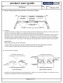
product user guide
Title
Issue
Shaftbrace
1
Date
February 2013
Contents
Page 1
Page 2 - 4
Page 5
Page 6
Page 7 - 8
Page 9
Page 10
Page 11
Page 12
Appendix A
:
:
:
:
:
:
:
:
:
:
Introduction, Design, Frame Dimensions, Hydraulic Adjustments
General Guidance Notes
Identification of Components
Typical Waling Assembly and Site Connection Details
Typical Sequence of Sheet and Frame Installation
Removal of Frames, Use of Restraint Chains (SHBP-189) Capacity 2.0T
Frame Dimensions and Leg Weights
Mechanical Pump Details and Procedures for Extending / Retracting Walings
Do’s and Don’ts, General
Provision of a Mabey Hire Site Demonstrator
1. Introduction
Mabey Hire’s Shaftbrace system is intended to be used as a temporary waling system to sheeted excavations. It is not
intended for other purposes.
The product is frequently used in combination with:
• Super Shaftbrace waling system.
• Hydraulic bracing strut.
• Mechanical bracing strut.
• Double Acting Manhole Brace.
For details of these waling systems and bracing struts within Mabey Hire’s range, refer to the appropriate set of user
information.
This booklet provides basic information for users of Shaftbrace to assist them in their preparation of a safe system of
work on site. Shaftbrace should NOT be used in seawater applications without prior consultation with Mabey Hire.
Refer to Appendix A for details of our site demonstrator service.
2. Design
No information on design is included in this booklet. Clients are strongly advised to ensure that a competent engineer is
employed to provide a suitable design for excavation schemes requiring the use of Shaftbrace products.
Mabey Hire Ltd offer a design service and can, on request, also provide information on the strength capacities of Shaftbrace products for clients undertaking their own designs.
3. Frame Dimensions
This booklet gives information for frame dimensions for Shaftbrace Walings. When Shaftbrace is used in combination
with Super Shaftbrace or Double Acting Manhole Brace consult Mabey Hire staff for frame dimensions.
4. Hydraulic Adjustments
The Shaftbrace system incorporates a hydraulic system of adjustment which is designed to extend or retract the frames
under conditions of no or low loading: e.g. as when first installed or as they become redundant after backfilling the excavation.
Once they are sustaining significant ground loads, hydraulic extension or retraction of the frames is inadvisable and is
unlikely to be possible. Methods of working should therefore avoid the need for frame adjustment / removal whilst the
walings are heavily loaded.
Page 1 of 12
product user guide
Title
Issue
Shaftbrace
1
Date
February 2013
5. General Guidance Notes
5.1 Safe System of Work and Method Statement
Assuming that the location, plan size and depth of an excavation, together with an arrangement of sheets and frames
has already been determined, the Health and Safety at Work Act requires that a safe system of work is adopted to carry
out the work on site.
These guidance notes are intended to draw the client's attention to practical aspects of Shaftbrace installation which
need to be considered in compiling method statements for a safe system of work.
In particular, the client's attention is drawn to the lengths and weights of the frame members and the need for planning
the lifting operations involved.
All major components of the Shaftbrace system are fitted with lifting lugs for safe slinging.
Two methods of constructing a typical excavation using Shaftbrace are given on Pages 7 - 8.
5.2 Manpower
The Health and Safety legislation requires that personnel deployed are suitably trained, experienced and supervised
by a competent person. All lifting operations are to be controlled by an appointed person in accordance with BS7121
and LOLER regulations.
The main activities associated with Shaftbrace installation are:
• Unloading the delivery vehicle.
• Bolting up and pinning steelwork together to form walings of the required length.
• Slinging and lifting walings into position in the excavation, and connecting the corners to form frames.
• Connecting the pump to each waling in turn, pressurizing the frames and fitting restraint chains.
5.3 Plant and Lifting
A suitable appliance is required for off-loading and installation. For off-loading there needs to be sufficient clearance
under the main hook to allow lifting with a safe angle between the lifting slings.
If the walings are to be lifted into the excavation then the appliance should be located a safe distance from the edge
of the excavation and the lifts and radii checked against the safe lifting capacities of the appliance.
In this booklet it is assumed that the frames will be lifted into the excavation one leg at a time and assembled in the excavation. Likewise for removal it is assumed that the frame will be dismantled in the excavation and the legs removed one
at a time.
WARNING : If an excavator is being used for lifting operations, refer to safety information on page 4.
5.4 Small Plant, Tools and Lifting Chains for Handling
Essential equipment required is:
5.4.1 A compressor with 100 p.s.i. output and sufficient length of air line to power the pump. The pump is fitted with a
standard 1/2" BSP air hose claw connector.
5.4.2 Sledgehammers for making pinned connections. (Not in Mabey Hire Supply).
5.4.3 Podgers/spanners for making bolted connections. (Bolt sizes are M20 for walings and M16 for struts). These are
normally supplied with Mabey Hire's installation kit.
5.4.4 Lifting chains of suitable length and capacity and with current certification. The walings have lifting lugs designed
to take 10mm safety hooks.
5.4.5 In most cases the centre of gravity of the lifts involved will not be at mid-length so shortening clutches are
advisable. Mabey Hire offer sets of 4 leg chains with 4.0m leg length c/w shortening clutches and safety hooks
(Code : SB-LSLG/SH, weight 47kg, SWL 9.0 tons @ 90O) though clients should check that the leg length is
suitable to use with their lifting appliance.
5.5 Edge Protection, Access and Hard Standing Areas
These include:• Suitable area to off-load the lorry and assemble the walings.
• Suitable hard standings for the lifting appliance to operate from if it is intended to lift the walings into the excavation.
• Ladders and possibly other provisions to provide safe access into the excavation to install restraint chains and
connect pump hoses.
• Edge protection, ladders and possibly other provisions to provide safe access into and out of the excavation. (Edge
protection and ladder access platforms can be supplied by Mabey Hire Ltd).
Page 2 of 12
product user guide
Title
Issue
Shaftbrace
1
Date
February 2013
5.6 During Excavation Works on Site
If Mabey Hire Ltd have designed the sheeting and frame arrangement for the excavation they will have used ground data
provided by the client.
If during the excavation it is noted that the actual ground conditions and / or ground water levels differ from those provided
at design stage it is advisable to have the scheme rechecked.
5.7 After Excavation Works are Completed
Plan for edge protection to be installed as early as possible.
Regularly inspect the excavation for signs of excessive movements of sheets or walings.
Check the hydraulic walings for signs of fluid leakage.
Keep plant, spoil heaps and stored materials well clear from the edge of the excavation.
5.8 Return of Equipment off Hire
Clients should ensure that on removal, the equipment is returned clean in lengths as supplied.
5.9 Transportation
Ensure all equipment is loaded to the satisfaction of the lorry driver and is securely chained / strapped to the lorry.
5.10 References
5.10.1 Legislation
The Health & Safety at Work Act 1974
The Management of Health and Safety at Work Regs (M.H.S.W.) 1999
The Construction (Design and Management ) Regulations 2007
The Control of Substances Hazardous to Health (COSHH) Regulations 1994
The Lifting Operations and Lifting Equipment Regulations (LOLER) 1998
The Provision and Use of Work Equipment Regulations (PUWER) 1998
Work at Height Regulations 2005
Noise
Manual Handling
5.10.2 HSE Guidance
Health and Safety in Construction (HSG150 - rev)
A Guide to Managing Health and Safety in Construction (ISBN 0 7176 0755 0)
Health and Safety in Excavations - Be Safe and Shore (HSG185)
Safe Work in Confined Spaces - Regulations, Approved Code of Practice and Guidance (L101)
Five Steps to Risk Assessment (INDG 163)
Excavators Used as Cranes - Guidance Note PM42
5.10.3 Other Guidance
CPA Guidance
Safety in Shoring - The Proprietary Shoring and Piling Equipment Manual
CPA (STIG) Guidance
STIG 0201 : Selection of Proprietary Shoring Equipment
CPA (STIG) Guidance
TIN 203 : The Use of Restraining Chains to Support Shoring Equipment
CPA (STIG) Guidance
TIN 204 : The Correct Use of Lifting and Other Attachment Points for Shoring Equipment
CPA Safety Guidance
Risk Assessment (SG 003)
CPA Guide Ref No. SG001(3)
Guidance on Lifting Operations in Construction When Using Excavators
CIRIA Report R166
CDM Regulations - Work Sector Guidance for Designers
Trenching Practice
CIRIA Report 97
Crane Stability on Site
CIRIA Special Publication 131
The Design and Construction of Sheet-Piled Cofferdams
CIRIA Special Publication 95
5.10.4 British and European Standards
BS 6031 : 2009 Code of Practice for Earthworks
BS EN 996 : 1996 Piling Equipment. Safety Requirements
BS EN 1997-1 : 2004 Code of Practice for Foundations
BS 5228-1 : 2009 Code of Practice for Noise and Vibration Control on Construction and Open Sites : Noise
BS 5228-2 : 2009 Code of Practice for Noise and Vibration Control on Construction and Open Sites : Vibration
Page 3 of 12
product user guide
Title
Issue
Shaftbrace
1
Date
February 2013
6. Sling Warning
Code : SSBA-007
Refer to product
user guide for
further details.
Page 4 of 12
product user guide
Title
Date
Issue
Shaftbrace
1
February 2013
7. Identification of Components
Ram Unit
Male
Male
Female
Male
Intermediate Extension (203 x 203 U.C.) Female
‘L’
‘L’
Pin to Pin ’L’ mm
Code
Min
Max Weight (Kg)
SHBP-110 1455
2055
270
SHBP-100 1855
2855
355
Code
Pin to Pin ’L’ mm Weight (Kg)
SHBP-170
500
60
SHBP-157
750
68
SHBP-158
1000
79
SHBP-154
1500
115
SHBP-155
2000
145
SHBP-188
2500
173
SHBP-156
3000
200
SHBP-161
4500
270
SHBP-177
5000
295
SHBP-162
7000
420
End Extension (203 x 203 U.C.)
Female
‘L’
Code
Pin to Pin ’L’ mm Weight (Kg)
SHBP-193
550
81
SHBP-150
1000
102
SHBP-151
1500
128
SHBP-174
2000
156
SHBP-152
2500
183
SHBP-153
3500
238
135 Degree Corner Unit
Male
Male End Extension (203 x 203 U.C.)
Male
Female
Female
135
o
Code
Dimension ‘L’ mm Weight (Kg)
SHBP-201
790
111
‘L’
Code
SHBP-195
‘L’
‘L’
Pin to Pin ‘L’mm Weight (Kg)
450
50
Male
Heavy Duty Intermediate
Extension (254 x 254 U.C.)
Female
‘L’
Code
Pin to Pin ’L’ mm Weight (Kg)
SHBP-187
500
88
SHBP-182
750
115
SHBP-171
1000
140
SHBP-168
1500
195
SHBP-172
2000
240
SHBP-169
3000
350
SHBP-186
4000
470
Code
Pin to Pin ’L’ mm Weight (Kg)
SHBP-178
5000
570
SHBP-192
7250
807
SHBP-183
8700
965
SHBP-167
9000
975
SHBP-184
10200
1125
SHBP-163
10500
1150
SHBP-166
12000
1460
7.1 Accessories
• Installation Kit : Double Acting Pump, Code : MHB-100 or PSP-101, Weight : 18 Kg empty, 43 Kg full. Hose Extensions,
Code : PSP-275. Lock-off valve spanner.
• Lifting Chain, Code : SB-LSLG/SH, Weight : 47 Kg, 10mm 4 leg chain sling, 4m E.L.L. c/w 4 No. Safety Hooks and 4 No.
shortening Clutches. Refer to Lifting Chain User Information for further details.
• Restraint Chain (Code SHBP-189), Weight 5.8Kg. 2m E.L.L. Capacity 3200Kg.
Note: When used in combination with Mabey Hire M11 sheets capacity reduces to 1500Kg. (See also Page 9).
Page 5 of 12
product user guide
Title
Issue
Shaftbrace
1
Date
February 2012
8. Typical Waling Assembly and Site Connection Details
100
Ram section
2 Sizes
(See page 5)
Box Section
Intermediate
Extension
Various lengths
(See Page 5)
203 x 203 UC
End Extension
100
Various lengths
(See page 5)
2 No. 20mm O bolts
x75mm long.
1 No. Bailey pin (48mm O) c/w spring retention clip
8.1 Assembly
The legs of the brace are made to the correct length range where possible prior to delivery, so that only the corners
need be connected using a Bailey pin complete with spring retention clip as supplied.
The lug is a close fit in the clevis, so that the legs should be as level as possible during assembly to make it easier to
assemble the joint. It is worth spending some time on levelling the ground on which the frame is to be assembled.
If the legs have to be altered to another range on site, i.e. by adding or removing an extension section, the intermediate
connection detail is used. This consists of 1 No. Bailey pin and spring retention clip and two M20 x 75mm long bolts.
IMPORTANT !
Before lifting each leg into the excavation:
1. Ensure that 1 No. Bailey pin and 2 No. M20 bolts are fitted at each intermediate connection.
2. Ensure that the spring clips are fitted and that the bolts are fully tightened.
8.2 Site Connections for Waling
1 No. Bailey Pin (48mm O)
1 No. Bailey Pin (48mm O)
2 No. M20
Bolts x 75mm
Long
Ram
Unit
End
Extension
Intermediate
or End
Extension
Intermediate
Extension
1 No. Spring Retention Clip
1 No. Spring Retention Clip
Corner Connection
Intermediate Connection
Extensions are normally attached where possible prior to delivery, but to suit site conditions, the extensions can be
changed by unbolting the 2 bolts and removing the Bailey pin.
Page 6 of 12
product user guide
Title
Issue
Shaftbrace
1
Date
February 2013
9. Typical Sequence of Sheet and Frame Installation
9.1 Method 1 : Installation of 2 frames by excavator, without piling hammer, placing one leg at a time.
WARNING : Refer to safety information on page 4 regarding excavators being used for lifting operations.
1. Fully excavate to first frame level.
1b. Alternatively excavate slit trench only to first frame level.
2. Place each leg in excavation and assemble the frame.
Connect hydraulics and pump frame out to correct dimension.
Remove hydraulics.
3
Using the frame and excavated face as a guide, place sheets
and using the relevant drive cap drive with excavator bucket
as far as possible.
4. Connect restraint chains as per scheme drawing.
5. Connect hydraulics and individually pressurise all frame ram
units to 2500 p.s.i., close lock-off valves and remove hydraulics.
6. Dig through to next frame position and push sheets down.
7. Reposition restraint chains as necessary.
8. Place legs of second frame in excavation and assemble
(safe working must be maintained).
9. Attach restraint chains between second frame and the top of the
sheets / piling.
10. Connect hydraulics and individually pressurise all lower frame
ram units to 2500 p.s.i., close lock-off valves and remove
hydraulics.
11. Push sheets down to give “toe-in” required and complete dig.
NOTE : 1. This method requires operatives working in the excavation and the
contractor must ensure safe working conditions at all times.
2. See Page 9 for notes on use of restraint chains.
Page 7 of 12
product user guide
Title
Issue
Shaftbrace
1
Date
February 2013
9.2 Method 2 : Installation of 2 frames by crane and excavator, fully driving sheets / piling with piling hammer.
Use the crane for lifting and driving operations and the excavator for digging operations.
1. Fully drive sheets/piling using a piling hammer.
2. Remove piling guide and excavate to first frame level.
3. Weld angle brackets to the piling if required to support
the frame.
4. Place each leg in excavation and assemble the frame.
5. Connect restraint chains.
6. Connect hydraulics and individually pressurise all ram
units to 2500 p.s.i., close lock-off valve and remove
hydraulics.
7. Dig through to next frame position.
8. Weld angle brackets to the piling if required to support
the frame.
9. Place legs of second frame in excavation and
assemble (safe working must be maintained).
10. Attach restraint chains between second frame and the
top of the sheets/piling.
11. Connect hydraulics and individually pressurise all
lower ram units to 2500 p.s.i., close lock-off valve and
remove hydraulics.
12. Complete dig.
NOTE : 1. This method requires operatives working in the excavation and the contractor must ensure safe working
conditions at all times.
2. See Page 9 for notes on use of restraint chains.
Page 8 of 12
product user guide
Title
Issue
Shaftbrace
1
Date
February 2013
10. Removal of Frames
Backfill to the underside of the lowest frame and carry out any compaction required. Ensure frame is securely packed
or supported from below. Connect hydraulics and individually open lock-off valves (max 2 turns) and fully retract all
lower frame ram units. Remove restraint chains. Remove corner pins, attach lifting sling to lifting eyes and lift each leg
one at a time from excavation. Follow the above procedure for the upper frame.
When the frames have been removed and the excavation backfilled, the sheets can be removed, one at a time using
a trench sheet extractor.
11. Use of Restraint Chains (SHBP-189) Capacity 2.0T *
Restraint chains are provided as a back-up support arrangement in the unlikely event of hydraulic failure of one of the
Shaftbrace hydraulic legs. They are NOT to be used for any other purpose and particularly, are NOT to be used as
lifting chains. They are NOT intended as a means of suspension to be relied upon during installation or removal of the
frames.
Always ensure all the restraint chains are fitted as per arrangement shown on the scheme drawing, or if no scheme
has been prepared 1 No. chain every 2.5 m approx of waling. Remove as much slack as possible from the chain by
repositioning the lower ‘D’ shackle.
Users must ensure that frames are securely supported by means other than the restraint chains prior to depressurizing the frames.
Forged hook for hanging over top of sheets
Chain
‘D’ Shackle
‘D’ Shackle
* NOTE :
When used with Mabey Hire M11 sheets Restraint Chain capacity reduces to 1.5T. When used with
M6 / M7 sheets capacity reduces to 1000 Kg.
Page 9 of 12
product user guide
Title
Issue
Shaftbrace
1
Date
February 2012
12. Frame Dimensions and Leg Weights
Clear Internal Sheet to Sheet Approx. Max
Leg
Dimensions
Deflection
Dimensions
(mm)
per Waling Weight
(mm)
(kg)
Min. Max.
(mm)
Min. Max.
Leg Code
Leg Arrangement
SHBL-00
SHBP-100 + SHBP-162
8705 9705
9205 10205
333
775
SHBL-01
SHBP-100 + SHBP-156 + SHBP-153
8105 9105
8605
9605
314
792
SHBL-02
SHBP-100 + SHBP-154 + SHBP-155 + SHBP-152
7605 8605
8105
9105
297
798
SHBL-03
SHBP-100 + SHBP-155 + SHBP-153
7105 8105
7605
8605
280
737
SHBL-04
SHBP-100 + SHBP-154 + SHBP-153
6605 7605
7105
8105
264
707
SHBL-05
SHBP-100 + SHBP-156 + SHBP-151
6105 7105
6605
7605
247
683
SHBL-06
SHBP-100 + SHBP-154 + SHBP-152
5605 6605
6105
7105
230
653
SHBL-07
SHBP-100 + SHBP-153
5105 6105
5605
6605
214
592
SHBL-08
SHBP-100 + SHBP-154 + SHBP-151
4605 5605
5105
6105
197
599
SHBL-09
SHBP-100 + SHBP-152
4105 5105
4605
5605
180
538
SHBL-09A* SHBP-100 + SHBP-155
3605 4605
4105
5105
164
500
SHBL-10
SHBP-100 + SHBP-151
3105 4105
3605
4605
147
483
SHBL-11
SHBP-100 + SHBP-150
2605 3605
3105
4105
130
455
SHBL-11A* SHBP-100 + SHBP-157
2455 3455
2955
3955
125
423
SHBL-11B* SHBP-100 + SHBP-170
2205 3205
2705
3705
117
411
SHBL-12*
SHBP-100 (1m stroke = 1.855m to 2.855m)
1705 2705
2205
3205
100
355
SHBL-13*
SHBP-110 (0.6m stroke = 1.455m to 2.055m)
1305 1905
1805
2405
74
270
NOTES:
* These legs only use intermediate extensions.
• If intermediate extensions are used in place of end extensions add :100mm to Clear Inside dimension.
100mm to Face of Sheet dimension.
• All legs use the SHBP-100 Ram Unit except SHBL-13
• Leg lengths over 7.0m may require bracing struts.
• Frame sizes for other combinations can be supplied by Mabey Hire Limited on request.
• The clear internal dimensions tabulated do not include any allowance for deflection of the walings
under load.
• These waling deflections are listed separately above and generally it will be necessary to increase
the clear internal dimensions by twice the appropriate waling deflection.
Page 10 of 12
product user guide
Title
Issue
Shaftbrace
1
Date
February 2013
13. Mechanical Pump Details and Procedures for Extending / Retracting Walings
13.1 Introduction
It is advisable before commencing installation to read the notes below to become familiar with the procedures involved.
The diagram below shows the pump control lever, gauge, hose connections and safety lock-off valve referred to in the
procedures.
Pump lever
set to retract
Pump lever
set to neutral
Retract
Extend
EXTEND
RETRACT
EXTEND
EXTEND
RETRACT
Pump Control
Lever (See
detail to left)
Gauge
Pump lever
set to extend
EXTEND
Safety
Lock-Off
Valve
RETRACT
RETRACT
Handle
PSP-101 Pump
Female Connector
(Retract)
Shaftbrace
Ram Unit
Male Connector
(Extend)
13.2 Preliminaries
• Check there is sufficient of the correct Mabey Hire shoring fluid in the tank. Only Mabey shoring fluid should be used.
• Set the pump control lever to "Neutral".
• Purge the hoses of air. To do this, connect the hoses together and pump for several strokes with the pump control
lever set to "Extend". When satisfied that any air has been expelled, set the pump control valve to "Neutral".
13.3 Mabey Hire Shoring Fluid
The pump is normally supplied with a full tank of pre-mixed fluid. If the fluid is separately
supplied "neat" in 5 litre orange coloured containers, it should be poured into the pump
and cold clean water added according to prevailing temperature conditions. (See table
right). Protective gloves should always be worn when handling shoring fluid.
NOTE : A Shoring Fluid safety data sheet is available from Mabey Hire Limited.
Temp Range Shoring Fluid Water
(C)
(litres)
(litres)
Above 0
5
20
-6 to 0
10
20
-10 to -7
15
15
-10 and below
Neat fluid only
13.4 Procedure for extending walings to predetermined lengths - or pressurizing a frame.
• Ensure each waling is set up level and safely on packs just clear of the ground so that it will be free to extend.
• Connect both hoses as per the diagram.
• Set the pump control lever to ‘Extend’.
• Ensure that safety lock-off valve on the ram is open by turning anti-clockwise no more than 2 turns.
• Pump to required size. If the ram does not move, refer to fault finding (section 13.6). If necessary the frame can also be
pressurized by continuing to pump. The pump will develop a pressure of 2500 p.s.i. before cutting out, corresponding
to a load of about 6 tons.
• Close safety lock-off valve with tool provided - hand pressure is sufficient.
• Move pump control lever between extend and retract a few times. This relieves pressure on the couplers and allows
easy removal and replacement of the hoses.
• Remove hoses.
• Repeat the above steps for each waling of the frame in turn.
Page 11 of 12
product user guide
Title
Issue
Shaftbrace
1
Date
February 2013
13.5
•
•
•
•
Procedure for releasing walings and retraction
Ensure the waling is secured against dropping before setting about releasing.
Set the pump control lever to "Neutral".
Connect the pump hoses to the ram unit of the waling.
Slowly open the safety lock-off valve to release the hydraulic fluid pressure and allow fluid to flow back through the
pump.
• To release frames, it will be necessary to retract the walings in turn by setting the pump control valve to "Retract"
and operating the pump until the ram is fully retracted.
• On completion of retraction set the pump control valve to "Neutral".
• Close lock-off valve in ram unit and disconnect pump hoses from the ram.
13.6 Fault Finding
In the event of the frames not extending or retracting when pumped, check the following points:
• Pump is adequately filled with fluid.
• Pump Control Lever is in the correct position for required operation.
• Both hoses are connected - double check connections to the couplers on the ram.
• Safety lock-off valve is open (rotated anti-clockwise - max. 2 turns).
• Frame is not heavily loaded.
If the ram still does not move, there may be air in the system which may be indicated by the ram springing back, and
this must be purged as follows:
• To purge pump - disconnect hoses from ram and connect hose ends together. Pump for several strokes until fluid can
be heard returning to the tank. Repeat with lever in opposite position.
• To purge ram - connect hoses, and pump ram to full extension. Reverse lever and pump until fully closed. Repeat until
there is no sign of ram springing back. If the ram still does not function properly refer to your nearest depot.
14. Do’s and Don’ts
DO install the legs of each frame one at a time.
DO install frames as level as possible.
DO use restraint chains between each frame to the top of the sheets.
DO ensure the lock-off valves are open prior to pumping.
DO ensure that the pressure is being held on the rams before closing the lock-off valves.
DO release the pump pressure after closing the lock-off valves to ease removal of hoses.
DO keep the couplers of the hoses dirt free by clipping male and female ends together after use.
DO NOT attempt to install or remove by lifting complete frames.
DO NOT over pressurise the system as this can damage the rails.
DO NOT pressurise a frame with a large gap between the rails and the sheets. A packer must be inserted to fill the
gap first.
DO NOT attempt to disconnect a hose until the lock-off valve has been fully closed, and pressure has been released
at the pump.
DO NOT release ram pressure by depressing or striking the coupler nipple.
DO NOT use restraint chains as a means of suspension during installation or removal of the frames.
15. General
Since our policy is one of continual improvement, components may vary in detail from the descriptions given in this
publication.
Page 12 of 12