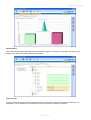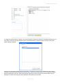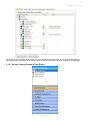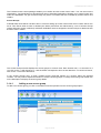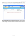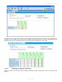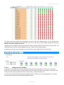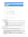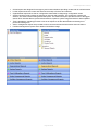
1
FUSION Operators Manual
FUSION
Operator’s Guide
Version 1.1
Tel: +44 (0) 118 979 1137 UK Tel: +44 (0) 845 155 9623 Fax: +44 (0) 118 977 3526 Email: [email protected]
Borer Data Systems Ltd, Crown House, Toutley Road, Wokingham, Berkshire, RG41 1QN
Web: www.borer.co.uk Registered in England No. 1207085
Page 1 of 84
FUSION Operators Manual
Table of Content
1.1
Introduction..................................................................................................................................................5
1.2
About this Manual........................................................................................................................................6
1.3
System Requirements .................................................................................................................................6
2.1
Starting FUSION..........................................................................................................................................7
2.2
Logging into FUSION ..................................................................................................................................7
2.3
Status Bar....................................................................................................................................................8
2.3.1
Alarm Management ...................................................................................................................................11
2.3.2
Side Tab Tab .............................................................................................................................................13
3.0
Navigating the Icon Menu..........................................................................................................................15
3.1
Organisation Menu ....................................................................................................................................15
3.1.1
Departments ..............................................................................................................................................17
3.1.3
Personnel ..................................................................................................................................................18
3.1.3.1
Access Control TAB ..................................................................................................................................21
3.1.3.2
Card & Badge Printing TAB.......................................................................................................................22
3.1.3.3
Historical Summary TAB ...........................................................................................................................23
3.1.3.4
Additional Information TAB........................................................................................................................23
3.1.3.5
Adding images to the person’s record.......................................................................................................24
3.1.3.6
Adding roles to the person’s record...........................................................................................................27
3.1.3.7
Replacing a lost card.................................................................................................................................27
3.1.3.8
Relocating a person ..................................................................................................................................28
3.1.3.9
Assigning an access profile to a person....................................................................................................29
3.1.4
Access Control Groups & Time Zones ......................................................................................................31
3.1.4.1
Adding a new access group ......................................................................................................................32
3.1.4.2
Updating a locations Time Zones..............................................................................................................34
3.1.4.3
Adding Access Profiles..............................................................................................................................35
3.1.4.4
Adding Access Roles ................................................................................................................................37
3.2
System Menu.............................................................................................................................................37
3.2.1.1
FUSION Clients .........................................................................................................................................38
3.2.1.2
Deleted Images Bin ...................................................................................................................................41
3.2.1.3
Operator Accounts ....................................................................................................................................42
3.2.1.5
Personnel Record Fields - Additional ........................................................................................................44
3.2.1.6
License Management ................................................................................................................................45
3.2.1.7
SLIO Script Templates ..............................................................................................................................45
3.2.1.8
System Settings.........................................................................................................................................45
3.2.2
System Devices & Readers.......................................................................................................................47
3.2.2.1
All Devices & Readers – General..............................................................................................................48
3.2.2.2
All Devices & Readers – SLIOs.................................................................................................................53
3.2.2.3
All Devices & Readers – MSB...................................................................................................................53
3.2.2.4
Digital Inputs..............................................................................................................................................53
3.2.2.5
IP Cameras................................................................................................................................................53
Page 2 of 84
FUSION Operators Manual
3.2.2.6
Reader Rules.............................................................................................................................................54
3.2.2.7
NIM Locations............................................................................................................................................54
3.2.3
Access Control Components.....................................................................................................................55
3.2.3.1
Alarm Definitions .......................................................................................................................................55
3.2.3.2
Area Definitions .........................................................................................................................................57
3.2.3.3
Guard Tour Routes....................................................................................................................................57
3.2.3.5
IP Camera Actions.....................................................................................................................................57
3.2.3.6
Locker Configuration .................................................................................................................................57
3.2.3.7
Muster Points.............................................................................................................................................57
3.2.3.8
Lost Card List ............................................................................................................................................57
3.3
Reports Menu ............................................................................................................................................57
3.3.1.1
Live Roll Call..............................................................................................................................................59
3.3.1.2
Muster Report............................................................................................................................................60
3.3.1.3
Roll Call Report .........................................................................................................................................60
3.3.1.4
Missing Persons Report ............................................................................................................................61
3.3.1.5
Long Term Presence .................................................................................................................................61
3.3.1.6
Long Term Absence ..................................................................................................................................61
3.3.1.7
Historical Roll Call .....................................................................................................................................61
3.3.4.1
Remote Events Report ..............................................................................................................................62
3.3.4.2
System Events Report...............................................................................................................................66
3.3.5
System Reports .........................................................................................................................................67
3.3.6
Time & Attendance Reports ......................................................................................................................67
3.3.5
Visitor Manager Reports............................................................................................................................67
3.3.5
Facilities Management Reports.................................................................................................................67
3.4
Tools Menu................................................................................................................................................67
3.4.1
Relocate Personnel ...................................................................................................................................67
3.4.2
Terminate Muster & Emergencies.............................................................................................................69
3.4.3
Backup Database ......................................................................................................................................69
3.4.4
Export and Import Data .............................................................................................................................69
3.4.5
Check Database Integrity ..........................................................................................................................69
3.4.6
Database Curbing .....................................................................................................................................69
4.0
How to Guides – General Operators .........................................................................................................69
4.1
How to add a new personnel record..........................................................................................................69
4.2
How to create an access group.................................................................................................................69
4.3
How to add more operators.......................................................................................................................69
4.4
How to perform a roll call/muster operation ..............................................................................................69
4.5
How to block a persons access.................................................................................................................69
4.6
How to report on a persons activity ...........................................................................................................69
4.7
How to setup time & attendance rules ......................................................................................................69
4.8
How to design and print a photo ID ...........................................................................................................69
4.9
How to acknowledge alarms .....................................................................................................................75
5.0
How to Guides – System Engineers..........................................................................................................75
Page 3 of 84
FUSION Operators Manual
5.1
How to maintain the database...................................................................................................................75
5.2
How to add a new location (NIM) ..............................................................................................................75
5.3
How to configure web services..................................................................................................................75
5.4
How to add new FUSION clients...............................................................................................................75
5.5
How to report on system reports ...............................................................................................................75
5.5.1
How to setup access control on a door .....................................................................................................75
6.0
NIM and SLIO Scripting Guide ..................................................................................................................75
6.1
SLIO Scripting ...........................................................................................................................................75
6.1.2
Using the Script Editor...............................................................................................................................76
7.0
Appendix....................................................................................................................................................80
7.1
Glossary of Terms .....................................................................................................................................80
7.2
Manual Revision History............................................................................................................................82
7.3
Card Transaction Error or Alarm Messages..............................................................................................82
7.4
Card Reader Related Alarms ....................................................................................................................83
Page 4 of 84
FUSION Operators Manual
1.1
Introduction
The FUSION system is a PC-based system that communicates with one or more card readers and/or alarm
monitoring devices. Each system user interacts with the system by holding a uniquely encoded identity card near
to one of the card readers to announce his/her presence. In response, depending upon the type of card reader,
either a barrier will (if appropriate) be unlocked to allow the person access (Access Control reader), or the time of
day will be noted for Time and Attendance purposes (T/A reader), or the person’s locker will be unlocked (locker
control reader) or the person will be registered as being in a safe location (Muster reader).
The main functions that the FUSION system is designed to perform are:
•
•
•
•
•
•
•
Access Control
The system can be used to control where and when people can gain access to areas of a site (or multiple
sites). When a card is presented at a card reader the card identity is read. (Each user can, if required, be
forced to type in a 4 digit PIN code in addition to presenting his/her card to the card reader). The
database is checked and if the access rules that have been defined by the system operators mean that the
card is allowed access at that reader at that time then the barrier (door/turnstile etc.) will be released. The
barrier will be monitored and when operated/opened, the cardholder will be logged as having passed
through. Any problems such as not passing through or trying to enter an area not allowed will be logged on
the database and can be reviewed at a later date.
Roll Call/Muster
The system can be used to determine where people are currently located and hence, during a
fire/emergency, which people may be in danger. Muster readers can be placed at safe muster
points. When each cardholder uses his/her card at a Muster card reader, the system identifies the owner
of the card and marks him/her as being at a safe location.
Time Recording
The system can be used to produce Time and Attendance information for people who use it. When a card
is presented at a T/A card reader the card identity is read. Optionally the card holder can type in a two digit
Absence Code at the T/A card reader to tell the system that he/she is going to be away on, for instance,
holiday or a doctor’s appointment. The identity of the cardholder, together with the date and time of the
card transaction and any Absence code typed in, are written to the FUSION database. At the end of the
working day the FUSION system will use T/A rules defined by the system operators to calculate how many
hours each card holder has worked, which ones were late, who worked overtime etc.
Locker Control
The system can be used to allocate lockers to users and to monitor and control the operation of the
lockers.
Visitor Management
The system can be used to book visitors in advance and log them in when they arrive and out when they
depart.
Photo ID Card Production
The system can be used to design and print identity badges. These can be personalised with a name,
photograph etc.
Alarm Monitoring
Events such as the triggering of a fire alarm or the unauthorised use of a fire door can be monitored within
the FUSION system. If necessary the system can be set to unlock doors automatically in the event of a fire
alarm etc.
Page 5 of 84
FUSION Operators Manual
Any or all of the aforementioned functions can be enabled within the FUSION system. Note that the menus as
presented in this manual show all functions as enabled. On your system however, depending on how it has been
configured, some menu items may not be available to you.
The FUSION system software centres around a program called FUSION SERVER, which controls the
communication (via one or more reader management devices called Network Interface Modules) between the
FUSION database and the card readers and alarm monitors.
FUSION SERVER writes information from the card readers and alarm monitors (card holder transactions, card
reader status changes etc.) into the database, and sends database changes (such as newly-defined card holder
records and updated access control rules) from the database to the card readers.
The main operator interface to the FUSION system is provided by a program called FUSION. FUSION allows the
system operators to view information received from the card readers etc. and to make changes to the
database e.g. adding new cardholder records or altering Time and Attendance rules.
The system users (i.e. card holders) may, optionally, also be given access to a small subset of the information held
within the FUSION database via a web-based program called FUSIONWeb. Using FUSIONWeb, a system user
can access the FUSIONWeb web page from their PC to acquire roll call information, view Time and
Attendance information and even request changes to the Time and Attendance information.
In its simplest form the FUSION system consists of a PC containing the FUSION database and the FUSION and
FUSION SERVER programs, together with the Network Interface Module (NIM) software, connected to one or two
card readers.
At the other end of the scale an FUSION system can have a central server containing the FUSION database, the
FUSION SERVER program and hosting the FUSIONWeb web page, several networked client PCs (perhaps each
in a different town) running the FUSION program and several networked NIMs (perhaps each in a different town)
with card readers attached.
1.2
About this Manual
Copyright © Borer Data Systems Ltd. All Rights Reserved.
MIFARE® and MIFARE® DESFire® are registered trademarks of NXP B.V. and are used under license.
Borer Data Systems Ltd. makes no warranty for the use of its products and assumes no responsibility for any errors
that may appear in this document nor does it make any commitment to update the information contained herein.
Except as permitted by such licence, no part of this publication may be reproduced, stored in a retrieval system or
transmitted, in any form or by any means, electronic, mechanical, recording, or otherwise, without the prior written
permission of Borer Data Systems Ltd. Borer retains the right to make changes to these specifications at any time,
without notice.
All images, descriptive matter, specifications and advertising are for the sole purpose of giving an approximate
description of the goods and copyrighted property of Borer Data System or/and their respective owners. E & OE all
trademarks acknowledged. Windows is either a registered trademark or trademark of Microsoft Corporation in the
United States and/or other countries. Any references to company names are for demonstration purposes only and
are not intended to refer to any actual organization.
1.3
System Requirements
FUSION SE is intended to run on a standalone PC and is the entry level solution for Borer's access control
systems. The following PC specification is for FUSION SE only. It is not suitable to install the solution on a normal
office workstation that will be used to run other office admin tasks. A dedicated PC should be used which should
remain online and not have sleep or hibernation modes enabled.
•
•
•
•
•
•
•
•
Operating Systems XP, Vista, Windows 7
Minimum Available Memory XP or XP Embedded Version (1GB RAM), Vista & Windows 7 (2GB RAM)
Available Hard Disk Space 3GB
CD ROM Drive
Screen Resolution Support 1024 x 768 Minimum, Recommended 1280 x 1024 or 1440 x 900 or higher. 32
bit colour.
Audio output.
RJ45 Network Support
CPU 2.0 GHz or above
Page 6 of 84
FUSION Operators Manual
2.1
Starting FUSION
2.2
Logging into FUSION
Before you can access the system you must identify yourself by signing on. Select the “Log In” option at the top of
the main window.
The following window will be displayed to request your operator name and password:
As shipped, the only operator defined within the system is named BORER and the associated password is also
BORER. You may log on using this operator name and password (note that password input is NOT case sensitive)
when you first run up the system and then establish your own operator record for future sign-ons.
Once you have signed on the Log In option at the top of the FUSION main window is replaced by a Log Out option.
Page 7 of 84
FUSION Operators Manual
Use this option if you wish to log out.
Logging Out
To sign off, press the Log Out button.
To exit from FUSION completely click the X on the top right on the window.
2.3
Status Bar
When you first log in to FUSION or when you select the Status main icon the system status pages are displayed;
There are multiple status windows available. These can be selected by choosing from the the available tabs. By
default the GENERAL STATUS / System Events tab is visible.
General Status
This display shows live card use activity on the main panel. To the right (top) operator acknowledgable alarms are
displayed, right (middle) NIM statuses are displayed and right (bottom) device status are displayed.
The following sub tabs are available under the GENERAL STATUS tab
Page 8 of 84
FUSION Operators Manual
•
•
•
•
System Events
NIMs - Building Controllers
System Devices & Readers
MSB NIM Source
The System Events tab shows all the live events that the logged in operator can see. Newer events appear at the
bottom of the page and scroll up to the top. This page can be scrolled using the mouse wheel, arrow keys and
page keys.
Right clicking on this screen allows you to change the filters. The filters determine what can and cant be seen.
New to 3.1 is the ability to see the card holders photo ID as part of the event stream. Right click and choose SHOW
PHOTOS to see card holders. The image and font sizes can be changed here too. Again right click to open the font
or image size selector.
The NIMs - Building Controllers tab shows the status of all the building location controllers and if they are on or
offline.
The System Devices & Readers list all devices with various issues that need operator attention. This can be
issues such as Tamper or Offline.
The MSB NIM Source view is for the BORER administrator login only. When in Enterprise DUAL mode this view
shows where MSB traffic is routing - to either the primary or secondary NIM
The General Status updates the top tab bar and created orange Tabs if system issues need pushing to the
operators view. These orange tabs include NIM issues, Reader and Devices Issues, General Operator Alarms.
Dash Board
The Dash Board tab provides an interesting overview to the amount of activity both daily and weekly that is passing
through the system.
Page 9 of 84
FUSION Operators Manual
System Status
When selected the system status tab shows a hierarchical display of all devices connected to the system. This
display is provided for engineering diagnostic purposes.
Key Personnel
The Key Personnel display provides a graphical cell for each person currently at the selected location(s). It is
designed for use in receptions or in areas where a live key personnel summary is required.
Page 10 of 84
FUSION Operators Manual
To activate this feature; from the "key personnel selection" panel choose the location(s) you wish to monitor e.g. for
a reception display it would be sensible to select the building/location that reception is based in. Then select the
personnel roles you wish to monitor. Roles must be assigned to personnel prior to this dislpay being used
otherwise the filters will not be able to locate any personnel.
Finally the time range can be changed to show how far back to search for personnel with the select roles. If the
location only has IN readers and therefore does not register people out using an OUT reader select a time range
e.g. 8 hours ago. Selecting this range personnel who swiped their cards up to 8 hours ago will be included in the
display. Personnel who swiped more than 8 hours ago are treated as being now off site.
The OPEN KIOSK MODE button changes FUSIONS display mode to full screen which removes the normal
Windows components such as the START button and task bar.
2.3.1 Alarm Management
Door Reader Operator Acknowledge Alarms
When the system receives an alarm that is marked as requiring an operator acknowledgement the ALARMS VIEW
panel will appear on the main status page.
Page 11 of 84
FUSION Operators Manual
This panel can be dragged wider to see more detail about each alarm. Alarms are shown in chronological order.
These alarms require the operator to acknowledge them in order for them to be removed from this list. To open the
acknowledgement window double click on an alarm entry. The following alarms acknowledgement window will
open.
Selecting an alarm entry shows more details about the alarm. The operator can then choose to acknowledge an
individual alarm or acknowledge all currently displayed alarms from the actions panel show above.
Digital Input Operator Acknowledge Alarms
Digital alarms are triggered from remote input devices which are configured to monitor input state changes from
sensors such as vibration, breaking glass or infrared movement detectors.
Page 12 of 84
FUSION Operators Manual
These alarms can be triggered in rapid succession from the input sensors therefore to prevent many hundred of
alarm entries in this list identical alarms will cause a count on the alarm entry to increment.
Each alarm entry has a priority code and the higher priority alarms are automatically moved to the top of the list
(e.g. see red items below) to ensure priority alarms are always on screen.
This feature is currently under development.
2.3.2 Side Tab Tab
The side Tab Bar only becomes visible if you have added doors to it already or if you press the F8 key.
Pressing F8 reveals an empty Tab Bar for an operator who has not added doors. The purpose of the Tab Bar is to
keep a list of a few doors always accessible on screen no matter where you are in the Fusion system.
The doors can then be opened by clicking on them. The doors chosen are private to each operator and cannot be
shared between operators. Therefore, each operator must allocate their own list of door shortcuts.
Page 13 of 84
FUSION Operators Manual
To add a new door to the Side Tab Bar open the view GENERAL STATUS -> System Devices & Readers as
below;
Once selected (if not aleady shown on screen) press the F8 key to reveal the Side Tab bar. Then select the IN or
OUT reader that related to the door you wish to control e.g. FRONT DOOR and drag and drop that door onto the
Side Tab bar.
An icon for the new door will be drawn on the Side Tab bar.
To remote release a door on the Side Tab bar left click on the relevant door and choose the REMOTE RELEASE
DOOR menu option. If the building controller can be contacted the door will be opened for the card access period
defined in the device setup. The door will auto lock as soon as the open time out has expired. If the building
controller cannot be contacted a failure message will be displayed.
Right clicking on the Side Tab bar allows you to open the editor to remove any unwanted doors from this bar
Page 14 of 84
FUSION Operators Manual
3.0
Navigating the Icon Menu
3.1
Organisation Menu
The Organisation menu is composed of menu items that allow you to create, alter or delete records related to the
running of your organisation. For instance you can add a new cardholder to the personnel records, or amend
cardholder access to areas of your site.
Page 15 of 84
FUSION Operators Manual
Page 16 of 84
FUSION Operators Manual
3.1.1 Departments
The Departments are grouped by the type of cardholder to which they relate, these are Staff, Contractor and
Visitor. To add a new department press the Add Department button.
Staff departments generally are used to represent the divisions within the Company/Facility that uses the FUSION
system. The Contractor and Visitor departments generally are used to represent the Companies that those
personnel are employed by.
Enter a description and type for the new Department and then press save. The departments are used during report
creation to limit reports to certain personnel types that are not used to assign access. The default department icon
shows the department that new people will be automatically added to.
Page 17 of 84
FUSION Operators Manual
3.1.3 Personnel
Page 18 of 84
FUSION Operators Manual
Initially the personnel page displays a list of people sorted by contact (employee reference). You can change the
sort method either by selecting a different option from the menu on the left of the screen or by clicking the column
heading in the main window. The current sorted column is highlighted in orange as shown below.
To view an existing personnel record select the correct entry from the list of personnel and then double click to
open the personnel editor form. To add a new people to FUSION presses the Add Person button. If you have
access rights, the personnel editor will load with a new empty record and present to the following list of tabs;
General Information Tab
The general information tab of the personnel records displays basic information about a person including their
photograph.
Page 19 of 84
FUSION Operators Manual
Person Fields
•
•
•
•
•
•
•
•
•
•
•
•
The reference number is system generated and unique to each person.
The person title is their title prefix such as Mr, Mrs, Dr etc.
The person first name field is the first name of the person.
The person last name field is the person's last name or 'surname'.
The person gender field may be left as not defined or Male or Female may be selected.
The Type & Department field can be changed by pressing the [...] button located to the left of the edit text.
A list of available personnel types and departments is provided for you to select from.
The standard card number is the card number for the person and this is the field most used for holding card
number information.
The extended card numbers 1 to 4 are provided to allow multiple access control technologies to be
supported for each person. E.g. it is possible for some locations to use Proximity MIFARE® cards and
others locations, Barcodes
The home locations can be left undefined. Leaving this undefined means that the person profile is 'global'.
Pressing the [...] button provides a list of locations to choose from. When one or more locations are
assigned to a person the building manager at each of the selected locations can make local modifications
to the person’s access rights.
The data of birth field can be left empty or provides a means of recording this information.
The telephone and mobile phone numbers are used in various reports and are useful when a person has
specific roles within a building. The mobile phone number is used for SMS communications with the
person.
The vehicle registration is used for reporting purposes and can then be linked to ANPR (automatic number
plate recognition) systems.
Facial Images
Page 20 of 84
FUSION Operators Manual
•
•
•
•
FUSION can store multiple images per person and the images can be assigned an expiry date to ensure
that the image is routinely updated.
The Load Image button will allow the operator to locate an image file (JPG or BMP) from the computer’s file
system and import the image into FUSION.
The Photo capture image function will access the local computer’s camera for photo capture and provide
access to other camera resources if defined in the camera configuration. This remote camera must be
TCP/IP camera with a compatible web interface.
The Remove Image button marks an image as deleted and the image no longer appears in the personnel
record. The image is retained in the database until the operator purges these unused images.
3.1.3.1
Access Control TAB
Access Control Fields
•
•
•
•
•
•
The access start and end dates time limit the person’s active account. If the current date does not fall
between these two dates the system will not provide access to the person even if they have valid access
groups.
When the person on trace checkbox is ticked then the system performs extra on screen logging to the
operators to highlight an individual’s activity. This feature is best used for a few personnel at any time to
ensure their activity is visible above normal personnel activity.
The card use enabled check box should be ticked to allow the persons cards to function at readers. If it is
unchecked they will be rejected from all readers.
Access enabled is also normally checked. This field is provided as a means for external systems to disable
a person’s access and should generally be left checked for a person.
The disability access rights checkbox provides an indication that a person may make use of specially
situated readers and door functions not available to general personnel.
The pin code, when in user defined pin mode, can be viewed and modified here.
Access Groups and Roles
Page 21 of 84
FUSION Operators Manual
•
•
•
In this sub tab section a list of every location available to the operator is displayed. Under each visible
location all the access groups defined for the location are displayed. To assign an access group to a
person all the operator has to do is place a tick in the checkbox. Unchecking the checkbox removes
access. The operator must press the save button to make the changes permanent.
Location roles are similar to access groups in that on the locations applicable to the current operator can
be seen. A role can be simply an indicator of a person's roles either part of their normal duties or a duty
they take on under alternative circumstances. By default a role is nothing more than an acknowledgment of
a person's responsibilities at a location. However, under the NIM configuration roles at each location can
be assigned an access group association. When this is done, the roles then enhance a person's access
rights. A roles associated access group can be defined per building so it is under the control of local
building managers as well as global operators. It is not necessarily true that the local building manager can
modify the access group they assign to the roles. This provides a level of local responsibilities to building
managers with a restricted FUSION operator login.
LDAP connector provides a one to one mapping between the personnel record and a corresponding entry
in the LDAP server. This association is maintained and changes from LDAP are pulled into the FUSION
database.
3.1.3.2
•
•
•
•
Card & Badge Printing TAB
Each personnel record in FUSION (Staff, Contractor or Visitor) can have a badge template associated with
their personnel record. The template name must be selected from the list.
The checkbox batch print required, when ticked, will cause this person’s card to be reprinted when the
operator responsible for badge production next produces a print run.
The person’s badge can be immediately printed using the print card/badge now button.
The sample image shows the print template selected using the print preview mechanism. Cards may be
printed on the front and back surface or just the front surface. Badges may also be printed here, for visitors
also and paper based badges can be designed to be sent to printers with paper stationery.
Page 22 of 84
FUSION Operators Manual
3.1.3.3
Historical Summary TAB
This tab shows the person's last 100 transactions and is a simple mechanism to report on their movement. It is
useful when trying to locate a person to know their last card swipe location. The remote events report also provides
this information with many more filtering options.
3.1.3.4
Additional Information TAB
The additional information tab provides a flexible mechanism for the system operators to define and store more
information about a person. The fields shown above are example of what can be configured.
Page 23 of 84
FUSION Operators Manual
This tab provides to panels and fields that can be defined to format data. Fields can be provided with default
values, colours and numerical ranges that can be input validated. The fields are defined in the System
Configuration section under Additional Info Fields.
3.1.3.5
Adding images to the person’s record
There are two methods to add an image to the personnel record. The first is by attaching a file located on your
computer or on your network. From the personnel record press the button labelled LOAD IMAGE FILE. The file
selection dialog will then appear.
Selected the desired file and press the OPEN button or the CANCEL button to abort the operation.
When you press the OPEN button the details dialog will appear. Enter a display caption for the image and select
the image type. The valid until date can also be changed. By default 10 years are added on to the date of image
insertion after which the image is marked as out of date.
To complete the process press the ACCEPT IMAGE to store the image in the personnel record. This image is not
saved to the person's record.
Page 24 of 84
FUSION Operators Manual
The second method of adding a picture to the personnel record is to use the photo capture function. To capture an
image the computer you are using must have a suitable MCI camera. This simply means that a USB camera or
'web cam' must be attached to the machine. Alternatively a remote network camera can be used to obtain the
photo.
To begin capturing an image press the button labelled PHOTO CAPTURE IMAGE.
The CAMERA PHOTO CAPTURE drop down list shows all available cameras with any local cameras listed first
and any network cameras listed after.
Press the OPEN CAPTURE SOURCE button to open the preview window before capturing the image.
When ready press the CAPTURE IMAGE button to take 4 quick snapshots of the person. Each snapshot is taken a
second apart to allow the person to move slightly between each image.
Page 25 of 84
FUSION Operators Manual
Click on any of the 4 thumbnail snapshots to select the best image of the person.
The green crop marks can be dragged to focus on the face to remove extra background detail. Press the CROP
IMAGE TO RECTANGLE button to modify the image to the selected crop area.
When ready press the OK button to accept the image or the CANCEL button to cancel the operation.
The image will then require a title and expiry details as before.
Press the ACCEPT IMAGE button to store the photo on the personnel record.
Page 26 of 84
FUSION Operators Manual
3.1.3.6
Adding roles to the person’s record
Open a personnel record and select the ACCESS CONTROL main tab. The select the LOCATION ROLES sub tab.
The display will show a hierarchical list of all locations and a list of all available roles at each of these locations.
Please a tick in the check box next to the role description to allocate that role to the person. Press the SAVE button
to store the changes.
Roles can have access groups associated with them.
3.1.3.7
Replacing a lost card
To replace a card number in the personnel record, simply modify the relevant card number in the person record
and save the changes. This will cause the system to update all access control devices to ensure that old card
number is blocked and that new card number is activated.
Alternatively, the LOST CARD button on the personnel record can be used to first clear the card number from the
personnel record and then create a lost card history for the person. The lost card number is recorded and cannot
be re issued to another person without the operator first clearing the lost card history entry.
Page 27 of 84
FUSION Operators Manual
After pressing the LOST CARD button, FUSION will warn the operator to ensure that the operation is correct with
the following message:
Adding this card to the lost card list will block any further use of this card and remove the card from this
persons account.
Choosing YES will force this user account to save and close.
Choose the YES button to remove the card and mark it lost. The personnel editor will save the changes and close
back to the personnel view.
To view the person's card history open the personnel record and choose the HISTORICAL SUMMARY tab.
3.1.3.8
Relocating a person
An individual person can be relocated from one system area to any other area or to the 'off site' area. There are
several reason a relocation may be required, the primary one being because the person is trying to go through a
security access controlled turnstile and they are not (logically in the database) in the correct current location to
travel to the new location.
Page 28 of 84
FUSION Operators Manual
To relocate the person open the personnel record and press the RELOCATE PERSON button.
The relocation dialog box will appear.
Choose (1) the new location for the person to be located to and then (2) the area within the location and then press
the APPLY NEW SELECTION button to update the personnel record and the system controllers.
Alternatively press the MOVE TO OFF SITE button to mark the person as being no longer on site.
3.1.3.9
Assigning an access profile to a person
The operators can define many access profiles but unlike access groups a person can have only one access
profile. An access profile however, provides a basic level of access to all location in the system. A good use of an
access profile is to give all personnel a basic access level e.g. reception level access.
Page 29 of 84
FUSION Operators Manual
To assign an access profile to a person, first, open the person's record and select the ACCESS CONTROL tab. At
the bottom of this tab is a button labelled APPLY ACCESS PROFILE. Press this button and the access profile
selector dialog will appear.
Select an access profile and then press the OK button. The person's record must be saved before the profile is
activated. Once saved the access profile can been seen. Some of the access groups can no longer be changed
and are marked with a red icon. Above the access groups tree the name of the active access profile (if any) is
displayed. All other access groups remain available to the operator for allocation.
Page 30 of 84
FUSION Operators Manual
To remove an access profile press the APPLY ACCESS PROFILE button again and choose the NO PROFILE
SELECTED option and press OK to update. SAVE the personnel record to store the changes to the database.
3.1.4 Access Control Groups & Time Zones
Page 31 of 84
FUSION Operators Manual
The FUSION access control package enables you to define and list access control rules. You can then use the
Organisation - Personnel Menu to allocate these rules to individual cardholders, allowing you to specify where and
when the cardholders can gain access through any doors or turnstiles that are controlled by access control card
readers.
Access Groups
FUSION treats each NIM as a location when it comes to setting up access control rules. Each Location has its own
set of Time Zones, when access is allowed (see below) and these are referenced by a set of Access Groups
(where and when access is allowed). Individual cardholders are then assigned to Access Groups to determine their
access to each Location.
The Access Groups window displays the access groups in a branch view. Each location has a + to the left of it. If
you click on the + it will change to a – and the branch will expand to show its sub-branches. To contract a branch,
click on the – to the left of the branch.
In the Access Groups view, a newly created Access Group will appear as a branch within the selected
Location. You may need to expand the location to view the access groups. To modify the access group double click
on the description to display the access group details.
3.1.4.1
Adding a new access group
To add a new access group you click on the Add Access Group button from the Access groups option.
Page 32 of 84
FUSION Operators Manual
The new access group will open but wont show any time zone selections until the location is chosen. Choose the
location from the drop down list of available locations. Next give the access group a unique name for this location
e.g. Office Staff. Press the SAVE button and the locations time zones and readers will be loaded into the editor
area.
The time zone and reader matrix below is now displayed. The cells correspond to the crossreferences between
time zones and the door readers at the locations. Use the mouse to left click to tick or un tick a cell. A cell also
highlights in yellow when changed so that you can see your changes. When done press the SAVE button to write
the changes to the system. If this is an existing access group and it is assigned to one or more personnel their
access rights will change within a few seconds at this location.
Page 33 of 84
FUSION Operators Manual
To allocate one or more Time Zones to a card reader click the check box for time zone and reader that is
required. You can Double click on a Time Zone or reader to select the whole row or column. The grid squares will
highlight yellow if they are modified so that you can visually see what changes you have made.
3.1.4.2
Updating a locations Time Zones
When you create a new Access Group FUSION automatically creates 32 blank time zones for use within that
location.
Page 34 of 84
FUSION Operators Manual
To modify a time zone double click its description to view the Time Zone Details screen. You can change which
days the time zone will apply by left clicking the clock icon for each day, a green triangle indicates the time zone
applies a red square indicates it does not.
Changing the time it applies is done using the start and end time drop down list boxes on the left of the screen. The
image below shows a time zone that applies 24h a day 7 days a week including holidays.
If the time zone is going to be the default for the location then tick the Default Time Zone check box.
3.1.4.3
Adding Access Profiles
The operators can define many access profiles but unlike access groups a person can have only one access
profile. An access profile however, provides a basic level of access to all location in the system. A good use of an
access profile is to give all personnel a basic access level e.g. reception level access.
To create an access profile access groups are selected at each location in the access profile editor. To create a
new access profile press the ADD ACCESS PROFILE button.
Page 35 of 84
FUSION Operators Manual
In the new access profile you will first have to provide a profile name. A small area for notes is also provided. All
locations available to the operator are shown below and when expanded all available access groups are listed. The
access profile access groups can be added by ticking the appropriate access groups. Press the SAVE button when
complete.
Upon saving, unlike access groups, the access profile mechanism needs to process through all the personnel
records and push the changes to the whole system. In databases with several thousands of personnel this process
can take a few seconds.
When an access profile is assigned to a person the access groups that are controlled by the access profile cannot
be updated from the personnel access group tab. They appear as red icons and the check boxes are no longer
available.
Page 36 of 84
FUSION Operators Manual
3.1.4.4
Adding Access Roles
Location roles can be assigned to personnel within FUSION either as part of their normal duties or a duty they take
on under certain circumstances, e.g., maintenance person or First Aider.
By default, a role is an acknowledgment of a person's responsibilities at a location. However under the NIM
configuration, roles at each location can be assigned to a specific Access Group. When this is done, the role then
enhances the person's access rights on site.
A role associated Access Group can be defined per building, so is under the control of building managers as well
as FUSION global operators. It is not necessarily true that the Building Manager can modify the access group
assigned to the roles. This provides a level of local responsibility to building managers who have restricted FUSION
operator login.
Specific access roles must be first added into the FUSION system and assigned onto an Access Group relevant to
their role, before they can be assigned to a cardholder. For example, a fire marshal role can be defined and be
allocated with 24/7 Access Group rights, giving them access on location at all times.
To add or delete a role into FUSION, click on organization from the main icons, select Access Control and then
Access Roles. Click on the Add or Delete role button.
Specify a name for the role description, select an associated icon from the drop down menu and select the role
type. Click save then close to finish.
To add access rights to this role, you must open the location NIM record and assign them from there. Click on
‘System’ from the main icons and open up the NIM list. Double click on the relevant NIM and select the tab marked
Location Access Roles. Highlight the role you wish to update, select the Access Group from the drop down menu
and click update changes. To finish, click on save and close.
To add a role to a person's record, click on organisation from the main icons and select personnel.
Double click to open up a personnel record and select the Access Control tab. Then select the location roles sub
tab. The expandable display will show a hierarchical list of all locations and a list of all available roles at each of
these locations.
Add a tick in the checkbox next to the role description to allocate that role to the person.
Press the SAVE button to store the changes and click close to finish.
3.2
System Menu
The system menu is composed of menu items that allow you to to create, alter and delete records relating to the
system configuration.
This section is divided into three main sections;
•
•
•
System Devices and Readers which allows the system hardware to be configured
Access Control Components which allows the logical system to be defined
System Configuration which contains various other configuration features
Page 37 of 84
FUSION Operators Manual
3.2.1.1
FUSION Clients
All connected FUSION software clients check into the database and update their entry in the FUSION clients view.
This enabled FUSION to know which clients are online and what features are provided at each client. The FUSION
Client software will detect the machine name and domain name and apply defaults based on the configuration
details stored in the client record.
Page 38 of 84
FUSION Operators Manual
To open a client record select the entry and double click to open the edit window. The first tab is labeled
TERMINAL DETAILS and provides a view of the clients machine details such as IP address(s), Machine name,
Domain name and current operator.
The location drop down sets the location the machine is based at. This is important configuration information for the
client as it will effect some information views.
The second tab VIDEO & PHOTO CAPTURE SETTINGS shows a list of all network cameras and this configuration
setting allows the administrative operator to define which (is any) network camera can be access from this terminal.
The purpose of this restriction is to prevent operators from one location accessing network resources from another
location if this is not desirable.
Page 39 of 84
FUSION Operators Manual
The next tab TERMINAL LOGGED OUT OPTIONS configures the terminal monitoring locations. When an operator
is not logged into the FUSION client the client can still receive events and alarms and display them on the terminal
screen. Because the terminal does not have an operators permission level if can only view this information and no
actions can be taken when in logged out mode. A good use of this feature is to provide guard room staff the ability
to monitor alarms and activity but not enable them to take any action with the client.
To enable the client to monitor one or more locations tick the check box entries for the locations required.
Warning, use the following feature with caution
The Terminal Kiosk Mode tab is only available when the Administrative Operator is logged in to the FUSION client
no other operators can access this tab. The fusion Kiosk mode can be activated with the button labeled SET
FUSION AS MAIN WINDOWS SHELL. Once activated the Microsoft Windows Explorer shell will be replaced with
the FUSION client. Once changed a reboot is required to make the change take effect.
Once in Kiosk mode there will be no access to normal Windows features. The user may still have to log into
Windows as normal but they will only see the FUSION client on screen. This feature is provided for area where the
Windows terminal may be left unattended and to prevent personnel accessing other Windows features such as
networking configuration or Games.
Page 40 of 84
FUSION Operators Manual
To restore the system to the Windows Explorer shell press the RESTORE NORMAL WINDOWS EXPLORER
SHELL button and reboot the PC. The REBOOT THIS MACHINE TO UPDATE SHELL CHANGES can be used to
reboot.
Two test buttons allow you to test the Kiosk mode feature without the need to reboot. The changes these buttons
make are not permanent and the machine can be rebooted to return the machine to its normal configuration. The
two test buttons are ENTER KIOSK MODE NOW and LEAVE KIOSK MODE NOW.
3.2.1.2
Deleted Images Bin
When an image assigned to a person is 'removed' from the person record that image is only marked as being
deleted.
To fully delete the image press the FULL DELETE IMAGE button on the view menu.
Page 41 of 84
FUSION Operators Manual
3.2.1.3
Operator Accounts
The operator accounts view shows a list of all operators in the system. This view is categorised into the following
operator types;
•
•
•
General operator logins
Operator Profiles
Web Account Operator Profiles
In all FUSION systems there is one master account and by default the account login name is BORER. Care should
be taken when resetting this accounts password as it may not be possible to change it if lost. This account cannot
be restricted in any way and can view, edit and delete all information. It is not recommended that this account be
used for normal access to the data as user accounts should be created to perform normal operations.
Account Type 1 - General Operator Logins
To open an existing operator, double click on the entry or press the ADD OPERATOR button to create a new
operator.
Operator Details TAB
The Operator Details tab provides the basic details to allow the operator to log into the FUSION system. The
General section requires the following information:
Page 42 of 84
FUSION Operators Manual
•
•
•
•
•
•
Operator full name - is the person’s real name. Not used to log in but is used for reporting and display.
Operator login name - a short name that is used as the name part of the login process. It must be at least 5
characters long.
Use NT Authentication - when ticked takes the user name from the currently logged in Windows user. To
use this feature the operator login name must be set to be the same format as the user login name.
FUSION will check the currently logged in Windows user on startup and check the operator’s database to
see if there is an exact match. If the Windows PC is on a DOMAIN then the next field must be provided for
this feature to work.
Login NT DOMAIN - the exact Windows Domain name that the machine is connected to.
Operator Email - the email address used to communicate with the operator. The email is used for
automated emails.
Operator Mobile - the mobile/cell number used to communicate with the operator. The mobile is used for
automated SMS messages.
The Options section requires the following information:
•
•
•
•
Account expiry date - the date after which the operator account will no longer log into FUSION.
Account Enabled - if this is unticked then the operator cannot login.
Language Mode - (Default UK) the client software language mode.
Access Profile - if this operator uses a profile account select the operator profile otherwise leave as USE
OWN LOCATION ACCESS RIGHTS
The Operator Account Type section should be set to the default "Operator Login Account" for this account type see
below for details of the other two account types.
Global Access Rights TAB
These global access rights relate to functions and information that is not necessarily part of the standard
information views and so needs a separate permission. Ticking any of the check boxes enables the permission.
Location Access Rights TAB
Page 43 of 84
FUSION Operators Manual
The Administrative operator cannot have less than full access. All other operators have varying degrees of access
based on the Location Access Rights TAB. For all locations an operator can have VIEW, CREATE/MODIFY,
DELETE rights for several record types. In addition to this report generation can also be restricted along with
system actions such as Remote Door Release and Personnel Relocation.
To modify any element above, select the location and tick or untick the relevant entries. Any location’s settings can
be copied to all locations by pressing the COPY SELECTED SETTINGS TO ALL LOCATIONS button.
Account Type 2 - Operator Profile Account
An operator profile account can be created to allow a single set of rights to be setup. This account does not permit
login to FUSION. Instead, new operators can be created and linked to this profile. When the profile is updated the
real operator accounts linked to this profile are also updated. Using this mechanism, staff with the same general
access rights can be grouped and easily maintained.
Created the profile by changing the OPERATOR ACCOUNT TYPE to Operator Profile Account within the Operator
Details TAB section and saving the profile. Then create an operator as normal but select from the Operator Details
TAB the Access Profile value corresponding to the name of the new operator profile and save the new account.
Account Type 3 - Web Account Profile
This account type is similar to operator profiles. However, this profile applies to personnel. Personnel can be
allowed to log into various web interfaces in FUSION such as Time & Attendance, Visitor Manager and Local
Building Manager WEB FUSION. When these personnel log into a web interface their user ID and password are
required. When they access the FUSION system the Web Account Profile permissions are used to allow them
to view, create and delete data.
3.2.1.5
Personnel Record Fields - Additional
There are no Additional Personnel Record Fields defined in FUSION by default. This view allows you to define
extra fields that appear in the personnel editor. The fields can be used for any purpose required and they provide a
simple means of formatting input data to ensure the data collected is consistent.
To create a new Additional Field press the ADD FIELD button from the view button bar. The first thing to do is to
select a caption for the field. As an example enter the Field Caption called "Grade" which will represent the
employment grade of a person. You must then choose the field type of which there are several;
•
•
Text Edit - any text input. Text may be forced to upper or lower case, have a default value and be of a
maximum length.
Date Edit - a date value
Page 44 of 84
FUSION Operators Manual
•
•
•
•
•
Time Edit - a time value
Formatted Text - formatted text is similar to Text Edit except that an INPUT MASK can be supplied. The
input mask forces formatted alpha or numeric values in a defined order.
Checkbox - a simple tick box with a caption.
Pick List - a list of values any one value can be selected and the field can be displayed as a list of radio
buttons, a drop down list or a list box.
Text Box - a text entry box larger than one line like the text edit field.
Note, leaving the field Max Character Length as ZERO limits the field only to the size of the database storage unit
with is 4KB.
Mandatory input of information can be enforced by ticking the INPUT VALUE COMPLETION IS MANFATORY
check box.
Choose the Field Type as Pick List and select the RADIO BUTTON LIST from the Pick List Style. Now enter three
grades in the PICK LIST OPTIONS - ensuring that you enter each grade type on a new line in the edit window.
e.g.
BASIC
CONSULTANT
SNR CONSULTANT
Now open or create a personnel record and change to the Additional Information TAB and the new field will have
been added to the personnel record.
3.2.1.6
License Management
3.2.1.7
SLIO Script Templates
The SLIO 42 and SLIO 88 units provide a number of digital inputs and outputs. These units can be set to passively
monitor digital inputs and provide outputs. The NIM can control these devices through several means one being the
IO Matrix and the other being NIM Scripts.
The SLIOs however, can have a script downloaded to their memories. The script auto repeats and runs constantly.
The templates section provides a list of pre defined scripts that are commonly used such as air lock controller and
personnel in out counter.
You can add more templates to this library to create a new script see the NIM Locations Document below;
3.2.1.8
System Settings
There is only ever one entry in the System Settings view and it cannot be deleted. Double clicking on the single
entry opens up the system settings editor.
Page 45 of 84
FUSION Operators Manual
General Configuration TAB
•
•
•
Personnel Record - Name Format; this field changes the format of the cardholder name that is displayed in
reports and views
Database Auto Curbing
o Remote Events - max number of days to keep data for, then the system will delete back to the
delete setting
o Attendance Data - max number of days to keep data for, then the system will delete back to the
delete setting
o System Events - max number of days to keep data for, then the system will delete back to the
delete setting
o Auto Curbing allows the FUSION server to perform the curbing on a schedule
Time & Attendance - Auto Calculation Start Date: the first day the calculation will start computation from.
System Facility Codes TAB
There is one field set for each of the card entries in the personnel record. Note that only BORER access control
devices can be used for Transport Key modification and MIFARE® Data sector number.
•
•
•
•
•
Enable None Default Configuration - the system will enforce the changes you make - take care not to
change these values to incorrect settings or you will prevent access control working.
Facility Code - the site code that prevents a one card issued by BORER working at another customer with
the two cards having the same card number. BORER ensures that all customers who use their card are
supplied with different facility codes.
Read Transport Key - The MIFARE® transport key for reading card data. (BORER readers only)
Write Transport Key - The MIFARE® transport key for writing card data. (BORER readers only)
Data Sector Number - The MIFARE® sector that data is to be stored at. The BORER default is 7. (BORER
readers only)
Page 46 of 84
FUSION Operators Manual
Pin Codes & Encryption TAB
•
•
•
Pin Codes are System Generated - the FUSION client will save a pin code for each person based on their
card number. This PIN value cannot be edited.
Pin Codes are user defined - the FUSION Operator must provide a 4 digit pin code for each person. This
value can be changed as required.
NIM Link Encryption - the data channel between FUSION Server and any NIMs can be encrypted. A key
must be provided at both sides.
Email Server Link TAB
Send Email Configuration
•
•
•
•
•
SMTP Server Address - IP address or network name of the SMTP server used to send emails from
FUSION
SMTP User Name - the login name for an account allowed to send SMTP data. (Only required if SMTP
AUTH Set)
SMTP Password - the login password. (Only required if SMTP AUTH Set)
SMTP Requires Authentication - Set SMTP AUTH flag to send User Name and Password before emails
are sent.
EMAIL Address - the email address of the FUSION System that emails come FROM e.g
[email protected]
Receive Email Configuration
•
•
•
POP3 Server Address - IP address of the network name of the POP3 server used to receive email from
into FUSION.
POP3 User Name - the user name used to log into the POP3 server.
POP3 Password - the password for the login account.
LDAP Integration Config
Synchronisation with LDAP is one way only and uses an ADO data connector. The ADO Connection string must be
modified to conform to your LDAP server. The LDAP DC field must be modified to correctly filter personnel data.
The Synchronisation Rules define how personnel are synchronised with the LDAP records. The FUSION server
performs periodic synchronisation the with LDAP server.
3.2.2 System Devices & Readers
Page 47 of 84
FUSION Operators Manual
3.2.2.1
All Devices & Readers – General
This view provides a list of all devices and readers defined in the FUSION system.
Modifications to the device and reader configuration should only be performed by the engineering personnel. All
devices when first introduced to a communications channel perform an AUTO MOUNT procedure and
get automatically assigned an unique bus identity on the Midspan or IP Bridge that they are connected to.
The default settings, however only permit the device to function in a basic manner and by default implement
security locking doors etc
To manually create a new device click on the ADD DEVICE button or open an existing device definition record.
Device General Details
The first tab on the Device editor controls the device type which changes the format of the further tabs.
The available Device Types are as follows:
Page 48 of 84
FUSION Operators Manual
•
•
•
•
•
•
•
•
•
•
•
Access Control Reader - This can be either the BORER MIFARE® readers, BORER Hitag Reader or the
BORER LIM for connecting Wiegand third party reader heads. The device will function as an access
control reader and may or may not have a Lock Manger associated to it depending on the system
configuration.
Time & Attendance Reader - This can be either the BORER MIFARE® or HiTag Readers which will
generally be determined by the access control technology used at the location. This device provides a
keyboard for time and attendance data entry and has a display to show the person's information.
Muster Reader - This can be either the BORER MIFARE®, HiTag Reader or LIM but the device will not be
treated as an access control reader. Personnel will not be downloaded to this reader to prevent offline
operation.
Registration & Assembly reader - This can be either the BORER MIFARE® or HiTag Readers and is
used for gathering school attendance data by locating the reader device in classrooms.
Locker & cabinet Controller Terminal - This option is limited to the BORER MIFARE® Display terminal
reader.
Digital Input Output Device - This device type is either a SLIO 4x2 or a SLIO 8x8
Door Lock Manager - READER ASSOCIATION MODE - normal operation for a lock manager. A lock
manager must 'pair' with one or two readers to control the locking mechanism (Maglock or strike lock). The
lock manager configuration allows the device pairing to be configured.
Door Lock Manager - HOTEL, LOCKER & CABINET MODE - in this mode the lock manager still controls
a door lock but is controlled by a reader. Multiple lock managers can be daisy chained together with one or
more access control readers. When the reader accepts a card one or more of the lock managers can open
their door releases. This suits a hotel type door configuration or an IT cabinet configuration.
IP CAN Bridge - A single channel one port bridge allowing up to 60 devices to communicate on this
channel.
IP MIDSPAN Bridge - An 8 port device providing both power and data to lock managers and their
associated readers.
CAN HUB (Deleted product) - A three port data only router. Used for cable length extension.
Device Configuration Options
Area Transition Details
•
From Area - The area that the reader takes you from (when green) i.e. the area you are currently located.
Page 49 of 84
FUSION Operators Manual
•
•
•
To Area - The area the reader takes you to (when green). The card holder’s logical location is only updated
to the TO AREA when 1) a Green access is given to the card holder and 2) a door open event is detected
(access made).
Associated External Entry (IN) Reader or Security Controller - When using only BORER Readers or
LIMs to construct an In/Out door path (i.e. no lock managers used) then the reader on the 'safe side' is
responsible for the door lock. The unsafe side is only responsible for acknowledging the card. The unsafe
side reader will logically instruct the safe side reader to open the door. This is a messaging protocol, not a
simple level signalling system so cannot be 'shorted out'. A SLIO42 can also be used to control the lock
thus acting as a security controller device.
Time Embargo - see reader rules for further description - determines how long to block the card from reusing the specific access control reader. This is to prevent a person from following a certain path too soon also see anti pass back in reader rules.
Device Time Options
•
•
•
Green LED Indicator ON - Only when the reader is paired with a lock manager - this value determines the
green LED on time for the readers. The actual door open time is configured in the controlling lock manager.
Door Lock Release Time - (when no lock manger used - not shown in above image) - When the reader is
set to control the door open via this relay this time value determines how long the door opens for. If the
door is detected as being open, the relay will be cancelled and the door will relock when closed.
Door Open Alarm Shunt Time - The delay after which if the door is still open (requires door monitor) then
the local reader alarms will trigger. BORER MIFARE® & HiTag readers both contain an alarm tone. The
BORER LIM provides a secondary output relay to control an alternative alarm source / signal.
Device Feature Options
•
•
•
•
•
•
•
•
•
•
•
Use Local Decisions... - This option, when ticked, overrides the default reader card processing sequence.
After detecting a card - the BORER reader will request authentication from the NIM. If the NIM responds
within 2 seconds the transaction will continue and the card holder will get a red or green response. If,
however, the NIM response time is >2 seconds then it is assumed to be offline and a long RED will be
given to the card hold to show offline. The cardholder can then re-present their card and the reader will try
the NIM again for a decision. If this time the decision still does not come from the NIM (still offline) then the
reader will make a local decision based on its own memory. Ticking local decisions bypasses the first timed
out long red indicator and the reader always uses its local database as an alternative decision source
(when the NIM does not respond).
Enable Simple Time Recording - Allows the reader to act as a simple in out time recording terminal with
no display of keyboard input.
Enable Local Alarm - Causes the local alarm to sound when the door is held open beyond the local alarm
time out.
Enable Qualification Checking - Enables this mode - NB. Functionality is at NIM level only.
Enable Role Checking - Enables this mode - NB. Functionality is at NIM level only.
Reader Controls Turnstile - Modifies the readers operating mode to control a turnstile rather than a door.
Enable Duress Alarm - When the PIN code is entered in reverse for a PIN code reader this will cause the
operators to receive an on screen alarm that the person entering the PIN is being forced to do so.
Reader in Silent Mode - BORER MIFARE® reader - all sounds are disabled if this feature is enabled.
Reader has Pass back Switch - Informs the system not to raise a door forced if the door opens without a
card being presented.
Anti Pass Back - Enabled anti pass back to activate when the reader rules dictate.
Door Monitor Not Available - Sometimes it is not possible to fit a door monitor to a door or barrier being
controlled by a reader. When this is the case this tick box lets the system deal with this state and records
the person as being in the TO Area as soon as the Green is acknowledged rather than waiting for the
ACCESS MADE system message from the reader.
Card Number Source Options
This drop down field selects the card source. By default the standard card number is used from the personnel
record. The personnel record can store several card numbers - a feature which is very useful when supporting two
or more access control card formats during system install or integration.
In addition to the standard to extended card number ranges the standard card (only) can be set to use MIFARE®
Serial mode. This mode set the BORER MIFARE® reader to read only the MIFARE® Serial Number and not the
Page 50 of 84
FUSION Operators Manual
encrypted card number. This is useful if you are using non-BORER MIFARE® access control cards and wish to
make use of them with the FUSION system.
Door Lock Manager Configuration
When the device type is set to lock manager there is additional configuration required. The lock manager should be
associated (* except see below) with one or two readers. These readers can be selected from the drop down lists
in the Associated IN and OUT readers. Once associated the reader device records will display the name of the
device they are associated with (see second image above).
•
•
•
•
•
•
•
Pre Lock Activation Delay - A delay time in seconds that the lock manager delays powering the lock (or
removing power for Maglocks). This is provided for hotel mode use where a door may be several metres
from the reader.
Door Lock Release Time - As above. Maximum time to hold door lock disengaged. Auto cancels when door
monitor open detected.
Door Open Alarm Shunt Time - As above.
Door Monitor Not Available - As above.
Reader Controls Turnstile - As above.
Lock Manager Used as Power Convertor Only - Used to provide a 12v power source only at the end of the
line. No locking will be controlled by this device.
Lock Manager has Monitored Lock Input - TBC
Power Control Features
•
•
Fail Secure - Power is only output from the lock manager when unlocking the door.
Fail Safe - Power is constantly provided to the lock (Maglocks or Electric Strikes) when locked.
Power Levels
•
•
•
Initial Power Level - From 0 to 100% power output for an initial period. This phase of the power cycle is
used for a short period to provide the lock state change power force. This power level is normally not
necessarily maintained for the duration of powering the lock.
Initial Power Level Duration - The time to apply high power to the lock to force it to change state / obtain a
good holding force. Normally times from 1/2 second to 2 seconds are required.
Sustained Power Level - The sustained power output from 0 to 100% power to maintain the lock changed
state / holding force.
Page 51 of 84
FUSION Operators Manual
Power Level Configuration Examples
Magnetic Lock
Magnetic locks require a high power level for the first second then a moderate sustaining power level.
E.g. Initial Power 90% for 1 second, Sustained Power at 70%.
Electric Strike Lock
Strike locks require a high power level for the first second then a low sustaining power level.
E.g. Initial Power 80% for 1 second, Sustained Power at 50%.
Device Reader Rules
Page 52 of 84
FUSION Operators Manual
Every day of the week can be set to have an alternative reader rule set. The reader rule itself, has 5 time zones
and an emergency zone. Also if the current date is logged as a holiday the holiday rule can be activated. See
Reader Rules.
3.2.2.2
All Devices & Readers – SLIOs
3.2.2.3
All Devices & Readers – MSB
3.2.2.4
Digital Inputs
3.2.2.5
IP Cameras
Page 53 of 84
FUSION Operators Manual
3.2.2.6
Reader Rules
3.2.2.7
NIM Locations
Page 54 of 84
FUSION Operators Manual
3.2.3 Access Control Components
3.2.3.1
Alarm Definitions
The alarms list shows a set of predefined alarms for general system use. The existing alarms and index number
should not be changed although the descriptions can be amended as necessary. New alarms can be added at the
end of the list.
To create a new alarm press the ADD ALARM button or to open an existing alarm, double click on any entry.
Page 55 of 84
FUSION Operators Manual
Alarm Details
•
•
•
•
•
Alarm number is an unique reference number and should not be changed.
The Alarm Description can be amended as necessary
Alarm Action is displayed for the operator as instructions to take further action if necessary
Display Alarm on FUSION Screen ensure that the alarm appears on the status display
Require Operator Acknowledge This Alarm Type - Forces the alarm to enter the operator(s)
acknowledgeable display and will stay on the status screen until it is cleared.
Alarm Sounds
•
•
•
•
Silent Alarm - Makes no sound (Default)
System Beep - Uses the Windows default beep to alert the operators
Customer Sound - Choose from a large list of embedded sounds
Computer Speech - Using the Windows Speech Synthesizer Voice to speak the alarm description. If an
alternative Spoken Message is provided it will be used instead of the default alarm message text
Page 56 of 84
FUSION Operators Manual
3.2.3.2
Area Definitions
3.2.3.3
Guard Tour Routes
3.2.3.5
IP Camera Actions
3.2.3.6
Locker Configuration
3.2.3.7
Muster Points
3.2.3.8
Lost Card List
3.3
Reports Menu
Reporting Overview
The reports menu contains several report types categorised by their context.
Page 57 of 84
FUSION Operators Manual
•
•
•
•
•
•
•
Critical reports are designed for emergency and muster situations providing muster and roll call information
Locker reports show the current and historical ownership of lockers and cabinets
Organisational reports show lists of configuration data useful for diagnosing configuration issues
System reports provide a means of reporting on devices and hardware. This report item contains two
sections, the second section being advanced reports. The advanced reports provides access to all logged
events which includes alarms, personnel transactions, operator system usage and devices status updates.
Time & attendance reporting provides a rich set of reports to aid the administration and analysis of
personnel working time.
Visitor management reports are provided to show current and historical information about all visitors.
Facilities management reports show details of all facilities usage.
Page 58 of 84
FUSION Operators Manual
Common Reporting Features
When the reports are generated they offer two formats of output depending on the type of report. The basic report
provides a list of report information such as all devices or all reader rules. These basic reports can be saved or
printed in the following formats:
Save As
•
•
•
CSV - Comma Separated Value text file output which can be read by programs such as Microsoft Excel or
other database tools.
HTML - Saved as a self-contained web page that can be opened in Microsoft Explorer or alternative
browsers.
PDF - Portable Document Format file that can be viewed in the Adobe PDF viewer which is a common tool
found on most computers. This format is suitable as an email attachment.
Print
Prints to the selected printer (or for multipage reports some of) all the pages.
3.3.1.1
Live Roll Call
Page 59 of 84
FUSION Operators Manual
The Live Roll Call display differs from the static reports, in that, it automatically updates its contents every few
seconds. This report shows a personnel count for each area, at all locations. By clicking on any of the items in the
Personnel Areas List, the Personnel at Area Report will update to show an alphabetic list of personnel.
This list is also drag and drop enabled, so that by selecting a person from the right hand list they can be dragged
and dropped onto a new area. This is an alternative personnel relocation tool. In a similar, all personnel at one area
can be dragged and dropped onto another area.
3.3.1.2
Muster Report
The Muster Report indicates which Muster Point each cardholder is at and the date and time that they arrived
there. The other roll call reports indicate which Area each cardholder is in and the date and time that they arrived
there.
Muster Report – The muster report displays cardholders who are registered as being at Muster Points. Typically
this report might be used in an emergency or during a fire drill when cardholders are expected to make their way to
the Muster Point(s). The Muster Point that each cardholder is at and the date and time of his/her arrival there are
listed.
3.3.1.3
Roll Call Report
The Critical Reports view includes five options that allow you to list information relating to the current whereabouts
of cardholders (Roll Call Report, Muster Report, Missing Persons Report, Long-Term Presence Report and Long
Term Absence Report) and one option that allows you to list information relating to where cardholders were at a
given date and time in the past (Historical Roll Call Report).
Page 60 of 84
FUSION Operators Manual
Note, for roll call reporting to operate successfully, a site must have card readers that register cardholders arriving
and departing on, otherwise the system cannot know where cardholder are. Similarly the site can only be broken
up into Areas for the purpose of roll call reporting, if access in and out of each Area is controlled by a card reader.
Roll Call – The roll call report displays cardholders who are onsite (and, if the Include Offsite Area checkbox is
ticked, people who are offsite as well). The Area that each cardholder is in and the date and time of his/her last
successful card transaction is listed.
3.3.1.4
Missing Persons Report
Missing Persons – The missing person’s report lists cardholders who are recorded as being onsite, but who have
not reached a muster point. Typically this report might be used in an emergency or during a fire drill when
cardholders are expected to make their way to the Muster Point(s). The Area that each cardholder is in and the
date and time of his/her last successful card transaction is listed.
The date and time of the cardholder’s last recorded card transaction should be taken into account before sending
someone into a burning building to locate the cardholder. If the cardholder has not used a card reader today
he/she may actually not be onsite, having left site on a previous day without using a card reader.
3.3.1.5
Long Term Presence
Long-Term Presence – The long-term presence report lists cardholders who have been onsite since before a
particular date and time. A date and time selection panel replaces the Areas selection list when this option is
chosen, allowing you to specify the required date and time. The Area that each cardholder is in and the date and
time of his/her last successful card transaction are listed. This report is primarily used to identify cardholders who
are recorded as being onsite but who may not be.
For instance, a contractor might have an access control card to move about onsite, but might then leave site
without using a card reader and not return to site for weeks. The system will record him as still being onsite so
during an emergency situation, he will incorrectly show up as a missing person. However, by regularly using the
long-term presence report to list cardholders who are recorded as being onsite but have not used a card reader for
the last 24 hours, within a day the contractor would appear as a long-term attendee. The system operator could
then carry out enquiries to confirm that he is indeed offsite and then use the Relocate People Individually item in
the Action menu to move him offsite.
3.3.1.6
Long Term Absence
Long-Term Absence – The long-term absence report lists cardholders who have been offsite since before a
particular date and time. A date and time selection panel replaces the Areas selection list when this option is
chosen, allowing you to specify the required date and time. The Area that each cardholder is in and the date and
time of his/her last successful card transaction is listed. This report is primarily used to identify cardholders who
are not longer using the system.
For instance a cardholder may no longer be employed, but perhaps the operators of the FUSION system were not
told. By regularly using the long-term absence report to list cardholders who have not been onsite for perhaps the
last month the system operator can identify cardholders who should potentially have their access permissions
removed (in case someone else acquires their card and tries to access the site).
3.3.1.7
Historical Roll Call
Historical Roll Call – The historical roll call allows you to list which people were present in which Areas at a
specified point in time or at some point during a specified period of time, in the past. The Area that each
cardholder was in and the date and time of his/her last successful card transactio at the time are listed. When you
select this type of report and press the OK button you will be prompted to enter more selection criteria before the
report is produced.
You will be asked to specify whether you are interested in which cardholders were present at a particular point in
time or which cardholders were present at some point during a particular period of time. You will be prompted to
specify the date and time of the point in time or the date and time of the start and end of the time period. You will
also be prompted to indicate how far back in the remote events table you wish the program to search for relevant
data. This is because the system works out where cardholders were at a given time by monitoring their card
transactions during the hours (or days) leading up to that time.
Customers whose business closes down at night would typically specify that the system should check cardholder
transactions from the start of the day that includes the time point/period for which the report is being taken.
Page 61 of 84
FUSION Operators Manual
Customers who have staff who might be in attendance for perhaps three days at a time without leaving site, would
probably specify that the system should check cardholder transactions from four days before the day that includes
the time point/period for which the report is being taken.
3.3.4.1
Remote Events Report
The Remote Events Report allows the operator to analyse the personnel and alarm events stored in the database.
The report provides a number of TAB sheets to allow the operator to query the historical information within the
database.
General Report Options
This first tab allows the operator to set the date time start and end range. The QUICK SELECT button provides a
list of commonly used date range options:
Date Time Range
•
•
•
•
•
•
Report Today - 00:00 to current time
Report Chose Start Date - Select the whole day from 00:00 to 23:59. The start date is not
modified.
Report Yesterday - 00:00 to 23:59 for all yesterday’s events.
Report Last 7 Days - Date time range set to seven days ago and report ends at current time
today.
Report Last 14 Days - Similar to 7 day report.
From First Remote Event in Database - Check the database for the first event record and set the
start date time to that value. Note that this report can take a very long time and heavily use
Windows resources.
Event Type Options
Select the event types you wish to report on. Events are denoted with a single character identity, an explanation of
all the event type identities is as follows;
•
•
•
•
•
A - NIM authorisations - Sent after a 'Green' is send to the reader but comes before the Access
Made or Access Not Made messages from the reader. This event type identity is purely for
diagnostic purposes and is rarely used in live systems.
G - Green Access Made - After a green is sent to the door reader and the door opens the Access
Made message is returned from the NIM to the database. This is indicated by the G event type.
K - Alternative to G when pin codes are used. Denotes Access Made.
M - When a card is used at a muster reader, as long as the card is in the database, the card will
get a green. If the cardholder has no access rights, they will still get a green from a muster reader.
T - Wrong Time and Attendance Reader used. (Depreciated Message Type).
Page 62 of 84
FUSION Operators Manual
•
•
•
•
•
•
R - Red transactions have several meanings. Red card rejected or red alarm.
P - Passback switch on the safe side of the door was used and the reader noted the door open
without a card event taking place. If the passback switch flag is set on the reader record this event
type will be sent. If the flag is not set in the reader record the alarm Door Forced will be sent.
+ (PLUS SYMBOL) - Reader has an alarm message (See the alarm description on the status page
to determine which alarm).
- (MINUS SYMBOL) - Reader has cleared the previous alarm state.
S - Digital Alarm from a digital alarm input has set.
U - Digital Alarm from a digital alarm input has cleared.
By default, a suitable set of ticks are set in the Event Type Options to report on personnel activity.
Selected Personnel Filter
This next tab provides additional filtering. By default the report will extract all events for all personnel but the
filtering will reduce the size of the report by selecting only a sub set of the report. The default is no Personnel
Filters.
Selection Type
•
•
•
•
•
•
•
•
No Personnel Filters - Default Setting.
Personnel on Trace - In the personnel record the person can be put on trace by ticking the
PERSON ON TRACE tickbox in the Access Control TAB. All (or those then selected) personnel on
trace can then be reported on. Once selected the personnel with the trace flag are extracted and
displayed in the Selected Personnel ... list box. By default, all are selected the operator can choose
to deselect any or all of them to limit the report further.
Staff - All personnel are loaded into the Selected Personnel ... list who are in a contractors
department / company. You can then clear the selection and select only a few personnel.
Contractors - All personnel are loaded into the Selected Personnel ... list who are in a contractors
department / company. You can then clear the selection and select only a few personnel.
Visitors - All personnel are loaded into the Selected Personnel ... list who are in a visitors
department / company. You can then clear the selection and select only a few personnel.
From Selected Departments - The selection box changes to a list of department / company
names. You can then select one or many companies to report upon.
Selected Personnel - All personnel are loaded into the Selected Personnel .. list. You can clear or
set all the ticks and choose only a small selection of the personnel.
Selected Personnel Daily First & Last - Select personnel from the Selected Personnel ... list and
the report will show the persons first card use of the day and their last. This is a basic time and
attendance feature.
Page 63 of 84
FUSION Operators Manual
Selected Readers
A final filter allows the report to focus on a selection of reader devices only. Clicking a LOCATION caption
automatically tick/untick all readers at the location. If all readers are unticked, they can then be individually ticked to
choose one or a few readers to filter the report.
Grouping – Select whether or not you wish the report to group cardholders by Personnel Group or, where
appropriate, by Area or Muster Point.
Order By – Select whether you wish cardholders to be listed in name order or reference number order.
Select Personnel – Select a single specified cardholder be reported on, or that all cardholders who belong to one
or more specified Personnel Groups be reported on.
Page 64 of 84
FUSION Operators Manual
Select Area(s) – Select which Areas should be included in the report, including or excluding the offsite area. In the
case of a muster report this is replaced by a Muster Point selection list.
The Roll Call Report display where personnel are currently located and the date/time of their last successful card
transaction.
Page 65 of 84
FUSION Operators Manual
3.3.4.2
System Events Report
The System Events Report allows the operator to review events that have occurred in the FUSION software.
Event Date and Time Range
•
•
•
•
•
•
Report Today - 00:00 to current time
Report Chose Start Date - Select the whole day from 00:00 to 23:59. The start date is not modified.
Report Yesterday - 00:00 to 23:59 for all yesterday’s events.
Report Last 7 Days - Date time range set to seven days ago and report ends at current time today.
Report Last 14 Days - Similar to 7 day report.
From First Remote Event in Database - Check the database for the first event record and set the start
date time to that value. Note that this report can take a very long time and heavily use Windows resources.
Event Type Options
Select the event types you wish to report on.
Other Filters
The Other Filters allow the selection of operators to filter events to a particular operator account.
Page 66 of 84
FUSION Operators Manual
3.3.5 System Reports
3.3.6 Time & Attendance Reports
3.3.5 Visitor Manager Reports
3.3.5 Facilities Management Reports
3.4
Tools Menu
The Tools Menu contains a set of functions for maintaining and modifying the FUSION database. Care should be
taken when using these features and because of this access is limited to Administrative Operators.
3.4.1 Relocate Personnel
The relocate personnel - Relocate Individual TAB allows a single person to be located in the database by
searching for either their card number, their name or their reference number. A partial value may return several
personnel and the correct person can be selected from the Seach Results list box.
When the correct person is selected the list of avilable locations updates. Select a new location followed by an area
at the location to relocate the person to.
Press the RELOCATE PERSON button to update the persons logical location in the database.
Page 67 of 84
FUSION Operators Manual
Relocate en Masse - is a simple option.
When presses the RELOCATE ALL PERSONNEL OFF SITE button moves all personnel to the off site location.
This feature is used only to 'reset' the entire database personnel location management. An example of its purpose
is during or after a site evacuation personnel may have not swiped out correctly. Pressing this button will return all
personnel records to a good know state, useful when anti pass back is enforced.
Page 68 of 84
FUSION Operators Manual
3.4.2 Terminate Muster & Emergencies
3.4.3 Backup Database
3.4.4 Export and Import Data
3.4.5 Check Database Integrity
3.4.6 Database Curbing
4.0
How to Guides – General Operators
4.1
How to add a new personnel record
4.2
How to create an access group
4.3
How to add more operators
4.4
How to perform a roll call/muster operation
4.5
How to block a persons access
4.6
How to report on a persons activity
4.7
How to setup time & attendance rules
4.8
How to design and print a photo ID
The optional Badge Maker package enables you to design and print identity cards or badges. Often the cards are
encoded for use with card readers and hence can be used for purposes other than just identification; e.g. access
control and/or time recording. The card designs are stored in the database in records called Badge Template
records. These in turn reference Print Template records that determine how the card designs should be printed
(how big they are, where on the page they should be placed, how many should be printed per page etc.).
The card designs can include a mixture of fixed fields (fixed text, images etc.) and database-sourced fields (person
name, photograph, signature etc.). The database-sourced fields allow the cards to be personalised for each
cardholder. For instance if the Employee Name field from the Personnel record is included in the design then when
a card is printed the name of the person for whom the card is being produced will appear on the card.
Badge Maker is accessed from within the Tools menu.
When Badge Maker is selected the following window will be displayed:
The tool bar at the top of the Badge Maker window contains groups of buttons as shown below. The functions
performed by many of these buttons are replicated in the Badge Maker menus (see below).
Open and Save
•
•
Open a badge template
Save a badge template
Wizards
•
•
•
Badge template wizard
Print template wizard
Badge printing wizard
Print Preview and Zoom
•
Toggle between print preview and design modes
Page 69 of 84
FUSION Operators Manual
•
•
•
Zoom in
Return to normal size
Zoom out
Flip to Front or Back
•
Toggle between front and back designs in the case of a double-sided badge
Editing Functions
•
•
•
•
Cut currently-selected field from badge design
Copy currently-selected field
Paste currently-selected field to badge design
Delete currently-selected field from badge design
Field Type Selection
•
•
•
•
•
•
•
•
•
•
Clear current field type selection
Select a line field to be added to the badge design
Select a rectangle field to be added to the badge design
Select a static text field to be added to the badge design
Select a database text field to be added to the badge design
Select a database number field to be added to the badge design
Select a database barcode field to be added to the badge design
Select a database photograph field to be added to the badge design
Select a static image field to be added to the badge design
Select a database signature field to be added to the badge design
The contents of the menus at the top of the Badge Maker window are described below.
File Menu
•
•
•
•
•
•
•
Open a badge template
Save a badge template
Close a badge template
Badge template wizard
Print template wizard
Badge printing wizard
Exit
Edit Menu
•
•
•
•
•
Cut currently-selected field from badge design
Copy currently-selected field
Paste currently-selected field to badge design
Delete currently-selected field from badge design
Options (measurement unit selection and grid configuration)
View Menu
•
•
•
•
Zoom in
Zoom out
Return to normal size
Toggle between print preview and design modes
Help Menu
•
About (version information etc.)
Options
Page 70 of 84
FUSION Operators Manual
The first job that needs to be done when using Badge Maker is to set up the required environment for Badge
Maker. Select Options from the Edit menu and the following window will be displayed:
Measurements - You may select that all measurements used when configuring print templates and badge
templates, and also when creating badge designs, should be displayed as inches, centimeters or millimeters.
Grid - If you wish you can tick the Show grid checkbox to request that Badge Maker overlays a grid onto each
badge design during editing. This may help you to achieve regular spacing and alignment within your designs. If
you tick the Snap to grid checkbox then when you are editing a badge design and you drop a design component
(e.g. a picture or a fixed text component) onto the badge and drag it to roughly where you want it, Badge Maker will
place it such that the top left hand corner of the component moves to the nearest grid junction point. The Horizontal
and Vertical fields allow you to select the grid rectangle size.
Print Template Wizard
Once the Badge Maker options have been configured (see above) the next job that needs to be done when
designing a badge is to create a Print Template. A Print Template describes the physical characteristics of a printer
and print medium combination. Once a Print Template has been created, it can be referenced by one or more
Card Templates and cards can then be printed using the specified printer and print medium.
Select Print Templates from within the Card Production menu under Personnel. The Print Template Wizard will
guide you through the process of creating a Print Template, and will also allow you to clone, edit or delete an
existing Print Template.
To create a Print Template, carry out the following steps:
Step 1: Click on Print Template Wizard, select Create a new template and then click next. Note that you can click
the Previous button throughout the wizard to return to the previous page.
Step 2: Enter a Name and Description for the Print Template so that it can be easily identified. Once the details
have been entered and click Next.
Step 3: Select the printer, print resolution and paper source you wish to use to print out your cards. Once the
details have been entered, click Next.
Step 4: Select the required paper size and orientation and then click Next.
Step 5: If required, adjust the page margins. The image in the Preview panel will adjust to show the change. Once
the changes have been made, click Next.
Step 6: Select the required layout (number of columns and rows of badges to be printed per sheet of medium),
spacing (horizontal and vertical distance between adjacent badges) and badge size. Note that as you change one
set of parameters on this page the others will change in response.
For instance, if you increase the Vertical Spacing value, the Vertical component of the Badge Size will reduce
accordingly. Typically in the case of a card printer (i.e. a printer that prints onto credit-card-sized plastic blanks
rather than onto sheets of paper) the number of columns and rows is set to 1, the horizontal and vertical spacing
are set to zero and the badge size will then automatically take on the size of the medium (i.e. credit-card size).
The Preview panel will show the alterations made. Click Next, when you are happy with the changes made.
Step 7:
Once all the Print Template values have been set, click Save.
Card Template Wizard
Once at least one Print Template has been created, the next job that needs to be done when designing a badge is
to create a Card Template. Card Templates are used to create and save different badge designs. You can have
any number of badge designs for different cardholders within your organisation.
Once you have Card Templates available, you can print any number of badges based on your designs using the
Required Card Print.
Page 71 of 84
FUSION Operators Manual
To create a new Card Template, select Card Design Templates from Card Production, Click on add card template,
and then click Next. Enter a Template Name and Description for the Card Template, so that it can be easily
identified. Select a Print Template from the drop down menu, select single or double sided card, and click save.
Make sure to check whether your card printer can support double sided printing. A new tab marked Badge
Designer will appear upon saving.
By default, the background component is automatically added when the Template is created.
You can modify any existing Card Templates by double clicking on the template itself, delete it or clone the card
template.
Badge Design Wizard
Often the badges are encoded for use with FUSION card readers and hence can be used for purposes other than
just identification; e.g. Access Control and/or Time Recording. The badge designs are stored in the FUSION
database in records called Badge Template records. These in turn reference Print Template records that
determine how the badge should be printed (how big they are, where on the page they should be placed, how
many should be printed per page etc.).
The badge designs can include a mixture of fixed fields (fixed text, images etc.) and FUSION database-sourced
fields (person name, photograph, signature etc.). The database-sourced fields allow the cards to be personalised
for each cardholder. For instance, if the Employee Name field from the Personnel record is included in the design
then when a badge is printed the name of the cardholder will appear on the badge.
When Badge Designer is selected the following window will be displayed:
The toolbar at the top of the Badge Designer window contains the groups of buttons as shown below:
Print Preview and Zoom
•
Toggle between print preview and design modes
Page 72 of 84
FUSION Operators Manual
•
•
•
Zoom in
Return to normal size
Zoom out
Flip to Front or Back
•
Toggle between front and back designs in the case of a double-sided badge
Editing Functions
•
•
•
•
Cut currently-selected field from badge design
Copy currently-selected field
Paste currently-selected field to badge design
Delete currently-selected field from badge design
Field Type Selection
•
•
•
•
•
•
•
•
•
•
Clear current field type selection
Select a line field to be added to the badge design
Select a rectangle field to be added to the badge design
Select a static text field to be added to the badge design
Select a database text field to be added to the badge design
Select a database number field to be added to the badge design
Select a database barcode field to be added to the badge design
Select a database photograph field to be added to the badge design
Select a static image field to be added to the badge design
Select a database signature field to be added to the badge design
Note that if you have selected a design component but then decide you do not wish to use it, you can deselect it by
clicking on the arrow (mouse cursor) button. Note that if you use the ‘Zoom In’ button to expand the card design
area to make it easier to work with; the underlying size of the badge will still be of the original configured size.
To the left of the window is a list of parameters that can be altered for the currently selected component. For
example, in the case of components that display a number, text or a date, and also in the case of the Signature
component, there is a transparent parameter. If this is selected the text is output directly onto the component
sitting behind on the badge design instead of being displayed in a rectangular box.
If you right-click on a component, you will be presented with a menu which allows you to perform standard edit
functions (cut, copy, paste and delete) and also two extra functions – Sent To Back and Bring To Front. These
extra functions allow you to move components so that they are behind all the other components on the badge
design (apart from the Background component) or in front of all the other components.
At any point during the badge design process you can save the Badge Template by pressing the Save button in the
toolbar.
Some steps that could be taken when designing a badge are presented below.
Changing the Background Colour
To the left of the window the parameters that can be altered for the Background component are listed. To
change the background colour press the ‘…’ button to the right of the Fill Colour parameter, choose a
colour from the selection available then click OK.
Adding an Image
Page 73 of 84
FUSION Operators Manual
Press the Image button in the toolbar. The mouse pointer will have a small rectangle attached to it. Left
click on the badge to place an image component on the badge. The position of the mouse pointer
represents were the top left hand corner of the image will be. To reposition the image, position the mouse
pointer over it and click and drag. Initially, a white rectangle will be displayed. To allocate an image to the
component select the Image parameter on the left of the screen and then select the .bmp or .jpg image file
of your choice. By default the image will retain its aspect ratio if you stretch it by clicking and dragging a
corner, but if you set the Maintain Aspect Ratio parameter to False you can stretch the image without
maintaining aspect ratio.
Adding a Photo
Press the Photo button in the toolbar. The mouse pointer will have a small rectangle attached to it. Left
click on the badge to place the photo component on the badge. (The position of the mouse pointer
represents were the top left hand corner of the photo will be). To reposition the photo, position the mouse
pointer over it then click and drag. (When the badge is printed the photo component will be replaced by the
person’s actual photograph).
You can change the way that the photo is displayed by altering the parameters listed to the left of the
screen (e.g. by setting Border Roundness to non-zero to round the corners).
Adding a Signature
Press the Signature button in the toolbar. The mouse pointer will have a small rectangle attached to it.
Left click on the badge to place a signature component on the badge. The position of the mouse pointer
represents were the top left hand corner of the signature component will be. To reposition the signature
component, position the mouse pointer over it and click and drag. (When the badge is printed the
signature component will be replaced by the person’s actual signature).
Inserting Static Text
Press the Static Text button in the toolbar. The mouse pointer will have a small rectangle attached to it.
Left click on the badge to place a static text component on the badge. The position of the mouse pointer
represents were the top left hand corner of the static text component will be. To reposition the static text
component, position the mouse pointer over it and click and drag.
To allocate a text string to the component, select the Text parameter on the left of the screen. The
following window will open. Type in the text you require and click OK.
You can change the way that the text is displayed by using the parameters displayed to the left of the
screen. For example, you can change the font style.
Inserting Database Information
•
Database Text
The Database Text toolbar button allows you to add a component that references a text field within the
FUSION database to your badge design. The parameters listed to the left of the window include the Select
Data Source parameter. This allows you to select which FUSION database text field you wish to display
(e.g. Employee Name).
•
Database Number
This works the same way as the Database Text component except that a database number field rather
than a database text field is displayed. The database fields available are Card Number ad Employee
Reference Number.
•
Database Date
This works the same way as the Database Text component except that a database date field rather than a
database text field is displayed. The database fields available are Start Date and End Date.
Print Preview
At any point during the badge design process you can toggle between design mode and print preview mode by
pressing the Print Preview button. In print preview mode, as long as at least one person in the FUSION database
has been assigned this template, you can see how the badge will look with real data i.e. any database fields,
including photo fields and signature fields, will display data from a person’s record in the FUSION database.
Page 74 of 84
FUSION Operators Manual
Navigator arrows are provided to allow you to step backwards or forwards through all the people allocated this
Badge Template.
Card Printing Wizard
Once you have created one or more Card Templates and allocated them to people within the FUSION database
you will want to print some badges. Select Requiring Card Print, press the Start Card Print button and select from
the following options:
•
•
•
•
Select and print a single card
Select and print an entire department’s cards
Select and print all cards assigned to a specific template
Print all cards marked for printing
Once you have chosen, click Next. If you have selected to print out a single badge, you can choose which
employee you wish to print a badge out for. Once you have chosen, click Next.
Click on Start.
You can select how many copies of the badge(s) you want by changing the value in Batches. In addition if you are
printing more than one badge per sheet you can allocate a column/row to start printing from. Once you are
satisfied with the information entered, click OK and your badge(s) will be printed out.
4.9
How to acknowledge alarms
5.0
How to Guides – System Engineers
5.1
How to maintain the database
5.2
How to add a new location (NIM)
5.3
How to configure web services
5.4
How to add new FUSION clients
5.5
How to report on system reports
5.5.1 How to setup access control on a door
6.0
NIM and SLIO Scripting Guide
6.1
SLIO Scripting
The script editor can be accessed through the FUSION devices edit for SLIO / DIGITAL devices. Select the
SYSTEM icon from the main menu and then open or create a new device of type DIGITAL Input / Output (SLIO)
Device.
In the Device Configuration Options select the Enable process scripting on device radio option and the SLIO
Script Editor Tab will become available.
The main interface of the script editor shows the following:
Page 75 of 84
FUSION Operators Manual
Script Notes
This section allows notes to be added relating to the script. You are free to enter any text here.
Script Design Tree
This section uses a tree structure layout to design the script. Using the mouse select a row and the Script Values
Selector will allow you to modify the row information.
Script Values Editor
This list displays a list of predefined variables and functions that can be included at the selected row on the script
design tree.
Clear Script Button
Erases the script and reset the editor tree to a default script
Load Template
Provides a selection picker dialog to choose from one of the predefined script templates. Note that once selected
and saved the previous script is lost.
6.1.2 Using the Script Editor
Starting a New Script - Adding a procedure
Scripts are divided into procedures in order to process and separate different conditions. It makes it easier to
understand and implement.
To add a new procedure, simply right-click on the procedures node and select “Add Procedure”.
Page 76 of 84
FUSION Operators Manual
An input box will appear asking the user to describe the new procedure.
Click on OK after you have entered the name of the procedure. The working area will now display your new
procedure in the list.
Inserting Commands
After creating a new procedure the Script Values Selector list on the right of the screen will display all the possible
entries for the Conditions of the procedure. This command list will change depending on the type of entry into the
procedure e.g. Conditions, “Perform” commands or “Else Perform” commands
To add a condition to the procedure, click on the appropriate command. In our example, we will let the procedure
Set relay 1 on the device if input 1 is made.
When you click on “If Digital Input” the list will now change to let you specify the input you want to select. As there
are only 8 physical inputs on the SLIO88 device, you can use inputs 33 to 64 as virtual inputs or flags.
After you selected the input number, the list will display possible conditions for the input i.e. Set (Made) or Reset
(Not Made).
In order to identify inputs, the working area can store comments in the script. Right Click on the condition and
select Insert Comment.
Page 77 of 84
FUSION Operators Manual
An input box will appear to ask the user to insert the comment.
Click on OK. The working area will now display the comment for the condition in Italics.
We can now proceed to specify “Perform” commands to tell the script what to do in the event of Input 1 being set
by clicking on “End If Conditions” or selecting the “Perform” item in the procedure.
The command list will now show all possible “Perform” functions:
•
•
•
•
•
Set
Reset
Increment
Decrement
Else Perform
In our example we want to set output 1 if input 1 is made. Click on “Set”, “Digital Input” and “1” in that order. The
procedure will now show the selected statement in the “Perform” node.
Page 78 of 84
FUSION Operators Manual
To tell the device to reset output 1 when input 1 is not set, we can either create another procedure or use the “Else
Perform” feature. To enable the “Else Perform” list, click on the “Else Perform” item in the Perform List or select the
“Else Perform” node in the procedure.
You can specify as many “Conditions”, “Perform” or “Else Perform” entries in a procedure as required or as SLIO
memory permits. As long as you have the right node selected the command list will change to requirements.
Edits and Changes
If you have made a mistake on an entry or you want to change an entry, simply select the entry in the work area
and specify the commands from the list. If you want to delete an entry, simply right-click on the entry and select
delete.
Planning and testing is vital before any live implementation is made to ensure good stability and accurate results.
Page 79 of 84
FUSION Operators Manual
7.0
Appendix
7.1
Glossary of Terms
Abort - Stop a function (e.g. report printing) that is currently active.
Access Card - Identification card encoded with a machine-readable identification number.
Access Control - Control of entry into secured areas by use of cards/tokens that provide personal
identification. Individual cards/tokens can be enabled or disabled for access .
Access Group - Set of rules that describe the access authorisation for a group of card holders at a particular
location. All cardholders who are members of the same access group have the same access authorisation (i.e. are
allowed through the same doors/turnstiles during the same time periods).
Alarms - Events that are out of the ordinary and need to be enunciated.
Anti-pass-back (hard) - A rule that will produce an alarm and prevent cardholder access if an attempt is made to
gain access to an area out of sequence (e.g. entering a building and then attempting to re-enter the building
without first leaving it).
Anti-pass-back (soft) - A rule that will produce an alarm if a cardholder gains access to an area out of sequence
(e.g. entering a building and then attempting to re-enter the building without first leaving it) but will still allow the
cardholder access.
Baud Rate - Speed at which information is passed through a communication link.
CAN – Control Area Network, which has replaced RS485 as the means used for communication between each
NIM and its card readers and other devices.
Cardholder - Person in possession of an encoded card or token that can be read by devices (card readers)
attached to the system.
Cardholder Transaction – The use by a cardholder of his/her card at a card reader, the response of the card
reader (e.g. the displaying of a green light and the unlocking of a door) and, in the case of an access control card
reader, the making of access (or failure to make access within a configured time period) through the associated
door/turnstile.
Command - Operator or system generated instruction that tells a program or hardware device to perform a
particular function.
Communication - Transmission of data between devices.
Controller - Unit used to control / monitor the activities of one or more hardware devices.
Database - A set of data files within a computer system appertaining to a specific application
De-energize - Disconnect power or turn off.
Department - Logical grouping of cardholders. Typically cardholders within any particular department will be
grouped together for the purposes of system reporting.
Digital I/O Unit – See SLIO.
Disk - Type of device for storing information, usually in a magnetic or optical form. It may be removable from the
computer or built in.
Distributed Intelligence - Provision of rules and data to hardware devices such as card readers, enabling them to
make decisions without referring to the controlling computer.
Door Strike - Electronic device that secures a door, unlocking it when commanded to by a card reader.
Energise - Apply power or turn on.
Page 80 of 84
FUSION Operators Manual
Facility Code - Unique encoding assigned to cards used at a particular installation.
Infrared Light Source - Invisible light (wavelength c.900nm) used to read barcode data on cards.
Logging - Recording of events in time sequence. Each event creates a record stating what happened and when
which can subsequently be printed out.
Menu - List of options on the PC screen from which the system operator may make a choice.
Modem - Device used to convert information to a different format for transmission down a telephone circuit or
landline.
Modem (dial-up) - Modem designed for use over the PSTN.
Modem (short haul) - Modem designed for use over unconditioned communication circuits.
Network Interface Module – Intelligent device that manages one or more card readers, SLIOs etc. In the case of
an FUSION Express system the NIM software runs within the same computer as the FUSION software. Each NIM
obtains a subset of the FUSION database via TCP/IP from the FUSION server and onward downloads the data to
the card readers. Cardholder transactions, reader status changes etc are sent from the card readers, SLIOs etc.
back to the NIM. The NIM processes them and forwards the resulting remote events to FUSION. NIM types are: 1.
DOS NIM - Legacy type of NIM that communicated primarily with barcode card readers via RS485
communications: 2. Windows NIM - Legacy type of NIM that communicated primarily with proximity card readers
via CAN communications; 3. LAN/WAN TCP/IP NIM - Current type of NIM that communicates primarily with
proximity card readers via CAN communications; 4. RAS Dial Up TCP/IP NIM - Future type of NIM that will
communicate primarily with proximity card readers via CAN communications and with FUSION via dial-up TCP/IP.
NIM – See Network Interface Module.
Operator Time-out - Time following an operator 's last key press after which the system will revert to a secured
state, requiring a password for access .
Pass-back - To exit from a secured area by means of a pass-back switch or button that is connected to a card
reader controller.
Password - Secret identification code entered by the operator and checked by the system before allowing the
operator to log on.
PIN - Personal Identification Number used for added security at card readers.
Proximity – The style of card and card reader technology that allows a card to be read when it is held a few
centimetres away from the card reader.
Remote Events – Events such as cardholder transactions, reader status changes and SLIO input state changes
that are sent by the card readers and other devices via the NIM to FUSION.
RS485 – The legacy electronic messaging protocol used for communication between each DOS NIM and its card
readers and other devices.
SLIO - Device that is able to monitor/switch external digital sensors/latches.
Software - Set of instructions to tell a computing device how to perform.
System - Integrated set of hardware and/or software designed to meet a specific need.
System Operator - Person who uses a system to obtain information and/or affect changes.
Tamper Circuit - Micro-switch on the card access unit control box that monitors the opening of the box such that
an alarm is raised when the box is opened.
Time Zone - Period of the day and days of the week during which access is allowed.
Unsecured Door - Door that is unlocked/ajar when it should be closed and locked.
Page 81 of 84
FUSION Operators Manual
7.2
Manual Revision History
7.3
Card Transaction Error or Alarm Messages
Card reader transactions are monitored for validity. Should a transaction be rejected or result in an error condition,
an appropriate error/alarm message (including the cardholder's identity) will be displayed on the FUSION Remote
Events display and stored in the FUSION database for future review.
Each transaction error/alarm type has a number which you can use in Update Alarms to select the appropriate
alarm type and enter your own message and associated operator action text.
A list of the card transaction error/alarm codes together with factory default descriptions follows:
201 Incorrect P.I.N.
A cardholder Personal Identity Number (P.I.N.) entered at an access reader is incorrect.
202 Access Group Closed
An attempt to gain access has been made by a cardholder who is not assigned to a valid access group.
203 Reader Rules Closed
The card access reader does not have a valid set of reader rules assigned for today.
204 Access Prohibited
An attempt to gain access has been made by a cardholder who lacks the necessary access authorization or whose
access has been blocked (see Update Personnel).
207 In Unexpected Place
A cardholder is trying to use a card reader with a ‘from area’ that is different to the area that the cardholder is
currently recorded by the system as being in. This causes an anti-passback condition.
208 Access Under Duress
A duress code has been entered in association with a P.I.N. code as part of an access transaction.
209 Time Embargo
A transaction has taken place within the current time embargo span being applied to the cardholder.
210 Unauthorised Reader
A cardholder has attempted to use an attendance card reader that he or she is not entitled to use. This alarm is
supported in legacy systems only.
211 Card Not Allocated
A card has been used which is not allocated to any cardholders in the FUSION database.
212 Invalid Absence Code
A T/A absence code that is not recognised by the system has been used at a T/A card reader.
213 Access Not Made
Cardholder access was granted but not made.
214 Wrong Card Issue No.
The card used has an issue number that differs from the correct issue number for that card. This alarm is supported
in legacy systems only.
215 Card Expired
A cardholder has attempted to make access before his/her defined ‘start date’ or after his/her defined ‘end date’.
218 Assumed To Have Left
A cardholder is assumed to have left a 'single-manning' area without using an exit card reader. This alarm is
supported in legacy systems only.
219 Single-Manning Alarm
A card access reader controller is warning that only one cardholder is present in a 'single-manning' area. This
alarm is supported in legacy systems only.
Page 82 of 84
FUSION Operators Manual
222 Overstay Error
A cardholder has exceeded the time limit allowed for a stay in a 'single-manning' area. This alarm is supported in
legacy systems only.
226 Outside Time Zone
A cardholder has attempted access outside his/her defined time zone constraints.
228 Trace
This alarm is not an error indication but is instead a means of attracting the system operators’ attention to the fact
that a cardholder who is set to be traced (see Update Personnel) has used a card reader.
229 Control Card Used
This alarm is not an error indication but instead an indication that one of the special control cards (supplied with
some systems) has been used. This alarm is supported in legacy systems only.
232 Door Forced (In)
The 'in' monitor of a card access reader controller has sensed a door being opened by means other than the use of
a card or a passback switch.
233 Door Forced (Out)
The 'out' monitor of a card access reader controller has sensed a door being opened by means other than the use
of a card or a pass-back switch. This alarm is supported in legacy systems only.
234 Faulty Card Usage
A card reader has repeatedly misread a card. This alarm is supported in legacy systems only.
235 Card Invalidated
The cardholder has been barred access at all access points because he/she has had an excessive number of
consecutive P.I.N. errors. This alarm is supported in legacy systems only.
236 Digital Tamper
A card access controller at a designated single- manning area has sensed movement whilst the area was thought
to be unoccupied. This alarm is supported in legacy systems only.
237 Not a Visitor Escort
A cardholder who is not a designated escort has tried to take a visitor through an access control point. This alarm is
supported in legacy systems only.
238 Muster Initiated
A muster situation has been initiated either by a cardholder using his/her card at a muster reader or in response to
a SLIO input that has been configured to trigger a muster situation going into the alarm state.
239 Muster Reader Misuse
A cardholder has used a muster reader at an inappropriate time (i.e. not during a muster situation).
7.4
Card Reader Related Alarms
If a NIM determines that contact with a card reader has been lost or regained, or a NIM or card reader detects
some other change in the status of a card reader or the door that it is controlling, an appropriate message will be
sent to the FUSION server.
The FUSION server will store the event in the FUSION database for future review. It will also display a suitable
message on the FUSION Remote Events display and update the information on the FUSION Reader
Status display. Each card reader related alarm type has a number which you can use in Update Alarms to select
the appropriate alarm type and enter your own message and associated operator action text.
A list of the card reader related alarm codes together with factory default descriptions follows:
001 Transmission Lost
Communications between a card reader and an intermediate device (between the card reader and the PC) have
been interrupted. Either the reader controller has malfunctioned or the transmission link between reader controller
electronics and the other device has been broken. his alarm would be generated if, for instance, a 'master' reader
lost contact with one of its 'slave' readers. This alarm is supported in legacy systems only.
Page 83 of 84
FUSION Operators Manual
002 Door Unsecure
In the case of a card reader that is controlling access through a door, either the door is being held or propped open
or the door monitor has failed. In the case of a card reader that is controlling access through a turnstile, the
turnstile-in-motion relay appears to be permanently energised (suggesting that the turnstile rotor arm is jammed or
the turnstile has come to rest in an intermediate position).
003 Mains Power Failed
In the case of card readers that communicate via CAN to a Windows or IP NIM, this alarm indicates that
communication between the card reader and the NIM has just been restored after a break. In the case of card
readers that communicate via RS232/422/485 this alarm indicates that a reader controller has detected a loss of
mains power.
004 Tamper
The reader front cover has been removed.
005 Alarm Cleared
A previous alarm condition has been cleared.
006 Reader Disconnected
Communications between a NIM and a card reader have been interrupted. Either the reader controller has
malfunctioned or been switched off, or the communications link between the reader controller electronics and the
NIM has been broken.
007 Auxiliary Monitor 1
An alarm condition has been detected on the first of the two auxiliary monitor inputs of the reader controller. This
alarm is supported in legacy systems only.
008 Auxiliary Monitor 2
An alarm condition has been detected on the second of the two auxiliary monitor inputs of the reader
controller. This alarm is supported in legacy systems only.
009 Lock Fault
A fault has been detected in the lock/strike control system. This alarm is supported in legacy systems only.
019 Downloading People
A complete set of personnel information is being downloaded to a card reader's database.
020 Downloading Database
A complete database is being downloaded to a card reader.
021 Personnel Download
This alarm is not currently used.
025 Download Instigated
A card reader has requested the download of a complete database. This alarm is supported in legacy systems
only.
Page 84 of 84