1
5
3
532
SP
532
AUTO/MAN
5 3 2
1/4 DIN Auto/Manual Station User’s Manual
M532 V5, SEPTEMBER 2003
2
Contents
page
Contents ..................................................................................................... i About This Manual:
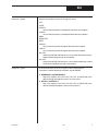
For your safety and information, when
CHAPTER 1
INTRODUCTION .............................................................................. 1 using this Manual we have highGeneral Description.......................................................................... 1 lighted NOTEs, CAUTIONs and
532 Auto/Manual Backup Station .................................................... 1 WARNINGs. Please heed these
Confirming What Is Included ........................................................... 2 safety and good practice notices for
Where to Begin ................................................................................. 2 the protection of you and your equipOverview of the 532 Modes ............................................................. 2 ment.
Where To Go Next ........................................................................... 2
Order Codes ..................................................................................... 3
CHAPTER 2
BASIC OPERATION ........................................................................ 4
532 Operator Interface ..................................................................... 4
Displays ................................................................................... 4
Icons ........................................................................................ 5
Keys ......................................................................................... 5
532 Operating Procedures ............................................................... 6
532 Alarm Operation ........................................................................ 7
Alarm Indication ....................................................................... 7
Alarm Acknowledgment ........................................................... 7
Latching Alarms ....................................................................... 8
Limit Sequence ........................................................................ 8
More on Alarms ....................................................................... 8
CHAPTER 3
HARDWARE SET UP ...................................................................... 9
Hardware Settings ............................................................................ 9
A. Process Variable Indicator Type ...................................... 10
B. Mechanical Relays ............................................................ 11
Hardware Adjustments ................................................................... 11
A. Accessing and Changing Jumpers ................................... 11
B. Adding or Changing Output Modules ................................ 12
CHAPTER 4
INSTALLATION & WIRING ........................................................... 15
System Planning ............................................................................ 15
A. Consider the Noise Factor ................................................ 15
B. Wiring Practice Resources ............................................... 15
Installation ...................................................................................... 15
A. Make the panel cutout ....................................................... 15
B. Establish a waterproof seal............................................... 16
C. Mount station into panel .................................................... 16
Input Wiring for the 532.................................................................. 17
A. AC Power ........................................................................... 17
B. Process Variable Indicator ................................................ 18
C. Digital Inputs ..................................................................... 19
D. Setpoint or Valve Position Indicator ................................. 19
Output Wiring for the 532 ............................................................... 20
A. CV Output .......................................................................... 20
B Mechanical Relay Output .................................................. 20
C Solid State Relay (Triac) Output ....................................... 20
D. DC Logic (SSR Drive) Output ........................................... 20
532 User’s Manual
Table of Contents
i
Contents
page
Wiring the Serial Communications Option ..................................... 21
Where to Go Next .......................................................................... 21
CHAPTER 5
SOFTWARE SET UP ..................................................................... 22
Mode Overview .............................................................................. 22
Menus ............................................................................................. 22
Smart Menus .................................................................................. 22
Set Up Procedures ......................................................................... 23
Step-by-Step Guide to Software Set Up ........................................ 24
CONFIG. ................................................................................ 24
LOCAL OUT. .......................................................................... 25
PV INPUT .............................................................................. 26
CUST. LINR. .......................................................................... 27
SP INPUT .............................................................................. 28
VP INPUT .............................................................................. 29
ALARMS ................................................................................ 29
SECURITY ............................................................................. 33
SER. COMM. ......................................................................... 33
OPERATION .......................................................................... 34
Software Set Up Charts ................................................................ 36
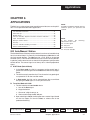
CHAPTER 6
APPLICATIONS ............................................................................. 41
532 Auto/Manual Station ............................................................... 41
Alarm Set Up .................................................................................. 42
A. Set the Alarm Type ........................................................... 42
B. Set the Alarm Parameters ................................................ 43
Digital Inputs .................................................................................. 47
PV, SP and VP Indication ............................................................. 48
A. Choose the Type of Display(s) ......................................... 48
B. Select the Process Variable Display Range .................... 48
C. Set Point Display Range ................................................... 49
D. Valve Position Display Range .......................................... 49
Input Linearization .......................................................................... 49
A. Thermocouple and RTD Linearization .............................. 49
B. Square Root Linearization ................................................ 50
C. Custom Linearization ........................................................ 50
Ramp to Control Value ................................................................... 52
Security .......................................................................................... 52
Process Variable Reading Correction ............................................ 53
Serial Communications .................................................................. 54
APPENDIX A
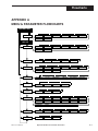
MENU & PARAMETER FLOWCHARTS ..................................... A-1
APPENDIX B
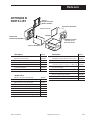
PARTS LIST ................................................................................ B-1
APPENDIX C
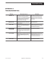
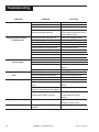
TROUBLESHOOTING ................................................................. C-1
APPENDIX D
CALIBRATION ............................................................................. D-1
ii
Table of Contents
532 User’s Manual
Contents
page
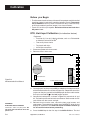
Regarding Calibration ...................................................................
RTD, VmA Input Calibration ........................................................
Thermocouple & Cold Junction Calibration .................................
Milliamp Output Calibration ..........................................................
Hardware Scan .............................................................................
D-1
D-2
D-3
D-4
D-6
APPENDIX E
SPECIFICATIONS ....................................................................... E-1
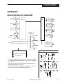
APPENDIX F
ISOLATION BLOCK DIAGRAM ................................................... F-1
532 User’s Manual
Table of Contents
iii
Contents
Figure ....... Title ................................................................................... Page
2.1 ............ 532 Operator Interface .............................................................. 4
2.2 ............ Before and After Acknowledging an Alarm ................................. 8
3.1 ............ Location of Printed Circuit Boards ............................................. 9
3.2 ............ The Microcontroller Circuit Board ............................................ 10
3.3 ............ The Option Circuit Board......................................................... 10
3.4 ............ The Power Supply Circuit Board .............................................. 10
3.5 ............ Representation of Module (view of bottom) ............................... 13
4.1 ............ 532 instrument panel and cutout dimensions ............................ 15
4.2 ............ Mounting Brackets ................................................................. 16
4.3 ............ 532 Rear Terminals ................................................................ 17
4.4 ............ Output Wiring for the 532 ........................................................ 20
4.5 ............ Serial Communications Terminals ........................................... 21
5.1 ............ Menu Flowchart for Set Up ...................................................... 22
5.2 ............ Independent Parameters versus Dependent Parameters .......... 23
5.3 ............ Keys to Enter and Move through Set Up Mode ......................... 23
6.1 ............ Alarm Examples .................................................................... 46
6.2 ............ Square Root Linearization Formula .......................................... 50
6.3 ............ Custom Linearization Curve .................................................... 51
D.1 ............ Flowchart to Access the Calibration Menus............................. D-1
D.2 ............ Microcontroller Circuit Board .................................................. D-2
D.3 ............ RTD, VmA Calibration Wiring ................................................. D-3
D.4 ............ Thermocouple & Cold Junction Calibration Wiring .................... D-3
D.5 ............ Milliamp Calibration Wiring ..................................................... D-5
D.6 ............ Flowchart for Access to Reset and Hardware Scan Menus ....... D-6
iv
Table of Contents
532 User’s Manual
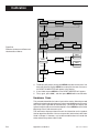
Introduction
CHAPTER 1
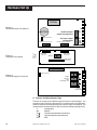
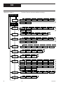
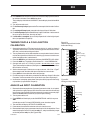
INTRODUCTION
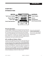
INPUTS
Two Process Variables
532
OUT
1 2
ALM
1 2
OUTPUTS
Control Outputs
Alarm(s)
Retransmission
Remote Setpoint
Digital Inputs
Serial Communications
Serial Communications
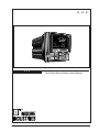
General Description
The 532 Auto/Manual Station ensures the integrity of your processes with
maximum reliability. Isolated inputs and outputs guard against electrical
interference, the front faces meet NEMA 4X standards for watertight operation, and solid metal housings and sturdy rubber keys enhance durability.
The station has three digital display areas, two of which offer up to 9 characters
of true alphanumerics. The bright, crisp vacuum fluorescent displays offer
better readability than any other display technology. Additional operator
friendly features include: custom programmable alarm messages, keys that
illuminate when in use and an easy-to-use menu system.
Thank you for selecting the 532
Auto/Manual Backup Station.
It is the most sophisticated instrument in its class, and will provide
you with years of reliable, troublefree performance.
532 Auto/Manual Backup Station
The 532 has been engineered to be the industry’s most user friendly and
comprehensive Auto/Manual Backup Station. The 532 provides automatic
and manual control backup for critical control loops. In Auto or Remote mode,
the control signal passes from the Host device through the 532 without any
degradation. A Host device may be a PLC, DCS or process controller. The 532
switches to Local mode upon keypad selection, digital input or loss of the
Host signal. The 532 generates a control signal based on a predetermined
control value (CV), or the last known CV from the Host. The operator can
modify the CV with the and keys. The 532 will transfer to Remote mode
upon keypad selection, opening of the digital input or return of the Host signal.
Removal of the 532 from its case or powering down while in Remote mode will
not disturb the Host signal; the 532 is not a point of failure!
532 User’s Manual
Chapter 1, Introduction
1
Introduction
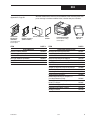
With your controller,
you should have received:
1.
2.
3.
4.
532 User’s Manual
Mounting hardware
Test sheet
Engineering unit adhesive
labels (1 sheet)
5. Terminal label
Confirming What Is Included
You can determine which outputs have been installed in your station by
comparing your product number to the Order Code on the next page. This
product number is printed on the label located on the top of the controller case.
Where to Begin
If you are a first time user of a 532 Auto/Manual Station, we recommend that
you read through the entire manual. A variety of special functions to enhance
your control capability are detailed throughout the manual.
Overview of the 532 Modes
NOTE:
This manual may refer to the 532
Auto/Manual Station as the “532” or
either simply as “the station.”
NOTE:
If you alter the factory configuration of the
modules, this product label code will no
longer be valid.
2
Operating
The 532 is in Operating Mode when you turn it on and usually
while operating. From this mode, you can initiate the transition
between Remote and Local modes, acknowledge alarms and
monitor conditions. You can also access parameters that
directly relate to the transfer functions.
Set Up
This sometimes referred to as configuration. In Set Up you
configure the basic function of the station, like input and output
assignments, alarm types and special functions.
Where To Go Next
•
First time users, continue to Chapter 2 for information on the operator
interface and basic controller operation.
•
•
Chapter 3 contains important installation guidelines.
Chapter 5 details the controller menus and parameters. Use the flowchart
in Appendix A as a graphic guideline when you configure your controller.
Chapter 1, Introduction
532 User’s Manual
Introduction
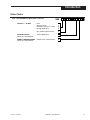
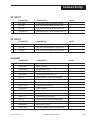
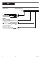
Order Codes
532 - AUTO/MANUAL BACKUP STATION
OUTPUT 1 — ALARM
OPTIONAL INPUTS
532 -
None
Mechanical relay
Solid state relay (triac) (1 amp)
DC logic (SSR drive)
0
1
3
4
One 4-20mA output included
2
Set of 3 digital inputs
D
RS-485 serial communications
S
2 1 1 0 B
0 0
ENTER "0" IF NOT DESIRED
SERIAL COMMUNICATIONS
ENTER "0" IF NOT DESIRED
532 User’s Manual
Chapter 1, Introduction
3
Operation
CHAPTER 2
BASIC OPERATION
The individual software and hardware options of your station determine which
information it will display. Compare the product number (on the product label) to
the Order Code in Chapter 1.
NOTE:
Any modifications to the factory settings
of the output modules will render the
product label code invalid.
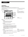
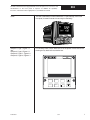
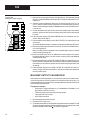
532 Operator Interface
532
Icons
OUT
1 2
ALM
1 2
1st Display
NOTE:
The 532 features smart menus; only
those messages relevant to your
hardware and software configuration
will appear. See Chapter 5 for details.
2nd Display
3rd Display
Location for
identification label
LOCAL
DISPLAY
HOST
MENU
ACK
Keys
FAST
Figure 2.1
532 Operator Interface
Displays:
1st Display
• 5 digits, seven segments. 15mm (0.6in) high.
•
•
Normally displays CV in tenths of a percent.
If PV option is chosen, will display PV.
2nd Display
• 9 characters, 14 segment alphanumeric. 6mm (0.25 in) high.
•
•
If only PV option is chosen, displays CV.
If only 2nd input option is chosen, shows SP or VP (valve position).
•
If PV and 2nd input options are chosen, automatically alternates
between CV and the SP (or VP) at 2 second intervals. Pressing the
or key to change the output value immediately stops the
alternating and displays the CV. Alternating resumes if there is no
key activity for 2 seconds.
During Set Up, displays configuration information.
•
3rd Display
• 9 characters, 14 segment. 6mm (0.25 in) high.
•
•
•
4
If no alarm messages are queued, displays user-selectable
station name.
If errors or alarms are queued, displays messages that alternate every
2 seconds.
NOTE:
If the station loses the PV, SP or VP
signal, “--------” will appear in place of
the numeric value in the 1st or 2nd
display. Refer to Appendix C for more
information.
During Set Up, displays configuration information.
Chapter 2, Basic Operation
532 User’s Manual
Operation
ALM
1
ALM
2
ALM
1 2
Icons:
ALM1 and ALM2 Icons:
Indicates respective alarm is active.
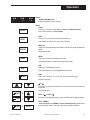
Keys:
LOCAL
Press key: Transfers station between Local and Remote modes.
LOCAL
Illuminated: Station is in Local mode.
HOST
Press key: Has no effect; used for indication only.
HOST
Illuminated: 532 senses CV signal from the Host.
DISPLAY
Press key: Exits the configuration menus and returns station to operation
mode.
DISPLAY
Key does not light.
MENU
Press key: Accesses the Operation menus.
MENU
Illuminated: Station is in Set Up (configuration) mode.
ACK
Press key: Acknowledges alarms.
ACK
Illuminated: When an acknowledgeable alarm exists.
FAST
FAST
Press key: Functions as a “shift” key; for use with other keys.
Key does not light.
or
Press key: Increases or decreases the value or selection of the current
parameter.
or
Keys do not light.
FAST
FAST
FAST
532 User’s Manual
+
FAST +
Press keys: Changes parameter value or selection with a larger increment.
+
+
/ FAST +
MENU
FAST + MENU
(Hold down FAST, press MENU) In Local or Remote mode, provides entry
into the Set Up mode. In Set Up, advances from Menu to Menu .
Chapter 2, Basic Operation
5
Operation
532 Operating Procedures
This is a quick guide to key operating functions of the 532.
1.
To change from REMOTE to LOCAL mode
a. Press the LOCAL key to shift from Remote to Local. The LOCAL key
remains lit while in Local mode.
b. The 532 stops passing the Remote (Host) signal, and transmits its own
signal. This will be either the last known Host signal or one of two
predetermined outputs.
c. If you have selected a predetermined CV, you may specify (during Set
Up) the rate of change from the remote value to the new value (also
known as a RAMP).
2. To change from LOCAL to REMOTE mode
a. Press the LOCAL key to shift from Local to Remote. The LOCAL key
will extinguish.
b. The 532 will stop transmitting its own signal and pass the signal from
the Host device to the final control element
c. The transfer will be direct unless a ramp rate was chosen during setup.
3. To change output values in LOCAL mode
a. Press LOCAL key to shift from Remote to Local.
b. Press
to increase, or
to decrease the CV value.
4. To override security
a. If someone attempts a locked operation, the word SECURITY appears
in the 2nd display, and the security code starting value (0) appears in
the 3rd display.
b. Select the security code using and . To “enter” the displayed value
as a code, leave the keys inactive for 2 seconds.
c. If no code was entered (value left at 0), the Security message
disappears and the station resumes operation.
NOTE:
For more information on Security
functions, see Chapter 6.
d. If the code is incorrect, INCORRECT appears in the 3rd display. After
2 seconds, the station returns you to step 4b to enter another code.
e. If the code is correct, CORRECT appears in the 3rd display. After 2
seconds, the displays clear and you have temporary access to all
previously locked features. Security will automatically rearm (lock) the
station once you leave the keys inactive for 1 minute.
f. If the Security Override Code is entered, RESET appears in the 3rd
display. After 2 seconds, the displays clear and the station’s security
functions are all reset to their factory defaults (all unlocked).
6
Chapter 2, Basic Operation
532 User’s Manual
Operation
NOTE:
Powering down the controller
acknowledges/clears all latched
alarms. When powering up, all alarms
will be reset according to their powerup configuration (see Chapter 6).
532 Alarm Operation
IMPORTANT NOTICE!
Alarms can be used to provide warnings of unsafe conditions.
Therefore, all 532 operators must know how the alarms are configured, how to react to alarm conditions, and the consequences of
acknowledging (noting and clearing) an alarm.
Alarm Indication
NOTE:
All alarms are internal alarms unless tied
to an output relay in the Set Up mode.
The 532 indicates alarms by:
• Lighting icons
•
•
Displaying messages; and
Lighting the ACK key, if an alarm is in an acknowledgeable state.
Alarm Acknowledgment
An alarm is acknowledgeable only when the ACK key is illuminated. To
acknowledge an alarm:
1. Press the ACK key to acknowledge Alarm 1. This clears the alarm and
releases the relay (if applicable).
2. Both the icon and message indicators disappear, and the relay (if applicable)
changes state.
3. If a second alarm is active and acknowledgeable, press the ACK key again
to acknowledge Alarm 2.
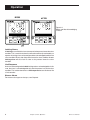
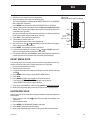
Figure 2.2 shows the controller face during an alarm condition, and then, after the
alarm has been acknowledged.
532 User’s Manual
Chapter 2, Basic Operation
7
Operation
BEFORE
AFTER
532
OUT
1
ALM
1
532
OUT
1
Figure 2.2
Before and After Acknowledging
an Alarm
LOCAL
DISPLAY
HOST
MENU
ACK
LOCAL
DISPLAY
FAST
HOST
MENU
ACK
FAST
Latching Alarms
A latching alarm will hold its alarm state even after the process leaves the alarm
condition. This is useful for stations that will not be continually monitored by an
operator. A latching alarm can be configured to be acknowledgeable while in the
alarm condition OR only after the process leaves the alarm condition. A nonlatching alarm will clear itself as soon as the process leaves the alarm
condition.
Limit Sequence
An alarm can be configured to be both latching and non-acknowledgeable. In this
case, the alarm is acknowledgeable only after the process has left the alarm
condition. This is often referred to as a limit sequence because it behaves like
a limit controller.
More on Alarms
For more on alarm types and set ups, see Chapter 6.
8
Chapter 2, Basic Operation
532 User’s Manual
Hardware Set Up
CHAPTER 3
HARDWARE SET UP
The configuration of the 532 hardware determines which outputs are available and
the types of indicator signals that will be used. Your station comes factory set
with the following:
• All the specified modules and options installed (see product label and compare
to Order Code in Chapter 1);
•
•
Process variable, setpoint and/or valve position inputs set to accept a
milliamp input;
Relay outputs set to normally open.
If you need to change any modules or any other settings, read the rest of this
chapter. Otherwise, move on to Chapter 4.
NOTE:
If you would like your controller
configured at the factory, please
consult an application engineer.
NOTE:
Any changes you make to the output
modules will render the code on the
product label invalid.
CAUTION!
Static discharge will cause damage to equipment. Always
ground yourself with a wrist grounding strap when handling
electronics to prevent static discharge.
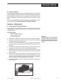
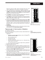
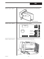
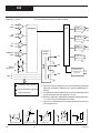
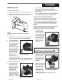
Hardware Settings
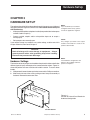
The locations of certain jumpers and module on the printed circuit boards will allow
different types of inputs and outputs to be connected to the stations. Figure 3.1
shows the position of these circuit boards inside the station. To access these
boards:
1. With power off, loosen the two captive front screws with a Phillips screwdriver.
NOTE:
Your hardware configuration will
influence the available software
options in Chapter 5.
2. Slide the chassis out of the case by pulling on front face plate assembly at
the bezel. Remove the two screws now.
MIC
BO ROCO
ARD
N TR
O
LLE
R
POW
BOA ER SUP
RD
PLY
Figure 3.1
Location of Printed Circuit Boards for
Hardware Configuration
OPTION BOARD
532 User’s Manual
Chapter 3, Hardware Set Up
9
Hardware Set Up
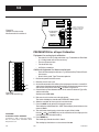
EPROM
Figure 3.2
The Microcontroller Circuit Board
TB2
5-Pin Connector
Female 22-Pin Connector
2ND
SP/VP Indicator
Jumper Configuration
PV Input Jumper
Configuration
Female 22-Pin Connector
V
MA
TC
TC
RTD
PV1
BATTERY
V
MA
Figure 3.3
The Option Circuit Board
front of
station
TB1
Male 22-Pin
Connector
Output 4
Male 22-Pin
Connector
4
Male 44-Pin
Connector
Module
Retention
Plate
over Outputs 1,2,3
3
2
1
NO J2 NC
4-Pin Connector
NO J1 NC
Figure 3.4
The Power Supply Circuit Board
NO J3 NC
Female 44-Pin Connector
Jumpers
NO and NC
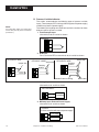
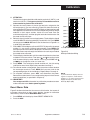
A. Process Variable Indicator Type
The 532 will accept several different types of Process Variable Signals. You
specify the type of signal by adjusting the PV jumper location on the Microcontroller Circuit Board, and setting the particular sensor range in the software. The
jumper locations for the process variable are marked as follows (see Figure 3.2).
V
Voltage signal
MA
Milliamp
TC
Thermocouple with downscale burnout
TC
Thermocouple with upscale burnout
RTD
RTD
10
Chapter 3, Hardware Set Up
532 User’s Manual
Hardware Set Up
B. Mechanical Relays
There is one output module socket on the Option Board (Figure 3.3), and three on
the Power Supply Circuit Board (Figure 3.4). The position of the jumper next to each
socket determines whether the relay is configured for Normally Open (NO) or
Normally Closed (NC). The output on the options board is always Normally Open
(NO).
On the 532, only the Output 1 relay (if used) may be configured for normally
open or normally closed. DO NOT make any changes to J2 and J3.
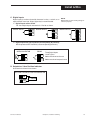
Hardware Adjustments
A. Accessing and Changing Jumpers
Jumper connectors either slip over adjacent pins, or have pins which insert into
adjacent holes. “Changing the jumper” means moving the jumper connectors to
alternate pins/holes.
Equipment needed:
• Needle-nose pliers (optional)
•
•
Phillips screwdriver (#2)
Wrist grounding strap
1. With power off, loosen two captive front screws with a Phillips screwdriver.
2. Slide the chassis out of the case by pulling on front face plate assembly at
the bezel. Remove the two screws now.
3. You will not need to disassemble the chassis to make these adjustments.
Refer to Figure 3.3 and Figure 3.4 to locate the jumper connector you want
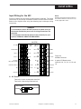
to change.
4. With either your fingers or the needle nose pliers, pull the jumper connector
straight up, as shown in Photo 1. Be careful not to bend the pins.
CAUTION!
Static discharge will cause damage to
equipment. Always ground yourself
with a wrist grounding strap when handling electronics to prevent static discharge.
5. Move the jumper connector over the desired location and press it straight
down, making sure it is seated firmly. Repeat steps 3 and 4 for any others you
wish to change.
6. When you are ready to reassemble the unit, align the boards on the chassis
with the cases's top and bottom grooves. Press firmly to slide the chassis into
the case. If you have difficulty, check that you have properly oriented the
chassis, and there are no screws interfering with the case.
7. Carefully insert and align screws. Tighten them until the bezel is seated firmly
against the gasket.
1. Removing jumpers
532 User’s Manual
Chapter 3, Hardware Set Up
11
Hardware Set Up
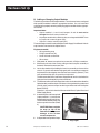
B. Adding or Changing Output Modules
The 532 has provisions for four output modules. The unit comes factory configured
with specified modules installed in appropriate locations. You can make field
adjustments by properly removing and/or plugging the modules into the appropriate sockets.
Important Notes:
• Output modules 2, 3 and 4 and Jumpers J2 and J3 must not be
changed from their factory installation.
•
•
Any output module with a sold state relay or analog module MUST have
its jumper set at normally open (NO).
Output 4 is always normally open (NO).
Three of the output sockets are located on the Power Supply Circuit Board. A fourth
output socket is located on the Option Board.
Equipment needed:
•
•
Wrist grounding strap
Phillips screwdriver (#2)
•
•
Small flat blade screwdriver
Wire cutters
1. With power off, loosen two captive front screws with a Phillips screwdriver.
2. Slide the chassis out of the case by pulling on front face plate assembly at
the bezel. Remove the two screws now.
3. Locate the retention clips holding the front face assembly to the rest of the
chassis. Pry apart these retention clips gently with a screwdriver to separate
the printed circuit board group from the front face assembly (Photo 2). Take
care not to break the clips or scratch the circuit board.
The Microcontroller Board and Power Supply Board remain attached to the
Operator Interface Assembly by wired connectors.
4. The Microcontroller and Power Supply board are attached to either side of the
Option board by male/female pin connectors. Use a gentle rocking motion and
carefully apply pressure to separate the larger two boards from the Option
Board (Photo 3).
Figures 3.2, 3.3 and 3.4 show the Microcontroller Board, Option Board and
Power Supply Board.
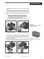
5. A retention plate and tie wrap hold
Output modules 1, 2, and 3 (on the
Power Supply board) firmly in place.
To remove the retention plate, snip
the tie wrap with wire cutter (Photo
4).
CAUTION! Always snip the
tie wrap on top of the
Retention Plate to prevent
damage to the surface
mount components.
6. A disposable tie wrap holds Output
2. Pry Clips
12
Chapter 3, Hardware Set Up
532 User’s Manual
Hardware Set Up
module 4 (on the Option board) in place. To remove the module, snip tie wrap
(Photo 5).
7. Inspect each module before installation to make sure the pins are straight (see
Figure 3.5). Align the pins with the socket holes and carefully insert the
module. Press down on the module to seat it firmly on the board (Photo 6).
8. Replace tie wraps for the Retention Plate and for Output Module 4 with new
ones.
Failure to use these devices may result in a loosening of the
module and eventual failure. If you ordered a module separately, it should have come with a tie wrap. An extra set of tie
wraps is available by ordering Part #535-665.
9. To reassemble the unit: Align the connector pins on the Option Board with the
CAUTION!
Do not scratch the boards or bend the
pins of the connectors.
3. Separate Boards
4. Remove Retention Plate
connector sockets on the Microcontroller and Power Supply boards. Squeeze
them together, making certain all three are properly seated against one
another. Check along the side edges for gaps. Also, check that the cable
assemblies are not pinched.
10. Align the board assembly with the front face assembly, with the Option board
at the bottom (see Figure 3.1). Reinstall the retention clips. Align the boards
5. Snip Tie Wrap
532 User’s Manual
Figure 3.5
Representation of Module (view of
bottom)
6. Add/Change Module
Chapter 3, Hardware Set Up
13
Hardware Set Up
into the slots of the front face assembly and the clips will snap into place.
11. When you are ready to reassemble the unit, align the boards on the chassis
with the top and bottom grooves on the case. Press firmly to slide the chassis
into the case. If you have difficulty, check that you have properly oriented the
chassis, and there are no screws interfering with the case.
12. Carefully insert and align screws. Tighten them until the bezel is seated firmly
against the gasket.
After you have configured the hardware, you may go on to Chapter 4 for installing
and wiring the controller.
14
Chapter 3, Hardware Set Up
532 User’s Manual
Install & Wire
CHAPTER 4
INSTALLATION & WIRING
The 532 Auto/Manual Station is thoroughly tested, calibrated and “burned
in” at the factory, so your station is ready to install. But before you begin,
read this chapter thoroughly and take great care in planning your system.
A properly designed system can help prevent problems such as electrical
noise disturbances and dangerous conditions.
System Planning
A. Consider the Noise Factor
•
For improved electrical noise immunity, install the station as far
away as possible from motors, relays and other similar noise
generators.
•
Do not run low power (sensor input) lines in the same bundle as AC
power lines. Grouping these lines in the same bundle can create
electrical noise interference.
CAUTION!
For safety consideration, DO NOT run
low power (sensor input) lines in the
same bundle as AC power lines.
B. Wiring Practice Resources
An excellent resource about good wiring practices is the IEEE Standard
No. 518-1982 and is available from IEEE, Inc., 345 East 47th Street,
New York, NY 10017, (212) 705-7900.
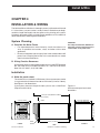
Installation
A. Make the panel cutout
The station fits in a standard 1/4 DIN cutout. You may mount your station
in any panel with a thickness from .06 to .275 inches (1.5mm to 7.0mm).
See Figure 4.1 for dimensions.
If you make a mistake in the panel cutout, you can use a “Goof Plate”
(Repair Part #512-014).
Figure 4.1
532 instrument panel and cutout
dimensions
7.180 in (182.37mm) OVERALL LENGTH
1.180 in (29.97mm)
PANEL
3.770 in (95.76mm)
3.622 in (92.00mm) MIN.
3.653 in (92.80mm) MAX.
FRONT
532 User’s Manual
3.585 in (91.06mm)
3.622 in (92.00mm) MIN.
3.653 in (92.80mm) MAX.
3.770 in (95.76mm)
532
PV2
OUT
1 2
ALM
1 2
BEZEL
GASKET
6.000 in (152.40mm)
SIDE
Chapter 4, Installation & Wiring
CUTOUT
15
Install & Wire
B. Establish a waterproof seal.
The station front face (keys, display, and bezel) are NEMA 4X rated
(waterproof). To obtain a waterproof seal between the station and the
panel, make sure:
1. The panel cutout is precise;
2. You use a fresh gasket;
3. The edge of the cutout is free from burrs and “waves;”
4. The case of the station are centered in the cutout.
If you require a waterproof seal but have difficulty with these requirements, apply a bead of caulk or silicone sealant behind the panel
around the perimeter of the case.
C. Mount station into panel:
The instrument enclosure mounting MUST BE GROUNDED
according to CSA Standard C22.2 No. 0.4.
You will need a long Phillips screw driver (#2).
1. Turn the instrument with the back towards you. Now slide the
gasket around the back of the case, all the way up to the bezel.
2. With the bezel gasket in place, insert the station into the panel
cutout from the front of the panel.
3. From behind the panel, insert the mounting clips (one on each
side), as shown in Figure 4.2.
4. Gradually tighten the mounting bracket screws.
5. Tighten the screws securely and check bezel gasket to ensure a
tight, even seal.
BEZEL
Figure 4.2
Mounting Brackets
HOUSING
Slide on
gasket from
this end.
MOUNTING BRACKET
(1 EA. SIDE)
16
Chapter 4, Installation & Wiring
532 User’s Manual
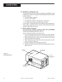
Install & Wire
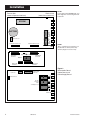
Input Wiring for the 532
Figure 4.3 shows the rear terminal configuration for the 532. The actual
instrument has only the top and bottom numbers of each column marked.
Refer to this diagram when using the following input and output wiring
instructions.
NOTE:
All wiring and fusing should conform to
the National Electric Code and to any
locally applicable codes.
WARNING!
To avoid electric shock, DO NOT connect AC power wiring at
the source distribution panel until all wiring connections are
complete.
To avoid shock hazard and reduced noise immunity for your
system, TERMINAL 9 MUST BE GROUNDED.
532 (TOP)
EARTH
GND
DIN
GND
17
25
NC
NC
DIN 1
18
26
COMM–
11
NC
DIN 2
19
27
COMM+
4
12
NC
DIN 3
20
28
SP IND.–
CV OUT–
LOC. OUT CALIB.–
5
13
NC
NC
21
29
SP IND.+
LOC OUT CALIB.+
6
14
CV IN+
NC
22
30
RTD 3RD
NC
7
15
CV IN–
CJ –
23
31
PVIND.–
CV OUT+
8
16
NC
CJ +
24
32
PV IND.+
AC LINE
1
9
AC NEUTRAL
2
10
OUT 1–
3
OUT 1+
Figure 4.3
532 Rear Terminals
A special PC Board covers
terminals 5, 6, 7, 8, 13, 14, 15, and
16.
A. AC Power
Terminals 1 and 2 are the power terminals.
Terminal 9 is the earth ground terminal.
AC POWER
POWER
532 User’s Manual
1
9
GROUND
2
Chapter 4, Installation & Wiring
17
Install & Wire
B. Process Variable Indicator
NOTE:
Use a 0.5 Amp, 250 V, fast-acting fuse
in line with your AC power connection
(terminal 1).
The station accommodates the following types of process variable
inputs: Thermocouple, RTD , Voltage, Milliamp (external power supply)
and Milliamp (internal power supply).
The following wiring diagrams show how to wire the stations for these
different types of process variable.
1. Thermocouple Input
Use terminals 30, 31 and 32 as shown.
T/C INPUT
30
31
32
–
+
2. RTD Input
For 2, 3 or 4 wire RTD, use terminals 30, 31 and 32 as shown.
RTD INPUT 2-WIRE
RTD INPUT 3-WIRE
Jumper wire
Third leg
of RTD
30
31
32
RTD INPUT 4-WIRE
Same color
RTD
30
30
31
31
32
Same color
Third leg
of RTD
32
DO NOT connect 4th leg
Same color
3. Voltage Input
Use terminals 31 and 32 as shown.
VOLTAGE INPUT
–
+ Transmitter
31 –
32 +
4. Milliamp Input -External Power Supply
Use terminals 31 and 32 as shown.
mA INPUT
2-Wire transmitter with separate power supply
18
31
– External +
Power Supply
32
–Transmitter +
Chapter 4, Installation & Wiring
532 User’s Manual
Install & Wire
C. Digital Inputs
Digital input(s) can be activated by closure of a relay, a switch, or an
open collector transistor. Signal-type relay is recommended.
NOTE:
Digital inputs require wetting voltage to
function properly.
1. Digital Inputs with a switch
For 1 to 3 digital inputs use terminals 17 to 20 as shown.
DIGITAL INPUT 1
17
DIGITAL INPUT 2
17
DIGITAL INPUT 3
18
18
17
18
19
19
20
2. Digital Inputs with Open Collector (resistor)/Relay (dry contact)
DIN X represents DIN 1 to DIN 3 (use corresponding terminals).
OPEN COLLECTOR
RELAY
17
17
DIN
X
DIN
X
Three Digital Inputs
11mA Typical
50ohm maximum resistance
50ohm maximum loop resistance
D. Setpoint or Valve Position Indicator
Use terminals 28 and 29 as shown.
SETPOINT OR VALVE POSITION INDICATOR
28
–
29 +
532 User’s Manual
–
+ Source
Chapter 4, Installation & Wiring
19
Install & Wire
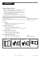
Output Wiring for the 532
•
Output 1 is available for use as an alarm with installation of a
Mechanical relay or Solid State Relay (Triac) module.
•
•
The 532 is factory configured with an Analog module in Output 2.
The 532 is factory configured with Mechanical relays in Outputs 3 and 4.
•
•
The 532 cannot be wired for retransmission.
A small PC board fits over rear terminals 5, 6, 7, 8, 13, 14, 15 & 16.
The following instructions explain how to properly wire the 532 for any
particular output module. If you do not know which module(s) have been
installed in your station, compare the product number on the product label
with the Order Code in Chapter 1.
To add or change position of jumpers or output modules, refer to
Chapter 3.
NOTE:
Any modifications to the factory settings
of the output modules will render the
product label code invalid.
A. CV Output
•
Use terminals 5 and 8 for CV Output as shown in Figure 4.4.
•
Use terminals 14 and 15 for CV Input
B Mechanical Relay Output
•
•
Use terminals 3 and 4 as shown in Figure 4.4.
Jumper J1 can be set to normally open (NO) or normally closed
(NC) as desired.
C Solid State Relay (Triac) Output
•
Use terminals 3 and 4 as shown in Figure 4.4.
•
Jumper J1 must be set to normally open (NO).
D. DC Logic (SSR Drive) Output
•
•
MECHANICAL RELAY
CV OUTPUT
_
6
CV
Line Power
3
3
_
4
+
Load
7
4
DC LOGIC (SSR DRIVE)
SSR (TRIAC)
Line Power
5
8
Figure 4.4
Output Wiring for the 532
Use terminals 3 and 4 as shown in Figure 4.4.
Jumper J1 must be set to normally open (NO).
+
3
_
_
4
+
+
Load
Load
+
Recommend use of both MOV and snubber Recommend use of both MOV and snubber
20
Chapter 4, Installation & Wiring
532 User’s Manual
Install & Wire
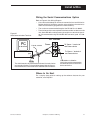
Wiring the Serial Communications Option
Refer to Figure 4.5 for Wiring Diagram.
•
•
•
Figure 4.5
Serial Communications Terminals
Use a twisted shielded pair of wires to connect the host and field units.
Belden #9414 foil shield has superior noise rejection characteristics.
#8441 braid shield 22-gauge wire has more flexibility.
The maximum recommended length of the RS-485 line is 4000 ft.
Termination resistors are required at the host and the last device on the
line. Some RS-485 cards/converters already have a terminating resistor. We recommend using RS-232/RS-485 converter (prod. no. 500485).
532 Terminals
PC
or other host
Twisted, shielded
RS-485
port
Comm –
26
Comm +
27
The shield needs to be connected continuously but only tied to
one ground at the host. Failure to follow these proper wiring practices could result in transmission errors and other communications
To "Comm –" terminal of
next Powers device
To "Comm +" terminal of
next Powers device
Use a 60ohm to 100ohm
terminating resistor connected to
the two data terminals of the final
device on the line.
Where to Go Next
For a step-by-step guide on setting up the software features for your
controller, see Chapter 5.
532 User’s Manual
Chapter 4, Installation & Wiring
21
Software Set Up
CHAPTER 5
SOFTWARE SET UP
Mode Overview
The 532 will be in Operating Mode upon power up, and will remain in Operating
Mode most of the time it is performing its functions. This is not the same as
the OPERATIONS menu.
NOTE TO ALL USERS:
Be sure to read and understand the next
two pages, which contain important information on how to use this guide to
help you to set up the instrument. The
Parts of the Menu section explains the
graphic used in the Set Up and Tuning
configuration sections.
In Set Up Mode, you can access menus of operation parameters that affect
the display and adjustment of the stations.
Figure 5.1 illustrates the relationships between the different modes of the 532
station, and the different Set Up menus.
Menus
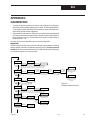
Figure 5.1
Menu Flowchart for Set Up
OPERATING
CONFIG.: To configure the input and output hardware assignments.
LOCAL OUT.: To configure the local output control.
SP INPUT: To configure the set point indicator.
VP INPUT: To configure the valve position indicator.
ALARMS: To configure alarms.
SECURITY: To configure the security function.
Smart Menus
This chapter outlines, in sequence, all menus, parameters, and selections
available for the 532 station. However, the “smart menu” feature of the
stations allows only those menu and Parameters to appear that are relevant
to your hardware and software configuration, i.e., parameters which do not
apply to your application will not appear on your station’s display.
DISPLAY
for Operating
OPERATIONS
MENU + FAST
for Set Up
SET UP
CONFIG.
LOCAL OUT.
PV INPUT
CUST. LINR.
SP INPUT
VP INPUT
ALARMS
SECURITY
SER. COMM.
22
Chapter 5, Software Set Up
MENU
for Operations
MENU + FAST
to toggle from menu block to menu block in set up
SER. COMM.: To configure serial communications.
OPERATIONS: To make adjustments to the transition [between Remote
(Host) and Local control] functions of the station.
DISPLAY or ACK to return to Operating
PV INPUT: To configure the process variable (PV) indicator.
CUST. LINR: To configure the custom linearization curve for the PV indicator.
MENU + FAST for Set Up
A menu is a group of Set Up parameters. The name of a menu appears in the
2nd display of the 532 station during your set up. Once inside a menu, the
different parameters will appear in the 2nd display. The values/options for
each parameters will appear in the 3rd display. On the station, the menu name
appears in the display at the beginning of the cycle of the menu.
These are the possible menu for your station, and their applications.
532 User’s Manual
Software Set Up
PV TYPE
INDICATOR
(D)
NONE
Figure 5.2
Independent Parameters versus
Dependent Parameters
1. Parameters that apply to all configurations of the 532 appear in this
manual as a white on white box (Figure 5.2, left portion). These
parameters are independent of your configuration.
2. Parameters that depend on the configuration of the individual station
appear as a black on white box (Figure 5.2, right portion ).
Be aware that changing one parameter’s selection (or value) may affect
another parameter. See the PV INPUT menu section for an example on how
this can affect your low and high range values.
Set Up Procedures
On the bottom of each page is a guide to the keypad, to use during the Set
Up procedure.
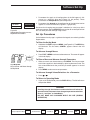
To Enter the Set Up Mode
1. Hold down the FAST and press MENU. (see Figure 5.3). The MENU key
will illuminate. The first menu, CONFIG., appears alone in the 2nd
display.
To Advance through Menus
MENU
2. Press FAST + MENU to advance to the next menu. The name will appear
in the 2nd display.
FAST
MENU
Figure 5.3
Keys to Enter and Move through
Set Up Mode
To Enter a Menu and Advance through Parameters
1. When you reach your chosen menu, press MENU. The first parameter
of this menu appears in the 2nd display, replacing the menu name. The
first values/selection for the particular parameter appears in the 3rd
display.
2. Press MENU to advance to next parameter.
To Advance through Values/Selections for a Parameter
1. Press
or .
To Return to Operating Mode
1. If you are in Set Up Mode, press the DISPLAY key. The 532 will return
to Operation Mode.
WARNING!!
Scrolling through the choices to make selections will affect the
operation of the instrument since changes to parameter selections
occur in “real time” or immediately.
DO NOT MAKE ANY CHANGES WHILE ON LINE (DURING
OPERATION).
532 User’s Manual
DISPLAY
Next Parameter
MENU
Next Block
FAST
+
Chapter 5, Software Set Up
MENU
Next value
▲
or
▲
Escape to Operation Mode
23
Software Set Up
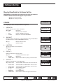
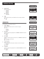
Step-by-Step Guide to Software Set Up
REMEMBER: Only parameters and selections relevant to your hardware
and other software selections will appear on your station.
(D) Indicates Default Setting
(R) Indicates a range of values
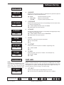
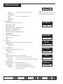
CONFIG
CONFIG.
For configuring the input and output hardware assignments.
INDICATOR
INDICATOR
Enables indicator for PV and/or a 2nd input.
2.
(D) NONE
No display
•
Display Process Variable
PV
NONE
•
2ND
Enable 2ND INPUT parameter
•
PV/2ND
Display PV and enable 2ND INPUT
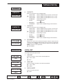
2ND INPUT
2ND INPUT
Chooses indicator for 2nd input, a retransmitted VP or SP (provided 2ND or
PV/2ND selection is made in INDICATOR parameter).
3.
(D) VP
Display Valve Position
•
Display Setpoint
SP
VP
LINE FREQ
LINE FREQ
Specifies the power source frequency
(D) 60 Hz
•
4.
60
50 Hz
OUTPUT 1
OUTPUT 1
Defines the function of the first output.
5.
(D) OFF
Completely deactivates output
•
ALARM
Digital only
•
COMM. ONLY
Output addressable only through communications
OFF
CONTACT 1
CONTACT 1
Defines the operation of the 1st digital input.
(D) LOCAL.LAST
Switch to Local, hold last out value seen from host
•
LOCAL.PRE1
Switch to Local, set LOCAL OUT to Preset 1 value
•
LOCAL.PRE2
Switch to Local, set LOCAL OUT to Preset 2 value
•
ALARM ACK.
Acknowledges alarms
•
UP KEY
Remote
function
•
DOWN KEY
Remote
function
•
COMM.ONLY
Makes status readable through communicatoins.
Escape to Operation Mode
24
DISPLAY
Next Parameter
MENU
Next Block
Chapter 5, Software Set Up
FAST
LOCAL.LAST
+
MENU
Next value
▲
or
▲
1.
532 User’s Manual
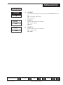
Software Set Up
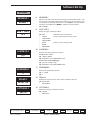
CONFIG
CONTACT 2
6.
Defines the operation of the 2nd digital input.
•
LOCAL.PRE1
CONTACT 3
7.
LOCAL.LAST
Switch to Local, hold last out value seen from host
(D) LOCAL.PRE1
Switch to Local, set LOCAL OUT to Preset 1 value
•
LOCAL.PRE2
Switch to Local, set LOCAL OUT to Preset 2 value
•
ALARM ACK.
Acknowledges alarms
•
UP KEY
Remote
function
•
DOWN KEY
Remote
function
•
COMM.ONLY
Makes status readable through communications.
CONTACT 3
Defines the operation of the 3rd digital input.
LOCAL.PRE2
STN.NAME
CONTACT 2
8.
•
LOCAL.LAST
Switch to Local, hold last out value seen from host
•
LOCAL.PRE1
Switch to Local, set LOCAL OUT to Preset 1 value
(D) LOCAL.PRE2
Switch to Local, set LOCAL OUT to Preset 2 value
•
ALARM ACK.
Acknowledges alarms
•
UP KEY
Remote
function
•
DOWN KEY
Remote
function
•
COMM.ONLY
Makes status readable through communications.
STN.NAME
Allows you to enter a nine character message to name the station. The first
character of the 3rd display will be flashing. Press arrow keys to scroll through
character set. Press FAST to enter the selection and move to next digit. Press
MENU to advance to next parameter.
BYPASSER
(D) BYPASSER
LOCAL OUT.
LOCAL OUT.
To configure the local output control.
LOW LIMIT
1.
Selects how low the output can be manually adjusted.
(R) -5.0% to 105%
0.0
(D) 0.0%
2.
Selects how high the output can be manually adjusted.
(R) -5.0% to 105%
100.0
PWR.UP:MODE
(D) 100.0%
3.
532 User’s Manual
PWR.UP:MODE
Selects the power-up mode.
(D) LAST
LAST
DISPLAY
HIGH.LIMIT
Next Parameter
MENU
Next Block
FAST
+
Chapter 5, Software Set Up
MENU
Next value
▲
or
▲
HIGH.LIMIT
Escape to Operation Mode
LOW LIMIT
25
Software Set Up
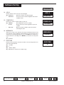
CONFIG
4.
•
LOCAL
•
REMOTE
PWR. UP:OUT.
PWR.UP:OUT
Selects the power-up output for the 532 in local mode.
(R) -5.0% to 105.0%
LAST OUT
(D) LAST OUT
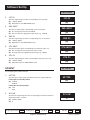
PV INPUT
PV INPUT
For configuring the process variable (PV) input. The whole menu appears only if
PV indicator is enabled.
PV TYPE
PV TYPE
Selects the particular sensor or input range.
(D)
USE THE ARROW KEYS TO MAKE APPROPRIATE SELECTION BASED ON YOUR PROCESS VARIABLE TYPE
2.
T/C Input:
RTD Input:
Voltage Input:
Current Input:
•
•
•
•
•
•
•
(D)
•
•
•
(D) DIN RTD
•
JIS RTD
•
SAMA RTD
(D)
•
•
•
•
•
•
(D) 4-20mA
•
0-20mA
J T/C
E T/C
K T/C
B T/C
N T/C
R T/C
S T/C
T T/C
W T/C
W5 T/C
PLAT.II T/C
1-5V
0-5V
0-10mV
0-30mV
0-60mV
0-100mV
+/-25mV
CAUTION!
Changing certain parameter
selections may affect other parameter values. Be careful when
changing parameters out of presented order.
DEG. F/C/K
DEG. F/C/K
Selects the temperature unit if using a thermocouple or RTD.
(D) FAHR.
3.
•
CELSIUS
•
KELVIN
FAHR.
DECIMAL
DECIMAL
Specifies the decimal point position.
For V/mA Input:
For RTD Input:
(D) XXXXX
(D) XXXXX
•
XXXX.X
•
•
XXX.XX
•
XX.XXX
•
X.XXXX
Escape to Operation Mode
26
DISPLAY
XXXXX
XXXX.X
Next Parameter
MENU
Next Block
Chapter 5, Software Set Up
FAST
+
MENU
Next value
▲
or
▲
1.
532 User’s Manual
Software Set Up
PV INPUT
4.
LINEARIZE
LINEARIZE
Specifies how to linearize the input. For V/mA Input only (Thermocouple and
RTD inputs are automatically linearized).
NONE
5.
LOW RANGE
(D) NONE
Normal linearization (2 point)
•
SQR. ROOT
Square root linearization
•
CUSTOM
15-point custom linearization curve
LOW RANGE
Specifies the engineering unit value corresponding to the lowest input value,
e.g. 4mA.For V/mA input only.
(D)
(R) –9999 to 99999, Maximum value is HI RANGE
(D) Dependent on the input selection.
6.
HI RANGE
HI RANGE
Specifies the engineering unit value corresponding to the highest input value,
e.g. 20mA. For V/mA input only.
(D)
(R) –9999 to 99999, minimum value is LOW RANGE
(D) Dependent on the input selection
7.
FILTER
(R) 0 to 120 seconds
0
(D) 0
8.
PV OFFSET
(R) –9999 to 99999
(D) 0
9.
PV GAIN
(R) 0.100 to 10.000
(D) 1.000
CUST.LINR.
CUST. LINR.
NOTE:
If you make any modifications to a set
curve, you must re-enter all points in
order, from 1 to X. Use the Set Up
Charts on page 36 to record your data.
1ST. INPUT
PV GAIN
Defines the gain to the process variable. For V/mA input only.
1.000
Defines a custom linearization curve for the process variable input. You need to
specify each of the curve’s 15 points. The first two points define the slope of the
curve (positive or negative). All subsequent points must support this slope, i.e.,
the curve must be ever-increasing or ever-decreasing.
1.
1ST. INPUT
Specifies the input signal corresponding to the first point.
(D) The low end of the appropriate input range (e.g., 4.00mA)
DISPLAY
Next Parameter
MENU
Next Block
FAST
+
Chapter 5, Software Set Up
MENU
Next value
▲
or
▲
(D)
532 User’s Manual
PV OFFSET
Defines the offset to the process variable in engineering units.
0
Escape to Operation Mode
FILTER
Defines the setting for the low pass input filter.
27
Software Set Up
CUST.LINR.
2.
1ST. PV
1ST. PV
Specifies engineering unit value corresponding to the first point.
(R) –9999 to 99999
(D)
(D) Dependent on the LOW RANGE value
3.
2ND. INPUT
2ND. INPUT
Specifies the input signal corresponding to the second point.
(R) Any value greater than the 1ST. INPUT
(D)
(D) The low end of the appropriate input range (e.g., 4.00mA)
4.
2ND. PV
2ND. PV
Specifies engineering unit value corresponding to the second point.
(R) –9999 to 99999
(D)
(D) Dependent on the LOW RANGE value
5.
XTH. INPUT
XTH. INPUT
Specifies the input signal corresponding to the Xth point (up to 15).
(R) Any value greater than the previous (XTH-1) input.
(D)
(D) The high end of the appropriate input range (e.g. 4.00mA)
6.
XTH. PV
XTH. PV
Specifies engineering unit value corresponding to Xth point (up to 15).
(R) –9999 to 99999
(D)
(D) Dependent upon the LOW RANGE value
SP INPUT
SP INPUT
For configuring the setpoint indicator.
1.
SP TYPE
SP TYPE
Specifies type of input signal that will be used for the setpoint indicator.
If the jumper is in the mA position:
(D)
(D) 4-20mA
•
0-20mA
If the jumper is in the V position:
(D) 1-5V
•
2.
0-5V
SP LOW
SP LOW
Specifies the engineering unit value corresponding to the lowest setpoint indicator input value, e.g. 4mA.
0
(R) -9999 to 99999
(D) 0
28
DISPLAY
Next Parameter
MENU
Next Block
Chapter 5, Software Set Up
FAST
+
MENU
Next value
▲
or
▲
Escape to Operation Mode
532 User’s Manual
Software Set Up
SP INPUT
3.
SP HIGH
SP HIGH
Specifies the engineering unit value corresponding to the highest setpoint
indicator input value, e.g. 20mA.
1000
(R) -9999 to 99999
(D) 1000.
4.
SP DISPLAY
SP DISPLAY
Selects whether to display SP as an actual setpoint (SP) or as a deviation
from the current PV indicator value (PV–SP).
SETPOINT
(D) SETPOINT
•
VP INPUT
DEVIATION
VP INPUT
For configuring the valve position indicator.
1.
VP TYPE
VP TYPE
Specifies type of input signal that will be used for the valve position indicator.
If the jumper is in the mA position:
(D)
(D) 4-20mA
•
NOTE:
You may configure you station for SP
Input or VP Input, but not both.
VP LOW
0-20mA
If the jumper is in the V position:
(D) 1-5V
•
2.
0-5V
VP LOW
Specifies the engineering unit value corresponding to the lowest valve position indicator input value, e.g. 4mA.
0
(R) -9999 to 99999.
(D) 0
VP HIGH
3.
VP HIGH
Specifies the engineering unit value corresponding to the highest valve
positon indicator input value, e.g. 20mA.
1000
(R) -9999 to 99999.
(D) 1000
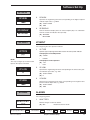
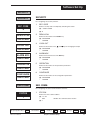
ALARMS
ALARMS
For configuring alarms.
1.
Defines the type of alarm for alarm 1.
(D) OFF
OFF
Escape to Operation Mode
532 User’s Manual
DISPLAY
ALM. TYPE:1
Next Parameter
MENU
Deactivates the first alarm
Next Block
FAST
+
Chapter 5, Software Set Up
MENU
Next value
▲
or
▲
ALM.TYPE:1
29
Software Set Up
ALARMS
2.
•
LOCAL
•
HIGH ALRM.
•
LOW ALARM
•
RATE
•
BAND
•
DEVIATION
NOTE:
Band and Deviation Alarm choices appear only if you use SP Indication.
Causes an alarm when in local control
Selects a rate-of-change alarm
ALARM SP:1
ALARM SP:1
Specifies the alarm set point for alarm 1.
If ALM. TYPE:1 = RATE
(D)
(R) -9999 to 99999
(D) Dependent on the LOW RANGE value.
IF ALM. TYPE:1 is any other type
(R) process variable range
(D) Dependent on the LOW RANGE value
DEADBAND:1
DEADBAND:1
Defines the deadband for alarm 1.
(R) 1 to 9999
2
(D) 2.
4.
RELAY:1
RELAY:1
Defines the state of the relay in the alarm condition for alarm 1.
(D) RELAY ON
•
5.
RELAY ON
RELAY OFF
LATCHING:1
LATCHING:1
Defines the latching sequence of alarm 1.
(D) LATCH
•
6.
LATCH
NO LATCH
ACK.:1
ACK.:1
Defines whether alarm 1 may be acknowledged.
7.
(D) ENABLED
Allows the alarm to be acknowledged
•
Prevents existing alarm from being acknowledged
DISABLED
ENABLED
POWER UP:1
POWER UP:1
Defines how alarm 1 will be treated on power up.
(D) NORMAL
Alarm depends on process variable
•
ALARM
Power up in alarm regardless of PV
•
DELAYED
Must leave alarm condition and reenter before
activating the alarm
Escape to Operation Mode
30
DISPLAY
Next Parameter
MENU
Next Block
Chapter 5, Software Set Up
NORMAL
FAST
+
MENU
Next value
▲
or
▲
3.
532 User’s Manual
Software Set Up
ALARMS
MESSAGE:1
8.
MESSAGE:1
Allows you to enter a nine character message associated with alarm 1. The
first character of the 3rd display will be flashing. To enter message, press
arrow keys to scroll through character set. Press FAST to enter the selection
and move to next digit. Press MENU to advance to next parameter.
ALARM 1
(D) ALARM 1
ALM. TYPE:2
9.
Defines the type of alarm for alarm 2.
OFF
ALARM SP:2
ALM. TYPE:2
(D) OFF
Deactivates the second alarm
•
LOCAL
Causes an alarm when in local control
•
HIGH ALRM.
•
LOW ALARM
•
RATE
•
BAND
•
DEVIATION
Selects a rate-of-change alarm
10. ALARM SP:2
Specifies the alarm set point for alarm 2.
If ALM. TYPE:2 = RATE
(D)
(R) -9999 to 99999
(D) Dependent on the LOW RANGE value.
IF ALM. TYPE:2 is any other type
(R) process variable range
(D) Dependent on the HIGH RANGE value
DEADBAND:2
11. DEADBAND:2
Defines the deadband for alarm 2.
(R) 1 to 9999
2
(D) 2
12. RELAY:2
Defines the state of the relay in the alarm condition for alarm 2.
(D) RELAY ON
RELAY ON
LATCHING:2
•
13. LATCHING:2
Defines the latching sequence of alarm 2.
(D) LATCH
LATCH
Escape to Operation Mode
532 User’s Manual
DISPLAY
RELAY OFF
•
Next Parameter
NO LATCH
MENU
Next Block
FAST
+
Chapter 5, Software Set Up
MENU
Next value
▲
or
▲
RELAY:2
31
Software Set Up
ALARMS
14. ACK.:2
ACK.:2
Defines whether alarm 2 may be acknowledged.
(D) ENABLED
Allows the alarm to be acknowledged
•
Prevents the alarm acknowledgment while alarm
condition exists.
DISABLED
ENABLED
15. POWER UP:2
POWER UP:2
Defines how alarm 2 will be treated on power up.
(D) NORMAL
Alarm depends on process variable
•
ALARM
Always power up in alarm regardless of process
variable
•
DELAYED
Must leave alarm condition and reenter before
activating the alarm
NORMAL
16. MESSAGE:2
MESSAGE:2
Allows you to enter a nine character message associated with alarm 2. The
first character of the 3rd display will be flashing. To enter message, press
arrow keys to scroll through character set. Press FAST key to enter the selection and move to next digit. Press MENU key to advance to next parameter.
ALARM 2
(D) ALARM 2
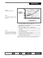
17. RATE TIME
RATE TIME
Defines the time period in seconds over which a rate-of-change alarm condition will be determined.
5
(R) 1 to 3600
(D) 5
(R) –9999 to 99999
(D) Dependent on the process variable range
32
DISPLAY
Next Parameter
MENU
Next Block
Chapter 5, Software Set Up
FAST
+
MENU
Next value
▲
or
▲
Escape to Operation Mode
532 User’s Manual
Software Set Up
SECURITY
SECURITY
SECURITY
For configuring the security function.
SEC. CODE
1.
SEC. CODE
Defines security code for temporarily unlocking the station.
(R) –9999 to 99999
0
(D) 0
REM./LOCAL
2.
Defines lockout status of the LOCAL key.
(D) UNLOCKED
UNLOCKED
LOCAL OUT
•
3.
•
4.
keys for changing the output.
LOCKED
ALARM ACK.
(D) UNLOCKED
•
5.
LOCKED
OPERATION
Defines lockout status of the operations parameters.
(D) UNLOCKED
•
6.
LOCKED
CONFIGURE
Defines lockout status of the configuration parameters.
(D) UNLOCKED
UNLOCKED
SER.COMM.
and
Defines the lockout status of the ACK key.
UNLOCKED
CONFIGURE
LOCAL OUT
(D) UNLOCKED
UNLOCKED
OPERATION
LOCKED
Defines lockout status of the
UNLOCKED
ALARM ACK.
REM./LOCAL
•
LOCKED
SER. COMM.
For configuring the serial communications features.
STATION
1.
STATION
Defines the unit’s station address.
(R) 1 to 99
1
•
OFF
disables the communications function
(D) 1
532 User’s Manual
DISPLAY
Next Parameter
MENU
Next Block
FAST
+
Chapter 5, Software Set Up
MENU
Next value
▲
or
▲
Escape to Operation Mode
33
Software Set Up
SER.COMM.
2.
BAUD RATE
BAUD RATE
Defines the baud rate.
•
1200 BPS
•
2400 BPS
•
4800 BPS
9600
(D) 9600 BPS
•
3.
19200 BPS
CRC
CRC
Defines whether CRC (cyclic redundancy check) is being calculated.
(D) YES
•
YES
NO
OPERATION
OPERATION
For modifications to the transition functions.
1.
HOST. BREAK
HOST BREAK
Selects the output value upon loss of the host CV signal.
(D) LAST
2.
•
PRESET 1
•
PRESET 2
LAST
R/L XFER
R/L XFER
Selects the output change algorithm for a Remote to Local mode transfer.
(D) DIRECT
•
3.
DIRECT
RAMP
R/L RAMP
R/L RAMP
Selects the output change time (ramp rate) for a Remote to Local mode
transfer.
10
(R) 5 seconds to 120 seconds
(D) 10 seconds
HOST.RESTR.
HOST.RESTR.
Selects the controller mode upon restoration of the host CV signal.
•
REMOTE
LOCAL
(D) LOCAL
5.
L/R XFER
L/R XFER
Selects the output change algorithm for a Local to Remote mode transfer.
(D) DIRECT
•
Escape to Operation Mode
34
DIRECT
RAMP
DISPLAY
Next Parameter
MENU
Next Block
Chapter 5, Software Set Up
FAST
+
MENU
Next value
▲
or
▲
4.
532 User’s Manual
Software Set Up
OPERATION
L/R RAMP
6.
L/R RAMP
Selects the output change time (ramp rate)for a Local to Remote mode transfer.
10
(R) 5 seconds to 120 seconds
(D) 10 seconds
PRESET 1
7.
Selects output value for the 1st preset.
(R) -5.0% to 105.0%
0.0
(D) 0.0%
8.
Selects output value for the 2nd preset.
(R) -5.0% to 105.0%
100.0
532 User’s Manual
DISPLAY
PRESET 2
(D) 100.0%
Next Parameter
MENU
Next Block
FAST
+
Chapter 5, Software Set Up
MENU
Next value
▲
or
▲
PRESET 2
Escape to Operation Mode
PRESET 1
35
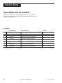
Software Set Up
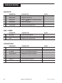
SOFTWARE SET UP CHARTS
Record the values for the various Set Up parameters in this section.
You may want to photocopy these pages instead of entering the values
on the master sheets.
CONFIG.
PARAMETER
DESCRIPTION
1
INDICATOR
Enables indicator and/or 2nd input
2
2ND INPUT
Chooses type of 2nd input
3
LINE FREQ
Chooses power source frequency
4
OUTPUT 1
Defines function of 1st output
5
CONTACT 1
Operation of 1st digital input
6
CONTACT 2
Operation of 2nd digital input
7
CONTACT 3
Operation of 3rd digital input
8
STN.NAME
Message for naming the station
36
Chapter 5, Software Set Up
VALUE
532 User’s Manual
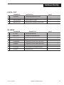
Software Set Up
LOCAL OUT.
PARAMETER
DESCRIPTION
1
LOW LIMIT
Lowest adjustable output value
2
HIGH.LIMIT
Highest adjustable output value
3
PWR.UP:MODE
Selects power-up mode
4
PWR. UP: OUT
Selects power-up output in local mode
VALUE
PV INPUT
PARAMETER
DESCRIPTION
1
PV TYPE
Sensor type selection
2
DEG. F/C/K
Temperature engineering unit
3
DECIMAL
Decimal point position
4
LINEARIZE
Type of input linearization
5
LOW RANGE
Engineering unit for lowest input value
6
HI RANGE
Engineering unit for highest input value
7
FILTER
Setting for the low pass input filter
8
PV OFFSET
Offset to the PV in engineering units
9
PV GAIN
Gain to the PV
532 User’s Manual
Chapter 5, Software Set Up
VALUE
37
Software Set Up
CUST. LINR.
PARAMETER
DESCRIPTION
1
1ST. INPUT
Input signal corresponding to 1st point
2
1ST. PV
Eng.unit value corresponding to 1st point
3
2ND. INPUT
Input signal corresponding to 2nd point
4
2ND. PV
Eng.unit value corresponding to 2nd point
5
3RD. INPUT
Input signal corresponding to 3rd point
6
3RD. PV
Eng.unit value corresponding to 3rd point
7
4TH. INPUT
Input signal corresponding to 4th point
8
4TH. PV
Eng.unit value corresponding to 4th point
9
5TH. INPUT
Input signal corresponding to 5th point
10
5TH. PV
Eng.unit value corresponding to 5th point
11
6TH. INPUT
Input signal corresponding to 6th point
12
6TH. PV
Eng.unit value corresponding to 6th point
13
7TH. INPUT
Input signal corresponding to 7th point
14
7TH. PV
Eng.unit value corresponding to 7th point
15
8TH. INPUT
Input signal corresponding to 8th point
16
8TH. PV
Eng.unit value corresponding to 8thpoint
17
9TH. INPUT
Input signal corresponding to 9th point
18
9TH. PV
Eng.unit value corresponding to 9th point
19
10TH. INPT.
Input signal corresponding to 10th point
20
10TH. PV
Eng.unit value corresponding to 10th point
21
11TH. INPT.
Input signal corresponding to 11th point
22
11TH. PV
Eng.unit value corresponding to 11th point
23
12TH. INPT.
Input signal corresponding to 12th point
24
12TH. PV
Eng.unit value corresponding to 12th point
25
13TH. INPT.
Input signal corresponding to 13th point
26
13TH. PV
Eng.unit value corresponding to 13th point
27
14TH. INPT.
Input signal corresponding to 14th point
28
14TH. PV
Eng.unit value corresponding to 14th point
29
15TH. INPT.
Input signal corresponding to 15th point
30
15TH. PV
Eng.unit value corresponding to 15th point
38
Chapter 5, Software Set Up
VALUE
532 User’s Manual
Software Set Up
SP INPUT
PARAMETER
DESCRIPTION
1
SP TYPE
Type of input signal for setpoint indicator
2
SP LOW
Eng. unit value for lowest SP input value
3
SP HIGH
Eng. unit value for highest SP input value
4
SP DISPLAY
How to display SP (SP or deviation from PV)
VALUE
VP INPUT
PARAMETER
DESCRIPTION
1
VP TYPE
Type of input signal for VP indicator
2
VP LOW
Eng. unit value for lowest VP input value
3
VP HIGH
Eng. unit value for highest VP input value
VALUE
ALARMS
PARAMETER
DESCRIPTION
1
ALM. TYPE:1
Type of alarm for alarm 1
2
ALARM SP:1
Alarm 1 setpoint
3
DEADBAND:1
Deadband for alarm 1
4
RELAY:1
State of the relay for alarm 1
5
LATCHING:1
Latching sequence of alarm 1
6
ACK. :1
Whether alarm 1 may be acknowledged
7
POWER UP:1
Treatment of alarm 1 upon power up
8
MESSAGE:1
Message for alarm 1
9
ALM. TYPE:2
Type of alarm for alarm 2
10
ALARM SP:2
Alarm 2 setpoint
11
DEADBAND:2
Deadband for alarm 2
12
LATCHING:2
Latching sequence of alarm 2
13
RELAY:2
State of the relay for alarm 2
14
ACK. :2
Whether alarm 2 may be acknowledged
15
POWER UP:2
Treatment of alarm 2 upon power up
16
MESSAGE:2
Message for alarm 2
17
RATE TIME
Time that determines rate-of-change alarm
532 User’s Manual
Chapter 5, Software Set Up
VALUE
39
Software Set Up
SECURITY
PARAMETER
DESCRIPTION
VALUE
1
SEC. CODE
Security code to temporarily unlock station
2
REM./LOCAL
Lockout of LOCAL key
3
LOCAL OUT
Lockout of /
4
ALARM ACK.
Lockout of ACK key
5
OPERATION
Lockout of OPERATIONS parameters
6
CONFIGURE
Lockout of CONFIGURATION
keys (no changes to output)
SER. COMM.
PARAMETER
DESCRIPTION
1
STATION
The unit's station address
2
BAUD RATE
The baud rate
3
CRC
Whether to calculate the CRC
VALUE
OPERATIONS
PARAMETER
DESCRIPTION
1
HOST. BREAK
Output choice if host CV signal is lost
2
R/L XFER
R-to-L transfer output change type
3
R/L RAMP
R-to-L transfer output change time
4
HOST. RESTR.
Mode when CV signal is restored
5
L/R XFER
L-to-R transfer output change type
6
L/R RAMP
L-to-R transfer output change time
7
PRESET 1
Output value for 1st preset
8
PRESET 2
Output value for 2nd preset
40
Chapter 5, Software Set Up
VALUE
532 User’s Manual
Applications
CHAPTER 6
APPLICATIONS
The 532 has a variety of user-programmable control features and capabilities. This chapter describes their applications.
532 Auto/Manual Station ................................................................... 41
Alarm Set Up ...................................................................................... 42
Digital Inputs ...................................................................................... 47
Process Variable, Setpoint and Valve Position Indication ............. 48
Input Linearization ............................................................................. 49
Ramp to Control Value ...................................................................... 52
Security ............................................................................................... 52
Process Variable Reading Correction ............................................. 53
Serial Communications ..................................................................... 54
NOTE:
Available capabilities depend upon the
hardware option you specified and
ordered.
NOTE:
In this chapter, the
abbreviations are used:
CV - Control signal
SP - Set point
VP - Valve Position
PV - Process Variable
532 Auto/Manual Station
following
The 532 Auto/Manual Station provides automatic and manual control backup
for critical control loops. It is normally installed between a Host device and
the final control element. The Host may be a PLC, DCS or single loop
controller (SLC). The final control element may be a valve actuator, positioning device, power control unit for an electric heating element, pump or other
control device. The control signal must always be a 4-20mA proportional
signal.
A. HOST Mode (Default Mode)
1. In the Host mode, the 532 is transparent to the control loop; it
passes the control signal from the Host device without any degradation.
2. The 532 constantly monitors the CV and uses the last good signal
as a potential CV for the transition mode.
3. In Host mode, the 532 can be removed from the case without
disrupting the Host signal; it is not a point of failure.
B. Transition Mode to LOCAL
1. The 532 switches to Local mode due to:
a. Loss of the Host signal
b. Keypad selection
c. Closure of a digital contact; or
d. Commands through the RS-485 port.
2. Upon switching to Local, the 532 generates a control signal based
on the last known CV from the Host, or selects one of two
predetermined CV(s).
532 User’s Manual
DISPLAY
Next Parameter
MENU
Next Block
FAST
+
Chapter 6, Applications
MENU
Next value
▲
or
▲
Escape to Operation Mode
41
Applications
3. The 532 can ramp the last Host signal value to either of the
predetermined CV value(s).
4. In Local mode, the operator can modify the CV signal using
keys.
C. Transition Mode to HOST Mode
and
1. The 532 returns to Host Mode due to:
a. Return of Host signal (if configured to do so);
b. Keypad selection;
c. Digital contact; or
d. Commands through the RS-485 port.
2. Upon return of the Host signal, the 532 can be programmed to
a. Return control to the Host immediately;
b. Ramp to the new CV at a predetermined rate; or
c. Remain in Local mode. In Local mode, the operator can
determine whether or not the Host signal is valid.
Alarm Set Up
The 532 has 2 available alarms. It indicates alarm conditions by:
•
•
•
Lighting up the alarm icon(s).
Displaying a custom message in the 3rd display
Illuminating the ACK key if the alarm is acknowledgeable.
On the 532, you assign one of 6 different types to each alarm. Also, by adding
an output module, one of the alarms can be tied a relay output.
A. Set the Alarm Type.
NOTE:
Refer to Chapter 4 for information on
wiring for alarms.
NOTE:
Refer to Chapter 2 for information on
operating alarms.
1. Press FAST + MENU to toggle to the ALARM menu.
2. Press MENU to select the first parameter ALM.TYPE:1 and select its
type (choose one of the following) using the
and
keys:
LOCAL
If tied to a relay output, a Local alarm notifies the Host that the 532
has taken over manual control. You can choose LOCAL for only one
of the 532 alarms. This alarm is useful when the Host performs logging functions for Statistical Process Control (SPC), or to prevent reset
windup.
HIGH ALRM.
The high process variable alarm occurs when the process variable
exceeds the alarm setpoint.
LOW ALARM
The low process variable alarm occurs when the process variable goes
below the alarm setpoint.
42
DISPLAY
Next Parameter
MENU
Next Block
Chapter 6, Applications
FAST
+
MENU
Next value
▲
or
▲
Escape to Operation Mode
532 User’s Manual
Applications
BAND
The band alarm creates a band twice the size of the alarm setpoint
[centered] around the control setpoint. An alarm occurs when the
process variable travels outside of this band. For example, if your
control setpoint is 500 and the band alarm setting is 25, the alarm
occurs if the PV travels outside of the 475 to 525 range.
This alarm is dependent upon retransmission of the control setpoint
to the 532. As the control setpoint changes, the band changes accordingly.
DEVIATION
The deviation alarm creates a band on one side of the control setpoint. An alarm occurs when the process variable deviates from the
control setpoint by an amount greater than the alarm setpoint.
For example, if the control setpoint is 500 and the alarm setpoint is
+50 (plus 50), an alarm occurs when the process variable exceeds
550. If your alarm setpoint is –50, the alarm occurs when the process variable drops below 450.
This alarm is dependent upon retransmission of the control setpoint
to the 532. As the control setpoint changes, the band changes accordingly.
NOTE:
The Band and Deviation alarms are
not selectable without a PV and a
retransmitted SP signal.
RATE
The rate alarm occurs when the process variable changes at a rate
greater than that specified by the alarm setpoint and time base. For
example, if you have an alarm setpoint of 10 and a time base of 5
seconds, an alarm occurs if the VP changes greater than 10 in 5
seconds.
Use RATE to signal an alarm before the PV reaches an undesirable
level.
3. Press the MENU key to select the second parameter ALM.TYPE:2 and
select its type using the
and
keys.
B. Set the Alarm Parameters
Each alarm type (except the 532 LOCAL alarm) has a number of corresponding parameters that must also be set up in the ALARM menu.
Smart Menus feature: only those parameters that apply to your particular
alarm type will appear as you toggle through the parameters.
Press the MENU key to select the rest of the parameters in the ALARM menu,
and choose their values with the
and
keys.
4. ALARM SP:1 and ALARM SP:2
Specifies, in engineering units, the point at which the alarm occurs.
For a rate-of-change alarm, it specifies the amount of change that must
occur before the alarm activates. A negative value specifies a negative
rate-of-change.
532 User’s Manual
DISPLAY
Next Parameter
MENU
Next Block
FAST
+
Chapter 6, Applications
MENU
Next value
▲
or
▲
Escape to Operation Mode
43
Applications
5. DEADBAND:1 and DEADBAND:2
Specifies the range through which the PV must travel before leaving an
alarm condition (see alarm examples at the end of this section).
This prevents frequent alarm oscillation or “chattering” if the process
variable has stabilized around the alarm point.
6. RELAY:1 and RELAY:2
Specifies whether the relay will be on or off. ON means the relay is
energized, while OFF means the relay is de-energized when the station
is in the alarm condition.
Most applications require the relay to energize. However, limit applications usually require the relay to de-energize.
7. LATCHING:1 and LATCHING:2
If the alarm is latching (YES), the alarm remains active after leaving the
alarm condition unless acknowledged.
If the alarm is non-latching (NO) the alarm returns to its non-alarm state
when leaving the alarm condition without being acknowledged.
8. ACK.:1 and ACK.:2
NOTE:
You can specify whether the relay is
Normally Open or Normally Closed
when configuring the hardware, with
jumper selection for outputs 1, 2 & 3.
ENABLED allows the operator to acknowledge an alarm at any time, even
if the control process is still in the alarm condition.
DISABLED prevents the operator from acknowledging an alarm while the
process is in the alarm condition.
When either alarm is available to be acknowledged, the ACK key will be
illuminated. If both alarms are acknowledgeable, press the ACK key once
to acknowledge alarm #1, then a second time for alarm #2. A latching
alarm can always be acknowledged when it is out of the alarm condition.
9. POWER UP:1 and POWER UP:2
If you want the controller to always power up in alarm, regardless of the
alarm condition, then select ALARM. This is an excellent way to activate
an alarm if there has been a power failure.
If you never want the controller to power up in alarm, regardless of alarm
condition, select DELAYED. The system must leave and reenter the
alarm condition before the alarm will activate. This is typically used to
avoid alarms during start up.
If you want the system to power up in alarm only if it is in an alarm
condition, select NORMAL.
10. MESSAGE:1 and MESSAGE:2
Allows you to enter a nine character message to display when the
respective alarm is active. The first character of the 3rd display will be
and
keys to scroll through character set for each
flashing. Use
character Press FAST to enter the selection and move to next digit.
Press MENU to advance to next parameter.
44
DISPLAY
Next Parameter
MENU
Next Block
Chapter 6, Applications
FAST
+
MENU
Next value
▲
or
▲
Escape to Operation Mode
532 User’s Manual
Applications
11. RATE TIME
Defines the time period over which a specific change in process variable
must occur for the rate alarm to be activated. The amount of change is
defined by the alarm setpoint. The rate-of-change is defined as the
amount of change divided by the time period. In general, for a given rateof-change, the shorter the time period, the more sensitive the rate alarm.
Example:
a. If the alarm setpoint is set to 10 and the time base is set to 1
second, the rate of change is 10 units per second. The process
variable would only have to experience a ten unit change over a
short period of time.
b. If the alarm setpoint is set to 100 and the time base set to 10, the
rate of change is also 10 units per second. The PV would require
a 100 unit change over a ten second period.
Notice that Example A is more sensitive than Example B.
For graphic examples of alarm applications, see next page.
532 User’s Manual
DISPLAY
Next Parameter
MENU
Next Block
FAST
+
Chapter 6, Applications
MENU
Next value
▲
or
▲
Escape to Operation Mode
45
Applications
Figure 6.1
Alarm Examples
Alarm Examples
A.SP - Alarm Setpoint C.SP = Control Setpoint
DB = DeadbandPV = Process Variable
BAND ALARM
HIGH PROCESS VARIABLE ALARM
IN ALARM
CONDITION
IN ALARM
CONDITION
IN ALARM
CONDITION
C.SP + A.SP
DB
PV
PV
A.SP
DB
C.SP
DB
TIME
C.SP – A.SP
TIME
RELAY
RELAY
ENERGIZED DE-ENERGIZED
RELAY
ENERGIZED
RELAY
DE-ENERGIZED
ICON OFF
ICON ON
ICON OFF
ICON ON
NO ALARM
CANNOT
NO ALARM
ACKNOWLEDGE
RELAY
DE-ENERGIZED
RELAY
ENERGIZED
RELAY
DE-ENERGIZED
ICON OFF
ICON ON
ICON OFF
NO ALARM
MAY
ACKNOWLEDGE
NO ALARM
CANNOT
ACKNOWLEDGE
PARAMETER SETTINGS:
PARAMETER SETTINGS:
ALM. TYPE:1 = BAND
RELAY:1 = RELAY OFF
ALM. TYPE:1 = HIGH ALRM.
RELAY:1 = RELAY ON
LATCHING = NO LATCH
ACK.:1 = DISABLED
DEVIATION ALARM
POWER UP ALARM
PV
IN ALARM
CONDITION
C.SP
LATCHING = NO LATCH
ACK.:1 = ENABLED
A.SP
DB
DB
C.SP + A.SP
PV
RELAY
ENERGIZED
ICON OFF
ICON ON
NO ALARM
MAY
ACKNOWLEDGE
MUST
ACKNOWLEDGE
TO SHUT OFF
ICON AND
DE-ENERGIZE RELAY
PARAMETER SETTINGS:
ALM. TYPE:1 = DEVIATION
RELAY:1 = RELAY ON
Escape to Operation Mode
46
TIME
RELAY
ENERGIZED
RELAY
ENERGIZED
RELAY
ENERGIZED
ICON ON
ICON ON
ICON ON
MAY
ACKNOWLEDGE
CANNOT
ACKNOWLEDGE
MAY
ACKNOWLEDGE
PARAMETER SETTINGS:
LATCHING:1 = LATCH
ACK.1 = ENABLED
DISPLAY
ALARM SP:1 = ( < 0)
Next Parameter
MENU
ALM. TYPE:1 = HIGH ALM.
RELAY:1 = RELAY ON
Next Block
Chapter 6, Applications
FAST
+
LATCHING:1 = LATCH
ACK.:1 = DISABLED
MENU
Next value
POWER UP:1 = ALARM
▲
or
▲
RELAY
DE-ENERGIZED
ALARM
CONDITION
UNIT
POWER UP
TIME
532 User’s Manual
Applications
Digital Inputs
This optional feature is only available if ordered originally from the factory.
For a set of 3 digital inputs can be ordered, order Product #532 -xxxxxxDx00.
If more than one digital input is closed, then the last one closed generally has
priority over the others.
A closed digital input may be overridden by: another digital input, a keyboard
operation, or an automatic function. A closed digital input that was overridden
must be opened, in order to be “rearmed”.
If one digital input is closed and selects the LOCAL, and then REMOTE is
keyboard selected, the keyboard selection takes precedence.
1. Press FAST + MENU to toggle to the CONFIG. menu.
2. Press MENU to access first parameter, CONTACT:1. Use
and
toggle to the desired function (choose one of the following):
ALARM ACK.
to
Upon contact closure, all active alarms are acknowledged. The digital input must be opened before it is “rearmed”. If the input remains
closed, it does not continue to immediately acknowledge alarms as
they become active.
UP KEY and DOWN KEY
Contact closure mimics the and keys. If the station is mounted
behind a window, this digital input allows you to use momentary
contact push button to change the station’s output.
COMM. ONLY
Renders digital input status readable through communications. It will
have no effect on the functions of the station itself.
LOCAL.LAST
Upon contact closure the station switches to Local mode and uses
the last good control value (CV) from the Host as its output.
LOCAL.PRE1
Upon contact closure the station switches to local mode and uses
preset output value #1 as the output control value.
LOCAL.PRE2
Upon contact closure the station switches to local mode and uses
preset output value #2 as the output control value.
OUT LOCK
Upon contact closure the station switches uses the LOCKED OUT.
value as the CV and prevents changing it from the keypad.
3. Press MENU to access second and third parameters, CONTACT:2 and
CONTACT:3. Use the
and
keys to toggle to the desired function
for these as well (choose one of the following).
532 User’s Manual
DISPLAY
Next Parameter
MENU
Next Block
FAST
+
Chapter 6, Applications
MENU
Next value
▲
or
▲
Escape to Operation Mode
47
Applications
Process Variable, Setpoint and Valve Position
Indication
The 532 can be set up to display the process variable. This can be a direct
input of a thermocouple, RTD, mA or voltage signal. Milliamp and voltage
signal can be displayed as 0-100% or scaled in Engineering units. Custom
linearization is also available.
A. Choose the Type of Display(s)
You need to define what indicators you want to display: NONE, the PV, the
SP, the VP, the PV and the SP or the PV and the VP.
Because the 532 can show two values at once, the operator has complete
information concerning the Host device; this eliminates the need for other
indicators. By tying these features to the 532 alarm capability, the operator
may establish alarms independent of the Host system.
1. Press FAST + MENU to toggle to the CONFIG. menu.
2. Press MENU to access the INDICATOR parameter. Use
and
to
choose the indicator display: NONE, PV, 2ND (activated 2nd second
input) or PV/2ND (both PV and 2ND input).
3. Press MENU to access the 2ND INPUT parameter. Use
choose the 2ND type of indicator display: VP or SP.
and
to
See Chapter 2 for information about displaying and adjusting the CV.
B. Select the Process Variable Display Range
1. Press the FAST + MENU keys to toggle to the PV INPUT menu. Press
MENU to access the following parameters, and use the and keys
to assign values.
2. PV TYPE
Defines the range of the input signal (T/C, RTD, mA or voltage signal).
The type of signal is governed by the hardware jumper selections (see
Chapter 3).
3. DEG. F/C/K
Selects the units for temperature display (appears only for T/C and RTD
input types).
4. DECIMAL
Sets the position of the decimal point (appears only for V/mA and RTD
input types).
5. LINEARIZE
Selects the type of PV linearization being used (appears only for V/mA
input types).
6. LOW RANGE
NOTE:
Please see Chapter 3 or proper jumper
settings for the PV and SP/VP.
Sets the value in engineering units corresponding to the low PV input
value (appears only for v/mA input types).
48
DISPLAY
Next Parameter
MENU
Next Block
Chapter 6, Applications
FAST
+
MENU
Next value
▲
or
▲
Escape to Operation Mode
532 User’s Manual
Applications
7. HI RANGE
Sets the value in engineering units corresponding to the high PV input
value (appears only for V/mA inputs types).
8. FILTER
Sets the amount of PV filtering to be used.
9. PV OFFSET
Sets a constant offset to be applied to the PV input.
10. PV GAIN
Sets a constant gain to be applied to the PV input (appears only for V/
mA input types).
C. Set Point Display Range
The 532 can be set up to display a retransmitted setpoint from the HOST
device. This is a powerful feature when the PV indicator option is also used.
1. Press FAST + MENU to toggle to the SP INPUT menu. Press MENU to
access the following parameters, and use
and
to assign values.
2. SP TYPE
Defines the input signal range. ( 0 - 20mA or 4 - 20mA).
3. SP LOW and SP HIGH
These define the range of the set point in engineering units. The correct
range will be dependent on the source of the set point signal.
4. SP.DISPLAY
Selects whether to display SP as an actual SP (SET POINT) or as a
deviation from PV (DEVIATION). This function appears only if both PV
and SP indicators are enabled.
D. Valve Position Display Range
The 532 can be set up to display a retransmitted valve position from the
HOST device.
1. Press FAST + MENU to toggle to the VP INPUT menu. Press MENU to
access the following parameters, and use
and
to assign values.
2. VP TYPE
Defines the input signal range. ( 0 - 20mA or 4 - 20mA).
3. VP LOW and VP HIGH
These define the range of the valve position in engineering units. The
correct range will be dependent on the source of the set point signal.
Input Linearization
A. Thermocouple and RTD Linearization
When you select a thermocouple or RTD input, the station automatically
linearizes the incoming signal. The station uses internal lookup tables to
provide an accurate reading of the temperature being sensed.
532 User’s Manual
DISPLAY
Next Parameter
MENU
Next Block
FAST
+
Chapter 6, Applications
MENU
Next value
▲
or
▲
Escape to Operation Mode
49
Applications
B. Square Root Linearization
Many flow transmitters generate a nonlinear signal corresponding to the flow
being measured. The station must have the square root of this signal in order
to use it. The station has the capability to perform this function for itself.
To utilize this feature, you must have a voltage or milliamp input.
1. Press FAST + MENU to toggle to the PV INPUT menu.
2. Press MENU to access the LINEARIZE parameters, and use the and
keys to assign value SQR. ROOT.
For the first 1% of the input span, the input is treated in a linear fashion. After
that, it is a value calculated using the formula in Figure 6.2:
PV = Low Range + [ (Hi Range – Low Range)
Where:
(V input - V low / (V high – V low) ]
Figure 6.2
Square Root Linearization Formula
Hi Range is the high end of the process variable.
Low Range is the low end of the process variable.
V input is the actual voltage or current value of the input.
V high is the high end of the input signal range (e.g. 5 volts or 20 mA).
V low is the low end of the input signal range (e.g. 1 volt or 4 mA).
Example: Process variable range is 0 – 1000.
Input signal range is 1–5 volts
Input signal is 3 volts.
Therefore, the PV will be—
PV = 0 + [(1000 – 0) (3-1) / (5–1) ] = 1000 .5 = 707
C. Custom Linearization
Custom linearization allows you to take virtually any nonlinear signal and
linearize it using a 15-point straight line approximation curve (see Figure 6.3).
Typical applications are linearizing signals from nonlinear transducers, or
controlling volume based on level readings for irregularly-shaped vessels. To
define the function, you must enter data point pairs—the engineering units
corresponding to a particular voltage or current input.
50
DISPLAY
Next Parameter
MENU
Next Block
Chapter 6, Applications
FAST
+
MENU
Next value
▲
or
▲
Escape to Operation Mode
532 User’s Manual
Applications
15th
PV
Figure 6.3
Custom Linearization Curve
PV VALUE
(IN ENGINEERING 10th
PV
UNITS)
5th
PV
NOTE:
The resulting linearization curve must
be either ever-increasing or everdecreasing.
1st
PV 1st
Input
5th
Input
15th
Input
10th
Input
INPUT VALUE
(IN MILLIAMPS OR VOLTAGE)
1. Press FAST + MENU to toggle to the INPUT menu.
2. Press MENU to access the LINEARIZE parameters, and use the
keys to assign value CUSTOM.
3. Press FAST + MENU to toggle to the CUST.LINR. menu.
and
4. The parameter 1ST INPUT is fixed at the low end of the mA or Voltage
input range.
Escape to Operation Mode
532 User’s Manual
DISPLAY
5. For parameter 1ST PV, define the corresponding process variable
value in engineering units.
6. For 2ND INPUT, 3RD INPUT…15TH INPUT, define the milliamp or
voltage input of the corresponding data point.
7. For the 2ND PV, 3RD PV…15TH PV, define the corresponding process
variable value in engineering units.
Once the various points are defined, the station interpolates the values
between the points using a straight line relationship between them.
Next Parameter
MENU
Next Block
FAST
+
Chapter 6, Applications
MENU
Next value
▲
or
▲
NOTE:
If you make any modifications to a set
curve, you must re-enter all points in
order, from 1 to X. Use the Set Up
Charts in Chapter 5 to record your data.
51
Applications
Ramp to Control Value
The “ramp to control value” function is especially useful in processes where
the rate-of-change (from Remote to Local, or Local to Remote) of the control
value must be limited, or under any circumstances where there is likely to be
a significant difference between control values at mode transition time.
Under normal operating circumstances, the 532 passes the Host device
signal to the final control element without modification, and stores the current
CV value with each cycle of the CPU. When the 532 switches to Local mode
(see page 2 for details), it will provide a CV based on the last known good
value from the Host . It can also, however, go to one of two preset outputs.
These values may be considerably different from the Host value, so a sudden
change in the output value is possible. The ramp feature enables the operator
to select how long it will take the output to change from one value to the other.
The 532 has provisions for ramping from Remote to Local, and from Local
to Remote.
1. Press the FAST + MENU keys to toggle to the OPERATIONS menu.
2. For Remote to Local mode transfer, set the parameter R/L XFER
(remote to local transfer type), to type RAMP.
2. For Local to Remote mode transfer, set the parameter L/R XFER (local
to remote transfer type) to type RAMP.
3. Either the R/L RAMP (remote to local ramp) parameter and/or
L/R RAMP (local to remote ramp) will now be available. Enter the
transition time (5-120 seconds).
When this function is active the controller will automatically ramp the control
value at the desired rate during the transition from remote to local control or
local to remote control. It will also work if preset values have been chosen
when transferring between remote and local control.
Security
The security function contains parameters that allow the user to selectively
lock out the various functions of the station. Security only locks out the
keypad commands. Digital Inputs or Serial Communications are not affected.
1. Press the FAST + MENU keys to toggle to the SECURITY menu. Press
MENU to access each of the following parameters, and the
and
keys to set their values.
2. SEC. CODE
Selects whether the LOCAL key should be LOCKED or UNLOCKED. This
function would prevent the operator from placing the 532 in Local mode.
Transfer to Local mode is accomplished by loss of Host signal, digital
contact closure or Serial Communications only.
Escape to Operation Mode
52
DISPLAY
Next Parameter
MENU
Next Block
Chapter 6, Applications
FAST
+
NOTE:
Be sure to set the SEC. CODE before
locking any other feature. The station
will not display this parameter if any
others have been LOCKED. You
would have to unlock all other
parameters in order to view the
SEC. CODE again.
MENU
Next value
▲
or
▲
Define the security code using the and keys. This parameter does
not appear unless all functions are unlocked. The security function is
compromised if the security code is left at zero (0).
3. REMOT./LOCL
532 User’s Manual
Applications
4. LOCAL OUT
Selects whether the raise and lower keys should be LOCKED or
UNLOCKED in Local mode. This selection prevents the operator from
changing the output value when in Local mode.
5. ALARM ACK.
Selects whether the ACK key should be LOCKED (to prevent an operator
from acknowledging any alarms) or UNLOCKED.
6. OPERATION
Selects whether the operation menu should be LOCKED or UNLOCKED.
This selection prevents the operator from accessing the OPERATION
menu.
7. CONFIGURE
When LOCKED, allows access to the configuration menus, but prevents
any unauthorized changes to the configuration parameters. You must lock
CONFIGURE if you want full security. If left UNLOCKED, the operator has
access to the security code.
Whenever a locked function is attempted, the operator has the opportunity to
enter a security code to override the Lock. If the correct code is entered, the
operator has full access. The security feature reactivates after one minute of
keypad inactivity.
The operator also can enter the SECURITY OVERRIDE CODE, which, if
entered correctly, RESETS the whole station to its default settings.
The security override code is
62647 . Store this in a secure place.
Process Variable Reading Correction
NOTE:
The Process Variable Reading
Correction feature is provided as a
convenience. We recommend that the
condition causing the erroneous
reading be corrected.
Under certain extraneous conditions—such as an aging thermocouple, out of
calibration transmitter, lead wire resistance—the station may display values
other than the actual process value. To compensate for these conditions, you
can set offset and gain values for the process variable.
1. Press FAST + MENU to toggle to the PV INPUT menu. Press MENU to
access each of the following parameters, and the
and
keys to set
values for them.
2. PV OFFSET
This either adds or subtracts a set value from the process variable
reading in engineering units. For example, if your thermocouple was
always reading 3° too high, you could set the PV OFFSET parameter to
-3 to compensate.
Escape to Operation Mode
532 User’s Manual
DISPLAY
3. PV GAIN
Multiplies the deviation from the low end of the process variable range by
the gain factor and then adds it to the value of the low end of the range
to arrive at the adjusted process variable value.
Next Parameter
MENU
Next Block
FAST
+
Chapter 6, Applications
MENU
Next value
▲
or
▲
NOTE:
PV GAIN is only available if using a linear
voltage or current input.
53
Applications
Example:
If your process variable range is 50 to 650 and the process variable
reading is 472, a PV GAIN of 0.995 would yield an adjusted process
variable equal to [(472 – 50) x.995] + 50 = 470.
By using a combination of both offset and gain factors, you should be able
to compensate for just about any inaccuracy in your sensor or transmitter.
Serial Communications
Serial communications is an optional feature. It enables the station to
communicate with a supervisory device, such as a personal computer or
programmable logic controller. The circuitry for communications is contained
on a modular circuit board that plugs into the Microcontroller Circuit Board.
The station uses communications standard RS-485, which provides a multidrop system that communicates at a high rate over long distances. Typical
limitations are 32 stations per pair of wires over a distance up to 4000 feet.
The station uses a proprietary protocol which provides an extremely fast and
accurate response to any command. A Cyclic Redundancy Checksum (CRC)
can be enabled to ensure the integrity of any data read by the controller.
Through communications, you have access to every set up and operating
parameter in the station.
NOTE:
For further details on the station’s
communications protocol, contact one
of our application engineers.
1. Press the FAST + MENU keys to toggle to the SER.COMM. menu. Press
MENU to access each of the following parameters, and use the
and
keys to set values for them.
2. STATION
Specifies the unit’s station address. It is the only way one controller can
be distinguished from another. Each controller on the same
RS-485 interface must have a unique station address.
3. BAUD RATE
Choose a baud rate from 1200 to 19,200. In general, you want to select
the highest baud rate. However, every station on the RS-485 interface
must be set to the same baud rate.
4. CRC
Indicates if you are going to take advantage of the Cyclic Redundancy
Checksum feature. If your Host program supports it, we highly recommend that you activate it.
54
DISPLAY
Next Parameter
MENU
Next Block
Chapter 6, Applications
FAST
+
MENU
Next value
▲
or
▲
Escape to Operation Mode
532 User’s Manual
Flowcharts
APPENDIX A
MENU & PARAMETER FLOWCHARTS
OPERATING
OPERATIONS
HOST.BREAK
R/L XFER
PRESET 1
PRESET 2
INDICATOR
2ND INPUT
CONTACT 3
STN. NAME
LOCAL.OUT
LOW LIMIT
HIGH.LIMIT
PV INPUT
PV TYPE
DEG. F/C/K
DECIMAL
FILTER
PV OFFSET
PV GAIN
CUST. LINR.
1ST. INPUT
1ST. PV
SP INPUT
SP TYPE
VP INPUT
ALARMS
R/L RAMP
HOST.RESTR.
LINE FREQ.
OUTPUT:1
L/R XFER
L/R RAMP
CONTACT 1
CONTACT 2
SET UP
CONFIG.
532 User’s Manual
PWR.UP:MODE PWR.UP:OUT
LOCKED.OUT
LINEARIZE
LOW RANGE
HI RANGE
2ND. INPUT
2ND. PV
15TH. INPUT*
15TH. PV*
SP LOW
SP HIGH
SP DISPLAY
VP TYPE
VP LOW
VP HIGH
ALM. TYPE:1
ALARM SP:1
DEADBAND:1
RELAY:1
LATCHING:1
ACK.:1
POWER UP:1
MESSAGE:1
ALM. TYPE:2
ALARM SP:2
DEADBAND:2
RELAY:2
LATCHING:2
ACK.:2
POWER UP:2
MESSAGE:2
RATE TIME
SECURITY
SEC. CODE
REM./LOCAL
LCOAL OUT
ALARM ACK.
OPERATION
SER. COMM.
STATION
BAUD RATE
CRC
Appendix A, Menu & Parameter Flowcharts
CONFIGURE
A-1
Parts List
APPENDIX B
PARTS LIST
CIRCUIT
BOARD SUPPORT
(BEZEL INSERT)
MOUNTING BRACKET
(BEZEL INSERT)
GASKET
OPERATOR
INTERFACE ASSEMBLY
TERMINAL BLOCK*
*Terminal Circuit
Board Not Shown
CIRCUIT BOARDS
Description
Part #
Description
Part #
Mechanical relay module
535 600
Mounting kit
(including mounting brackets and screws)
535 661
532 Analog (mA) module
532 600
Bezel retention screw kit
535 663
Solid State Relay (triac) Module
535 602
DC Logic (solid state relay drive) module
535 603
Module retention kit
(w/retention plate & tie wrap for outputs 1-3)
535 664
Loop Power Module
535 604
RS-485 serial communications board
535 605
OUTPUT MODULES
REPAIR PARTS
Operator interface assembly 532
532 632
Power supply circuit board
535 630
Microcontroller circuit board 532
535 632
Option circuit board
535 620
Option circuit board w/3 digital inputs 532
532 621
EPROM 532
532 640
Lithium battery
093 128
Jumper kit (set of all jumper connectors)
535 660
Gasket kit (w/panel and bezel gaskets)
535 662
532 User’s Manual
Module retention tie wrap kit
(set of 5 tie wraps)
535 665
Terminal block
535 031A
Circuit board support (Bezel Insert)
535 025
Sheet of engineering unit labels
535 106
532 Bypass board
532 100
Goof Plate
512 014
Appendix B, Parts List
B-1
Troubleshooting
APPENDIX C
TROUBLESHOOTING
Message
When does it occur?
DEFAULTS
Whenever the memory is cleared and all
parameters revert to factory default
settings. This may be done by purposely
clearing the memory or when the unit is
powered up for the first time or if the
software version is changed.
Changing any Set Up parameter will
clear the message. If due to something other than the user purposely
clearing the memory, call factory for
assistance.
NEEDS CAL.
Indicates that calibration values are at
factory defaults.
Recalibrate the unit
LOST CAL
Indicates that the calibration data has
been lost. Occurs when the memory is
wiped clean.
Problem should never occur. Must
correct the problem, then recalibrate.
Call factory for assistance.
ERROR:ROM
CHECKSUM
On power up a problem with the ROM is
detected. This is a fatal error and requires
an EPROM change. Controller locks up
until fixed.
Call factory for assistance.
OUT1/CONF
Upon power up, controller senses that the
modules needed for control as determined by software configuration are not
present.
Must power down and install correct
module combination or must
reconfigure the controller to match the
current module combination.
If the cold junction is sensed to be lost.
Call factory for assistance.
LOST CJC
532 User’s Manual
Appendix C, Troubleshooting
What to do:
C-1
Troubleshooting
SYMPTOM
Display will not light up
Improper/Lost PV reading
• Voltage/current
Improper/Lost PV reading
• Thermocouple
Improper/Lost PV reading
• RTD
No control output
PROBLEM
SOLUTION
Defective power source
Improper wiring
Check power source and wiring
Correct wiring
Blown in-line fuse
Unit not inserted in case properly; or,
Check wiring, replace fuse
Remove unit from case (and remove
screws have not been tightened.
bezel screws), then reinsert unit and
properly tighten screws.
Input jumper selection improperly set
Input range improperly selected in
Move jumper to proper location.
software
Reverse polarity
Select proper range
Check and correct sensor wiring
If station powered up, improperly wired
If internal supply for transmitter not
Check and correct wiring
installed
Defective transmitter
Install module
Replace transmitter
Transmitter signal out of range
Defective thermocouple
Select proper range in software
Replace thermocouple
Input jumper selection improperly set
Wrong TC type selected in software
Move jumper to proper location.
Select proper thermocouple type in
software
Improper wiring
Defective RTD
Wire properly
Replace RTD
Input jumper selection improperly set
Improper wiring
Move jumper to proper location.
Wire properly
Output module not installed
Output wiring and module location do not
Install proper output modules
Check and correct wiring or module
match
If SSR, SSR Drive of Milliamp output,
location
Move jumper to proper location.
jumpers J1, J2 and J3 are not set properly
Software configuration does not match
Reconfigure software to match
hardware (OUTx CONF. message)
hardware. See OUTx CONF.
mesage.
Can't switch to Host control
Host CV signal is not connected or valid
Check wiring. Check that Host is
supplying a valid CV signal.
Erratic display
Resetting action due to electrical noise on
powerline
Filter power line.
C-2
Appendix C, Troubleshooting
532 User’s Manual
Calibration
APPENDIX D
CALIBRATION
The first three sections of this chapter provide information on calibration for:
RTD and VmA inputs, Thermocouple Cold Junction Compensation,
and Milliamp Output.
Access these parts of the calibration menu as shown in Figure D.1.
Regarding Calibration
To maintain optimum performance, once a year calibrate the analog input,
cold junction (when a thermocouple is used) and mA Out (when used). To
achieve published accuracy specifications, follow directions carefully and
use calibrated instruments of like quality to those suggested. Also, if you
move a station chassis into an alternate case or change its hardware
configuration, and you choose to use thermocouple input, you may want to
recalibrate the cold junction for optimal accuracy. Failure to do so may
result in small junction temperature (not more than 0.6°C/1.1°F).
CAL VREF
CALIBRATE
ANLG. IN
PRESS ACK
5.0000
CAL. 120mV, etc.
PRESS MENU
PRESS ACK
PRESS MENU
Figure D.1
Flowchart to Access the Calibration
Menus
PV = –150 C
CALIBRATE
PRESS ACK
PRESS ACK
COLD JUNC.
PRESS ACK
PRESS MENU
PRESS MENU
CALIBRATE
OUTPUT "X"
OUTPUT "X"
PRESS ACK
PRESS MENU
0 mA
ANLG. OUT
PRESS ACK
PRESS MENU
RESET
RESET
PUSH MENU
PRESS ACK
MENU DATA
TO RESET
After two
seconds
COMPLETED
RESET
SKIPPED
PRESS MENU
HARDWARE
SCAN
PRESS MENU
before 2 seconds
PRESS ACK
DISPLAY ONLY
PRESS MENU
532 User's Manual
Appendix D, Calibration
D-1
Calibration
Before you Begin
! The 532 comes from the factory with one milliamp output module installed
in position (output) 2 and relays in position (outputs) 3 and 4. These must
not be modified. You may install a mechanical relay, solid state relay
or DC logic module in position (output) 1 for alarm functions.
! Terminals 1 and 2 carry live power. Do not touch these terminals when
AC power is on.
RTD, VmA Input Calibration (for indication feature)
Equipment:
• Precision 5-1/2 or 6-1/2 digit multimeter, such as a Fluke 8842 ®
or Hewlett Packard HP3478A®
•
•
Two small pieces of wire
Test leads with clips
• #2 Phillips screwdriver
1. Disconnect power to the instrument.
2. Remove chassis from case.
EPROM
TB2
V
MA
V
MA
TC
TC
RTD
5-Pin Connector
Figure D.2
Microcontroller Circuit Board
Female 22-Pin Connector
Female 22-Pin Connector
PV1
2ND
BATTERY
TB1
3. Locate jumpers locations marked PV1 and 2nd near the edge connector
of the Microcontroller Circuit Board (Figure D.2). Reposition one of the
jumpers on the pins marked V of the 2nd jumper location and the other
on the pins marked TC of the 2nd jumper location.
4
WARNING!
ELECTRIC SHOCK HAZARD!
Terminals 1 and 2 carry live power. Do
not touch these terminals when AC
power is on.
D-2
4. Connect the hookup wire, as shown in Figure D.3, to terminals 31 and
32. The hook up wire connects to the multimeter. Set the meter for DC
volts. Make sure the screws are tight.
5. Reinsert chassis into the case, secure the front panel screws, and
apply power. The 2nd display should read CALIBRATE while the 3rd
display will read ANLG. IN. Allow the station and meter to warm up
for at least 45 minutes before proceeding.
6. Press the ACK key for the first step in the ANLG. IN Menu. The 2nd
Appendix D, Calibration
3
532 User’s Manual
Calibration
display will read CAL. VREF, while the 3rd display will read a value
close to 5.0000. Refer to the flowchart in Figure D.1 for guidance.
7. Your meter should read a value between 4.9750 and 5.0250. Press
and keys on the station until the 3rd display on the station matches
your meter’s reading. Note that the FAST key is active should you
decide to use it to move more quickly.
8. Press MENU . The 2nd display reads CAL. 120mV and the 3rd display
will now read a value close to 120mV. Repeat step 7.
9. Press MENU again and repeat this procedure for the remaining voltages
(90mV, 60mV, 30mV and 0mV). Each time, you should match the
displays of the station and your meter.
10. Continue to press MENU if you want to check your settings. Press ACK
when done. If you will be calibrating milliamp outputs, power down, then
up again. Wait at least 5 minutes, then continue on to Milliamp Output
Calibration, Step 5. If you are finished calibrating, power down and
place the jumpers in their correct operating positions (as specified in
Chapter 4).
11. IMPORTANT!
You must press ACK at the end of any calibration procedure to return
to the calibration menu before powering down.
17
25
18
26
19
27
20
28
21
29
22
30
23
31
–
24
32
+
hook-up wires to multi-meter
Figure D.3
RTD, VmA Calibration Wiring
Thermocouple & Cold Junction Calibration
(for indication feature)
We recommend that you always perform the input calibration before the
cold junction calibration.
Equipment:
• Precision 5-1/2 or 6-1/2 digit multimeter, such as a Fluke 8842® or
Hewlett Packard HP3478A®
• Two small pieces of wire
• Test leads with clips
• #2 Phillips screwdriver
• Precision thermocouple calibrator such as a Micromite II® by
Thermo Electric Instruments
• Type T thermocouple wire (2 pieces), “Special Limits” grade of wire
1. Disconnect power to the instrument.
2. Remove chassis from case.
3. Locate jumpers locations marked PV1 and 2nd near the edge connector
of the Microcontroller Circuit Board (Figure D.2). Reposition one of the
jumpers on the pins marked V of the 2nd jumper location and the other
on the pins marked TC of the 2nd jumper location.
4. Connect the hookup wire, as shown in Figure D.4, to terminals 31 and
32. The hook up wire connects to the multimeter. Set the meter for DC
volts. Make sure the screws are tight.
5. Reinsert chassis into the case, secure the front panel screws, and
apply power. The 2nd display should read CALIBRATE while the 3rd
display will read ANLG. IN. Allow the station and meter to warm up
for at least 45 minutes before proceeding.
532 User's Manual
Appendix D, Calibration
NOTE:
In the United States, the standard
negative thermocouple lead is red.
17
25
18
26
19
27
20
28
21
29
22
30
23
31
–
32
+
24
– hook up wire
to multi-meter
red
T/C (floating)
blue
+ hook up wire
to multi-meter
Figure D.4
Thermocouple & Cold Junction
Calibration Wiring
D-3
Calibration
NOTE:
Do not stand the station on its front or
back ends; this will disrupt accurate
temperature readings.
6. Press the ACK key for the first step in the ANLG. IN menu. The 2nd
display will read CAL. VREF, while the 3rd display will read a value close
to 5.0000. Refer to the flowchart in Figure D.1 for guidance.
7. Your meter should read a value between 4.9750 and 5.0250. Press
and keys on the station until the 3rd display on the station matches
your meter’s reading. Note that the FAST key is active should you
decide to use it to move more quickly.
8. Press MENU . The 2nd display reads CAL. 120mV and the 3rd display
will now read a value close to 120mV. Repeat step 7.
9. Press MENU again and repeat this procedure for the remaining voltages
(90mV, 60mV, 30mV and 0mV). Each time, you should match the
displays of the station and your meter.
10. Upon completing the entire cycle, press ACK . The 2nd display reads
CALIBRATE while the 3rd display will read COLD JUNC.
11. Power down, then up again. Wait at least 5 minutes before continuing.
12. Press MENU once. The 2nd display will read CALIBRATE while the 3rd
display will read COLD JUNC. Press ACK.
13. Disconnect the test clips from the hook up wires on terminals 31 and 32.
Connect T/C wires to the thermocouple calibrator instrument.
14. Set the thermocouple calibrator instrument to Output –150° C for TType. Allow the calibrator to stabilize for a few minutes.
15. Press ACK to initiate calibration of the cold junction.
16. If you will be calibrating milliamp output, move on to Milliamp Output
Calibration, Step 5. Otherwise, power down and place the jumpers in
their correct operating positions (as specified in Chapter 4).
17. IMPORTANT!
You must press ACK at the end of any calibration procedure to return
to the calibration menu before powering down.
Milliamp Output Calibration
If your station uses milliamp outputs, then it is usually not necessary to
calibrate them. If you are using milliamp output for accurate retransmission
of data, you should calibrate each output whenever an analog module is
installed. Once a year, recalibrate to maintain optimal performance.
Equipment:
• Precision 5-1/2 or 6-1/2 digit multimeter, such as a Fluke 8842® or
Hewlett Packard HP3478A®
•
•
Two small pieces of wire for each milliamp output
Test leads with clip ends
• #2 Phillips screwdriver
1. Disconnect power to the instrument.
2. Remove chassis from case.
3. Locate jumpers marked PV 1 and 2nd near the edge connector of the
Microcontroller Board (refer to Figure D.2). Relocate both jumper connectors so that one is positioned on the pins marked V of the 2nd jumper
and the other on the pins marked TC of the 2nd jumper.
D-4
Appendix D, Calibration
532 User’s Manual
Calibration
4. ATTENTION:
The 532 local output should be calibrated at terminals 5 (OUT2–) and
terminals 6 (OUT2+). The bypass circuitry PC board does not have
to be removed to perform the calibration.
5. Connect the small pieces of wire to the terminals assigned to the
milliamp output(s) you are calibrating. Figure D.5 shows the hook up
wires applied to OUT3 positive and OUT3 negative. Hook up wires need
to be applied to all terminals that have corresponding milliamp output
modules in their output sockets. Attach the test leads from the
multimeter to the wires, and then plug the test leads into the meter. Set
the meter for DC milliamps.
6. Reinsert chassis into the case and apply power. The 2nd display should
read CALIBRATE while the 3rd display reads ANLG. IN. Press MENU
twice to get to the ANLG. OUT menu. Use the flowchart in Figure D.1 as
a guide to this procedure.
7. Press ACK. The 2nd display will read OUTPUT X (where X is the output
number 1, 2, 3 or 4 with a milliamp output module. Press MENU until
the output you wish to calibrate is displayed. The flowchart in Figure D.7
illustrates how to move through the selection for each output module
that needs to be calibrated.
1
9
2
10
OUT 1–
3
11
OUT 1+
4
12
OUT 2–
5
13
OUT 2+
6
14
OUT 3–
7
15
OUT 4–
8
16
OUT 4+
–
OUT 3+
+
hook-up wires to multi-meter
Figure D.5
Milliamp Calibration Wiring
8. The 3rd display should read 4 mA. Your meter should read a value close
to 4.00 mA. Wait one minute. Then press and key on the station
until the meter’s display reads 4.00 mA. You may press FAST with
and key to change the value at a faster rate.
9. Press MENU. The 3rd display should read 20 mA. Let this setting
stabilize for one minute. Repeat the procedure from Step 7.
10. To calibrate another analog output, move your wires and test leads to
the new output terminals. Press MENU until you see 4 mA for the
corresponding output in the 2nd display. Repeat Steps 7 through 9.
11. To complete calibration, press ACK, and disconnect the power.
Remove the station from its case, and place the jumpers in their correct
operating positions (as specified in Chapter 4).
12. IMPORTANT!
You must press ACK at the end of any calibration procedure to return
to the calibration menu before powering down.
NOTE:
If your multi-meter display does not
register a response, check that the
jumpers J1, J2 and J3 (on the Power
Supply Board) are positioned as
Normally Open (NO).
Reset Menu Data
Figure D.6 shows the flowchart for access to this function, that resets all
parameter values back to their factory defaults (except for calibration
information). Once insidethe Reset Menu Data “menu”:
1. Press MENU until the display shows RESET MENU DATA.
2. Press the ACK.
532 User's Manual
Appendix D, Calibration
D-5
Calibration
CAL VREF
CALIBRATE
ANLG. IN
PRESS ACK
5.0000
CAL. 120mV, etc.
PRESS MENU
PRESS ACK
PRESS MENU
PV = –150 C
CALIBRATE
PRESS ACK
PRESS ACK
COLD JUNC.
PRESS ACK
PRESS MENU
PRESS MENU
CALIBRATE
Figure D.6
Flowchart for Access to Reset and
Hardware Scan Menus
OUTPUT "X"
OUTPUT "X"
PRESS MENU
PRESS ACK
0 mA
ANLG. OUT
PRESS ACK
PRESS MENU
RESET
RESET
PUSH MENU
PRESS ACK
MENU DATA
TO RESET
After two
seconds
COMPLETED
RESET
SKIPPED
PRESS MENU
HARDWARE
SCAN
PRESS MENU
before 2 seconds
PRESS ACK
DISPLAY ONLY
PRESS MENU
3. The display will prompt you to press MENU to reset the menu data. You
have two seconds to press MENU to accomplish the reset If successful, RESET COMPLETED will appear in the display.
4. If you failed to press MENU in time, RESET SKIPPED will appear.
5. To try again, press ACK , and then press MENU within two seconds.
Hardware Scan
This procedure identifies the internal parts of the station. Should you need
to determine the hardware inside your station, press ACK to enter this readonly menu (see Figure D.6 for the flowchart). The station will display the
types of output hardware and installed options. Press MENU to return to the
beginning of the Calibrate menu cycle.
The information displayed should match the information on the product
label on top of the controller. You can compare this information to the Order
Code in Chapter 1. However, any hardware modifications will render the
order code on the product label invalid.
D-6
Appendix D, Calibration
532 User’s Manual
Specifications
THERMOCOUPLES
APPENDIX E
W5
Platinel II
SPECIFICATIONS
RTD’S
ACCURACY
TYPICAL
MAXIMUM
LINEAR
(Voltage)
(Current)
± 0.025% full scale ± 0.100% full scale
± 0.050% full scale ± 0.150% full scale
RTD
1°
0.1°
Voltage DC
ISOLATION
Inputs and outputs are grouped into the following blocks:
Block 1 — process variable indication
Block 2 — outputs 1, 2, and 4
Block 3 — communications, set of 3 digital inputs, output 3
Block 4 — setpoint and indicator
Each block is electrically isolated from the other blocks to withstand
a HIPOT potential of 500Vac for 1 minute or 600Vac for 1 second,
with the exception of blocks 1 and 4, which are isolated to
withstand a HIPOT potential of 50 volts peak for 1 minute between
each other. Inputs and outputs are not isolated from other inputs
and outputs within the same block.
PROCESS VARIABLE INDICATOR INPUTS
Universal input type. Any input type may be selected in the field.
Selection of input type (thermocouple, RTD, voltage or current) via
jumper. Selection of particular sensor or range is via front panel.
532 User’s Manual
RANGE °F
104
–454
–346
–418
–328
32
32
–328
32
to 3301
to 1832
to 1832
to 2500
to 2372
to 3182
to 3182
to 752
to 4172
RANGE °C
40 to 1816
–270 to 1000
–210 to 1000
–250 to 1371
–200 to 1300
0 to 1750
0 to 1750
–200 to 400
0 to 2300
RANGE °C
0 to 2300
–100 to 1399
RANGE °C
–200 to 850
–200.0 to 285.0
–200 to 650
–200.0 to 285.0
1202 –200 to 650
–200.0 to 285.0
SIGNAL INPUT RANGE
Milliamps DC
J, K, N, E (> 0°C) ± 0.060% of span ± 0.150% of span
J, K, N, E (< 0°C) ± 0.150% of span ± 0.375% of span
T (> 0°C)
± 0.100% of span ± 0.250% of span
T (< 0°C)
± 0.250% of span ± 0.625% of span
R, S (> 500°C)
± 0.150% of span ± 0.375% of span
R, S (< 500°C)
± 0.375% of span ± 0.925% of span
B (> 500°C)
± 0.150% of span ± 0.375% of span
B (< 500°C)
± 0.500% of span ± 1.000% of span
W, W5 & Platinel II ± 0.125% of span ± 0.325% of span
Display accuracy is ± 1 digit. These accuracy specifications are at
reference conditions (25°C) and only apply for NIST ranges.
Detailed accuracy information is available upon request.
B
E
J
K
N
R
S
T
W
RANGE °F
100ohm Pt. (DIN) –328 to 1562
–328.0 to 545.0
100ohm Pt. (JIS) –328 to 1202
–328.0 to 545.0
100ohm Pt. (SAMA)–328 to
–328.0 to 545.0
TRANSMITTER
± 0.050% of span ± 0.150% of span
± 0.095% of span ± 0.225% of span
THERMOCOUPLE
THERMOCOUPLES
RANGE °F
32 to 4172
–148 to 2550
Millivolts DC
4
0
1
0
0
0
0
0
–25
to 20
to 20
to 5
to 5
to 10
to 30
to 60
to 100
to 25
LINEARIZATION
Thermocouple and RTD inputs are automatically linearized.
Transmitter inputs may be linearized with a square root function or
user-defineable 15-point straight line linearization function.
INPUT IMPEDANCE
Current Input: 250ohm
Voltage Input: 1 Mohm
Thermocouples: 10 Mohm
RTDs: 10 Mohm
UPDATE RATE
Input is sampled and output updated 5 times per second. Display
is updated 5 times per second. Passage of the HOST signal
through the 532 is continuous.
INPUT FILTER
Single pole lowpass digital filter with selectable time constant from
0 to 120 seconds.
CALIBRATION
The station comes fully calibrated from the factory and continuously
calibrates itself for component aging due to temperature and time,
except for reference voltage. Field calibration can be performed easily
with a precision multimeter and thermocouple simulator. Process variable
offset and gain factors are provided to correct for sensor errors.
OUTPUT MODULES
One analog output (CV), 4–20mA into a load up to 1000ohms. Also
available is solid state relay, DC logic, or an additional mechanical
relay module that can be tied to an alarm.
Appendix E, Specifications
E-1
Specifications
DIMENSIONS
CONTROL OUTPUTS
Manually adjusted 4–20mA into a load up to 1000ohms.
ALARMS
The 532 has two powerful software alarms. It provides a LOCAL
alarm that indicates when the the unit is in LOCAL mode. When
tied to an available output, the HOST device can be flagged as to
the change in status. If the PV indicator option is used, a PV High,
PV Low and Rate alarm are available. If the SP indication option is
also chosen, a SP Band and SP Deviation alarm are also
available. A 9-character custom alarm message is available for
each alarm.
Meets 1/4 DIN designation as specified in DIN standard number
43 700. See diagram for details.
MOUNTING
Panel-mounted. See diagram for details.
WIRING CONNECTIONS
29 screw terminals in the rear of the instrument.
POWER CONSUMPTION
15VA at 120Vac, 60Hz (typical).
WEIGHT
Approximately 1 kg (2.2 lbs.).
DIGITAL INPUTS
A set of three external dry contacts or open collector driven
transistor inputs are available. Each can be configured to perform
one of the following functions:
AMBIENT TEMPERATURE
• Select LOCAL control with LAST-OUT or 1 of 2 preset values
RELATIVE HUMIDITY
• Acknowledge alarms
• Addressable through serial communications only
• / Key Emulation
• Output Lock
SERIAL COMMUNICATIONS
Isolated serial communications is available using an RS-485
interface. Baud rates of up to 19,200 are selectable. The protocol
supports CRC data checking. Output 1 can act as “host controller,”
I/O independent of the controllers functions. May be installed in
the field.
DIGITAL DISPLAYS
Displayed information depends upon chosen options.
Upper display: five-digit, seven-segment. If the PV option is chosen,
displays PV. Normally displays CV in 0.1% increments. Height is
15mm (0.6 in.).
2nd display: nine-character, 14-segment alphanumeric. If 1st display
indicates PV, 2nd indicates SP or valve position (VP) (transmitted
from host), or CV. If the SP option is chosen, display will automatically alternate between SP and CV every 2 seconds. During set-up,
displays configuration information. Height is 6mm (0.25 in).
3rd display: nine-character, 14-segment alphanumeric. When no
alarm messages are queued, indicates a user selectable “station”
name. During set-up, displays configuration information. Height is
6mm (0.25 in).
All displays are vacuum fluorescent. Color is blue-green.
STATUS INDICATORS
ALM 1 icon illuminated: alarm status
HOST key illuminated: CV signal from HOST is present
LOCAL key illuminated: 532 is in LOCAL mode
ACK key illuminated: alarm is acknowledgable
MENU key illuminated: 532 is in configuration mode
E-2
Operative Limits: 0 to 50°C (32 to 122°F).
Storage Limits: –40 to 70°C (–40 to 158°F).
10 to 90%, non-condensing.
POWER INPUT
Universal power supply: 90 to 250Vac, 48 to 62Hz.
NOISE IMMUNITY
Common mode rejection (process input): >120 dB.
Normal mode rejection (process input): >80 dB.
AC line is double filtered and transient protected. Internal
snubbers are provided for each relay output.
CONSTRUCTION
Case: extruded, non-perforated black anodized aluminum with
ABS plastic sleeve.
Bezel: black plastic ABS.
Chassis assembly: plug-in type.
Keys: silicone rubber with diffusion printed graphics.
NEMA rating: front panel conforms to NEMA 4X when instrument is
properly installed.
AGENCY APPROVALS
R
LR 84603
Heavy
Industrial
(Available as an option)
MEMORY RETENTION
Lithium battery maintains all programming for approximately
ten years.
SECURITY
There are two levels of access: restricted and full. A configurable
code is used to enter the full access level. Functions not available
in the restricted level are configurable.
Appendix E, Specifications
532 User’s Manual
Isolation Block
APPENDIX F
ISOLATION BLOCK DIAGRAM
PV1
Input
Multiplexer
Output 1
Iso Ground
Referenced
CPU
PV2
Input
Output 2
Iso Ground
Referenced
RSP
Input
Output 3
Earth Ground
Referenced
E
Power
Supply
Output 4
Iso Ground
Referenced
+V
Digital
Inputs 1-5
E
+Vd
L
Line N
G
RS485 Serial
Communications
Interface
+Ve
E
E
E
Output Modules may be in any position
Isolated output ground
E
Earth referenced ground
+V
Internal ground
1. Each of the three ground circuits are isolated from each other
to withstand a potential of 500 volts for 1 minute, or 600 volts
for 1 second.
2. RSP and PV inputs are isolated to withstand 50 volts peak
between each other for 1 minute.
3. Milliamp, Loop Power and SSR Drive modules in output positions 1, 2 and 4 are not isolated from each other.
Milliamp Module
Mechanical Relay
+V
+V
SSR Driver
Loop Power
SSR Output
532 User’s Manual
Appendix F, Isolation Block
F-1
RETURN PROCEDURES
To return equipment to Moore Industries for repair, follow these four steps:
1. Call Moore Industries and request a Returned Material Authorization (RMA) number.
Warranty Repair –
If you are unsure if your unit is still under warranty, we can use the unit’s serial number
to verify the warranty status for you over the phone. Be sure to include the RMA
number on all documentation.
Non-Warranty Repair –
If your unit is out of warranty, be prepared to give us a Purchase Order number when
you call. In most cases, we will be able to quote you the repair costs at that time.
The repair price you are quoted will be a “Not To Exceed” price, which means that the
actual repair costs may be less than the quote. Be sure to include the RMA number on
all documentation.
2. Provide us with the following documentation:
a) A note listing the symptoms that indicate the unit needs repair
b) Complete shipping information for return of the equipment after repair
c) The name and phone number of the person to contact if questions arise at the factory
3. Use sufficient packing material and carefully pack the equipment in a sturdy shipping
container.
4. Ship the equipment to the Moore Industries location nearest you.
The returned equipment will be inspected and tested at the factory. A Moore Industries
representative will contact the person designated on your documentation if more information is
needed. The repaired equipment, or its replacement, will be returned to you in accordance with
the shipping instructions furnished in your documentation.
WARRANTY DISCLAIMER
THE COMPANY MAKES NO EXPRESS, IMPLIED OR STATUTORY WARRANTIES (INCLUDING ANY WARRANTY OF MERCHANTABILITY OR OF FITNESS
FOR A PARTICULAR PURPOSE) WITH RESPECT TO ANY GOODS OR SERVICES SOLD BY THE COMPANY. THE COMPANY DISCLAIMS ALL WARRANTIES ARISING FROM ANY COURSE OF DEALING OR TRADE USAGE, AND
ANY BUYER OF GOODS OR SERVICES FROM THE COMPANY ACKNOWLEDGES THAT THERE ARE NO WARRANTIES IMPLIED BY CUSTOM OR
USAGE IN THE TRADE OF THE BUYER AND OF THE COMPANY, AND THAT
ANY PRIOR DEALINGS OF THE BUYER WITH THE COMPANY DO NOT IMPLY THAT THE COMPANY WARRANTS THE GOODS OR SERVICES IN ANY
WAY.
ANY BUYER OF GOODS OR SERVICES FROM THE COMPANY AGREES
WITH THE COMPANY THAT THE SOLE AND EXCLUSIVE REMEDIES FOR
BREACH OF ANY WARRANTY CONCERNING THE GOODS OR SERVICES
SHALL BE FOR THE COMPANY, AT ITS OPTION, TO REPAIR OR REPLACE
THE GOODS OR SERVICES OR REFUND THE PURCHASE PRICE. THE
COMPANY SHALL IN NO EVENT BE LIABLE FOR ANY CONSEQUENTIAL OR
INCIDENTAL DAMAGES EVEN IF THE COMPANY FAILS IN ANY ATTEMPT
TO REMEDY DEFECTS IN THE GOODS OR SERVICES , BUT IN SUCH CASE
THE BUYER SHALL BE ENTITLED TO NO MORE THAN A REFUND OF ALL
MONIES PAID TO THE COMPANY BY THE BUYER FOR PURCHASE OF THE
GOODS OR SERVICES.
ANY CAUSE OF ACTION FOR BREACH OF ANY WARRANTY BY THE
COMPANY SHALL BE BARRED UNLESS THE COMPANY RECEIVES
FROM THE BUYER A WRITTEN NOTICE OF THE ALLEGED DEFECT OR
BREACH WITHIN TEN DAYS FROM THE EARLIEST DATE ON WHICH THE
BUYER COULD REASONABLY HAVE DISCOVERED THE ALLEGED DEFECT OR BREACH, AND NO ACTION FOR THE BREACH OF ANY WARRANTY SHALL BE COMMENCED BY THE BUYER ANY LATER THAN
TWELVE MONTHS FROM THE EARLIEST DATE ON WHICH THE BUYER
COULD REASONABLY HAVE DISCOVERED THE ALLEGED DEFECT OR
BREACH.
RETURN POLICY
For a period of thirty-six (36) months from the date of shipment, and under
normal conditions of use and service, Moore Industries ("The Company") will
at its option replace, repair or refund the purchase price for any of its manufactured products found, upon return to the Company (transportation charges
prepaid and otherwise in accordance with the return procedures established
by The Company), to be defective in material or workmanship. This policy
extends to the original Buyer only and not to Buyer's customers or the users
of Buyer's products, unless Buyer is an engineering contractor in which case
the policy shall extend to Buyer's immediate customer only. This policy shall
not apply if the product has been subject to alteration, misuse, accident, neglect or improper application, installation, or operation. THE COMPANY
SHALL IN NO EVENT BE LIABLE FOR ANY INCIDENTAL OR CONSEQUENTIAL DAMAGES.
United States • [email protected]
Tel: (818) 894-7111 • FAX: (818) 891-2816
Australia • [email protected]
Tel: (02) 8536-7200 • FAX: (02) 9525-7296
© 2005 Moore Industries-International, Inc.
Belgium • [email protected]
Tel: 03/448.10.18 • FAX: 03/440.17.97
The Netherlands • [email protected]
Tel: (0)344-617971 • FAX: (0)344-615920
China • [email protected]
Tel: 86-21-62491499 • FAX: 86-21-62490635
United Kingdom • [email protected]
Tel: 01293 514488 • FAX: 01293 536852
Specifications and Information subject to change without notice.
5 3 2
532
5
3
2
1/4 DIN BACKUP STATION
Addendum to the User's Manual
M532 V5A5, © MAY 2003
532
The 532 controller has been upgraded with a new microprocessor, new case, and
modifications to the front panel to improve its NEMA 4X capability.
Insert this information where appropriate in your M532 V5 manual.
Cover
The 532 station body has been modified to a 1-piece design, with a new
face plate (4 screws instead of 2 securing it to the body).
532
Chapter 1, Page 1, Figure 1.1
also
Chapter 2, Page 5, Figure 2.1
Chapter 2, Page 11, Figure 2.3
Chapter 4, Page 19, Figure 4.1
This drawing shows a basic detail of the new faceplate. Please refer to this
drawing for any detail of the controller face.
532
Addendum
MANUAL
DISPLAY
HOST
MENU
532
SET PT
FAST
1
532
New Order Code for 532
Chapter 1, Page 3
532 –
Output 1: Alarm
None
Mechanical Relay
Solid State Relay (triac) (1 amp)
DC Logic (SSR drive)
2 1
1
B
0 0
Order Code
0
1
3
4
Options
Enter “0” if not desired
24 VAC/24 VDC Operation
Set of 5 Digital Inputs
Certification
Set of 5 Digital Inputs w/
F
D
H
Certification J
Serial Communications
Enter “0” if not desired
RS-485 Serial Communications
S
Price includes universal input, remote setpoint, and 1mA output.
2
532
Addendum
532
Chapter 3, Page 13, Figure 3.1
This drawing has been modified to incorporate the new controller body.
MIC
BO ROCO
ARD
NTR
OLL
ER
POW
BOA ER SUP
RD
PLY
OPTION BOARD
Chapter 3, Page 14, Figure 3.2
The Microcontroller Board has been modified.
P1
EPROM
P2
Remote SP
Configuration
PV1 Input
Jumper Location
ASS'Y 535-607
Chapter 4, Page 20, Figure 4.2
V
MA
TCt
TCs
RTD
PV1
BATTERY
2ND
TB2
V
MA
TCt
TCs
RTD
TB1
A mounting collar replaces the old mounting brackets.
Collar Clip (1of 2)
Front
Panel
Mounting Collar
Addendum
Collar Screw (1 of 4)
532
3
532
Chapter 4, Page 20
2c. Slide the mounting collar over the back of the case. The collar clip edges will
lock with matching edges on the controller case.
2d. Insert the four mounting collar screws from the rear of the collar. Gradually
tighten the screws to secure the controller against the panel.
Chapter 5, Pages 42-44
In the ALARMS Menu, four new types of alarms have been added (HIGH
and LOW have been removed).
1.
ALM. TYPE:1
(D)
•
•
•
•
•
•
•
•
•
•
2.
OFF
LOCAL
HIGH PV
LOW PV
RATE
BAND
DEVIATION
HIGH CV
LOW CV
HI/LO CV
HI/LO PV
Separate High and Low CV setpoints in one alarm
Separate High and Low PV setpoints in one alarm
ALARM SP:1
Specifies the alarm set point for alarm 1.
For RATE alarms:
(R) -9999 to 99999
(D) 0
For HIGH CV or LOW CV alarms:
(R) 0.0 to 100.0%
(D) 0.0%
For any other type (except HI/LO CV, HI/LO PV or HIGH/LOW)
(R) The PV range
(D) Dependent on LOW RANGE value
3.
DEADBAND:1
Specifies the high alarm set point for HI/LO or HIGH/LOW alarm 1.
For HI/LO CV alarms:
(R) 0.0% to 100.0%
(D) 0.0%
4.
For HI/LO PV or HIGH/LOW alarms:
(R) LOW RANGE to HI RANGE
(D) 0
RELAY:1
Specifies the high alarm set point for HI/LO or HIGH/LOW alarm 1.
For HI/LO CV alarms:
(R) 0.0% to 100.0%
(D) 0.0%
4
532
For HI/LO PV or HIGH/LOW alarms:
(R) LOW RANGE to HI RANGE
(D) 0
Addendum
532
9.
ALM. TYPE:2
(D)
•
•
•
•
•
•
•
•
•
•
OFF
LOCAL
HIGH PV
LOW PV
RATE
BAND
DEVIATION
HIGH CV
LOW CV
HI/LO CV
HI/LO PV
Separate High and Low CV setpoints in one alarm
Separate High and Low PV setpoints in one alarm
10. ALARM SP:2
Specifies the alarm set point for alarm 2.
For RATE alarms:
(R) -9999 to 99999
(D) 0
For HIGH CV or LOW CV alarms:
(R) 0.0 to 100.0%
(D) 0.0%
For any other type (except HI/LO CV, HI/LO PV or HIGH/LOW)
(R) The PV range
(D) Dependent on LOW RANGE value
11. DEADBAND:2
Specifies the high alarm set point for HI/LO or HIGH/LOW alarm 2.
For HI/LO CV alarms:
(R) 0.0% to 100.0%
(D) 0.0%
For HI/LO PV or HIGH/LOW alarms:
(R) LOW RANGE to HI RANGE
(D) 0
12. RELAY:2
Specifies the high alarm set point for HI/LO or HIGH/LOW alarm 2.
For HI/LO CV alarms:
(R) 0.0% to 100.0%
(D) 0.0%
Addendum
For HI/LO PV or HIGH/LOW alarms:
(R) LOW RANGE to HI RANGE
(D) 0
532
5
532
Chapter 5, Page 42
ALARMS
Parameter
Description
Value
1 ALM. TYPE:1
Type of alarm for alarm 1
2 ALARM SP:1
Alarm setpoint alarm 1
3 DEADBAND:1
Dead band for alarm 1
4 RELAY:1
State of the relay for alarm 1
5 LATCHING:1
Latching sequence for alarm 1
6 ACK.:1
Whether alarm 1 may be acknowledged
7 POWER UP:1
How alarm 1 will be treated upon power up
8 MESSAGE:1
Nine character message associated with alarm 1
9 ALM. TYPE:2
Type of alarm for alarm 2
10 ALARM SP:2
Alarm setpoint alarm 2
11 DEADBAND:2
Dead band for alarm 2
12 RELAY:2
State of the relay for alarm 2
13 LATCHING:2
Latching sequence for alarm 2
14 ACK.:2
Whether alarm 2 may be acknowledged
15 POWER UP:2
How alarm 2 will be treated upon power up
16 MESSAGE:2
Nine character message associated with alarm 2
17 RATE TIME
Time period over which a rate-of-change is determined
6
532
Addendum
532
Chapter 6, Page 56
Under Alarm Set Up, here are all the types of alarms
OFF
LOCAL
HIGH PV
Occurs when the process variable goes above the alarm setpoint
LOW PV
Occurs when the process variable goes below the alarm setpoint
BAND
DEVIATION
RATE
HIGH CV
Occurs when the control value goes above the alarm setpoint
LOW CV
Occurs when the control value goes above the alarm setpoint
HI/LO CV
Combination of High and Low alarms. Occurs when the control value exceeds the individually set high or low setpoint.
HI/LO PV
Combination of High and Low alarms. Occurs when the process variable
exceeds the individually set high or low setpoint.
Chapter 6, Page 58
In conjunction with the new alarm types, under B. Set the Alarm
Parameters, add the following parameters after ALARM SP.
5. DEADBAND:1 and DEADBAND:2
High alarm setpoint. For a HI/LO CV, HI/LO PV, or HIGH/LOW alarm,
defines the high end setpoint at which an alarm occurs.
6. RELAY:1 and RELAY:2
Low alarm setpoint. For a HI/LO CV, HI/LO PV, or HIGH/LOW alarm,
defines the low end setpoint at which an alarm occurs.
Addendum
532
7
532
Appendix A, Page A-1
The Menu Flowchart has been modified accordingly:
OPERATING
OPERATIONS
HOST.BREAK
R/L XFER
PRESET 1
PRESET 2
INDICATOR
2ND INPUT
CONTACT 3
STN. NAME
LOCAL.OUT
LOW LIMIT
HIGH.LIMIT
PV INPUT
PV TYPE
DEG. F/C/K
DECIMAL
FILTER
PV OFFSET
PV GAIN
CUST. LINR.
1ST. INPUT
1ST. PV
SP INPUT
SP TYPE
VP INPUT
ALARMS
R/L RAMP
HOST.RESTR.
L/R XFER
LINE FREQ.
OUTPUT:1
CONTACT 1
L/R RAMP
SET UP
CONFIG.
8
PWR.UP:MODE PWR.UP:OUT
CONTACT 2
LOCKED.OUT
LINEARIZE
LOW RANGE
HI RANGE
2ND. INPUT
2ND. PV
15TH. INPUT*
15TH. PV*
SP LOW
SP HIGH
SP DISPLAY
VP TYPE
VP LOW
VP HIGH
ALM. TYPE:1
ALARM SP:1
HIGH SP:1
LOW SP:1
DEADBAND:1
RELAY:1
LATCHING:1
ACK.:1
POWER UP:1
MESSAGE:1
ALM. TYPE:2
ALARM SP:2
HIGH SP:2
LOW SP:2
DEADBAND:2
RELAY:2
LATCHING:2
ACK.:2
POWER UP:2
MESSAGE:2
RATE TIME
SECURITY
SEC. CODE
REM./LOCAL
LCOAL OUT
ALARM ACK.
OPERATION
CONFIGURE
SER. COMM.
STATION
BAUD RATE
CRC
532
Addendum
532
Appendix B, Page B-1
OPERATOR
INTERFACE
ASSEMBLY
shown with bezel
insert in place
With the modifications to the case and addition of the mounting collar, the
parts drawings have been modified. Also, note the new parts numbers.
CIRCUIT BOARDS
CIRCUIT
BOARD SUPPORT
(BEZEL INSERT)
ITEM
BEZEL
GASKET
PART #
Output Modules
CONTROLLER BODY
shown with mounting
collar in place
ITEM
MOUNTING
COLLAR
PART #
Repair/Replacement Parts
Mechanical Relay Module
532 Analog (mA module)
535 600
532 600
532 Operator Interface Assembly
Power Supply Circuit Board
532 632
535 730
Solid State Relay Module
DC Logic (SSR Drive) Module
535 602
535 603
532 Microcontroller Circuit Board
Option Circuit Board w/no Options
535 731
535 720
Loop Power Module
RS-485 Communications Module
535 604
535 705
532 Option Circuit Board w/5 Digital Contacts 535 721
532 EPROM
532 740
Lithium Battery
Jumper Kit: Set of All Jumper Connectors
093 044
535 660
Gasket Kit: 1 Panel Gasket & 1 Bezel Gasket 535 662
Mounting Kit: Mounting Collar & 4 screws
535 761
Addendum
Bezel Retention Screw Kit
Module Retention Kit for Outputs 1-3
( Includes Retention Plate)
Module Retention Kit for Output 4:
Set of 5 Tie Wraps
535 663
Circuit Board Support (Bezel Insert)
Engineering unit labels (1 sheet)
535 075
535 106
532 Bypass board
532 100
532
535 664
535 665
9
532
Appendix C, Page C-1
Changes and additions to the troubleshooting error messages:
When does it occur?
What to do:
DEFAULTS
Whenever the memory is cleared and
all parameters revert to factory default
settings. This may be done by purposely clearing the memory or when
the unit is powered up for the first time
or if the software version is changed.
Changing any Set Up parameter will
clear the message. If due to something
other than the user purposely clearing the
memory, call factory for assistance.
LOST CAL. or
ERROR: BAD CAL. DATA
Indicates that the calibration data has
been lost. Occurs when there is a total loss of memory.
Problem should never happen. Must
correct the situation and recalibrate. Call
factory for assistance.
On power up a problem with the
EPROM is detected. Controller locks
up until fixed.
Call factory for assistance.
ERROR: ROM CHECKSUM
OUT1 CONF
Upon power up, controller senses that
the modules needed for control as determined by software configuration are
not present.
Must power down and install correct
module combination or must
reconfigure the controller to match the
current module combination.
LOST CJC
The cold junction is sensed as lost.
Call factory for assistance.
ERROR: BAD EEPROM
During power up an EEPROM failure
is detected. Controller locks up until
fixed.
This is a fatal error and requires an
EEPROM change. Callfactoryforassistance.
NEEDS CAL.
When the controller is powered up with
default calibration data (input and output accuracy specifications may be
met).
Enter calibration menu and recalibrate
the controller. Call factory for assistance.
During power up, a discrepancy was
found between the EEPROM's and
controller's model numbers. Controller locks up until fixed.
This is a fatal error and requires an
EPROM or EEPROM change. Callfactory for assistance.
ERROR: BAD MODEL NUM.
The following pages replace Appendix D of the 532 manual.
10
532
Addendum
532
APPENDIX D
CALIBRATION
•
To maintain optimum performance, once a year calibrate the analog input,
the cold junction and milliamp output (when used). To achieve published accuracy specifications, follow directions carefully and use calibrated instruments of like quality to those suggested.
• If the controller is moved into an alternate case, or the hardware configuration
is changed, and the thermocouple input is needed, recalibrate the cold junction for maximum accuracy. Failure to do so may result in small junction temperature (0.6°C/1.1°F).
Access the parts of the calibration menu as shown in Figure D.1.
Important:
The 532 comes from the factory with one milliamp output module installed in
position (output) 2 and relays in positions (outputs) 3 and 4. These must not be
modified. You may install a mechanical relay, solid state relay or DC logic module in position (output) 1 for alarm functions.
CAL VREF
CALIBRATE
ANALOG IN
PRESS ACK
5.0000
PRESS MENU
CAL. 120mV, etc.
PRESS ACK
PRESS MENU
mA CALIB.
SET BOTH
CALIBRATE
ANA. mA IN
PRESS ACK
JUMPER=mA
Power Down
Move Jumpers
Power Up
PV =20mA
PRESS ACK
Attach 20mA
to PV
Press ACK
SP=20mA
PRESS ACK
Attach 20mA
to SP
Press ACK
COMPLETED
If mA calibration values are
OK.
mA CALIB.
PRESS MENU
FAILED
PV= –150 C
CALIBRATE
COLD JUNC.
PRESS ACK
PRESS ACK
PRESS MENU
Figure D.1
Calibration Menu Flowchart
OUTPUT "X"
CALIBRATE
ANLG. OUT
If mA calibration values are
out of range.
PRESS ACK
PRESS ACK
4 mA
PRESS MENU
OUTPUT X, etc
PRESS ACK
PRESS MENU
RESET
RESET
MENU DATA
PRESS ACK
PUSH MENU
SKIPPED
TO RESET
PRESS
MENU
before two
seconds
PRESS MENU
HARDWARE
SCAN
After two
seconds
RESET
COMPLETED
PRESS ACK
DISPLAY ONLY
PRESS MENU
Addendum
532
11
EPROM
532
P1
P2
V
MA
TCt
TCs
RTD
V
MA
TCt
TCs
RTD
PV1
CALIBRATION
JUMPERS—
SELECT V
AND TCs
2ND
TB2
Figure D.2
Jumper Locations on the
Microcontroller Circuit Board
Locations for the jumpers
for Analog, Thermocouple
and Milliamp calibration
TB1
PREPARATION for all Input Calibration
Equipment for analog input calibration:
•
17
25
18
26
19
27
20
28
21
29
22
30
23
31
24
32
•
•
•
Precision 5-1/2 or 6-1/2 digit multimeter, e.g., Fluke 8842® or HP3478A®
(a 4-1/2 digit meter will sacrifice accuracy)
Four small pieces of wire
Test leads with clips
#2 Phillips screwdriver
Additional equipment for thermocouple input:
Precision thermocouple calibrator, e.g., Micromite II® by Thermo Electric
Instruments
• Special limits grade, Type T thermocouple wire
Disconnect power to the instrument.
Remove chassis from case.
On the Microcontroller Circuit Board, locate jumpers locations marked PV1
and 2nd near the edge connector. Reposition both jumper connectors in the
2nd location onto pins for V and TC as shown in Figure D.2.
Connect hook up wires between terminals 31 and 32 as shown in Figure D.3,
and the multimeter.
Set the meter for DC volts.
Reinsert chassis into the case and apply power.
The 2nd and 3rd display should read CALIBRATE ANALOG IN.
Allow the controller to warm up for at least 30 minutes.
Press the ACK key to get to the first step/parameter.
The 2nd display should show CAL. VREF; the 3rd display should show a value
close to 5.0000.
•
PV–
PV+
1.
2.
3.
4.
Figure D.3
Input Calibration Wiring
5.
6.
7.
WARNING!
ELECTRIC SHOCK HAZARD!
Terminals 1 and 2 carry live power.
Do not touch these terminals when
AC power is on.
12
8. The multimeter should read a value in the range 4.9750 - 5.0250.
Use the and (and FAST) keys on the controller until the display on the
controller matches the meter reading.
9. Press MENU key.
The 2nd display should show CAL. 120mV.
The 3rd display should show a value close to 120.000.
532
Addendum
532
10. Press MENU three more times. Each time, match the displays of the controller and the multimeter. Press ACK when done.
The 2nd display should show CALIBRATE; the 3rd display should show ANA.
mA IN.
11. Turn off power to the unit.
12. For thermocouple input, proceed to Thermocouple Cold Junction Calibration.
12. For analog milliamp input, proceed to Analog mA Input Calibration.
13. For milliamp output, proceed to Milliamp Output Calibration. Let the controller warm up for 10 minutes, then skip to step 5.
14. If calibration is complete, place all the jumpers back in their original positions (as specified in Chapter 3).
Figure D.4
Thermocouple & Cold Juntion
Calibration Wiring
THERMOCOUPLE & COLD JUNCTION
CALIBRATION
1. Connect the two pairs of T/C wire to terminals 28, 29, 31 and 32 as shown in
Figure D.4. Make sure the T/C wires are floating (disconnect from the multimeter also), and are not touching each other.
2. Turn on power to the unit and let controller warm up for 30 minutes in the normal horizontal position: while the unit is warming up, the rear face of the controller should be vertical, not horizontal.
3. Press the MENU key until the display indicates CALIBRATE COLD JUNC.
4. Press the ACK key. The display should show PV = -150 C PRESS ACK.
5. Connect both pairs of T/C wires in parallel—do not daisy chain—to the
Type T thermocouple calibrator. (Both pairs must be connected or the calibration will not be accurate.)
6. Set the thermocouple calibrator to an output value of -150° C for a Type T
thermocouple and allow the calibrator to stabilize for a few minutes.
7. Press ACK to initiate calibration of the cold junction.
8. For Milliamp output calibration, proceed to the Milliamp Output Calibration
Procedure. Let the controller warm up for 10 minutes, then skip to step 5.
9. If calibration is complete, power down, then place all the jumpers in their original positions (as specified in Chapter 3).
ANALOG mA INPUT CALIBRATION
1. Remove the thermocouple wires (if present) from terminals 28, 29, 31 and 32,
and replace them with pieces of wire that will be connected to a 20 milliamp
input current (see Figure D.5). Make sure terminal screws are securely tightened, but do not connect the wires yet (leave inputs floating).
2. Turn on power to the unit.
3. Press MENU until the display reads CALIBRATE ANA. mA IN, then press
ACK.
If the display reads PV=20mA PRESS ACK, move ahead to step #8.
4. The controller will display SET BOTH JUMPER=mA.
5. Power down the controller and remove chassis from the case.
6. Remove both input jumper connectors from the pins in the 2nd position. Place
one of the jumpers on the PV1 position mA pins, and place the other jumper
on the 2nd position mA pins (see Figure D.5A)
Addendum
532
17
25
18
26
19
27
– red
20
28
+ blue
21
29
22
30
23
31
24
32
Type T
thermocouple
wires (floating)
– red
+ blue
Figure D.5
Analog mA Input Wiring
17
25
18
26
19
27
20
28
SP–
21
29
SP+
22
30
23
31
PV–
24
32
PV+
Wires to 20 mA
current (floating)
13
532
Figure D.5A
Analog mA Input Jumpers
P1
P2
NPUT
MPER
GURATION
V
MA
TCt
TCs
RTD
PV1
V
MA
TCt
TCs
RTD
2ND
TB2
BRATION
PERS—
LECT V
D TCs
TB1
7. Reinsert the chassis into the case and apply power. The controller should
display PV=20mA PRESS ACK to indicate it is ready to calibrate the PV milliamp input.
8. Connect a precision 20mA input to only the PV terminal wires (31 is PV-, 32
is PV+). Make sure the terminal connections are fastened tightly and that a
20mA current is flowing through PV. Do not connect current to the SP terminal wires yet.
9. Let the controller warm up for at least 10 minutes (keep in normal horizontal
position). Make sure the current is flowing, then press ACK to calibrate the
PV input.
10. If the controller displays SP=20mA PRESS ACK, PV calibration was successful. Move on to step 12.
11. If the controller briefly displays mA CALIB. FAILED, PV calibration was not
successful.
Check the 20mA connections, and return to step #3 to recalibrate the PV input.
12. Remove the 20mA input from the PV terminals, and attach it to the SP terminals (see Figure D.5).
Make sure the terminal connections are fastened tightly and that a 20mA
current is flowing through SP.
13. Let the controller warm up for an additional 5 minutes (keep in the normal
horizontal position). Make sure the current is flowing, then press ACK to
calibrate the SP input.
14. If the controller displays mA CALIB. COMPLETED, SP calibration was successful and the analog milliamp calibration procedure has been completed.
Power down, then place the jumpers back into their original positions (see
Chapter 3).
15. If the controller displays mA CALIB. FAILED, SP calibration was not successful. Check the 20mA connections, and return to step #3 to recalibrate
the PV and SP inputs.
MILLIAMP OUTPUT CALIBRATION
If the station uses milliamp outputs, it is usually not necessary to calibrate them.
If the milliamp output are being used for accurate retransmission of data, it is
recommended that each output with an analog module be calibrated annually to
maintain optimal performance.
Equipment needed:
Precision 5-1/2 digit multimeter, e.g., Fluke 8842® or HP3478A® ( 4-1/2
digit meters sacrifice accuracy)
• Two small pieces of wire for every milliamp output
• Test leads with banana clips
• #2 Phillips screwdriver
1. Disconnect power to the instrument.
2. Remove chassis from case.
3. On the Microcontroller Circuit Board locate jumper locations marked PV1 and
2nd near the edge connector. Reposition both jumper connectors in the 2nd
location onto pins for V and TC , as shown in Figure D.2.
•
14
532
Addendum
532
4. Reinsert chassis into the case and apply power.
5. Allow controller to warm up for at least 30 minutes.
The 2nd and 3rd displays should read CALIBRATE ANALOG. IN. (CALIBRATE
Menu, ANALOG. IN section).
Press MENU three times to reach the CALIBRATE ANLG. OUT Menu.
6. Connect hook up wires to the terminals for the 532 local output (terminals 5
and 6). The PC circuitry board does not have to be removed to perform this
calibration (see Figure D.6)
Attach the test leads from the multimeter to the wires, and then plug the test
leads into the meter. Set the meter for DC milliamp.
7. Press ACK. The 2nd display will OUTPUT2.
8. The 3rd display should read 4 mA.
The multimeter should read a value close to 4.00.
9. Wait one minute. Use and (and FAST) on the controller to change the
meter’s display to exactly 4.00 mA.
10. Press MENU. The 3rd display should read 20 mA.
11. Let this setting stabilize for 5 minutes. Use and (and FAST) on the controller to change the meters display to exactly 20mA.
12. To complete calibration, press ACK key, disconnect the power and place the
jumper connectors back into their original position (see Chapter 3).
Figure D.6
Milliamp Output Calibration Wiring
1
9
2
10
OUT 1–
3
11
–OUT 1+
4
12
hook-up OUT 2–
wires to
mult-meter OUT 2+
5
13
6
14
OUT 3–
7
15
OUT 4–
OUT 3+
8
16
OUT 4+
+
RESET MENU DATA
This function resets all parameter values back to their factory default values (except for calibration information). Refer to the flowchart in Figure D.2.
1. Disconnect power to the instrument.
2. Remove chassis from case.
3. On the Microcontroller Circuit Board, set jumpers at the 2nd PV location to V
and TC .
4. Press MENU until the display shows RESET MENU DATA.
5. Press ACK .
6. Press MENU key within two seconds to reset the menu data.
If successful, RESET COMPLETED will appear in the display.
If failed, RESET SKIPPED will appear instead.
7. To try again, press ACK key, and then press MENU key within two seconds.
8. When complete, power down and return jumpers to their original positions.
HARDWARE SCAN
Use this read-only feature to identify the output hardware and installed options of
the controller.
1. Set the jumpers to V and TC on the Microcontroller Circuit Board (see
Figure D.3).
2. Power up the controller
3. Press MENU until HARDWARE SCAN is displayed.
4. Press ACK to initiate the hardware display.
5. When complete, power down and return jumpers to their original positions.
Addendum
532
15
532
Appendix F, Page F-1
The Isolation Block Diagram has been modified.
PV
Input
CPU
Multiplexer
SP
Input
Output 1
Iso Ground
Referenced
Output 2
Iso Ground
Referenced
CV
Input
Output 3
ISO Ground
Referenced
Power
Supply
Slidewire
Input
Output 4
Iso Ground
Referenced
+V
+Vd
Digital
Inputs 1-5
RS485 Serial
Communications
Interface
ISO
+Ve
L
Line N
G
E
E
Isolated output ground
E
Earth referenced ground
Internal ground
1. Each of the internal ground circuits are isolated from ground to
withstand a potential of 500 volts for 1 minute, or 600 volts for 1
second.
2. CV, Slidewire and the PV/SP/VP inputs are isolated to withstand
50 volts peak between each other for 1 mnute.
3. Milliamp, Loop Power and SSR Drive modules in output positions
1, 2, 3 and 4 are not isolated from each other.
4. Inputs are not isolated from the analog output due to the failsafe
pass through circuit.
+V
Milliamp Module
16
Mechanical Relay
532
SSR Driver
+V
Loop Power
SSR Output
Addendum
RETURN PROCEDURES
To return equipment to Moore Industries for repair, follow these four steps:
1. Call Moore Industries and request a Returned Material Authorization (RMA) number.
Warranty Repair –
If you are unsure if your unit is still under warranty, we can use the unit’s serial number
to verify the warranty status for you over the phone. Be sure to include the RMA
number on all documentation.
Non-Warranty Repair –
If your unit is out of warranty, be prepared to give us a Purchase Order number when
you call. In most cases, we will be able to quote you the repair costs at that time.
The repair price you are quoted will be a “Not To Exceed” price, which means that the
actual repair costs may be less than the quote. Be sure to include the RMA number on
all documentation.
2. Provide us with the following documentation:
a) A note listing the symptoms that indicate the unit needs repair
b) Complete shipping information for return of the equipment after repair
c) The name and phone number of the person to contact if questions arise at the factory
3. Use sufficient packing material and carefully pack the equipment in a sturdy shipping
container.
4. Ship the equipment to the Moore Industries location nearest you.
The returned equipment will be inspected and tested at the factory. A Moore Industries
representative will contact the person designated on your documentation if more information is
needed. The repaired equipment, or its replacement, will be returned to you in accordance with
the shipping instructions furnished in your documentation.
WARRANTY DISCLAIMER
THE COMPANY MAKES NO EXPRESS, IMPLIED OR STATUTORY WARRANTIES (INCLUDING ANY WARRANTY OF MERCHANTABILITY OR OF FITNESS
FOR A PARTICULAR PURPOSE) WITH RESPECT TO ANY GOODS OR SERVICES SOLD BY THE COMPANY. THE COMPANY DISCLAIMS ALL WARRANTIES ARISING FROM ANY COURSE OF DEALING OR TRADE USAGE, AND
ANY BUYER OF GOODS OR SERVICES FROM THE COMPANY ACKNOWLEDGES THAT THERE ARE NO WARRANTIES IMPLIED BY CUSTOM OR
USAGE IN THE TRADE OF THE BUYER AND OF THE COMPANY, AND THAT
ANY PRIOR DEALINGS OF THE BUYER WITH THE COMPANY DO NOT IMPLY THAT THE COMPANY WARRANTS THE GOODS OR SERVICES IN ANY
WAY.
ANY BUYER OF GOODS OR SERVICES FROM THE COMPANY AGREES
WITH THE COMPANY THAT THE SOLE AND EXCLUSIVE REMEDIES FOR
BREACH OF ANY WARRANTY CONCERNING THE GOODS OR SERVICES
SHALL BE FOR THE COMPANY, AT ITS OPTION, TO REPAIR OR REPLACE
THE GOODS OR SERVICES OR REFUND THE PURCHASE PRICE. THE
COMPANY SHALL IN NO EVENT BE LIABLE FOR ANY CONSEQUENTIAL OR
INCIDENTAL DAMAGES EVEN IF THE COMPANY FAILS IN ANY ATTEMPT
TO REMEDY DEFECTS IN THE GOODS OR SERVICES , BUT IN SUCH CASE
THE BUYER SHALL BE ENTITLED TO NO MORE THAN A REFUND OF ALL
MONIES PAID TO THE COMPANY BY THE BUYER FOR PURCHASE OF THE
GOODS OR SERVICES.
ANY CAUSE OF ACTION FOR BREACH OF ANY WARRANTY BY THE
COMPANY SHALL BE BARRED UNLESS THE COMPANY RECEIVES
FROM THE BUYER A WRITTEN NOTICE OF THE ALLEGED DEFECT OR
BREACH WITHIN TEN DAYS FROM THE EARLIEST DATE ON WHICH THE
BUYER COULD REASONABLY HAVE DISCOVERED THE ALLEGED DEFECT OR BREACH, AND NO ACTION FOR THE BREACH OF ANY WARRANTY SHALL BE COMMENCED BY THE BUYER ANY LATER THAN
TWELVE MONTHS FROM THE EARLIEST DATE ON WHICH THE BUYER
COULD REASONABLY HAVE DISCOVERED THE ALLEGED DEFECT OR
BREACH.
RETURN POLICY
For a period of thirty-six (36) months from the date of shipment, and under
normal conditions of use and service, Moore Industries ("The Company") will
at its option replace, repair or refund the purchase price for any of its manufactured products found, upon return to the Company (transportation charges
prepaid and otherwise in accordance with the return procedures established
by The Company), to be defective in material or workmanship. This policy
extends to the original Buyer only and not to Buyer's customers or the users
of Buyer's products, unless Buyer is an engineering contractor in which case
the policy shall extend to Buyer's immediate customer only. This policy shall
not apply if the product has been subject to alteration, misuse, accident, neglect or improper application, installation, or operation. THE COMPANY
SHALL IN NO EVENT BE LIABLE FOR ANY INCIDENTAL OR CONSEQUENTIAL DAMAGES.
United States • [email protected]
Tel: (818) 894-7111 • FAX: (818) 891-2816
Australia • [email protected]
Tel: (02) 8536-7200 • FAX: (02) 9525-7296
© 2005 Moore Industries-International, Inc.
Belgium • [email protected]
Tel: 03/448.10.18 • FAX: 03/440.17.97
The Netherlands • [email protected]
Tel: (0)344-617971 • FAX: (0)344-615920
China • [email protected]
Tel: 86-21-62491499 • FAX: 86-21-62490635
United Kingdom • [email protected]
Tel: 01293 514488 • FAX: 01293 536852
Specifications and Information subject to change without notice.
Installation
Form M500 V6
500 SERIES
Process Controllers
5 0 0
Hardware Installation
and Modification
Manual
for Electronic Products
Series 531, 532,
535, 545, 555
Model 2
Installation Guide
M500 V6, JUNE 2005
500 Series
1
Installation
INTRODUCTION
This technical brochure provides hardware installation and modification instructions for our controllers:
Series 531, 532, 535, 545, and 555. Use these instructions with the following kits:
Display Assembly Kits
531-632 ............... 531 Display
532-632 ............... 532 Display
535-632 ............... 535 Display
545-634 ............... 545 Display
555-632 ............... 555 Display
Assembly
Assembly
Assembly
Assembly
Assembly
Kit
Kit
Kit
Kit
Kit
Output and Communications Module Kits
532-600 ............... 531, 532 Analog Module Kit
535-600* .............. Mechanical Relay Module Kit
535-601* .............. Milliamp Module Kit
535-602* .............. SSR Module Kit
535-603* .............. SSR Drive Module Kit
535-604* .............. Loop Power Module Kit
535-705* .............. RS-485 Communications Module Kit
Power Supply Kit
535-730* .............. 90 to 250VAC Power Supply Kit
535-732 ............... 24VAC/VDC Power Supply Kit
Mounting Kit
535-761* .............. Mounting Kit
Miscellaneous Kits
532-100 ............... 531, 532 Bypass Board Kit
535-188* .............. Rear Terminal Upgrade Kit
535-660 ............... 531, 532, 535, 545, 555 Jumper Kit
535-662* .............. Gasket Kit
(1 Panel Gasket, 1 Bezel Gasket)
535-763* .............. Bezel Retention Screw Kit
535-664* .............. Module Retention Kit
(Retention Plate and Tie Wrap)
535-665* .............. Module Retention Tie Wrap Kit
093-128* .............. Lithium Battery
*
EPROM Kits
531-740 ................ 531 EPROM Kit
532-740 ............... 532 EPROM Kit
535-741 ................ 535 EPROM Kit (RSP)
535-775 ............... 535 Profiler EPROM Kit (No RSP)
535-776 ............... 535 Profiler EPROM Kit (RSP)
535-740 ................ 535 EPROM Kit (No RSP)
545-740 ................ 545 EPROM Kit (No RSP)
545-741 ................ 545 EPROM Kit (RSP)
555-740 ................ 555 EPROM Kit
Microcontroller (MCU) Board Kits
535-731 ............... MCU Board Kit
545-733 ............... MCU Board Kit with CE Option
Option Board Kits
535-720 ............... 531, 532, 535, 545 Option Board Kit
(No Options)
535-721 ............... 531, 532, 535, 545 Option Board Kit
(Digital Inputs)
535-722 ............... 535, 545 Option Board Kit
(Slidewire Feedback)
535-723 ............... 535, 545 Option Board Kit
(Digital Inputs and Slidewire Feedback)
545-724 ............... 531, 532, 535, 545, 555 Option Board Kit
(RSP)
545-725 ............... 531, 532, 535, 545, 555 Option Board Kit
(Digital Inputs and RSP)
545-726 ............... 535, 545, 555 Option Board Kit
(Slidewire Feedback and RSP)
545-727 ............... 535, 545, 555 Option Board Kit
(Digital Inputs, Slidewire Feedback,
and RSP)
Universal Kit (can be used with all 500 Series Controllers)
HOW TO USE THIS MANUAL:
A.
CAUTION: Static discharge will cause damage to equipment. Always ground yourself with a wrist grounding
strap when handling electronics to prevent static discharge.
B.
Before removing or inserting any hardware on the controller, copy down all configuration parameters. Also,
replacing the battery, EPROM or MCU Board will erase parameter settings and they will need to be reset.
C. For all hardware adjustments, perform steps 1, 2 and 3.
D. Follow the guide and complete any additional steps as required by your particular application.
E.
Complete your hardware adjustments with steps 15, 16, 17, 18, 19 & 20.
EQUIPMENT
To make any hardware changes to the units, you will need the following equipment:
•
2
Wrist grounding strap
• Phillips screwdriver (#2)
•
Small flat blade screwdriver
• Wire cutters
•
I.C. Extractor (if changing the EPROM)
500 Series
Installation Guide
Installation
INSTRUCTIONS
To Disassemble the Unit
For any hardware modifications, disassemble the unit.
1. With power off, loosen four captive front screws with
a Phillips screwdriver. Remove the four screws.
one of the larger two boards from the Option
Board (Photo 4). Be careful not to bend the
connector pins. Separate the other board in the
same manner.
Figure 2 (opposite page) shows the Microcontroller
Board, Option Board and Power Supply Board.
To Add or Change Output Modules
The 500 Series units have provisions for four output
modules. The units come factory configured with
specified modules installed in appropriate locations.
You can make field modifications by properly removing and/or adding the modules into the appropriate
sockets.
Three of the output sockets are located on the Power
Supply Circuit Board. A fourth output socket is
located on the Option Board (refer to Figure 2).
Figure 1
Location of Printed Circuit Boards for Hardware
Configuration
2. Slide the chassis out of the case by pulling on front
face plate assembly at the bezel (see Figure 1).
3. Locate the retention
clips holding the front
face assembly to the
rest of the chassis.
Pry apart these
retention clips gently
with a screwdriver to
separate the printed
circuit board group
from the front face
assembly (Photo 3).
Photo 3. Pry Clips
Take care not to
break the clips or
scratch the circuit board.
The Microcontroller Board and Power Supply Board
remain attached to the Operator Interface Assembly by wired connectors.
4. The Microcontroller
and Power Supply
board are attached
to either side of the
Option board by
male/female pin
connectors. Use a
gentle rocking motion
and carefully apply
pressure in a uniform
direction to separate
Installation Guide
5. A retention plate
and tie wrap hold
Output modules 1, 2,
and 3 (on the Power
Supply board) firmly
in place. To remove
the retention plate,
snip the tie wrap
with wire cutters
(Photo 5).
Photo 5.
Remove Retention Plate
CAUTION: Always snip the tie wrap on top of the
Retention Plate, as shown in photo 5, to prevent
damage to the surface mount components.
6. A disposable tie wrap
holds Output module
4 (on the Option
board) in place. To
remove the module,
snip the tie wrap
(Photo 6).
7. Inspect each module
before installation to
make sure the pins
are straight. Align
Photo 6.
the pins with the
socket holes and
Snip Tie Wrap on Mod. 4
carefully insert the
module. Press down on the module to seat it
firmly on the board.
Photo 4. Separate Boards
500 Series
3
Installation
Front of Unit
(toward Operator Interface)
Back of Unit
(toward rear terminals)
NOTE:
If you replace the EPROM chip, you
must align the notch facing the front
of the unit.
EPROM
TB2
5-Pin Connector
Female 22-Pin Connector
Female 22-Pin Connector
V
MA
TC
TC
RTD
PV1
BATTERY
2ND
V
MA
TC
TC
RTD
TB1
Male 22-Pin
Connector
Remote Setpoint Jumper
NOTE:
The 5- and 22-Pin connnectors on
the boards are all keyed so they
will only align one correct way.
Male 22-Pin
Connector
Output 4
22-Pin Female
Connector
NO J3 NC
12-Pin Female
Connector
Male 22-Pin
Connector
5-Pin Connector
Module
Retention
Plate
over Outputs 1,2,3
Figure 2
Microntroller Board,
Option Board, and
Power Supply Board
NO J1 NC NO J2 NC
Male 12-Pin
Connector
Jumpers
NO and NC
4
500 Series
Installation Guide
Installation
8. Replace tie wraps for the Retention Plate and for
Output Module 4 with new ones.
Failure to use these devices may result in a
loosening of the module and eventual
failure. If you ordered a module separately,
it should have come with a tie wrap. An
extra set of tie wraps is available by ordering Part #535-665.
Note: For greatest accuracy, milliamp
modules added for retransmission must be
calibrated per instructions in Operator's
Manual.
To Change the Option Board
9. (See Photos 3 and 4) Replace the existing Option
board with the NEW one.
Note: When adding Option board for 5
digital inputs, associated screw terminal in
the rear terminal block must be installed.
(See information on page 1 for ordering a
Screw Kit.)
To Change the Power Supply or
Microcontroller (CPU) Board
10. For the Microcontroller Board, disconnect the 5-pin
female connector that wires it to the Display
Assembly. Reattach the connector to the new
board. You can only orient the connector one way.
For the Power Supply Board, disconnect the 5-pin
female connector that wires it to the Display
Assembly. Reattach the connector to the new
board. You can only orient the connector one way.
To Change the Display Assembly
11. Disconnect the 5-pin female connector that wires
the Microcontroller Board to the Display Assembly.
Disconnect the 5-pin female connector that wires
the Power Supply Board to the Display Assembly.
12. Attach the new Display Assembly to the boards at
the appropriate connectors.
CAUTION
Static discharge will cause damage to equipment. Always ground yourself with a wrist
grounding strap when handling electronics
to prevent static discharge.
To Change the EPROM
13. The EPROM is located on the Microcontroller
Circuit board (Figure 2). It has a white label that
list the part number and software revision level.
Use an I.C. Extractor to carefully remove the
EPROM. If you do not have an I.C. extractor,
gently use a small flat blade screwdriver to pry up
the EPROM. DO Not bend the EPROM legs.
14. Carefully insert the new EPROM. To position
correctly, match the notched end of the EPROM to
the markings on the board. The notched end will
face towards the display. Make sure all pins are in
the socket.
To Reassemble the Unit
15. (See Figure 2) Align the connector pins on the
Option Board with the connector sockets on the
Microcontroller and Power Supply boards.
Squeeze them together, making certain all three
are properly seated against one another. Check
along the side edges for gaps. Make sure the
conector is properly aligned. Also, check that the
cable assemblies are not pinched.
16. (See Figure 2) Align the board assembly with the
front face assembly, with the Option board at the
bottom (see Figure 1). Reinstall the retention
clips. Align the boards into the slots of the front
face assembly and the clips will snap into place.
17. When you are ready to reassemble the unit, align
the boards in the chassis with the case's top and
bottom grooves. Press firmly to slide the chassis
into the case. If you have difficulty, check that you
have properly oriented the chassis, and there are
no screws interfering with the case.
18. Carefully insert and align screws. Tighten them
until the bezel is seated firmly against the gasket.
DO NOT OVERTIGHTEN.
19. If may be necessary to re-configure the software
features of your controller or station. Please refer
to your User’s Manual.
20. To maintain NEMA 4X Rating, you may need new
mounting gaskets, order part #535-662. Refer to
your user’s manual.
CAUTION
Do not scratch the boards or bend the pins of the
connectors.
Installation Guide
500 Series
5
Declaration of Conformity
EMC Directive 89/336/EEC
Manufacturer’s Name:
Manufacturer’s Address:
Moore Industries-International, Inc.
16650 Schoenborn Street
North Hills, CA 91343-6196
USA
Declares that the product(s):
Product Name:
500 Series
MODEL
Model Number(s):
500 Series
/
INPUT
*
/
OUTPUT
/
*
POWER
24 Vdc
/
OPTIONS
/
HOUSING
** H or J
*Indicates any input, output, option and housing as stated on the product data sheet.
**Indicates CE Compliant.
Conforms to the following EMC specifications:
EN61326-1, 1998, Electromagnetic Compatibility requirements for electrical equipment for control use.
Conforms to the following safety standard:
EN 61010-1, 2001
Supplemental Information:
CE option requires CE KIT PN 535-766.
Janurary 9, 2003
Date
______________________________
Fred Adt
Quality Assurance Director
_____________________________________
Robert Stockham
Moore Industries-International, Inc.
European Contact: Your Local Moore Industries Sales and Service Office
*
Declaration of Conformity
EMC Directive 89/336/EEC
Manufacturer’s Name:
Manufacturer’s Address:
Moore Industries-International, Inc.
16650 Schoenborn Street
North Hills, CA 91343-6196
USA
Declares that the product(s):
Product Name:
500 Series
MODEL
Model Number(s):
500 Series
/ INPUT / OUTPUT /
*
*
POWER
Universal Power
Supply
/
OPTIONS
/
** H or J
HOUSING
*
*Indicates any input, output, option and housing as stated on the product data sheet.
**Indicates CE Compliant.
Conforms to the following EMC specifications:
EN61326-1, 1998, Electromagnetic Compatibility requirements for electrical equipment for control use.
Conforms to the following safety standard:
EN 61010-1, 2001
Supplemental Information:
CE option requires CE KIT PN 535-765.
August 15, 2005
Date
______________________________
_____________________________________
Fred Adt
Quality Assurance Director
Robert Stockham
Moore Industries-International, Inc.
European Contact: Your Local Moore Industries Sales and Service Office
RETURN PROCEDURES
To return equipment to Moore Industries for repair, follow these four steps:
1. Call Moore Industries and request a Returned Material Authorization (RMA) number.
Warranty Repair –
If you are unsure if your unit is still under warranty, we can use the unit’s serial number
to verify the warranty status for you over the phone. Be sure to include the RMA
number on all documentation.
Non-Warranty Repair –
If your unit is out of warranty, be prepared to give us a Purchase Order number when
you call. In most cases, we will be able to quote you the repair costs at that time.
The repair price you are quoted will be a “Not To Exceed” price, which means that the
actual repair costs may be less than the quote. Be sure to include the RMA number on
all documentation.
2. Provide us with the following documentation:
a) A note listing the symptoms that indicate the unit needs repair
b) Complete shipping information for return of the equipment after repair
c) The name and phone number of the person to contact if questions arise at the factory
3. Use sufficient packing material and carefully pack the equipment in a sturdy shipping
container.
4. Ship the equipment to the Moore Industries location nearest you.
The returned equipment will be inspected and tested at the factory. A Moore Industries
representative will contact the person designated on your documentation if more information is
needed. The repaired equipment, or its replacement, will be returned to you in accordance with
the shipping instructions furnished in your documentation.
WARRANTY DISCLAIMER
THE COMPANY MAKES NO EXPRESS, IMPLIED OR STATUTORY WARRANTIES (INCLUDING ANY WARRANTY OF MERCHANTABILITY OR OF FITNESS
FOR A PARTICULAR PURPOSE) WITH RESPECT TO ANY GOODS OR SERVICES SOLD BY THE COMPANY. THE COMPANY DISCLAIMS ALL WARRANTIES ARISING FROM ANY COURSE OF DEALING OR TRADE USAGE, AND
ANY BUYER OF GOODS OR SERVICES FROM THE COMPANY ACKNOWLEDGES THAT THERE ARE NO WARRANTIES IMPLIED BY CUSTOM OR
USAGE IN THE TRADE OF THE BUYER AND OF THE COMPANY, AND THAT
ANY PRIOR DEALINGS OF THE BUYER WITH THE COMPANY DO NOT IMPLY THAT THE COMPANY WARRANTS THE GOODS OR SERVICES IN ANY
WAY.
ANY BUYER OF GOODS OR SERVICES FROM THE COMPANY AGREES
WITH THE COMPANY THAT THE SOLE AND EXCLUSIVE REMEDIES FOR
BREACH OF ANY WARRANTY CONCERNING THE GOODS OR SERVICES
SHALL BE FOR THE COMPANY, AT ITS OPTION, TO REPAIR OR REPLACE
THE GOODS OR SERVICES OR REFUND THE PURCHASE PRICE. THE
COMPANY SHALL IN NO EVENT BE LIABLE FOR ANY CONSEQUENTIAL OR
INCIDENTAL DAMAGES EVEN IF THE COMPANY FAILS IN ANY ATTEMPT
TO REMEDY DEFECTS IN THE GOODS OR SERVICES , BUT IN SUCH CASE
THE BUYER SHALL BE ENTITLED TO NO MORE THAN A REFUND OF ALL
MONIES PAID TO THE COMPANY BY THE BUYER FOR PURCHASE OF THE
GOODS OR SERVICES.
ANY CAUSE OF ACTION FOR BREACH OF ANY WARRANTY BY THE
COMPANY SHALL BE BARRED UNLESS THE COMPANY RECEIVES
FROM THE BUYER A WRITTEN NOTICE OF THE ALLEGED DEFECT OR
BREACH WITHIN TEN DAYS FROM THE EARLIEST DATE ON WHICH THE
BUYER COULD REASONABLY HAVE DISCOVERED THE ALLEGED DEFECT OR BREACH, AND NO ACTION FOR THE BREACH OF ANY WARRANTY SHALL BE COMMENCED BY THE BUYER ANY LATER THAN
TWELVE MONTHS FROM THE EARLIEST DATE ON WHICH THE BUYER
COULD REASONABLY HAVE DISCOVERED THE ALLEGED DEFECT OR
BREACH.
RETURN POLICY
For a period of thirty-six (36) months from the date of shipment, and under
normal conditions of use and service, Moore Industries ("The Company") will
at its option replace, repair or refund the purchase price for any of its manufactured products found, upon return to the Company (transportation charges
prepaid and otherwise in accordance with the return procedures established
by The Company), to be defective in material or workmanship. This policy
extends to the original Buyer only and not to Buyer's customers or the users
of Buyer's products, unless Buyer is an engineering contractor in which case
the policy shall extend to Buyer's immediate customer only. This policy shall
not apply if the product has been subject to alteration, misuse, accident, neglect or improper application, installation, or operation. THE COMPANY
SHALL IN NO EVENT BE LIABLE FOR ANY INCIDENTAL OR CONSEQUENTIAL DAMAGES.
United States • [email protected]
Tel: (818) 894-7111 • FAX: (818) 891-2816
Australia • [email protected]
Tel: (02) 8536-7200 • FAX: (02) 9525-7296
© 2006 Moore Industries-International, Inc.
Belgium • [email protected]
Tel: 03/448.10.18 • FAX: 03/440.17.97
The Netherlands • [email protected]
Tel: (0)344-617971 • FAX: (0)344-615920
China • [email protected]
Tel: 86-21-62491499 • FAX: 86-21-62490635
United Kingdom • [email protected]
Tel: 01293 514488 • FAX: 01293 536852
Specifications and Information subject to change without notice.