1
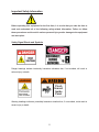
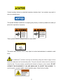
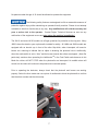
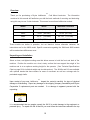
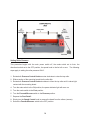
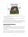
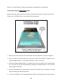
COLD-MOUNT LAMINATOR SERIES OPERATORS MANUAL Models JM18, JM26, JM44, JM54 Manual Version 10-07 2 Welcome to the World of Drytac Over the past three decades, Drytac has evolved into one of the world‟s most highly regarded manufacturers of products for graphics finishing and display. Our core product line consists of a wide range of pressure-sensitive, heatset and thermal overlaminating films. In addition, we offer an extensive line of mounting adhesives, backing films, inkjet media, finishing equipment, accessories, and banner stands. Our Start To Finish strategy sums up Drytac‟s unique ability to manage all phases of the customer experience: product quality and performance, manufacturing and distribution, training and technical support and the industry‟s best customer service. Jet Mounter™ Professional Quality Entry-Level Models JM 18 and JM26 These solid mid-size models deliver superior results for beginners and experienced users alike. Easy to set up and operate, the JM18‟s and JM26‟s are widely used by photography studios, picture framers, digital art studios and other creative shops. Standard features include: all-steel construction, variable speed electric drive, forward and reverse, foot pedal control, silicon rollers, photo-electric safety stop and supply shaft. Since the JM18 has many of the same features as the JM26 consider the references in this manual pertaining to the JM26 are applicable to the JM18. Jet Mounter™ Wide Format Laminators Drytac‟s Pressure-Sensitive Cold-Mount Models deliver economy and versatility for graphics finishing. The JetMounter™ motorized laminator series is engineered by Drytac to deliver a combination of performance and value unequalled in the finishing industry. Compatible with any pressuresensitive overlaminating film. JetMounters are also ideal for permanently mounting graphics onto cardstock, foam board, MDF or rigid PVC board. All electric models include: variable-speed electric drive, silicone rollers, all-steel construction, forward and reverse, supply shaft, foot pedal and photo-electric safety stop. These three heavy-duty wide-format models,( JM44,JM54,and the new JM63) are the culmination of our three decades in the mounting and laminating business. Equipped with the performance features our customers demand, JetMounter wide format models are unmatched for value. 3 Table of Contents Important Safety Information ...............................................................................5 Specific Moving Instructions .........................................................................9 Overview ......................................................................................................10 Unpacking and Installation ...........................................................................10,11 JM Components ...........................................................................................12 Component Illustrations ...............................................................................12,13 Setting Roller Pressure .................................................................................14 Adjusting Shaft Tensions ..............................................................................15 TM Mounting With the JetMounter Series Laminators Mounting Board Selection ............................................................................16 Adhesive Selection .......................................................................................16 Pre-coating the Mounting Board ...................................................................17 Mounting a Graphic to a Pre-Coated Board .................................................18 TM Laminating with the JetMounter Series Laminators Selecting a Laminate Film ............................................................................19 Single Unmounted Graphic...........................................................................20 Single Mounted Graphic ...............................................................................21 Laminating Multiple Mounted Images ...........................................................22 Using a Leader Board...................................................................................23 Carrier Boards ..............................................................................................24 Preparing Mounting Boards ..........................................................................24,25 Care and Maintenance ..........................................................................................26 Service .........................................................................................................26 Technical Specifications ...............................................................................27 Contact Info ..................................................................................................28 Warranty.................................................................................................................29 Replacement Parts .......................................................................................30 B Revision Functional Requirements............................................................31 4 Important Safety Information Before operating this equipment for the first time, it is crucial that you take the time to read and understand all of the following safety-related information. Failure to follow these procedures could result in serious personal injury and/or damage to the equipment and work piece. Safety Signal Words and Symbols Danger headings indicate imminently hazardous situations that, if not avoided, will result in serious injury or death. ! Pinch Hazard Inside Panel Warning headings indicate a potentially hazardous situation that, if not avoided, could result in severe injury or death. 5 Caution headings indicate a potentially hazardous situation that, if not avoided, may result in minor or moderate injury. This symbol indicates a statement of company policy directly or indirectly related to the safety of personnel or protection of property. ! ! Pinch Hazard Inside Panel Pinch point. Keep hands clear during operation. These symbols indicate a dangerous pinch hazard exists. This caution label indicates that a heavy object is involved and assistance is needed to avoid injury. TM The JetMounter performs mounting and laminating using two rollers to apply uniform pressure to adhesives and overlaminating films. The point where the rollers touch the material is called the Nip. This area creates a potential pinch hazard for fingers or other objects. DO NOT OPERATE THIS EQUIPMENT IF YOU ARE UNWILLING TO ACCEPT THIS HAZARD! TO AVOID INJURY, ALWAYS KEEP YOUR FINGERS AWAY FROM THE NIP AREA. 6 No persons under the age of 16 should be allowed to operate the equipment. The following safety features are designed to offer a reasonable measure of protection against injury while maintaining an operator-friendly machine. Please do not attempt to disable or alter their functionality in any way. Any modifications will void the warranty and pose a serious risk to the operator. Contact Drytac Technical Services as soon as any malfunction of the equipment occurs and stop using the machine immediately! The JM 18 and some JM 26 models use a finger guard bar for protection at the nip point. Many JM26‟s have the electric eyes or photocells installed for safety. All JM44 and JM54 models are equipped with an electric eye in front of the roller Nip which, when interrupted, will sound a buzzer as a warning to indicate that an object is breaking the photocell circuit. Additionally, when the mode switch is set to “Auto” and the buzzer sounds the rollers are stopped. (Note: Be particularly cautious when operating the JetMounter TM in the Foot Pedal mode because in this Mode the rollers will NOT STOP when the photocells are interrupted. An audible alarm will sound, but the rollers will continue to be powered at a reduced speed). Prior to operating the laminator, always check that the photocell and buzzer are working properly. Select the Auto mode and use a piece of cardboard to block the photocells to confirm that the alarm sounds and the rollers stop. 7 The JM44 and JM54 JetMounters are also equipped with Red Emergency Stop buttons located on both sides of the front or on the top on each side of the laminator. The Emergency Stop Button will stop the machine instantly. Stopping the machine in the Foot mode can also be accomplished by lifting your foot off the pedal, turning the speed to zero (0) OR turning off the power switch. DO NOT operate this equipment when you are alone. As with all motorized equipment, it is advisable that other adults be present to assist if required. DO NOT operate the JetMounter TM while under the influence of alcohol, prescription drugs or any other substance that could impair your judgment or reaction time. Remove any jewelry such as rings, bracelets and necklaces prior to operating the equipment. Keep loose clothing, neckties, artificial fingernails, long hair and anything else that might easily be drawn into the rollers away from the machine. Turn the JetMounter TM Power OFF if you are loading adhesives or film, cleaning the rollers or performing other activities that require close proximity of your fingers to the Nip. This will avoid the possibility of inadvertently starting the machine. Keep all safety guards in place and your fingers away from the Nip area when the machine is operating. Always work at a slow speed until you become familiar with the machine. Exercise caution when lifting rolls of laminate and adhesive due to their weight. Use assistance to avoid personal injury or damage to the equipment and materials. Prior to lifting a supply shaft into the laminator, position the T-Slot in the hub on the machines‟ right side to receive the shaft. The use of an assistant is strongly recommended. 8 Always disconnect the laminator from the power supply before removing any panels for service. When using a large supply roll, be aware that a pinch hazard can exist between the top roller and supply shaft. When working from the rear of the laminator the operator must be aware of the Nip point of the contacting rollers and exercise extreme caution to avoid injury. The sound this machine generates at the operators‟ position is less than 70dB. Keep this manual near the machine for future reference. Also check our website for any additional or updated safety information. (www.drytac.com) An instructional DVD and a demonstration/training session from a Drytac representative are TM also available so you can become familiar with all the features of your new JetMounter . Contact our Customer Service Department for details or if you have any questions about the operation of this equipment. (Contact information can be found on page 26). Specific Moving Instructions: TM The Drytac JetMounter is to be handled with care to avoid personal injury or collateral damage. Whenever the machine is moved, we strongly recommend utilizingTMat least two people. The adage: “Better safe than sorry,” applies here. The JetMounter stands are designed with fixed wheels on one side and lockable swivel casters on the other for a very good reason. When moving the machine, the movers should be positioned at both sides. Do TM not push the JetMounter from the front or back! This eliminates the possibility of having the machine tip over onto the mover or their helper. 9 Overview Thank you for purchasing a Drytac JetMounter TM Cold Mount Laminator. The information contained in this manual will familiarize you with the basic methods of mounting and laminating using this easy-to-use 2-roller laminator. This manual covers three JetMounter models: Model Width Maximum Laminate JM18 25.5” (64.8 cm) 18.25” (46.4cm) JM26 33.25” (84.5cm) 26.25” (66.7cm) JM44 52.75” (134.0cm) 44.125” (112.1cm) JM54 62.5” (135.3cm) 54.125” 137.5cm) These models are similar in operation, but not identical. Unless otherwise indicated, the instructions are for the JM26 model. Specific comments regarding the JM44 and JM54 models will be made where differences occur. Unpacking and Installation Select a clean, well-lighted working area that allows access to both the front and back of the machine. Position the machine on a level, sturdy surface that can support the weight of the machine and is at an optimum working height for the operator. (See Technical Specifications Chart on page 26 for individual weight and size dimensions). The JM 44‟s and 54‟s are available with optional stands that have casters for ease of movement as well as a storage rack for preloaded supply shafts. TM Upon receipt of your new JetMounter , inspect the carton(s) carefully for signs of physical damage or mishandling. Report any damage to the shipping company immediately and Drytac Corporation if replacement parts are needed. If no damage is apparent proceed with the unpacking. It is recommended that two people unpack the JM 26 to avoid damage to the equipment or personal injury. To unpack the JM 44 and 54 you must follow the instructions affixed to the top 10 of the crate in the sequence described. If the instructions are missing be sure to contact Drytac Technical Services before attempting to unpack or install the machine. Due to the weight of the JM44 and 54 laminators a hoist or suitable lift must be used to position the machine on an appropriate table or stand. JetMounter TM laminators, depending on the country in which the machine was purchased, are supplied in either a 115 VAC or 230 VAC versions. The power requirements for your particular machine are marked on the rear panel adjacent to the power connector. Please confirm that you have the correct power source available at the chosen location. If there are any questions about electrical requirements for the equipment, please contact a qualified electrician prior to attempting to power up the machine! IMPORTED AND DISTRIBUTED BY www.drytac.com JETMOUNTER MODEL SERIAL NUMBER DATE OF MANUFACTURE MAX. FEED RATE WEIGHT V ~ AC A Hz Be absolutely certain that the voltage supplied at the outlet corresponds with the voltage marked on the plate attached to your machine. Do not rely on the cord or outlet configuration to determine the correct power supply voltage! ALLOW ENOUGH WORKSPACE AROUND THE MACHINE TO BE ABLE TO FEED AND REMOVE YOUR WORKPIECE SAFELY! It is recommended that the machine be placed so that at least three feet of space from the front and back beyond the largest piece of material you will use be provided to insure adequate accessibility and safety. For example, if your work piece were a four-foot by eight-foot foam board, you would need to allow a minimum 11 of eleven feet of space in front and eleven feet of space in the rear of your machine. Always consider this rule a necessity prior to beginning your work. JetMounter TM Components 1. The main On-Off switch (rocker switch located on the back of the machine). This switch should be in the “OFF” position when loading or unloading adhesives or film, cleaning the rollers or performing other activities that require close proximity of your fingers to the Nip. 2. The Auto/Foot/Reset switch. This two-position switch is used to choose the mode of operation between “Foot” and “Auto”. The photocell safety feature functions differently in each position, review the safety information prior to selecting the mode of operation. Once the photocell is tripped or the Emergency Stop has been activated, you must first remove the obstruction or correct the cause for the shut down. To reset the machine you must reset the circuit breaker on the back of the machine and then toggle the Auto/Foot/Reset switch from the position it was in when the interruption occurred. 3. The Foot Pedal switch should be located on the floor within easy reach of the operator and is used to activate the roller when the Auto/Foot switch is in the “Foot” mode. 4. The Forward/Reverse switch (on front control panel) is used to select the direction of the roller rotation. Upon start up, place the switch in the “OFF” position. Reverse only operates in Foot mode. 12 5. The Speed Control knob. Rotating the knob to the right will increase the speed of the roller in either “Foot” or “Auto” mode. Upon start up, rotate the knob all the way to the left to the zero position. 6. The Pressure Control Knobs are located on the top of each side. They adjust the top roller height and pressure. Rotate both Pressure Control Knobs counter-clockwise to raise the top roller. (See “Setting Roller Pressure” to adjust the pressure properly). 7. The Supply Shaft holds the adhesive or laminate material, while the Take Up or wind-up shaft holds the release liner. When either of the shafts is installed, the T-slot end must be oriented properly to fit in the drive mechanism located on the right end of the machine, (as you face it from the front). The operator and the assistant should consider this prior to lifting the loaded shaft into position. Once in position, be alert to the possible pinch hazard at the left or un-driven end. 13 Setting Roller Pressure This procedure begins with the main power switch off, the mode switch set to Auto, the directional switch set to the OFF position, the speed knob to the far left or zero. The following steps apply to setting the roller pressure ONLY. 1. Rotate both Pressure Control Knobs counter-clockwise to raise the top roller. 2. Slide a section of the mounting board into the roller Nip. 3. Rotate both Pressure Control Knobs clockwise to lower the top roller until it makes light contact with the mounting board. 4. Turn the main switch to the ON position; the power indicator light will come on. 5. Turn the mode switch to the Foot position. 6. Turn the Forward/Reverse switch to the Reverse position. 7. Depress the Foot Pedal*. 8. Slowly turn the Speed Control knob to remove the board from the rollers (reverse). 9. Switch the Forward/Reverse switch to the OFF position. 14 10. For optimal results, rotate both Pressure Control knobs approximately 1/8 of a turn clockwise to slightly lower the roller (after the board has been removed). NOTE: The Foot Pedal acts as a safety device. When the mode switch is set to the Foot position, the laminator will not operate unless the Foot Pedal is depressed. For continuous operation set the mode switch on the control panel to Auto. Adjusting Shaft Tensions on JM44 and JM54 Models: JetMounter TM JM44 and JM54 models are equipped with a motorized Take Up Shaft on the front of the machine. This shaft winds up the release liner from mounting adhesive and over laminating film rolls during processing. Also on these models, both the Take Up shaft and the Supply shaft are equipped with Tension Control Knobs. By adjusting these knobs you control the speed of the shafts as they unwind or wind up material. It is important to adjust these settings so that there is an even tension on the adhesive or film during processing. The objective is to apply enough resistance on the film to keep it firm and flat, but not so much as to stretch or distort it. It is also critical to maintain even tension settings on both sides of the film. Turn the Tension Control Knobs clockwise to increase roll tension and counter-clockwise to reduce tension. 15 Supply shaft tension: When feeding adhesive or film into the rollers, the primary objective is to maintain the feed at the same rate as the rollers pull the material through the Nip. Take Up shaft tension: The Release Liner should be pulled away from the adhesive at a steady rate that allows it to “lift” at a point just before the material enters the Nip. Mounting with JetMounter TM Series Laminators Mounting Board (Substrate) Selection: The selection of a proper mounting board/substrate is very important. Common materials used are: • Foam Boards: (FomeCor®, GatorBoard®, HartBoard® etc.) • Illustration Board • Rag Board • MDF (medium density fiberboard) • Corrugated plastic boards: CoroPlast® • Rigid Plastic Boards (Sintra®, styrene, etc.) • Tempered hardboard: Masonite® Adhesive Selection Once the mounting board has been selected, determine whether to pre-coat the material with adhesive or to purchase pre-cut and pre-coated boards. While the use of pre-cut, pre-coated materials will save time, coating your own mounting board is more economical and allows for maximum flexibility in terms of sizing and substrate selection. Pre-coating the Mounting Board Pre-coating a mounting board means applying a mounting adhesive to one side of the board so that a graphic image can be mounted to the board later). The use of a Leader Board is recommended for this process. 1. Adjust rollers for proper pressure (see page 13). 16 2. Load the roll of PSA (pressure-sensitive adhesive) onto the Supply shaft so that the material can be pulled toward the user from the underside of the roll with the adhesive side facing UP (the release liner side should be in contact with the roller as shown in the Illustration). 3. Pull the adhesive off of the roll so that about 4” lies flat on the worktable and is draped in front of the rollers. 4. Lay your Leader Board on top of the exposed adhesive material on the worktable; then push the Leader Board and adhesive into the Nip (the „Nip‟ of your laminator is the point where the rollers make contact). When pushing the Leader Board into the adhesive, make sure it is parallel to the rollers. 5. Position your first mounting board behind and against the Leader Board. Check for proper alignment, and feed through the rollers (in either AUTO mode or via FOOT switch). Feed one board after another as needed. Trim the excess adhesive off of the board. 6. Your mounting boards are now pre-coated with pressure-sensitive adhesive, which is still protected by the release paper. The pre-coated boards can be used for immediate mounting or stored for future use. 17 TIP: When an image is going to be laminated with a gloss overlaminating film, the use of very smooth substrates with glossy surfaces (such as Masonite®) is preferred. This will minimize the effect of board imperfections, (i.e. “orange peel”) in the finished product. For models JM44 and MJ54, adjust the Supply shaft tension properly (page 14). NOTE: We recommend placing a „Tail Board‟ behind the last production board (this can be the same board used as a leader board/starting panel). This is especially important when precoating foam board. Mounting a Graphic to a Pre-Coated Board 1. Adjust the rollers for proper pressure (see Page 13). 2. Expose the adhesive on the board by folding back approximately 1” (2.5cm) of the release liner. 3. Using the folded-back release paper as a temporary support bridge, align the print onto the board and then proceed to “tack”(which means to stick or press down) the leading edge of the print onto the exposed adhesive. 4. Run a Leader Board of the same thickness as your mounting board through the rollers so that the back edge of the Leader Board is at the nip of your machine. 18 5. Square your mounting board with the tacked print against the edge of the Leader Board and drape the print over the top roller. 6. Run the mounting board/adhesive/image through the rollers while simultaneously pulling the release liner away from and off of the board. (JM44 and JM54 models have automatic Take Up shafts on the front of the chassis. You may choose to unwind the Release Liner onto the Take Up shaft during this process, rather than pulling it by hand. See page 14 for information on setting the Take Up Shaft tension). Laminating with JetMounter Series Laminators Selecting a Laminating Film Select an appropriate overlaminating film for the surface of your image based on aesthetics and the conditions under which it will be displayed. Drytac offers a wide variety of films to match your specific output and application. Please consult your Drytac catalog for descriptions of available film choices. There are several types of laminating jobs that can be performed on JetMounter laminators. The following are the most common applications. To prevent adhesives from sticking to the rollers and to provide a reusable, standard working surface, the use of a silicone-coated board (also 19 known as a “Carrier Board”) is highly recommended. (See page 22 for instructions). Laminating a Single Unmounted Image Before processing, make sure that the image is clean and free of dust or specks of lint (an AntiStatic cloth or Anti-Static Wisk is recommended for this purpose). 1. Raise the top roller and insert the Carrier Board. Set roller pressure as shown on page 10. 2. Pre-cut a sheet of overlaminating film from the roll. (The sheet should be larger than the image by approximately 1” on each side and bottom, and 2” on the top). 3. Peel and fold back approximately 2” of release liner from the top edge of the overlaminating film. Tack the film on the Carrier Board by pressing the exposed section of film onto the leading edge of the board. 4. Start the Carrier Board into your laminator using the Foot Pedal mode. Stop before the edge of the laminating film reaches the rollers. 5. Lift up the remainder of the overlaminating film (which is still protected by the release liner) 20 and slide the image face up underneath it. Stop before it makes contact with the exposed part of the adhesive. It is important to keep the film adhesive away from the artwork until the whole assembly is under pressure and traveling through the JetMounter TM. 6. Lay the laminating film over the top of the upper roller. While holding up the edge of the peeled back release liner with one hand, start the rollers and apply the overlaminating film to the surface of the image. Pull up and away on the release paper as your work piece travels through the laminator. Ensure that the release paper does not reach the point where the image makes contact with the top roller. Be sure to complete this step with a consistent motion and do not stop until the entire image has passed through the rollers. 7. The laminated image can now be easily removed from the silicone-coated Carrier Board for trimming and mounting. Laminating a Single Mounted Image Before processing, make sure that the images are clean and free of dust or specks of lint (an Anti-Static cloth or Anti-Static Wisk is recommended for this purpose). 1. Raise the top roller and insert the mounted image into the roller Nip. Adjust the roller pressure as described on page 13. 2. Pre-cut a sheet of overlaminating film from the roll. The sheet should be larger than the image by approximately 1/4” on the sides and bottom and 3” longer on the top. 3. Peel and fold back 2” of release paper liner exposing the adhesive of the laminating film. 4. Tack approximately 1-1/2” of the laminating film to the Leader Board, but not over the mounted image. 5. Insert the Leader Board with the laminating film tacked to it into the Nip. Advance the Leader Board and the film through the Nip until the upper laminating roller securely pinches the film. (The trailing edge of the Leader Board should be at the pinch point of the rollers.) 6. Lay the laminating film over the top of the upper laminating roller. Make sure that the folded release paper liner is easily accessible. 21 7. Slide the mounted image into the Nip area and allow its edge to make contact with the edge of the Leader Board. 8. While holding up the folded edge of the peeled back release paper with one hand, start the rollers and apply the laminating film to the surface of the image. Pull up and away on the release liner as you advance to ensure that the liner does not reach the Nip area. Process your work with a consistent motion and do not stop until the entire image has passed through the rollers. 9. Trim excess overlaminating film from the edges of the image. Laminating Multiple Mounted Images 1. For higher volume jobs, select a roll of laminating film slightly wider than the mounted images you intend to laminate. 2. Install the overlaminating film on the Supply shaft so that the material can be pulled toward the user from the bottom of the roll with the Release Liner side facing up. 3. Adjust the rollers for proper pressure (see page 13). 22 4. Pull several inches of the overlaminating film off the roll. Separate the overlaminating film from its release liner (approximately 3-4”) and drape it onto the in-feed table in front of the rollers. Keep the release liner away from the film while pushing the Leader Board and film into the roller Nip. 5. Position the first mounted image to be laminated against the back of the Leader Board. Check for proper alignment, and feed through the rollers of your laminator (in Auto mode or with foot pedal). Feed one print in right after another, as needed. 6. Carefully separate prints with a razor blade or utility knife. Trim off the excess film. JM44 and JM54 models have automatic Take Up shafts on the front of the chassis. You may choose to unwind the Release Liner onto the Take Up shaft during this process, rather than pulling it by hand. (See page 14 for information on setting Take Up Shaft tension). Using a Leader Board A Leader Board (also referred to as a “starting panel”) is recommended for use when mounting and laminating with JetMounter TM laminators. A Leader Board is fed into the roller Nip first, followed by the actual mounting/laminating project to be processed. We highly recommend this 23 tool to help set proper pressure for both mounting and laminating prior to processing your work. The Leader Board should be the same width and thickness of your production mounting board and about 6-8” long. You should also make a Tail Board, which is used behind the last production board. The Tail Board is especially recommended for mounting to foam board. Carrier Boards When processing un-mounted images, we recommend you use a silicone-coated board to prevent adhesives from sticking to the rollers. This board is called a Carrier Board, and it provides a re-usable, standard working surface. It will be used when laminating your image prior to mounting it onto a mounting board/substrate. It is common practice for finishing professionals to stock Carrier Boards in several different sizes to accommodate various artwork formats. Manufacturing Carrier Boards Making a Carrier Board is basically the same process as pre-coating a mounting board. Instructions for this process are found on page 15. When the mount board is coated with the adhesive, the silicone-coated release liner provides a slick, non-stick surface on which to laminate images. Be sure to use a “self-wound” adhesive with a silicone treated liner for this purpose. 2: Preparing Mounting Boards Preparing Mounting Boards Once you have decided on the most appropriate adhesive/mounting board combination for your application, it is important that you properly prepare your board before coating. Although often overlooked, this can be the most important step when mounting a print or artwork for display. Foam Boards (E.G. FOME-COR®, ETC.) The surface of these types of substrates is porous and often contains particles that can spoil an otherwise perfect mount. Clay-coated surfaces such as Fome-Cor®, Foam-X® and similar boards should simply be wiped with a TacCloth™ to remove dust particles. 24 Mat Boards/Mill Boards To prepare mat board or millboard for mounting, use the Anti-Static Wisk™ brush to remove dust particles and other debris. Hardboard (E.G. MEDIUM DENSITY FIBERBOARD, MASONITE, ETC.) To prepare hardboard substrates for mounting, wipe down the surface with a TacCloth. If the surface contains irregularities, use sandpaper to remove them, and then wipe the surface with a TacCloth. Please note: Due to their highly absorbent properties, do not wipe down the surfaces of any of these substrates (i.e. foam board, mat/millboard or hardboard) with a moist rag. Using a TacCloth to wipe down foam board. Tip: It is important that you remove dust and other debris from your prints prior to mounting. 25 Care and Maintenance CAUTION: Unplug the machine before performing any service or maintenance. Cleaning: In order for your JetMounter TM to operate efficiently, be sure to clean it regularly with a soft cloth. A neutral mixture of soap and water can be used for this purpose. To remove heavy dirt and adhesive residue we suggest the use of 99% isopropyl alcohol. Do not use thinner or a metal brush to clean the rollers. Rollers: In order to extend the life of your JetMounter laminator it is strongly recommended that the rollers be separated when the machine is not in use. Fuses: There are two replaceable fuses on your JetMounter located on the rear panel where the power cord enters the machine. One is actually in the power cord receptacle. The other is in a separate holder next to the power cord. Fuses are 5x20mm 1, 2 & 8 A depending on the particular machines‟ voltage requirements. The use of any other fuse may endanger the operator and/or machine and invalidate the warranty. Lubrication: Lubricate the drive chain located behind the right hand end cover every six months, with a premium brand chain lubricant. Disconnect power before lubricating the chain. No other parts require lubrication. Service Before contacting Drytac for service assistance, please double-check to make sure that the JetMounter TM is still connected to a live power outlet. Next, check both fuses. For further troubleshooting assistance, please contact Drytac Technical Services. See Contact Information on the page 28. 26 TM JetMounter TECHNICAL SPECIFICATIONS Roller Width Roller Diameter JM18 JM26 JM44 JM54 18.25”/46.4cm 26.25”/ 66.7 cm 44.50”/ 113.0cm 54.50”/ 134.4cm 2.5”/ 6.35cm 2.4”/ 6.1cm 4”/ 10.2cm 5”/ 12.7cm Roller Construction Steel-with high-release silicone covering. Width 25.5”/64.8cm 33.25”/ 84.5cm 61”/ 153.9cm 70.5”/ 179.1cm Depth 11.75”/29.9cm 12.2”/ 31cm 19”/ 48cm 19”/ 48cm Height 13”/33.0cm 12.28”/ 31cm 19”/ 48cm 19”/ 48cm Weight 51 lbs / 23kg 53 lbs/ 24kg 243 lbs/ 110kg 331 lbs/ 150kg Maximum Opening Max. Material Diameter Power Requirements .75” / 1.9cm 0.375”/ 0.95cm 1”/ 2.5cm 1”/ 2.5cm 8.0/20.32cm 10”/ 25.4cm 10 “/ 25.4cm 10”/ 25.4cm Speed Range 2.5 – 18fpm 2.5 – 18 fpm 3 – 10 fpm 2 - 10fpm 3”/ 7.6cm 3”/ 7.6cm 3”/ 7.6cm 3”/ 7.6cm Core Size Power Consumption Fuse Specifications 115 VAC or 230 VAC* 50/60 Hz 50W One 1A or 2A fuse in power receptacle*. One 8A in adjacent holder. Both are 5x20mm Fast-Acting glass fuses. PACKAGED FOR SHIPMENT Weight 57 lbs. 58.5 lbs/ 26.55kg 287 lbs/ 130.2kg 390 lbs/ 176.9kg Width 30” 37.5”/ 95.25cm 66”/ 167.64cm 76”/ 193.04cm Depth 15” 15”/ 38.1cm 23.5”/ 59.69cm 23.5”/ 59.69cm Height 15” 15”/ 38.1cm 25”/ 63.5cm 25”/ 63.5cm *Fuse rating for Europe is 1A, and for North America use a 2A.. TM Note: The JetMounter Stands are approximately 29.71” (755mm) tall, making the overall height of the assembled unit 48.71” (1237 mm). On a JM44/54 attached to a stand, the distance from the floor to the feed table is approximately 34.58” (878.33 mm). 27 CONTACT INFORMATION Drytac Corporation (USA) Drytac Europe (UK) 5383 Glen Alden Drive Filwood Road, Fishponds Richmond, VA 23231 Bristol BS16 3RY, United Kingdom Toll Free Phone: 800-280-6013 Phone: +44 (0) 117-958-6500 Toll Free Fax: 800-622-8839 Toll Free Phone: 0845-070-0660 (UK only) e-mail: [email protected] e-mail: [email protected] Drytac Canada, Inc. 220 Caldari Road Concord, Ontario Canada L4K 4L1 Toll Free Phone: 800-353-2883 Toll Free Fax: 877-437-9822 e-mail: [email protected] JetMounter TM Registration Information COMPANY NAME: ADDRESS: CITY / STATE: MODEL #: SERIAL #: PURCHASE DATE: WARRANTY CARD RETURNED ON: BY: 28 WARRANTY We thank you for your purchase of the JetMounter TM laminator and want to assure you that we will do our best to see that your experience with your new machine is a positive one. Every Drytac machine is designed and manufactured to give many years of dependable service. TM To achieve the best results from your JetMounter , the machine should be set up and operated in accordance with the instructions included in this manual. TM Should the original JetMounter purchaser experience any problem due to faulty materials or workmanship within 12 months of the purchase date, Drytac or their dealer will arrange for the machine to be repaired, replaced or refunded at Drytac‟s discretion. After the warranty period has elapsed, Drytac will provide all reasonable assistance and product support to resolve any problems that may arise. Please return your warranty card as soon as possible. This will help us more efficiently assist with any problem you may encounter. You will find a section for recording this important information for your records and any future parts or service requests on page 27 of this manual. Normal wear and tear, any damage to the silicon rollers, damage due to abuse, improper operation or installation is not covered by this warranty. Conditions that will void the warranty include-but are not limited to; failure to follow the instructions contained in this manual, unauthorized changes or modifications to the machine or the stand (where applicable) in any manner, misuse of the machine for purposes other than specified in the Operators Manual. Drytac will not be responsible for any damage or consequential damage caused by the machine. Please feel free to contact Drytac if you have any questions or problems. TM Before calling Drytac Technical Services, complete the JetMounter Registration Information on the previous page and have it available for reference. 29 Replacement Parts for the JetMounter Series Laminators Parts Applicable to Most Models Part Number Pressure/Tension Knob Speed Control Switch with Knob Motor Switch, Fwd./Rev Mode/Reset Switch On/Off Switch JMS-01 JMS-03 JMS-04 JMS-05 JMS-09 JMS-10, JMS-10E for European JMS-10UK for UK application Power Cord JM 18/26 Parts Part Number JMS UK fo JM 18 Silicon Roller JM 18 Roll Shaft Core Adapter for JM 18/26 Foot Control for JM 18/26 JM 26 Silicon Roller JM 26 Roll Shaft JMS1-01 JMS1-02 JMS12-03 JMS12-04 JMS2-01 JMS2-02 JM 44 Parts Part Number Silicon Roller Supply Shaft JMS4-01 JMS4-03 JM 54 Parts Part Number Silicon Roller Supply Shaft JMS5-01 JMS5-03 JM 44/54 Parts Part Number 1A Fuse- European Models 2A Fuse-All Other Models 8A Fuse- All Models Pressure Adjustment Handle Circuit Breaker JMS45-04 JMS45-02 JMS45-03 JMS45-13 JMS45-15 The list above does not include all service parts available. For further parts or service information please contact Drytac Technical Services (see page 28 for Contact Information). 30 B Revision Functional Requirements ACTION PROGRAMMED SOFTWARE FUNCTIONS Photocell AUTO MODE Operation Alarm LED No Green Photocell interrupted Normal operation at set speed Machine stops Yes Flash Red Photocell cleared Ready to start No Green E-Stops Activated Will not Run No Flash Yellow Press and Hold Rev. Button Jog speed Rev. Yes REV Green Power Up or E-Stops Reset=Needs Reset Will not Run No Yellow FOOT MODE FOOT pedal pressed, FWD mode Set speed, FWD No Green Photocell interrupted. FP still depressed Jog mode Yes Flash Red Photocell cleared. FP still depressed. Jog mode No Green Photocell cleared. FP dep. Switch to Auto FWD, Set speed No Green FOOT pedal released Machine stops No Green Restart by FP, no buttons pressed Set speed FWD No Green Press and hold REV in Foot Mode, Jog mode REV Yes REV Green Release REV button while depress FP Jog mode REV Yes REV Green No Green No Flash Green Yes Flash Green FWD button pressed Table Down, FOOT pedal released. (JM63 only) Machine Stops, Ready to start Will not Run Table Down, FOOT pedal pressed. (JM63 only) Jog mode In Rev. with Foot on pedal- press AUTO 10/09/2007 31