1
Acorn Multimedia Expansion Unit
User Guide
Acorn Multimedia Expansion Unit
User Guide
Copyright © 1990, 1991 Next Technology Corporation Limited. All rights reserved.
Copyright © 1990 - 1992 Cumana Limited. All rights reserved.
Copyright © 1993 Acorn Computers Limited. All rights reserved.
Published by Acorn Computers Technical Publications Department.
No part of this publication may be reproduced or transmitted, in any form or by any
means, electronic, mechanical, photocopying, recording or otherwise, or stored in any
retrieval system of any nature, without the written permission of the copyright holder
and the publisher, application for which shall be made to the publisher.
The product described in this manual is not intended for use as a
critical component in life support devices or any system in which failure
could be expected to result in personal injury.
The product described in this manual is subject to continuous development and
improvement. All information of a technical nature and particulars of the product and
its use (including the information and particulars in this manual) are given by Acorn
Computers Limited in good faith. However, Acorn Computers Limited cannot accept
any liability for any loss or damage arising from the use of any information or
particulars in this manual, or any incorrect use of the product. All maintenance and
service on the product must be carried out by Acorn Computers' authorised dealers or
Approved Service Centres. Acorn Computers Limited can accept no liability
whatsoever for any loss or damage caused by service, maintenance or repair by
unauthorised personnel.
If you have any comments on this manual, please complete the form at the back of the
manual and send it to the address given there.
Acorn supplies its products through an international distribution network. Your
supplier is available to help resolve any queries you might have.
ACORN/ the ACORN logo and ARCHIMEDES are trademarks of Acorn Computers
Limited.
MS-DOS and WINDOWS are trademarks of Microsoft Corporation.
All other trademarks are acknowledged.
Published by Acorn Computers Limited
ISBN 1 85250 135 9
Part number 0493,726
Issue 1 , March 1993
Guidelines for safe operation
The equipment described in this guide (the 'unit) is designed and manufactured to comply with international
safety standards EN60950 ( BS7002) and is intended for use only as a computer expansion unit. It must not be
used for other purposes. It is most important that unpacking and operation is carried out in accordance with
the instructions given in this guide. In the interests of continued safe and reliable operation, observe the
following guidelines:
•
Keep the unit at a room temperature of +5°C to +35°C (+41° to +95° Fahrenheit) and a relative humidity
of 20% to 80% (non-condensing). As a rough guide, if you feel much too hot, cold or humid, the
conditions are probably too extreme for the unit as well.
•
Avoid sudden extremes in temperature, exposure to direct sunlight, heat sources (e.g. electric fan heater)
or rain.
•
Make sure that the unit is standing on a suitable rigid horizontal flat surface, allowing enough space
for air to circulate when it is in use.
•
Ensure that any wires and cables are routed sensibly so that they cannot be snagged or tripped over Don't
tug or twist any wires or cables, or use them to hang or lift the unit.
•
Make sure you have read and understood any installation instructions supplied with upgrade kits
before attempting to fit them. If you have any doubts, contact your supplier
•
Keep the original packaging in case you need to transport the unit, and avoid bumping, jarring or
dropping it in transit.
•
Keep the plastic bags contained in the packaging away from children.
•
Keep the plastic bags protecting the leads, but do not leave the leads in the plastic bags for long periods of
time.
•
If you're going to move the unit, make sure you park any hard disc heads first (if fitted).
•
Switch off and unplug the unit from the power outlet on the wall at night, or if you're not going to use the
unit for a few days.
•
Switch off and unplug the unit and any accessories before opening the unit (e.g. to install an upgrade).
•
The unit should be operated with the top cover (which also acts as a fire enclosure) secured, to
ensure the correct airflow through the unit.
•
DON'T attempt to open any display or monitor unit, whether supplied with the unit or not.
•
DON'T drop the unit or subject it to excessive bumping and jarring.
•
DON'T spill liquids on the unit. If liquid does spill, turn the unit off immediately and take it to your
supplier for assessment.
•
DON'T obstruct or poke objects through the ventilation openings in the unit casing or the power supply,
or cover them with anything.
•
DON'T balance any objects, or stand equipment weighing more than I 6kg (33Ibs) on top of this unit.
Warning: this equipment must be earthed
If the plug supplied is not suitable for the power supply in your country, please consult your supplier.
UK information
The mains lead supplied is already fitted with a moulded plug incorporating a 3A fuse. If it does not fit your
socket-outlet, the plug should be removed from the mains lead and safely disposed of. The flexible cord
insulation should then be stripped back as appropriate. A suitable alternative plug should then be fitted. If the
replacement plug is intended to take a fuse, then a 3A fuse must be used. If you need to replace the fuse in the
mains plug supplied, then you must use a 3A fuse ASTA-approved to BSI 362.
As the colours of the cores in the AC power lead of this unit may not correspond to the coloured markings
identifying the terminals in your plug, proceed as follows:
•
The core which is coloured green and yellow must be connected to the terminal in the plug which is
coloured green and yellow, or is marked by the letter E or by the earth symbol
•
The core which is coloured blue must be connected to the terminal that is coloured black or marked
with the letter N.
•
The core which is coloured brown must be connected to the terminal which is coloured red or marked
with the letter L.
Never use mains plugs with the fuse carrier omitted. In the event of the loss of the fuse carrier, either replace
with a carrier of the same type and manufacturer or replace the moulded plug with another mains plug, wired
as detailed above
iii
Guarantee (valid in UK only)
This equipment is guaranteed by Acorn Computers Limited ("ACORN") against mechanical and
electrical defects subject to the conditions set out below.
Note
Items which by their nature or design only have a restricted life are not guaranteed beyond such life.
Period of validity
This guarantee shall be valid for a period of twelve (12) months from the date of purchase.
Other conditions
1
This guarantee is personal to the original purchaser, is not transferable and shall not be valid
unless the equipment was purchased from ACORN or from an approved ACORN supplier.
2
This guarantee will be invalidated if the equipment is misused or damaged or is modified in any
way without the written consent of ACORN or if any original component or accessory has been
replaced by any component or accessory of a type not recommended or approved by ACORN, or
if operated other than in accordance with the Multimedia Expansion Unit User Guide.
3
Any claims made under this guarantee must whenever possible be made through the supplier from
whom the equipment was originally purchased. If this is not possible a claim may be made to any
other approved ACORN supplier appointed by ACORN to service the equipment (a list of whom
can be supplied on application). This guarantee together with proof of the date of purchase must
be produced when any claim is made. Any costs of carriage to and from the supplier must be paid
by the purchaser.
4
If ACORN agrees with the supplier that the equipment should be forwarded to ACORN for repair
then ACORN will arrange for collection and return of the equipment at no charge. In all other
cases the supplier will be responsible for effecting any necessary repairs in accordance with
ACORN's service policy. Any repairs under this guarantee will be carried out at no cost to the
original purchaser.
5
If any equipment returned is found to comply with its original specification ACORN reserves the
right to charge a reasonable fee for testing the equipment and for return carriage.
6
The liability of ACORN under this guarantee shall be limited to the cost of repair or complete
replacement (at ACORN's discretion) of equipment which proves to be defective.
7
ACORN does not accept liability for any loss or damage during transit to or from the supplier or
ACORN, but every effort will be made to investigate claims of loss or damage if these arise.
THIS GUARANTEE DOES NOT AFFECT OR PREJUDICE THE PURCHASER'S STATUTORY RIGHTS.
Guarantee procedure
To claim under this guarantee, proof of date of purchase is required. This is provided by your copy of the
invoice from the supplier from whom the equipment was originally purchased. Keep the invoice safe and
produce it to support any claim you may make under this guarantee.
You may find it useful to make a note in the box below of the serial number, date of purchase and
details of any upgrades fitted, and quote them in any correspondence.
iv
Contents
Contents v
About this Guide vii
What you should already know vii
If you have problems vii
Conventions vii
About the Multimedia Expansion Unit 1
Unpacking the Multimedia Expansion Unit 1
Handling the Multimedia Expansion Unit 2
Parts identification 2
Hardware and firmware requirements 4
Installing the SCSI expansion card 5
Installing the standard expansion card (CAO06) 5
Installing the mini expansion card (CAO08) 12
Configuring the Multimedia Expansion Unit 15
Connecting the Multimedia Expansion Unit to your computer 15
Configuring the computer 19
Configuring your RISC OS computer from the desktop 19
Setting up PC Soft to read CD-ROM discs 20
Using Compact Discs 23
Handling Compact Discs 23
Loading Compact Discs 23
Ejecting a CD-ROM disc 24
Using CD-ROM discs 25
Using CDFS 25
Reading PC-format CD-ROM discs using PC Soft 26
V
Contents
CDPlayer 29
The main CD Player window 30
The Keypad window 30
The Setup window 32
Quitting CDPlayer 32
Expanding your system 33
More about SCSI 34
Adding new SCSI devices 37
SCSIMgr 39
Security 39
Installing and running SCSIMgr 40
The Devices window 42
The Partitions window 47
The Drives window 50
SCSIMgr Menu items 52
Quitting the SCSIMgr application 54
SCSIDiag 55
ChangeFSl 57
Using ChangeFSl 57
ChangeFSl in more detail 58
Using the command line 63
SCSI * Commands 63
CDFS * Commands 64
Configuring SCSI drives from the command line 66
Configuring CD-ROM drives from the command line 67
Altering the default configuration of your system under PC Soft 68
Technical specification 69
Power Supply Unit (PSU) 69
Operating temperature 69
Audio specifications 69
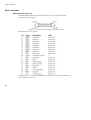
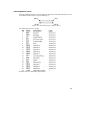
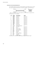
SCSI connectors 70
Troubleshooting guide 73
Index 75
vi
About this Guide
This Guide tells you how to install the Multimedia Expansion Unit, and — having
done so — how to use both the unit itself and the software supplied with it.
Information is provided in the sequence necessary to quickly get you up and operating.
Later chapters give you help on expanding your system, and on sorting out any
problems you may have.
What you should already know
Before reading this Guide, you should be familiar with the material in your
computer's Welcome Guide. In particular you should already have a good idea of
how the desktop operates, and you should have read the Guidelines for safe
operation printed near the front of the Welcome Guide.
If you have problems
If your computer starts behaving unexpectedly, or doesn't do anything at all, see both
the chapter If things go wrong in the Welcome Guide (which has solutions to most
common problems), and Appendix C: Troubleshooting guide on page 73 of this
Guide.
Conventions
Typefaces
The following conventions are used in this guide:
• Menu names and options are shown in bold type; for example:
Choose SCSIDirCache from the Configure submenu.
• Example commands are shown in Courier type; for example:
*Devices
Since all characters are the same width in Courier, this makes it easier for you to
tell where there should be spaces.
Vii
Conventions
Command syntax
Special symbols are used when defining the syntax for commands:
• Italics indicate that you must substitute an actual value. For example, drive
means that you must supply an actual drive number.
•
Braces indicates that the item enclosed is optional. For example, [K] shows that
you may omit the letter K.
•
A bar indicates an option. For example, 0|1 means that you must supply the
value 0 or 1.
The mouse
The mouse has three buttons. From left to right their names are Select, Menu and
Adjust. The functions they perform depend on the application you are using. For some
general principles refer to the Welcome Guide supplied with your computer.
Viii
1
About the Multimedia Expansion
Unit
The Multimedia Expansion Unit is an expansion unit that is style-matched to an A4000
or A5000 computer, and that comes fitted with a single CD-ROM drive. CD-ROM
discs are gaining popularity throughout the world as computer users in commerce,
education and industry discover their potential for vast amounts of data storage, their
audio/visual capabilities, and their convenient storage and handling. The combination
of thousands of pages of text, images (both moving and still) and audio will help you
discover a wealth of study, research and entertainment opportunities.
Expanding your system
The Multimedia Expansion Unit has been designed to offer you complete flexibility for
your future needs — it has built in expandability. You may install a further two SCSI
devices in the Multimedia Expansion Unit: for example, a hard drive, a magneto-optical
drive or perhaps a second CD-ROM drive. You can also connect additional SCSI
devices, either as external cased units (similar to the Multimedia Expansion Unit), or
possibly fitted inside your main computer unit. Audio capabilities have been built in,
along with provision for installing a stereo power amplifier.
If you intend to expand your system, make sure you don't miss out the chapter
Expanding your system on page 33, as it contains important advice and instructions.
Unpacking the Multimedia Expansion Unit
The first thing you should do is to unpack your Multimedia Expansion Unit and
check that all the components are present.
To use the Multimedia Expansion Unit your computer must have a compatible SCSI
expansion card fitted. The Multimedia Expansion Unit is available with two different
SCSI expansion cards, suitable for the two sizes of expansion card slots that Acorn
computers have: either a standard sized one, or a mini sized one. Alternatively, should
your computer already have a suitable SCSI expansion card fitted, you can purchase the
Multimedia Expansion Unit without an expansion card. (However, you may need to
upgrade the software fitted to your existing card; see SCSI expansion cards on page 4.)
If you have any doubts, contact your supplier.
1
Handling the Multimedia Expansion Unit
Verify that all of the following items are present:
• one Multimedia Expansion Unit
• one SCSI terminator block
• one CD caddy (which holds and protects the CD in the CD-ROM drive)
• one audio cable (also used to connect the Multimedia Expansion Unit to your
computer)
•
one mains lead.
Depending on the model you have purchased, you may also have been supplied in
separate packaging with:
•
one SCSI interface, numbered either CAO06 (a standard expansion card) or
CAO08 (a mini expansion card)
•
one SCSI interface cable, numbered MAC-50TP (used to connect the
Multimedia Expansion Unit to the SCSI interface)
• one floppy disc of support software. If any of these items are missing,
please contact your supplier immediately.
It is a good idea to keep the packaging the Multimedia Expansion Unit arrived in, just
in case you have to store or ship it in the future.
Handling the Multimedia Expansion Unit
The Multimedia Expansion Unit can be damaged if it is mishandled. You should
handle it carefully, as dropping or sharply knocking the unit may result in optical
misalignment and unreliable operation. Placing it in very hot, humid conditions may
result in overheating and damage.
When moving the unit, always ensure that you have removed any CD caddies from its
CD-ROM drive(s), otherwise you may damage the drives. For full safety information,
see Guidelines for safe operation on page iii.
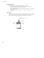
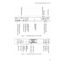
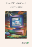
Parts identification
To familiarise yourself with the Multimedia Expansion Unit, please take a moment to
study the diagrams opposite. You will be connecting cables to and perhaps changing
settings on the box, so it will be helpful to know where everything is.
Note that some of the parts fitted to the Multimedia Expansion Unit do not have any
function on the basic unit, but are fitted ready for use by upgrades. In particular, the
CD2 line out phono sockets are only used if you fit a second CD-ROM drive, and the
Hard disc drive LED is only used if you fit a drive that does not have its own LED
fitted to its front panel (as the standard CD-ROM drive does).
2
About the Multimedia Expansion Unit
3
Hardware and firmware requirements
Hardware and firmware requirements
Computers
The Multimedia Expansion Unit will work with any computer that is fitted with RISC
OS 3 or later, and that has a SCSI interface. As noted above, expansion cards are
available with the unit – both in standard and mini sizes – so you can add a SCSI
interface to your computer.
If you need to upgrade your version of RISC OS, a good time to do so is while fitting
the SCSI expansion card, since you need to open your computer to do either.
Computers fitted with a mini expansion card SCSI interface can read or write only 8
bits at a time; this is a restriction imposed by the computer's connector for the
expansion card, which does not have enough pins to pass 16 bits of data at a time to the
card.
Archimedes 300 or 400 series computers were supplied fitted with a MEMCI memory
controller chip. If you have not already upgraded this chip to a MEMC1A, you might
like to consider doing so, as you will get much faster data transfer rates. (With a
MEMC1, the computer can read or write only 8 bits at a time, whereas with a
MEMC1A it can transfer 16 bits at a time.)
SCSI expansion cards
You may have bought the Multimedia Expansion Unit without a SCSI expansion card,
because your computer already has one fitted. To use the CD-ROM drive, your SCSI
expansion card must contain version 2.13 or above of the CDFS (Compact Disc Filing
System) software. To find out, type at the command line:
*Help CDFS
You will either get a message giving the version number of CDFS fitted to your SCSI
expansion card, or the message 'No help found' if CDFS is not present at all. If you do
not have a sufficiently recent version of CDFS, you should contact your computer
supplier.
If you already have a SCSI expansion card fitted, you can obviously skip the next
chapter (Installing the SCSI expansion card), and should move on to Configuring the
Multimedia Expansion Unit on page 15.
4
2
Installing the SCSI expansion
card
This chapter tells you how to fit the two types of SCSI expansion card that are
optionally supplied with the Multimedia Expansion Unit: a standard expansion card (
below), or a mini expansion card (page 12).
Installing the standard expansion card (CAO06)
The CAO06 SCSI expansion card can be used with the Acorn Archimedes 300, 400 and
540 series of computers, with all R-series computers (e.g. the R260), and with the
A5000. Using it you can attach a selection of SCSI devices without further modification
In order to fit the expansion card you will have to remove the cover of the computer unit
and one of the blanking plates at the rear of the machine. The only tools you will require
for this are No. 1 and No. 2 Pozidriv screwdrivers.
If you do not feel confident about carrying out this installation, take the expansion card
and your computer to your supplier who will fit the card for you. A charge may be
levied by the supplier for installing the expansion card; such a charge shall be entirely at
the discretion of the supplier concerned.
Disassemble the computer
Important! To protect the expansion card from static electricity
• handle the card as little as possible, preferably by the edges
• avoid touching components or the connector.
5
Installing the standard expansion card (CAO06)
Preparation
For systems fitted with a hard disc drive, make sure that the drive heads are parked
before attempting to move or otherwise disturb the unit. To do this, choose Shutdown
from the Task manager menu.
Acorn Archimedes and R-series
1
Switch off the computer at the rear and disconnect it from the mains supply by
unplugging the power supply cable. Unplug any peripherals that are attached and
remove them from the computer completely.
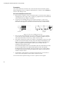
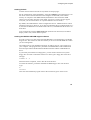
2
Locate the screws holding the top cover in place (see Figure 2.1 The screws
holding the top case). Remove the three screws at the top rear of the computer,
then remove the single screw located on each side of the unit, towards the front.
3
4
Figure 2.1 The screws holding the top case
Once you have removed the three rear screws and the two side screws, slide the
cover to the rear of the computer, then remove it completely. Slightly spring the
sides of the lid outwards, if necessary, to make it easier to slide.
Check that a backplane is fitted to the computer. The backplane consists of a small
printed circuit board mounted vertically on the main PCB. If the backplane is not
fitted, you will have to purchase one and install it, according to the instructions
which are supplied with the backplane, before you can continue with the
installation of the expansion card.
The standard backplane fitted to the Archimedes 400 series and the R140 can take
up to four single-width or two double-width expansion cards. The optional
backplane fitted to the Archimedes 300 series can take up to two single-width or
two double-width expansion cards (provided the latter require no more than one
interface connector each).
5
If a backplane is fitted, but has no expansion card socket free, you will have to
remove one of the expansion cards in order to install a new one.
You can now fit the expansion card; go to Fit the expansion card on page 8.
6
Installing the SCSI expansion card
A5000
1
Switch off and disconnect the computer from the mains supply, then switch off
and disconnect all peripherals (including the keyboard).
2
Place the computer on a work surface with a clean, soft covering like a woollen
blanket (not synthetic) or a piece of cardboard and turn it over so that it rests on
its top cover.
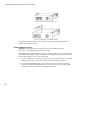
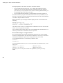
3
Remove all six screws holding the metal cover in place (see Figure 2.2 A5000 top
cover fixing screws). Store them somewhere safe.
4
Rest the computer on its base again and slide the cover back towards the rear of
the computer (see Figure 2.3 Removing the top cover). Remove the cover
completely.
5
Some models of the A5000 have an EMC case shield which fits over the inner
case (see Figure 2.4 Removing the EMC shield). To remove this, unscrew the five
fixing screws on the righthand side of the computer, as seen from the rear. The
shield has interleaved tabs which fit around the edges of the case. Slide the shield
off the computer carefully; there is a hole on the top to help you slide the shield
off by inserting a screwdriver.
Figure 2.2 A5000 top cover fixing screws
7
Installing the standard expansion card (CAO06)
Figure 2.3 Removing the top cover
Figure 2.4 Removing the EMC shield
The standard backplane fitted to the A5000 can take up to four single-width or two
double-width expansion cards.
Fit the expansion card
Warning: Some components on expansion cards can be damaged by static
electricity. Avoid touching components on the card.
The backplane has upper and lower expansion card slots. These correspond to the two
full-width blanking plates fitted to the back of an unexpanded machine. Each blanking
plate is held in place by screws, one at each end.
8
1
Choose the expansion card slot you are going to use, and remove the corresponding
blanking plate by unscrewing the two screws holding the plate in position.
2
Use the supplied blanking plate, T-piece and two screws to make the expansion
card up to the full width of the machine (unless of course there is already another
expansion card in the computer alongside filling the gap).
Installing the SCSI expansion card
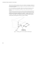
3
4
Once you have made the expansion card backplate up to the correct width/ you
can install it into the computer. Figure 2.5 Fitting an expansion card into the
lower slot (Archimedes) shows an expansion card fitting into one of the positions
in the computer. The illustration shows an Archimedes computer, but the same
principle applies for A5000:
Figure 2.5 Fitting an expansion card into the lower slot (Archimedes)
To fit the expansion card, support the backplane firmly with one hand and push
the connector on the card into one of the sockets on the backplane. The connector
should be securely seated, i.e. the rear plate of the expansion card should be flush
with the rear of the computer case. It is important that you offer the expansion
card up to the backplane at right angles to it and that you align the connectors;
otherwise, you may bend the pins or break or disconnect the backplane itself. It
does not require great force to install the expansion card correctly. If the
expansion card will not seat easily, remove the expansion card and try again.
9
Installing the standard expansion card (CAO06)
When you have fitted an expansion card to your computer, the backplane should be in
a vertical position, assuming that the expansion card is fully inserted and screwed into
the rear of the computer.
For some combinations of Archimedes and R-Series machines and expansion cards,
however, the top of the backplane may appear to 'lean' towards the front of the
machine.
If this is the case, you must insert the two spacers found in this package. Each spacer
should be inserted between the internal face of the expansion card backplate and the
metal clips on the rear plastic moulding of the machine, so that the fixing screws pass
through both the backplate and the spacers (see Figure 2.6 Fitting spacers to the
expansion card backplate). This should result in the external face of the expansion
card backplate panel being flush with the rear plastic moulding.
Figure 2.6 Fitting spacers to the expansion card backplate
10
Installing the SCSI expansion card
When you have done this, you may need to straighten the backplane, to ensure that
the connectors are correctly mated. To do this, take the following steps:
1
Slacken off the two screws fixing the backplane support metalwork to the base
metalwork and power supply.
2
Holding the expansion card stationary, ease the backplane towards a vertical
position until the faces of the interlocking connectors on the expansion card and
backplane are touching.
3
Retighten the two screws slackened earlier.
[f you do not require the two spacers, simply secure the expansion card to the rear of
the computer case by inserting a screw at each end of the expansion card backplate.
Reassemble the computer
Once the expansion card has been correctly installed, replace the top cover of the
computer, following the disassembly instructions in the reverse order.
The expansion card has now been installed.
Test the card is correctly installed
When you have completed reassembly, set up the computer as shown in the Welcome
Guide, and switch on the monitor. When the monitor has warmed up, switch on the
computer.
Check that you have correctly installed the upgrade, by pressing F12 to get to the
command line, then typing
Podules
If the card has been correctly installed, the message CDFS & SCSI Expansion
Card (or similar) will be displayed. Press Return to get back to the Desktop. If the
message did not appear, shut down and switch off the computer, remove the cover and
check that the card has been correctly installed. Reassemble and re-test. If the computer
still does not acknowledge the presence of the expansion card, switch it off and consult
your supplier.
11
Installing the mini expansion card (CAO08)
Installing the mini expansion card (CAO08)
The CAO08 SCSI expansion card can be used with the A3000, A3010, A3020 and
A4000 computers. Using it you can attach a selection of SCSI devices without further
modification.
A3000
The CA 008/A SCSI expansion card is intended to be fitted to BBC A3000 computers
by an Acorn Authorised Dealer, who will install and test the card. A charge may be
levied by the dealer for installing the card; such a charge shall be entirely at the
discretion of the dealer concerned. This card and your Acorn A3000 computer (both in
their original packaging) should be taken to an Acorn Authorised Dealer for installation.
A3010, A3020 and A4000
Instructions are included for fitting the expansion card to these computers. If you do not
feel confident about fitting it yourself, take the card and your computer (in its original
packaging) to an Acorn Authorised Dealer, who will install and test the card. A charge
may be levied by the dealer for installing the card; such a charge
shall be entirely at the discretion of the dealer concerned.
Acorn Computers Limited cannot accept any liability for damage done to the
product during installation of internal upgrades, whether or not carried out in
accordance with the instructions in this document.
Disassemble the computer
To remove the top cover and locate the internal expansion card connector, follow the
instructions in Appendix E: Inside the computer in the Welcome Guide.
Note that the only screws you need to unscrew to remove the top cover of A3010 and
A3020 computers are those marked with the symbol shown here.
12
Installing the SCSI expansion card
Remove the plastic and metal blanking panels shown in the Welcome Guide. Keep
these safe, in case you want to remove the upgrade in the future.
Fit the expansion card
1
Remove the expansion card from its packaging. Be careful to avoid touching the
pins.
2
Check that all pins are straight. If any appear crooked or splayed, please contact
your supplier.
Offer the expansion card up to the computer as shown in Figure 2.1 Fitting the
expansion card into an A3010. The diagram shows an A3010, but the A3020 is
very similar in appearance, and the same principle applies to the A4000. The
connector pins on the card fit into the sockets SK5 SK7, SK8 and SK9 (the four
computer expansion card sockets shown in the Welcome Guide).
3
Figure 2.1 Fitting the expansion card into an A3010
The expansion card back plate fits inside both the plastic outer case and the metal
lining of the computer, so that the fixing screws will pass through the holes in the
case, and screw into the threads on the card back panel.
4
Locate the pins on the card carefully in the sockets on the computer, then press
the expansion card firmly down to make the connection.
5
Secure the card by screwing the two fixing screws through the rear of the
computer's case and into the threaded holes in the expansion card.
13
Installing the mini expansion card (CAO08)
Reassemble the computer
Reassembly is explained in Appendix E: Inside the computer in the Welcome
Guide.
Test the card is correctly installed
When you have completed reassembly, set up the computer as shown in the Welcome
Guide, and switch on the monitor. When the monitor has warmed up, switch on the
computer.
Check that you have correctly installed the upgrade, by pressing F12 to get to the
command line, then typing
Podules
If the card has been correctly installed, the message CDFS & SCSI Expansion
Card (or similar) will be displayed. Press Return to get back to the Desktop. If the
message did not appear, shut down and switch off the computer, remove the cover and
check that the card has been correctly installed. Reassemble and re-test. [f the
computer still does not acknowledge the presence of the expansion card, switch it off
and consult your supplier.
14
3
Configuring the Multimedia
Expansion Unit
This chapter tells you how to connect the Multimedia Expansion Unit to your
computer, in its basic configuration with a single CD-ROM drive fitted. The simple
instructions below assume that your computer has no SCSI devices fitted to it apart
from those (if any) with which it was supplied, such as the internal hard disc fitted to
the A540 and R200 series.
You should read the more detailed instructions in Expanding your system on page 33 if:
•
you wish to configure and connect further SCSI devices, including any that you
may have added to the spare drive bays in the Multimedia Expansion Unit
•
you have already added SCSI devices to your computer
•
you have altered the SCSI ID of any devices supplied as standard with your
computer (e.g. by moving jumpers on the internal hard disc fitted to the A540 and
8200 series.)
You should also see the instructions supplied with your other SCSI devices.
Connecting the Multimedia Expansion Unit to your computer
Position the Multimedia Expansion Unit
The Multimedia Expansion Unit is designed to be stacked. It can support a maximum
weight of 16kg, which should be spread evenly over its top rather than be concentrated
in a small area. If you do stack it, ensure that everything is stable.
You don't have to stack the Multimedia Expansion Unit, and can instead place it
wherever is convenient in the space you have available. Don't forget you'll need to have
access to the CD drive and controls!
15
Connecting the Multimedia Expansion Unit to your computer
Our recommendations are:
A5000 and A4000
Place the Multimedia Expansion Unit and monitor on top of the computer unit (as
shown on this guide's cover).
Acorn Archimedes and R-series
Stack the Multimedia Expansion Unit and computer unit in whichever order is most
convenient; then place the monitor on top of the stack. Ensure there is no more than
16kg on top of the Multimedia Expansion Unit, and no more than 15kg on top of the
computer unit. As a guideline, if you're using a standard 14" colour monitor this
shouldn't be a problem, but if you're using a larger monitor its weight may be too much
for you to stack all three units.
Other computers
You can use the Multimedia Expansion Unit as a monitor stand, provided again that
the monitor weight does not exceed 16kg.
Connecting and configuring the Multimedia Expansion Unit
The first thing you must do is to connect the Multimedia Expansion Unit to your
computer, and ensure that it is correctly configured:
1 Ensure that power to the computer is turned off.
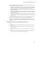
2 Locate the SCSI [D selector on the rear of the Multimedia Expansion Unit and check
the number shown is correct; it should be 6. If you need to change the ID, push one of
the buttons on the selector: one increases the number, the other decreases it.
3 Connect one end of the SCSI interface cable (numbered MAC-50TP) to the external
SCSI port on the interface card, and the other end of the cable to either of the SCSI
connectors on the back of the Multimedia Expansion Unit.
4 Plug the terminator block into the other SCSI connector at the rear of the Multimedia
Expansion Unit.
Connecting the audio signals
The Multimedia Expansion Unit has a preamplifier which mixes the sound from its CDROM drive(s) with the computer's sound. This mixed sound is output to two sockets: a
stereo jack socket on the front of the unit (suitable for use with headphones, mini
speakers or speakers in the monitor), and a pair of phono sockets on the rear of the unit (
suitable for use with an amplifier or speakers with a built-in amplifier). The slider
control on the front panel alters the volume output through both these sockets.
16
Configuring the Multimedia Expansion Unit
Using these sockets you can easily connect a single pair of headphones and/or a stereo
system to the sound from all your equipment:
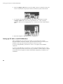
1 Push the 3.5mm stereo jack plug on one end of the audio lead into the headphones
32Ohm socket on the back of the computer. Push the two phono plugs on the other
end of the cable into the two Computer Audio In sockets on the rear of the
Multimedia Expansion Unit, using the red plug for the Right channel, and the other
plug for the Left channel.
2 If you are using headphones, mini speakers or speakers in the monitor, plug their
connecting lead into the stereo jack socket below the Acorn logo on the front of the
Multimedia Expansion Unit.
[f you are using an amplifier or speakers with a built-in amplifier, connect these to
the Mixed Line Out (Variable) pair of phono sockets on the rear of the Multimedia
Expansion Unit.
A stereo power amplifier upgrade is available for your Multimedia Expansion Unit,
enabling you to connect speakers directly to it. See your supplier for details.
Note that each CD-ROM drive also has an individual headphone socket and volume
control on its front panel, and a stereo pair of Line Out phono sockets on the rear panel
of the unit.
Plugging in and switching on the Multimedia Expansion Unit
Finally:
I Connect the power lead to the Multimedia Expansion Unit and to a power outlet
on the wall.
2 Switch on the mains supply for the Multimedia Expansion Unit (at the mains
outlet on the wall).
3 Turn the Multimedia Expansion Unit on by pressing the ON/OFF switch on the
front.
4 Turn on the rest of your system as usual. (If you're unsure what's the best order
in which to do this, see your computer's Welcome Guide.)
17
18
4
Configuring the computer
Filing System (CDFS) enables you to access data on a CD-ROM from
T hetheCD-ROM
RISC OS desktop. It is resident in a ROM on your SCSI expansion card, and is
loaded automatically when you power on your computer. The CDFS icon bar menu
enables you to configure your computer to suit the CD-ROM system attached to it.
This chapter tells you how to configure your computer so that you can use CDROMs; you only need to do so when adding or removing drives.
For details of how to use CDFS once you have configured it, see Using CD-ROM
discs on page 25.
Configuring your RISC OS computer from the desktop
To ensure the fastest boot up time, the following procedure should be followed:
1 Ensure all the peripherals and cables are connected.
2 Switch on the monitor, then the CD-ROM drive. The CD-ROM drive should
always be switched on before the computer.
3 Switch on the computer. CDFS will look to see if a CD-ROM drive is connected.
4 The CD-ROM icon will be displayed on the Icon Bar.
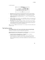
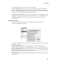
5 To configure the number of CD-ROM drives you have attached to your computer,
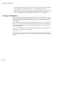
click Menu on the CD-ROM icon. The CDFS icon bar menu will be displayed:
19
Setting up PC Soft to read CD-ROM discs
6 Choose Configure, Drives then enter the number of drives connected. If only one
drive is connected, this step may be left out, but the boot-up time will be slower:
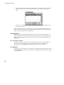
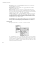
7 To configure the CD-ROM buffers, click Menu on the CD-ROM icon. Choose
Configure, Buffers then click on the required buffer size – 16K is normally
sufficient, unless you are swapping discs a lot, in which case 32K or 64K would be
better:
8 Reset the computer to implement the new configuration.
Setting up PC Soft to read CD-ROM discs
Many CD-ROM titles are written in PC format, so to get the best out of these,
PC Soft should be used in the computer. (PC Soft used to be known as the Acorn PC
Emulator.) The copy of PC Soft you use must be version 1.6 or later.
If you are using MS-DOS, you must have version 3.3 or higher, with CD-ROM
extensions.
If you are using DR-DOS, you must have a version with CD-ROM extensions. At the
time of going to press, such versions were not yet available – but this is likely to change.
You should see your supplier for details of DR-DOS compatibility, availability, and
installation.
20
Configuring the computer
Loading PC Soft
Load PC Soft as instructed in the PC Soft Guide accompanying it.
Set the configuration of the emulated PC, using the Configure option from the PC icon
bar menu. Choose EGA and ECD for titles using this screen mode, with 128K of
memory for computers with 2MB of RAM, and 256K for those with more RAM.
Choose VGA for titles using this screen mode. (Versions 1.6 and I.7 do not support
VGA, but you can choose EGA+ for a partial emulation of VGA mode.)
By default, the CD-ROM drive will be configured as drive F. Additional drives will be
named G, H and so on. However, if you have four hard disc drives configured (drives CF) then the CD-ROM drive will install itself as drive G, and additional drives follow on
from there.
Now run PC Soft. Switch to Single task mode (from the icon bar menu) to be able to
display a full screen, and for faster response.
Loading the MS-DOS CD-ROM support software
PC Soft (version I.6 or later) when sold with MS-DOS is accompanied by a CD-ROM
Support disc. The software on this disc enables you to access the CD-ROM drive while
you are running DOS.
The software has its own installation program, to make it easy for you to install it on
your computer. This program alters your DOS AUTOEXEC.BAT and CONFIG.SYS
files and copies Microsoft MS-DOS CD-ROM extensions and the CD-ROM device
driver.
If you usually boot DOS from a floppy disc, you first need to format a new system
floppy disc on which to install the software. To do this, put a floppy disc in the drive
and type:
FORMAT A: /S
When the format completes, remove this disc from the drive.
To install the software, put the disc labelled CD-ROM Support disc into the drive.
Type:
A:
INSTALL
This starts the installation program. Follow the instructions given on the screen.
21
Setting up PC Soft to read CD-ROM discs
When prompted for a drive letter on which to install this software:
•
If you boot DOS from a floppy disc, type A. When the installation program
prompts for your boot disc, insert the newly-formatted system disc, and press
Space. When you are prompted to insert the disc containing MSCDEX.EXE, put
the CD-ROM Support disc back in the drive.
•
If you boot DOS from a hard disc, type the hard disc drive letter (typically C).
When the installation program has finished, reboot DOS from your hard disc, if you
have one, or else put your newly-created system disc back in the drive and hold down
Ctrl and Alt and press Delete to do this.
During the reboot cycle a message should be displayed on the screen similar to the
following:
MSCDEX Version 2.20
Copyright © Microsoft Corp. 1986
Drive F: = Driver CDFSEM unit 0
This indicates that the driver is loaded and the CD-ROM drive has been allocated the
letter F: for access purposes from DOS.
Your computer will now behave like a PC with a CD-ROM drive attached. There is a
summary of common PC commands in the PC Soft Guide.
Recommended changes to configuration files
We recommend that you check that the following statements exist in the CONFIG.
SYS and AUTOEXEC.BAT files and amend or add them as necessary as some DOS
formatted CD-ROM discs require these settings before they can be used.
In the CONFIG.SYS file we recommend you add these lines:
FILES=20
BUFFERS=20
In the AUTOEXEC.BAT file your PATH should include the pathnames below, in the
order given:
PATH=C:\;C:\DOS;F:\
PATH=A:\;A:\DOS;F:\
(Hard drive users.)
(Floppy drive users.)
Of course, your PATH may also include other pathnames you have previously
added.
22
5
Using Compact Discs
you use Compact Discs (or CDs), you will need to know how to load them into
Before
the CD caddy. The caddy holds the CDs in the correct position within the CD-ROM
drive, and protects them from damage. Extra caddies are available from your supplier.
Handling Compact Discs
Treat your Compact Discs with as much respect as you would give to a vinyl record.
Handle CDs by the edge to avoid fingerprints. A very dirty CD will not operate
properly. Generally, you should not have to clean a CD, but if you do, follow the
instructions in Appendix C: Troubleshooting guide on page 73.
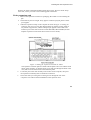
Loading Compact Discs
To use a Compact Disc with the CD-ROM drive you must first place the CD into the
CD caddy. The CD caddy is then inserted into the drive.
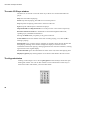
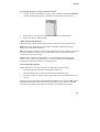
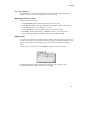
1 To open the caddy apply pressure as shown in the following diagram and lift the
plastic lid. Place the CD into the caddy with the label side up.
Figure 5.1 Using a disc caddy
When you have inserted a CD into the caddy, close the lid. You will hear and feel it
snap into place. When you have closed the lid you should be able to see the CD's
label.
2 Insert the caddy into the CD-ROM drive, making sure that the caddy is top side up (
you can read the CD's label) with the arrow on the caddy pointing towards the drive.
As you slowly push the caddy into the drive you will feel a little
23
Ejecting a CD-ROM disc
resistance about three quarters of the way in. Keep applying pressure until the caddy
clicks into the drive (just like pushing a 3 ½" disc into a floppy disc drive).
3 When the caddy is inserted you will see an amber light on the front of the drive
flicker for a few moments. This indicates that the drive is focusing on the CD. If it
fails to recognise the CD the mechanism will automatically eject the caddy.
Ejecting a CD-ROM disc
When you have finished using the CD-ROM and you have quit the CD-ROM, software,
simply dismount and eject the CD caddy like a floppy disc by pressing the eject button
on the front of the drive. Alternatively you can type *Eject from the Command line
when in CDFS.
The CD-ROM drive will eject the caddy about one third of the way out, and you can
then remove it. The CD should be stored either in the box in which it was supplied, or it
should be left in the caddy. If you are transporting the CD please return it to the case in
which it was supplied.
If the eject mechanism appears to fail, the drive may have been locked using the *Lock
command. To cancel this, use the command:
*CDFS:Unlock
If the disc still won't eject, as a last resort firmly push one end of a large paper clip into
the emergency eject button hole on the front of the CD-ROM drive; the caddy will be
ejected.
24
6
Using CD-ROM discs
The CD-ROM drive in the Multimedia Expansion Unit can be used with CD-ROM
discs formatted for use with RISC OS, or with CD-ROM discs produced to run under
MS-DOS. For the latter, you will need a copy of PC Soft to get full benefit.
Using CDFS
CDFS appears to the user very much like ADFS — all the usual RISC OS Filer
commands are available, although you cannot of course save to a CD-ROM. If a write
command is made to the CD-ROM drive, an error message will be displayed.
To open a directory display on a CD-ROM which has been inserted in the drive, click
on the CD-ROM drive icon on the icon bar. The contents of the CD-ROM will be
displayed by the RISC OS Filer:
25
Reading PC-format CD-ROM discs using PC Soft
RISC OS directory displays can be opened for PC CD-ROMs. PC file names are
translated to a format compatible with the RISC OS environment. You can view text
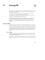
files using Edit in the same way as usual, and use ChangeFSI (see page 57) to convert a
wide range of graphics images to RISC OS sprites, which you can then view using
Paint. However, to run the programs included on such discs, you will need to use PC
Soft (see Reading PC-format CD-ROM discs using PC Soft below).
If you are not using CDFS
CDFS claims some memory each time you power on your computer. If you are not
using CDFS and need this extra memory, you can disable CDFS by typing
*Unplug CDFS
*Unplug CDFSDriver
*Unplug CDFSFiler
and then resetting your computer. When you need CDFS again, you can reinstall the
three modules by using *RMReInit for each one in a similar way, and then
rebooting.
Reading PC-format CD-ROM discs using PC Soft
Place a CD-ROM disc in the drive, and type
F:
(or whatever drive letter your CD-ROM drive is configured as).
You can now access PC-format discs in the normal way.
Consult the guide that comes with each title for information on playing CD-ROM
discs.
Do not try to access a CD-ROM through RISC OS (including via CDPlayer) and
through PC Soft at the same time.
Performance limitations
VGA images
Version 1.6 and I.7 of the Acorn PC Emulator (the old name for PC Soft) do not fully
support the VGA Bios. EGA+ is a partial implementation of VGA, but some VGA
images on PC format CD-ROM discs cannot be displayed fully. The title screens of
some discs are designed to be displayed in VGA mode, so such discs may not start off
very well. This does not, however, necessarily mean that the rest of
26
Using CD-ROM discs
the disc cannot be read correctly. Often the application will continue of its own
accord, or require Space or Return to be pressed. In some cases the lack of VGA
support will prevent the disc from running under the emulator at all.
Version 1.8 of PC Soft does support VGA.
Sound
Titles which attempt to play sound through the computer's own sound system can cause
program errors, unless you first configure sound in the program to be off. Most titles
are able to play CD-quality sound through the CD-ROM drive, so this problem does
not often arise.
Windows
Certain CD-ROM applications contain their own version of Windows on the CD-ROM
itself. These versions have often been modified in some way, and do not always work
correctly. We recommend that you do not use a version of
Windows supplied on CD-ROM, but an appropriate Windows application available
separately from a PC dealer.
Note that Windows 3.1 will not run under PC Soft.
27
28
7
CDPlayer
CDPlayer application allows you to play and control audio CDs using your
T hecomputer
and a CD-ROM drive, such as that in the Multimedia Expansion Unit.
CDPlayer is supplied on the Support Disc, and is already set up to use the CD_ROM
drive fitted to the Multimedia Expansion Unit. If you have changed its SCSI ID from the
default of 6, or if you wish to use any other CD-ROM drives, you should first read The
Setup window on page 32.
CDPlayer simulates all the functions of a CD audio player with all the normal functions
such as play, stop, track search, cue and review. It also has a very comprehensive
programming facility. All the functions, including drive select, are controlled using the
mouse.
To start the application, double-click on the CDPlayer icon; this loads the program and
displays its icon on the icon bar. Click on its icon to display the main CD Player
window, used to control the CD:
29
The main CD Player window
The main CD Player window
The basic set of controls work in the same way as those of a conventional audio CD
player.
Play starts the audio CD playing.
Pause stops the CD playing, but holds it in its current position.
Stop stops the CD playing, and returns to the start of the CD.
Eject stops the CD and ejects it from the CD player.
Skip backwards and Skip forwards move to the previous or next tracks respectively.
Rewind and Fast forward move backwards or forwards through the audio track,
speeding up as you hold down the button.
Moving the Slider takes you quickly to any point on the CD.
Track number shows the number of the track currently playing, or (as above) 00 if
nothing is playing.
Playing time gives you three choices of display. It normally shows the time the disc has
been playing. Clicking on this number changes the display to show the time the
individual track has been playing; clicking again shows the time left on the disc; clicking
again returns to the original display.
Total tracks/time gives the total number of tracks on the CD, and its total playing time.
Display keypad displays the keypad, the use of which is described in the next section.
The Keypad window
Clicking on the triangle icon or choosing Keypad from the CD Player menu will open
the Keypad window. You can use this window to select which tracks on the CD you
wish to hear and in which order you wish to hear them:
30
CDPlayer
To program the player to play a selection of tracks
1
Click on the first track number you wish to hear, and then on MEM. The Memory
window automatically appears, showing the tracks in the program memory:
2
3
Repeat this for any other tracks you wish to add to the program memory.
Play the tracks by clicking on Play.
Other program play functions
ALL adds a list of all the audio tracks available on the CD to the program memory.
RND clears the program memory, and creates a randomly ordered list of all the
audio tracks to the program memory.
RPT continuously repeats the tracks in the program memory until you click on the Stop
key in the CD Player window. If no program has been set, the CD instead repeats
continuously from start to finish.
CLR is used to clear the program memory. To clear all tracks from the program
memory, click Adjust on the CLR button. To clear individual tracks, highlight the
desired tracks and then click Select on the CLR button.
Notes on playing programs
When CDPlayer is set to play a program, the following restrictions apply:
•
The slider and slider bar cannot be dragged or clicked on.
•
The time display will only show the time the disc has been playing.
•
The main CD Player window must be open to allow the programmed tracks to be
played.
When playing a mixed mode CD (mixed audio and data tracks), using the ALL button
guarantees that all the audio tracks will be played, otherwise the drive will normally
stop when it encounters a data track, even if there are subsequent audio tracks.
31
The Setup window
The Setup window
Each CDPlayer can be used to control a single CD-ROM drive at one time, which is
selected using the Setup window. However, CDPlayer is supplied already set up to use
the Multimedia Expansion Unit in its default configuration, so you'll only need to
change the Setup if you are using more than one CD-ROM drive and/or SCSI interface,
or if you have changed the configuration of your Multimedia Expansion Unit from the
default (SCSI device 6, LUN 0, card number 0).
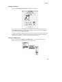
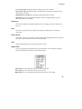
To open the Setup window, choose Setup from CDPlayer's icon bar menu:
Click on the + and - icons until the correct device, unit and card numbers are shown for
the CD-ROM drive you wish to use. If you're not sure what the numbers should be for a
particular drive, you can find them out using the Devices window of the SCSIMgr
application (page 42) or by typing at the command line:
CDFS:CDDevices
(see page 63).
It is not advisable to keep switching CDPlayer from one drive to another using the
Setup window. This operation should only be performed when CDPlayer is first started.
If you need to control more than one drive, you should start the CDPlayer application
as many times as you require and change each copy's setup individually before use.
Quitting CDPlayer
To quit the CDPlayer application, choose Quit from its icon bar menu.
32
8
Expanding your system
Expansion Unit is supplied with a CD-ROM drive; however, it has
ThebeenMultimedia
designed to allow for easy expansion. We recommend that you only fit
upgrades to the Multimedia Expansion Unit which are known to be compatible with it.
Expanding the Multimedia Expansion Unit's audio
You can expand the audio capabilities of the Multimedia Expansion Unit by fitting a
stereo power amplifier, allowing the direct connection of speakers to the unit.
Adding SCSI devices to the Multimedia Expansion Unit
The Multimedia Expansion Unit has a space for a 5¼" or 3½" device to be fitted with
front panel access – typically a removable media device such as a magneto-optical
drive or a second CD-ROM drive. You can add one further 3½" device inside the unit,
such as a SCSI hard disc drive.
Adding internal SCSI devices to your computer
Furthermore, the standard SCSI expansion card (CAO06) has a connector that you can
use to add internal SCSI devices – such as a SCSI hard disc – to your computer.
Fitting internal devices
If you fit an internal SCSI device – whether to your Multimedia Expansion Unit, or to
your computer – you must ensure these requirements are met:
•
There must be a free drive bay that will hold the SCSI device.
•
There must be sufficient power available from the power supply unit (PSU) to
meet the maximum power consumption of the device.
If the PSU is not sufficiently powerful, you will either have to fit a higher
specification PSU, or have to use an external PSU.
•
The device must not dissipate more heat than can be safely dispersed, even in hot
weather.
If you have any doubts over the suitability of a particular device for internal
installation, consult your supplier.
33
More about SCSI
You'll find full details of the Multimedia Expansion Unit in Appendix B: Technical
specification on page 69; these include its maximum operating temperature, and the
power available from its PSU. As a rough guideline, you may fit one additional device
– including the power amplifier – to the Multimedia Expansion Unit without upgrading
its PSU. A cooling fan may be required for devices with a high power consumption
Adding external SCSI devices
As the Multimedia Expansion Unit incorporates SCSI devices, you can add any
external SCSI device to your computer system by simply daisy-chaining the
devices. This is described below.
More about SCSI
Before you add further SCSI devices to your system, there are two simple – but
important – issues you need to understand. These are SCSI IDs, and termination.
SCSI IDs
Each SCSI device must have a unique SCSI ID in the range 0 - 7. The software uses
this ID to ensure it is 'talking' with the correct device.
The interface itself counts as a device, and its default ID is 7. This leaves IDs 0 - 6
available for other SCSI devices. There are no rules on which sorts of device should use
which IDs, but the scheme below is one that many people use:
•
IDs 0 - 3 are used for disc drives
•
ID 4 is used for a tape drive
•
ID 6 is used for a CD-ROM drive
•
ID 5 is used for other devices such as scanners.
The internal disc fitted to the A540 and R200 series has a SCSI ID of 0, and so fits
this scheme.
The method used to set SCSI IDs varies. It is typically done either using a selector
switch (such as that fitted to the Multimedia Expansion Unit), or a set of switches or
jumpers fitted to a circuit board on the device. See your devices' manuals for more
information.
34
Expanding your system
Termination
To work correctly, every SCSI bus must have a set of termination resistors connected to
each end, and nowhere else. If the bus isn't correctly terminated, data passing along the
bus may be corrupted.
The chapter Configuring the Multimedia Expansion Unit on page 15 described how to
set up the Multimedia Expansion Unit in its basic default configuration. If you add other
SCSI devices to your system, you have two choices:
•
Add the new device to one end of the SCSI bus (i.e. the external end, or the
internal end).
In this case you must terminate the new device, and remove the termination from
the device that was previously on that end of the bus.
•
Add the new device to the middle of the SCSI bus. In
this case the new device must not be terminated.
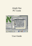
Internal devices
The standard SCSI expansion card (CAO06) has a connector that you can use to add
internal devices — in other words, devices that fit inside your computer's casing, such as
an extra hard disc. Before you connect any such devices, you'll need to know the
locations both of the connector for internal devices, and of the card's terminating resistor
packs (which provide the termination of the internal end of the SCSI bus):
Figure 8.1 CA006 SCSI expansion card: terminating resistors and SCSI connectors
The mini SCSI expansion card (CAO08) does not have a connector for internal
devices, and so we recommend that you do not try to fit them.
35
More about SCSI
The important rules when adding internal SCSI devices to your computer are as
follows:
•
If you don't add any internal SCSI devices to your computer, the interface is at one
end of the SCSI bus, and so its terminating resistors must remain fitted.
•
If you do add internal SCSI devices, the interface is no longer at the end of the
SCSI bus, and so you must remove its terminating resistors.
You must then ensure that the only the last device on the internal SCSI bus is
terminated. SCSI devices designed for internal fitting are typically terminated by
resistor packs fitted to sockets on a circuit board (i.e. just like the SCSI expansion
card), but you should check their manuals to be sure.
External devices
The important rules when adding external SCSI devices are:
•
The last device on the external SCSI bus must be terminated.
SCSI devices designed for external use are typically terminated by an external
block, such as that supplied with the Multimedia Expansion Unit (which you can
use on any SCSI device with the correct type of socket). However, some units (
especially older ones) may instead use resistor packs fitted to sockets on a circuit
board. Again, you should check your devices' manuals to find out how they are
terminated.
•
Any other devices connected to the external SCSI bus must not be terminated.
In particular, this means that:
36
•
If the Multimedia Expansion Unit is the only external SCSI peripheral attached to
your computer it must have its terminator block fitted.
•
If you disconnect all external SCSI devices from your machine, the interface
must have a terminator block fitted to its external SCSI socket.
Note that the Multimedia Expansion Unit's terminator will not fit this socket; you
will need to buy either a terminator that does fit, or an adaptor that allows you to
connect the Multimedia Expansion Unit's terminator.
Expanding your system
Adding new SCSI devices
Because there are so many different types of SCSI devices, we can't give precise
instructions that cover every possibility. However, if you follow the guidelines below
you shouldn't have any problems.
If you have any doubts, you should consult your supplier.
Read the manuals for your new SCSI device
Before you try to do anything, read the manuals supplied with your new SCSI device. In
particular, you should find out how the device is terminated, how to set its SCSI ID, and
whether there are any restrictions on what that ID may be. (In some rare cases, software
supplied with your device may assume that it has a particular SCSI ID.)
Decide the SCSI configuration you will use
Using the information from the new. SCSI device's manual, and the guidelines above
on SCSI IDs and Termination, decide to which device(s) you are going to connect the
new device (and hence whether it needs to be terminated), and what ID you will give it.
Check you have the correct cables
There are several different types of sockets in use for SCSI devices. Before you are
ready to connect your new device, you must have suitable cables available. When
purchasing your cable, ensure that the plugs on each end match the sockets on the
devices you are connecting.
Your cables must be high quality shielded cables designed for use with SCSI, otherwise
you may suffer from data corruption and poor reliability. Your cables must be as short
as possible; this improves both data transfer rates and reliability.
The total length of the SCSI bus (including any internal cabling) must not exceed 6m,
even with the best quality cabling.
Install the new SCSI device
When installing your new device, ensure your entire computer system is switched off,
otherwise you may damage components on your computer and/or your SCSI devices.
37
Adding new SCSI devices
Check SCSI IDs and termination
Before switching on your system, check that each device has a unique SCSI ID, and
that the SCSI bus is correctly terminated (i.e. at each end only).
Once you have switched on, you can use the Devices window of the SCSIMgr
application (page 42) or the *Devices command (page 63) to double-check the SCSI
IDs.
Switch on your system
Turn the Multimedia Expansion Unit on by pressing the ON/OFF switch on the front.
Turn on any other external SCSI units. Then turn on the rest of your system as usual. (If
you're unsure what's the best order in which to do this, see your computer's Welcome
Guide.)
Configure your computer and software
Depending on the device you have installed, you may then need to change your
computer's configuration, or to change the configuration of existing software (such as
CDFS), or to install and configure new software.
As well as the manuals supplied with your new SCSI device, you should also
consult any relevant parts of this guide: in particular Configuring the computer on
page 19, and Appendix A: Using the command line on page 63.
Prepare your device
Before you can use a read/write device it has to be formatted, partitioned and
mapped to your system. This can all be achieved using the SCSI device
management program SCSIMgr, as detailed in the next chapter.
Read-only devices such as CD-ROMs and scanners do not require any formatting etc.
prior to use, and are normally supplied with appropriate software for their installation
and use.
38
9
SCSIMgr
(short for SCSI Manager) enables you to set up and control the SCSI
SCSIMgr
devices attached to your computer, such as hard disc drives, magneto-optical drives,
CD-ROM drives, and the SCSI expansion card itself. Before using such devices with
your computer you may need to carry out a number of tasks such as formatting,
verifying and partitioning a hard drive, or setting the ID number of your SCSI expansion
card. SCSIMgr gives you a desktop interface with on-line help that will do all these tasks
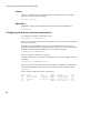
and more, and in a far simpler way than using the command line to do so.
Security
As with any software program which controls the set up of your computer system, e.g.
network management software, it is of paramount importance to be able to limit access
to those who are authorized. Therefore, SCSIMgr incorporates three levels of security
which should deny any unauthorized people from changing the SCSI settings you have
on your system.
Setting an entry password for SCSIMgr
You can set an entry password which is required to use the SCSIMgr application itself (
see Installing and running SCSIMgr on page 40). You can change this password
anytime you wish (see Password on page 52).
Warning!
This level of security does not mean that your SCSI settings cannot be changed; it
merely makes secure a particular copy of SCSIMgr. Your SCSI settings can still be
changed by other copies of SCSIMgr (say one with a different password), or from the
command line.
Disabling * Commands
If you want to increase security, you can prevent a computer's SCSI settings being
altered at the command line (see The Set Host ID button on page 46).
39
Installing and running SCSIMgr
Locking the system
A more secure way of ensuring that the SCSI settings are not changed is to lock the
system by setting a system password (see Lock System on page 52). Once the system is
locked you can change the SCSI settings only if the entry password for the copy of
SCSIMgr you are using matches the system password that was used to lock the
system.
If you want to alter a locked system, but the entry password for your copy of SCSIMgr
doesn't match, you'll need to start SCSIMgr (giving its current entry password), and then
change SCSIMgr's entry password so it does match the system password that was used
to lock the system (see Password on page 52). Of course, anyone else who knows the
system password might be able to do the same, so you shouldn't give it to anyone you
don't trust.
Warning!: If you've locked your system and have forgotten the system password,
you cannot bypass the security. The only way to gain access is to return your SCSI
expansion card to Cumana (telephone +44 483 503121) to be unlocked. Do not
return your copy of SCSIMgr.
Leaving SCSIMgr unattended
Finally, you should remember not to leave SCSIMgr running on an unattended
computer, as anyone with access to that computer can then alter its SCSI settings.
Installing and running SCSIMgr
SCSIMgr is supplied on the Support Disc. Before using SCSIMgr, you should copy it
either to another floppy disc, or to your computer's hard disc – if one is fitted.
To run SCSIMgr, double-click on its icon in the normal way. A password window will
be displayed:
40
•
If no entry password has yet been set the message will be Set New Password. If
you don't wish to set an entry password, just click on OK; otherwise type in the
entry password you wish to use for this copy of SCSIMgr, and then click on OK.
•
If an entry password has been set the message will read Enter Password.
Type the entry password for this copy of SCSIMgr, and click on OK.
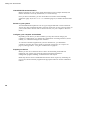
SCSIMgr
You will have to wait a few seconds while the computer searches for any SCSI devices
attached to your system. The main SCSI Manager window then appears. It is split into
four subwindows:
•
The Devices window shows the devices attached to your SCSI bus, and is used to
set them up (e.g. formatting, verifying, and controlling access); see page 42.
•
The Partitions window is used to show and to set up the partitions into which the
currently selected device is divided; see page 47.
Don't worry if it initially shows an error such as 'SCSI driver reservation error' (
as above); this is quite normal, and is explained later.
•
The Drives window is used to control which partitions of which devices appear as
drives on the icon bar; see page 50.
•
The fourth window, in the bottom right corner, is a Help window, which briefly
explains the function of the item beneath the pointer. You can get more detailed
help at any-time by selecting the appropriate window heading, or by clicking on
the help window itself.
You can close the main SCSI Manager window in the usual way by clicking on its
close icon. This does not quit the SCSIMgr program. To re-open the window click
SCSIMgr on the icon bar.
41
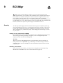
The Devices window
The Devices window
All the SCSI devices attached to your system, including the SCSI expansion card, are
listed in this window:
If there are more than four SCSI devices connected to your system, two scroll
arrows appear beside the list, which you can use to display those devices not
initially shown.
The list contains the following information about each of the devices:
Heading
Dev
Type
Size
Vendor
Product
Rev
Meaning
Device number: the first digit is its logical unit number (LUN), the
second its card number, and the third its SCSI ID number
Type of device (the 'Host' is the SCSI expansion card)
Capacity of device, in Megabytes
Name of device's manufacturer
Manufacturer's identifying code or name
Firmware version number
You cannot change any of the information contained in this list. You simply select the
device of your choice and relevant options in the form of buttons will appear below the
list.
42
SCSIMgr
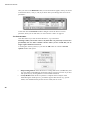
The Driver Flags button
The Driver Flags button is present for all devices except the host. If you click it, a
dialogue box appears with which you can control how the driver handles a particular
SCSI device:
•
Spread Reads spreads out read accesses to the drive very slightly, allowing more
time for other interrupts to run. Currently you need to turn this on if you are using
Acorn Replay from either a hard disc or a CD-ROM drive with an on-board cache;
this is the default. If you are using a CD-ROM drive without a cache you will need
to turn this off.
•
8 Bit Mode forces your interface to talk to the drive 8 bits at a time, rather than at
its default rate (which may be 8 bits anyway). You should leave this option turned
off; it is provided for diagnostic purposes only.
Both driver flags are stored in the EEPROM on the SCSI interface to which the selected
device is connected. They are stored on a 'per SCSI device' basis — that is, all devices
having the same last two digits in their device number share the same driver flags.
The Dismount button
The Dismount button is shown if the device you have selected is a writable device (e.g.
a hard disc) that is currently in use. or mounted:
At the same time, the Partitions window shows the message 'SCSI driver reservation
error', which indicates that you cannot change the device's partitioning because it is in
use.
43
The Devices window
Once you click on the Dismount button, several new buttons appear, which you can use
to format the device, verify it, and (if you know what you're doing) alter its low-level
parameters:
At the same time the Partitions window changes to show the device's current
partitions, which you can then alter; see The Partitions window on page 47.
The Format button
Click this button if you wish to format the device, e.g. a hard drive.
Warning!: When you format a device, any data that was previously stored on it is
permanently lost. So, don't reformat a device unless you are certain that you no
longer require the data stored on it.
A warning box will tell you this; if you click the OK button to continue a Format
Options window then opens:
44
•
Keep Existing Defects retains the device's existing defects list (a hidden file), and
any new defects located during verification will be stored in a new list. If you turn
this option off, any existing defects list will instead be deleted.
•
Certify Media makes the device perform a complete surface analysis of the
media during the format process, provided it supports this function (e.g. optical
media). You should normally do this for new media, but can avoid
SCSIMgr
doing so to speed up a re-format process. (For example, cerfifying a piece of
optical media may take up to an hour, whereas re-formatting without using this
option will only take a few seconds.)
•
Use Verified Defects uses the list of defects obtained from the last verify. If you
reformat using this option, and then verify the disc again, you should get no
reported defects.
The error list obtained from a verify is lost as soon as you change the selected
device.
When you've set up the options you want, click on Format to start the process. A
dialogue box tells you how long the format has taken so far:
You can Cancel the format while it's in progress. However, you'll then be unable to use
the device until you can re-run the format uninterrupted from start to finish.
The Verify button
Click this button if you wish to check the device for faulty blocks. You should do so just
after you've formatted a device, but you can do so at any time, even whilst data is stored
on the device. If the device has been partitioned you must choose whether to verify
either a single Partition or the Whole Device:
Once you've chosen which to do, the verification starts. A dialogue box tells you
which blocks are being checked:
You can Cancel the verification mid-way through; this will not corrupt any data, nor
will it damage your device.
45
The Devices window
If bad blocks are found this will be reported and you'll be given the option to re-assign
them. Re-assigning blocks effectively marks the bad blocks as unusable, and allocates
alternative unused blocks in their place.
The Parameters button
Click this button to change a device's low-level parameters.
Warning!: You should only use this option if you are sure that you know what
you are doing.
A list of the device's low-level parameters – Blocks Per Track, Heads, Cylinders and
Block Size are shown in a window:
Normally these are read from the device automatically, but you can alter them if
circumstances require this (e.g. to use a non-standard or unsupported device). Once
you're satisfied the parameters are correct, save them to the drive by clicking the Save
Parameters button.
The Set Host ID button
The Set Host ID button appears if the Host is the selected device:
Click this button to set up the selected SCSI expansion card.
46
SCSIMgr
A window appears:
•
Host ID changes the SCSI ID of your SCSI expansion card. Its current SCSI ID
appears as a white digit on a black background (i.e. 7 above); IDs that are already
used by other SCSI devices appear greyed out (i.e. 0, 1 and 6 above); you may
change it to any of the remaining SCSI IDs (i.e. 2 - 5 above). The default SCSI ID
for the interface is 7.
•
Enable *Config controls whether or not SCSIFSMap settings can be changed from
the command line. When the option is turned on (as above), they can be changed;
when it's off, they can't be changed.
•
Boot Timeout sets a delay for which the computer waits when it is first switched
on. This helps accommodate any differences in the power-up times of the computer
and attached SCSI devices, caused by such things as internal self-tests. Delays are
set in increments of 5 seconds up to a maximum of 75.
When you click the OK button the SCSI bus is reset, and any new host ID number takes
immediate effect.
The Partitions window
The Partitions window is used to show, setup and alter partitions on writable SCSI
devices such as hard disc drives. Each partition appears and functions like a smaller,
separate drive. Each device can have a maximum of 64 partitions.
The initial appearance of the window depends on which SCSI device is selected in the
Devices window (see above), and whether or not it is mounted:
•
If the selected device is not writable (e.g. a CD-ROM drive), it cannot be
partitioned, and so the Partitions window is blank.
•
If the selected device is writable but is mounted, it cannot be partitioned; this is
shown in the Partitions window by the error message SCSI Driver Reservation
Error'. To partition the drive, you first need to dismount it; see The Dismount button
on page 43.
47
The Partitions window
•
If the selected drive is writable and is dismounted, it is ready to be partitioned. The
Partitions window shows its current partitions (if any), and allows you to alter
them:
If there are no partitions the window will be blank; see Creating partitions for the
first time on page 49.
When partitioning devices you should however note that the SCSI filing system only
allows a total of 4 partitions to be accessed as RISC OS drives at any one time See The
Drives window on page 50 for further details.
Editing partitions
Select the partition you wish to edit before carrying out any of the editing functions
listed below. Please note that with the exception of partitions' write protect status and
name, any changes made will not be invoked until you click either the Execute or the
Wipe button.
The -, Size and + buttons
To change the size of a partition use these three buttons at the top of the window. Use
the + and — buttons to increase or decrease the partition size by I MB at a time.
Alternatively, click the Size button and enter the partition size you require.
The OS button
This button sets up a partition to use a different operating system from RISC OS. At the
moment RISC OS is the only option, however, in the future other options such as DOS
may be available.
48
SCSIMgr
The WP button
If you wish to write protect a partition, click this button to toggle between Y(es) and
N(o). This takes effect immediately.
If you wish to add, delete or edit software on a write protected partition, you need to use
SCSIMgr to unprotect the partition. Once you've done so close the SCSI Manager
window, and make the changes to the partition in the normal way. Then re-open the
SCSI Manager window by clicking on the SCSIMgr icon, and use it to reprotect the
partition.
The Name button
If you wish to change a partition's name, click the Name button, enter the new name
and then click OK. This takes effect immediately.
The name can contain a maximum of ten alphanumerics, but no spaces. The default
name for the first partition is Part0. If – as in the default – you place a number at the
end of the name of the first partition, any subsequent partitions you create will by
default use the same name, but with the number incrementing by 1 (so for the default
name you would get Part0, Part 1 , Part2 etc.).
The Clear button
Click this button if you wish to remove all partitions from the list, replacing them with
a single partition consisting of the entire disc.
Creating partitions for the first time
Use the Clear button to display the entire drive as one partition in the list. You can then
use the Split button (see below) to create further partitions. If, however, you only
require one partition, click the Execute button at this stage to initialize the device.
The Read button
By clicking this button you re-list the partition settings currently in operation on the
selected device. Any changes you have made to the partition list but not executed are
discarded.
The Split button
If you want to divide a partition into two, click this button. You can then if necessary
change the sizes of the new partitions using the –, Size and + buttons (see above).
49
The Drives window
The Merge button
If you wish to combine two consecutive partitions to create one larger one (e.g. 1 and 2,
or 9 and 10), select the first partition of the two to be merged, and then click the Merge
button.
The Wipe button
The wipe button re-initialises the currently selected partifion, erasing all the data
stored in it. Data in other partitions will not be affected.
Warning!: When you wipe a partition, any data that was previously stored on it is
permanently lost. So, don't wipe a partition unless you are certain that you no
longer require the data stored on it.
The Execute button
This button is used to execute any changes you have made to the number or size of
partitions. Such changes will not take effect until you click this button.
Warning!: When you partition a device, any data that was previously stored on it
is permanently lost. So, don't repartition a device unless you are certain that you
no longer require the data stored on it.
The Drives window
Although you can have up to 64 partitions on each writable SCSI device, the SCSI
filing system only allows a total of 4 partitions to be accessed as RISC OS drives at any
one time. These four drives use the numbers 4 - 7.
The Drives window controls the mapping between the SCSI partitions and the
RISC OS drives:
Unmapped SCSI partitions are inaccessible until you change the setup; this allows you
to hide data from unauthorised users.
50
SCSIMgr
The - and + buttons
These button are at the right hand edge of the window, and are used to change the
number of drives (i.e. partitions) available, from none to four.
Mapping a partition to a drive
To map a partition to a drive:
1 In the Partitions window select the partition you wish to map.
2 In the Drives window select the appropriate drive number—not the drive icon. (So
in the diagram above, you would select :4 or :5).
A message appears on screen indicating the choice you have made.
3 Click OK to confirm the mapping, or Cancel to change your selection. The
new or changed mappings will not take effect until you quit SCSIMgr.
Hidden drives
You can assign a partition to a RISC OS drive number without it appearing on the icon
bar. However, the drive can still be accessed by programs or at the command line. This
facility can be useful for providing system resources that are 'hidden' from desktop
users.
To hide a drive, click on its icon in the Drives window. It will become grey:
To make a hidden drive again available on the icon bar, click on the grey icon.
Any change will not take effect until you quit SCSIMgr.
51
SCSIMgr Menu items
SCSIMgr Menu items
The SCSIMgr menu appears when you click Menu over its icon, or over the main
SCSI Manager window:
Info
The Info option gives information about the SCSIMgr application, including its
version number:
Your copy may be a later version than that shown above.
Password
The Password option displays a dialogue box to change the SCSIMgr entry
password. For more details of the security this password provides, see Setting an
entry password for SCSIMgr on page 39.
Lock System
The Lock System option displays a dialogue box to set a system password, and then
locks the system. For more details of the security this provides, and of how to alter the
SCSI settings on a locked system, see Locking the system on page 40
52
SCSIMgr
Configure, BootDrive
If you choose Configure, Boot Drive a dialogue box appears:
Click on the icons to select whether your computer tries to automatically run a boot
file (Enable Autoboot), from which drive and file system it will try to boot, and the
type of boot file it uses (Boot File Type).
The more technically minded amongst you may like to know that choosing a Boot File
Type of Command (E*) sets the drive boot option to 03 (Exec), whereas choosing a
Boot File Type of Obey (*) sets the drive boot option to 02 (Run).
Configure, SCSIDirCache
If you instead choose Configure, SCSIDirCache, you can select the amount of
memory used to cache SCSI directories (by default 16K):
53
Quitting the SCSIMgr application
Quit
The Quit option quits the SCSIMgr application, as detailed below.
Quitting the SCSIMgr application
It is very important that you quit SCSIMgr in the correct way when you have
finished using it.
When you choose Quit from SCSIMgr's menu, its icon disappears from the icon
bar. A dialogue box may appear asking you to confirm that you wish to
implement changes made to the SCSI configuration.
If you have inadvertently left a previously write protected partition unprotected,
you will see a message to that effect on the screen. Click OK to continue, or
Cancel so that you can re-open SCSIMgr and write protect the partition.
Remember, if you have any problems contact your supplier.
54
10
SCSIDiag
is a simple diagnostics application that provides a means of monitoring
SCSIDiag
the efficiency of SCSI peripherals on your system, and may also assist your
supplier in locating any problems you might have.
SCSIDiag is supplied on the Support Disc. Before using the application, you should
copy it either to another floppy disc, or to your computer's hard disc — if one is fitted.
To run SCSIDiag, simply double click on its icon as usual. Select the device you
wish to test from the list displayed, and then click Start Test:
At the end of the test a brief message is displayed giving its result.
To quit the application click the close icon in the top left corner of the window.
55
56
11
ChangeFSl
hangeFSI is a useful program for converting and displaying image files of various
formats. These images can then be converted into sprites for viewing with RISC
OS applications such as Paint.
C
In case you're wondering, ChangeFSIstands for 'Change Floyd Steinberg Integer' (
ChangeFSl performs Floyd Steinberg error diffusion dithering).
You should make sure that your conversion and subsequent use of an image does not
infringe on any copyright that the image may be under.
ChangeFSI provides the ability to read, scale the data to improve the picture, change
the x and/or y size, sharpen the picture and write the result using error diffusion
dithering in one step (so it provides the best possible quality). All operations are
carried out with 32-bit fixed point numbers (three per pixel in the case of a colour
picture).
Using ChangeFSl
ChangeFSI is supplied on the Support Disc. Before using the application, you should
copy it either to another floppy disc, or to your computer's hard disc — if one is fitted.
Double click on the application to sfart ChangeFSI. Its icon will be loaded onto the icon
bar. Display the file icon for the image you wish to process, and drag the icon onto the
ChangeFSI application on the icon bar. ChangeFSI will attempt to interpret the file to
give a RISC OS sprite, displaying the result. You can then save the resultant image as a
sprite file.
Picture formats
ChangeFSI will convert many types of images. These include the PC graphics formats
TIFF, PCX, PIC and IMG, the Amiga format IFF, the Compuserv GIF format and the
JPEG JFIF file interchange format.
For a full list of image formats explained in greater detail, you should read the file
FSIInfo provided inside the application (shift double-click on !ChangeFSI to display the
files).
57
ChangeFSI in more detail
ChangeFSl in more detail
This section describes the ChangeFSI menu trees in detail. Most users won't need to
use these options as ChangeFSI is already set up to give good results with most types
of image files.
If you want to know how ChangeFSI and its options are used in greater detail you
should read the information file, FSIInfo, provided inside the application (shift doubleclick on !ChangeFSI to display the files).
Menu options
Once you have loaded ChangeFSI onto the icon bar, click Menu over the icon to
display the main options menu.
Scaling options
The Scaling options allow you to choose which scale you wish for your image. You
can also transform, rotate or mirror the image.
58
ChangeFSl
The option Scale 1 : 1 1:1 will give you a full sized image.
Choosing Custom allows you to specify your own scaling options. If you wish the
image to 'scale to exact pixel size', fill in the left boxes only and leave the right boxes
blank. The Scale to fill option allows you to scale the image so that it covers the entire
screen area; this may distort the aspect ratio of the image.
The Ignore Source Pixel Size box allows you to ignore any source information about
the pixel size. This can be useful if you have images that use a non-standard pixel size.
The Rotate and Mirror options perform rotations and mirror operations on the
source image.
Processing options
The Processing options allow you to control the image processing used in the
conversion and display of the image.
You'll notice that all of these options are 'off' by default; you will not normally need to
change these settings.
Expand Dynamic Range will expand the range of colours in the image. This
normally brightens the image. It expands the dynamic range of a picture to full scale.
Histogram Equalisation will most often result in a worse picture but it can be used to
recover detail from an otherwise useless image. Alternatively you can use it to look at
information locked in a small part of the input scale.
Disable Dithering will disable Floyd-Steinberg dithering. This will usually result in an
inferior image.
59
ChangeFSl in more detail
Invert Input will result in your colour images having their colours inverted. Black
and white image are also inverted.
Brighten Picture will produce a picture that is slightly brighter than it should be.
Useful if you have dark pictures.
Black Correction is useful if you want to print the image on a laser printer. You
should use a number between zero and 128, though values between 32 and 64 usually
give the best result; experiment. Images treated in this way will give a poor result when
viewed on screen. Only works for 1 bpp (black and white) output.
Gamma Correction is used to correct the image quality as displayed on your monitor.
Low values of gamma (0 to 1) make colours darker and high values (above 1) make
them lighter. Gamma correction is most offen used to correct images that have been
scanned in with a scanner. Different monitors may need different Gamma Corrections.
A standard value is 2.2 (TV industry standard).
Pre-sharpening is used to sharpen the edges of objects. This is useful if the dithering
process has made the image blurred. A value of 24 will counteract the general dither
blurring. A value of 20 is noticably sharp. Values down to nine can be selected.
Output options
The Output options control the screen mode the picture is created for.
The 1, 2, 4, 8 buttons represent the screen colours that you can use. The numbers
represent bits per pixel. 8 bits represent 256 colours, 4 bits represent 16 colours, 2 bits
represent 4 colours and 1 bit represents 2 colours. The square box represents the square
pixel modes and the oblong box represents the non-square modes. The actual output
mode chosen is displayed in the mode box.
60
ChangeFSI
Use current mode outputs the image for display in the current mode.
Ignore pixel aspect disables all pixel size information and assumes both source and
output pixels are square.
Monochrome and Colour give an image in black and white or colour.
Special allows the use of special file suffixes. These are explained fully in the online documentation file FSIInfo.
Reprocess
This option reads the file in again and processes it according to any new options you
have set.
Fast
This option speeds up the processing of the image by blanking the screen during
processing.
Save Choices
This option will save any changes you have made to the ChangeFSI options so that you
can use the options again next time you run ChangeFSI.
Quit
This quits the application, removing it from the icon bar.
Image menu
Once your image has been produced you can click Menu over the image to display a
menu of information about the input and output image.
Sprite Info gives the information about the Sprite output file.
Source Info gives the information about the source file.
Range Info gives you information about the dynamic range of the image.
61
Zoom allows you to change the magnification of the image. This is not the same as
scaling the source image.
Save Sprite allows you to save the image as a Sprite file.
Reprocess allows you to process the image again using any options you have
changed on the main menu.
62
Appendix A. Using the command line
SCSI * Commands
SCSIFS supports all standard RISC OS filing system * Commands; for details of
these, see your RISC OS 3 User Guide. The SCSI modules also provide some new
commands of their own, detailed below.
*Configure SCSIFSDirCache
*Configure SCSIFSDirCache sets the configured amount of memory reserved for the
SCSIFS directory cache. A value of 0 sets a default value appropriate to the
computer's RAM size.
*Configure SCSIFSDirCache size[K]
*Configure SCSIFSDiscs
*Configure SCSIFSDiscs sets the configured number of SCSI hard disc drives
recognised at power on.
*Configure SCSIFSDiscs n
*Configure SCSIFSDrive
*Configure SCSIFSDrive sets the configured number of the SCSI drive that is
selected at power on.
*Configure SCSIFSDrive n
*Configure SCSIFSMap
*Configure SCSIFSMap sets the configured mapping between SCSIFS drives and
disc partitions created using SCSIMgr.
*Configure SCSIFSMap drive=device[,partition]|drive=. Hhost_number=host_device
*Devices
*Devices displays all the SCSI devices connected, their product name, capacity,
SCSI ID and firmware revision.
*Devices
63
CDFS * Commands
*SCSI
*SCSI selects the SCSI filing system as the current filing system.
*SCSI
CDFS * Commands
CDFS supports all standard RISC OS filing system * Commands that do not try to
write to disc; for details of these, see your RISC OS 3 User Guide. CDFS also provides
some new commands of its own, detailed below. Many of these commands require an
optional drive parameter; if you omit this, CDFS defaults to using its current drive (
initially drive 0).
*CDDevices
*CDDevices displays all the CD devices connecfed, their product name, capacity,
SCSI ID (displayed as device, LUN, and card) and firmware revision.
*CDDevices
*CDFS
*CDFS selects the CD-ROM filing system as the current filing system.
*CDFS
*CDSpeed
*CDSpeed displays or sets the read speed of the given CD-ROM drive.
*CDSpeed [drive] [speed]
*Configure CDROMBuffers
*Configure CDROMBuffers sets the configured amount of memory reserved for
CD-ROM buffering (maximum 512K).
*Configure CDROMBuffers sizeK
*Configure CDROMDrives
*Configure CDROMDrives sets the configured number of CD-ROM drives
recognised at power on.
*Configure CDROMDrives n
64
*Eject
*Eject ejects the disc from the given CD-ROM drive.
*Eject [drive]
*Lock
*Lock locks the disc in the given CD-ROM drive, disabling the Eject button.
*Lock [drive]
*Play
*Play plays from fhe specified audio frack to the end of the disc in the given CD
ROM drive.
*Play track [drive]
*PlayList
*PlayList lists the tracks — whether audio or data — on the disc in the given
CD-ROM drive, together with their start time and the total CD fime.
*PlayList [drive]
*PlayMSF
*PlayMSF plays a piece of audio from the disc in the given CD-ROM drive. The start
and stop times are specified in minutes, seconds and frames from the start of the disc.
*PlayMSF mins: secs:frames mins:secs:frames [drive]
*Stop
*Stop stops playing the disc in the given CD-ROM drive.
*Stop [drive]
*Supported
*Supported lists the drive types recognised by CDFS.
*Supported
65
Configuring SCSI drives from the command line
*Unlock
*Unlock re-enables the Eject button on the given CD-ROM drive, reversing the
effect of any earlier *Lock command.
*Unlock [drive]
*WhichDisc
*WhichDisc displays the unique ID number for the current CD-ROM drive.
*WhichDisc
Configuring SCSI drives from the command line
To configure the number of SCSI drives, type:
*Configure SCSIFSDiscs n
where n is the number of SCSI drives or partitions you wish to be made available at
this time (from 0 to 4).
SCSI devices used with RISC OS are given drive numbers starting from four.
Therefore, the first SCSI drive's RISC OS name will be SCSI::4. To set the default
SCSI drive number used by SCSIFS at power-on use the command:
*Configure SCSIFSDrive n
where n is the drive number to be selected.
You can set the directory cache size in SCSIFS just as you can in ADFS, using the
command:
*Configure SCSIFSDirCache n
where n is the size of the cache you want, in Kilobytes. 16 KB is a typical setting.
You can display details of fhe SCSI devices connected to the system by typing:
*Devices
A table similar to that shown below is displayed:
Device
000
001
005
007
66
Type
Direct-access
Direct-access
Read-only
Host
Size
116 Mbytes
203 Mbytes
535 Mbytes
Vendor
CONNER
CONNER
CHINON
CUMANA
Product
CP30100-121mb
CP30200-212MB
CD-ROM CDS-431
SCSI Interface
Rev
3131
3428
H48
1.14
The three digit device number is made up as follows:
1st digit
2nd digit
3rd digit
logical unit number (LUN)
card number (if more than one SCSI card is present)
SCSI ID number.
You can map each SCSI device (or partitions on that device) using:
*Configure SCSIFSMap drive-device[,partition]|drive,. Hhost_number=host_device
For example, using the table of devices above and assuming that there are twelve or
more partitions on the SCSI device 001:
*Configure SCSIFSMap 4=000 5=001,11 H0=007
To cancel a mapped drive use the drive=. syntax, e.g. 5=.
You may need to reboot your computer before these changes take effect.
Once installed, a SCSI disc can be used just like any other disc.
To select the SCSIFS filing system as the current filing system in place of any other (e.
g. ADFS), type:
*SCSI
You can also set it as the default filing system at power-on using:
*Configure FileSystem SCSI
Configuring CD-ROM drives from the command line
To configure the number of CD-ROM drives, type:
*Configure CDROMDrives n
where n is the number of drives (from 0 to 28). You can set n to 0, which obviously
sets the configuration to 0 CD-ROM drives.
You may want to configure the size of the CD-ROM buffers, especially if you expect to
be using a variety of CDs. Type:
*Configure CDROMBuffers sizeK
where size represents the size of the buffers in KB, a number in the range 0-512.
The configuration chosen will be stored in the CMOS RAM; reset the computer to
implement it. The computer should boot up into the desktop. A 'CD-ROM' icon should
appear in the icon bar, the number of icons representing the number of CD-ROM drives
attached.
Important: Incorrectly setting the number of drives causes the boot up procedure to
take longer.
67
Altering the default configuration of your system under PC Soft
Altering the default configuration of your system under PC Soft
The device driver
The DOS device driver CDFS_DRV.SYS is configured by entering a statement such as
this in CONFIG.SYS:
DEVICE = C:\DRIVERS\CDFS_DRV.SYS /D:MSCD001 /N:1
Parameter switches are:
Parameter Use
/N:
This restricts the number of drives that can be used from PC Soft,
for example, if you have 4 CD-ROM drives and you use the switch
/N:2, then only the first two drives will be usable from PC Soft. If
this switch is not specified then all of the drives will be accessible.
/D:
This switch allows the device driver name to be
changed. You are advised not to change this switch as it must
then also be changed for MSCDEX.EXE:
MS-DOS CD-ROM Extensions
The file containing the MS-DOS CD-ROM extensions is called MSCDEX.EXE: This
is configured by entering a statement such as this in AUTOEXEC.BAT:
C:\DRIVERS\MSCDEX /D:MSCD001 /L:F
Parameter switches are:
Parameter
Use
/D:
Specifies the CD-ROM device driver name – for example
MSCD001] – which must match that used in CONFIG.SYS.
/L:
Specifies the drive letter of the first CD-ROM drive
/M:
Specifies the number of cache buffers for MSCDEX.EXE (8 15), the default being 8.
/V:
Displays verbose message during boot-up, detailing
memory usage and diagnostic information.
/S:
Instructs MSCDEX.EXE to patch DOS to allow CD-ROM
drive sharing on an MS-NET based network server.
This parameter is not used by PC Soft.
/E:
68
Instructs MSCDEX.EXE to use extended memory if available.
Appendix B: Technical specification
Power Supply Unit (PSU)
Figures quoted are those available on a standard unit with no upgrades fitted (i.e. one
that is fitted with only one CD_ROM drive and one pre-amplifier.
Continuous power available: 12W
Surge power available: 19W
These are total power levels available at 5V, 12V, or any mix thereof.
Operating temperature
Maximum internal temperature: 50°C
Audio specifications
Front panel
CD-ROM drive headphone socket: 3.5mm stereo jack, maximum output 0.55V RMS
into 32Q load.
Mixed (variable) headphone socket: 3.5mm stereo jack, maximum output IV peak to
peak info 3.2Ohm load.
Rear panel
CD1 Line Out sockets: twin phono stereo, 0.7V RMS into 471(Q load.
CD2 Line Out sockets: twin phono stereo, 0.7V RMS into 47kOhm load (only available
if second CD-ROM drive fitted).
Mixed Line Out (Variable) sockets, giving combined signals from Computer Audio In,
CD1, and CD2 (if second CD-ROM drive fitted), and varied using volume control on
front panel: twin phono stereo, maximum output 0.7V RMS into 471(Q load.
69
SCSI connectors
SCSI connectors
Multimedia Expansion Unit
The Multimedia Expansion Unit SCSI connector is a 50 pin Centronics female
socket. Its pin numbering is:
Figure 11.1 Pin numbering of a 50 pin Centronics socket
The following pins carry signals:
All other pins are connected to ground (0V), except pin 13 which is open, and pins 12
and 14 which are reserved.
70
SCSI expansion cards
Both the sfandard expansion card and the mini expansion card SCSI interfaces use the
same DB-25 female socket. Its pin numbering is:
Figure 11.2 Pin numbering of a DB-25 socket
The following pins carry signals:
All other pins are connected to ground (0V).
71
SCSI connectors
Connector for internal SCSI devices
The standard sized SCSI expansion card (CAO06) has a pin header (J2) for a 50-way
IDC, used to add internal SCSI devices to the host computer. Its pin numbering is:
Figure 11.3 Pin numbering of J2 pin header on CAO 06 card, viewed from above
The following pins carry signals:
All other pins are connected to ground (0V), except pin 25 which is open.
72
Appendix C: Troubleshooting guide
Condition
Possible cause
Corrective action
Power not on
Check the p0wer switch and power supply.
No CD inserted
Insert CD.
CD is very dirty
CD will not play
No audio, or only
one channel
plays
Sound quality is
poor
Wash the disc in warm water and a little mild
washing up liquid. Rub the CD with your
finger tips in straight lines from the centre to
the outside edge. Let it dry.
Drive lens is dirty
Clean lens using a CD lens cleaning kit.
Pause button in effect
Release the CD player pause button.
If temperature in the r0om
is cold, there may be
condensation on the lens
Leave the power to the unit on and try again
in about an hour.
Speaker or headphone
connections loose
Tighten connections.
Volume turned down
Check the volume control.
Setup not correct
Check Setup panel data is set correctly.
CD is dirty
Clean disc (see above).
CD is scratched
Replace disc.
CD is vibrating
Place unit on solid surface.
CD is warped
Replace disc.
Drive lens is dirty
Clean lens (see above).
Faulty caddy
Replace caddy.
73
Condition
Possible cause
Corrective action
Bad SCSI connections
Check cable connections.
SCSI ID conflict
Computer will
not recognise
the CD-ROM
drive
Computer will
not start up after
turning on the
power switch
CD caddy will
not eject when
the Eject button
is pressed
CDFS icon not present
Check interface installed correctly.
Incorrect termination
Make sure that only the first and last SCSI
devices have termination resistors installed.
The Multimedia Expansion
Unit was not turned on
before the computer
Turn the Multimedia Expansion Unit on and
then reboot the computer.
SCSI ID conflict
Incorrect termination
DOS mouse not
working
74
Make sure that only the first and last SCSI
devices have termination resistors installed.
Locate the Emergency Eject button hole, and
firmly push one end of a large paper clip into
it.
Button is disabled by *Lock
command
Unlock with *Unlock command.
Remove disc and insert a valid one.
No disc in the caddy
Insert a disc.
Disc is upside down
Turn disc over.
Faulty caddy
Replace caddy.
Insufficient files and/or
buffers
Set/amend files and/or buffers accordingly;
see page 22.
screen Incorrect mode
DOS disc fails to
run
Check SCSI ID numbers of all devices for
conflict.
Mechanism failure
CD is a non-playable
sample disc
CD caddy is
continually
ejected from the
drive
Check SCSI ID numbers of all devices for
conflict.
Insufficient memory
available to DOS
Check emulator configuration and adjust as
necessary.
Check emulator configuration and adjust as
necessary.
Mouse driver not installed
Install AMOUSE.COM as detailed in PC
Emulator Guide.
Mouse not connected in
DOS window
Use the Connect mouse option on the
Emulator window menu.
DOS application does not
support a mouse
Use keyboard as detailed in the DoS
application's manual.
Index
A
A3000 12
A3010 12-14
A3020 12-14
A4000 12-14, 16
A5000 7-11, 16
amplifier see power amplifier
Archimedes 300 series 4, 6, 8-11, 16
Archimedes 400 series 4, 6, 8-11, 16
Archimedes 400/1 series 6, 8-11, 16
Archimedes 540 series 6, 8-11, 16
audio 16-17, 29-32, 69, 73
AUTOEXEC.BAT file 21-22
B
block size 46
blocks per track 46
booting 47, 53
buffers 20
BUFFERS (DOS variable) 22
C
cables 37
maximum length 37
CD caddies 2, 23-24
CD1 Line Out sockets 17, 69
CD2 Line Out sockets 2, 17, 69
*CDDevices 64
*CDFS 64
CDFS 25-26
* Commands 64-66
configuring 19-20
disabling 26
version required 4
CDPlayer 29-32
controls see CDPlayer (main window)
Keypad window 30-31
main window 29-30
programs 31
quitting 32
Setup window 32
CD-ROM drives
adding 19-20
caches 43
configuring from command line 67
emergency eject button hole 24
headphone socket 17, 69
LED 24
removing 19-20
unlocking 24
volume control 17
CDs 23-24
cleaning 73
ejecting 24
handling 23
loading 23-24
playing audio see CDPlayer
using 25-27
*CDSpeed 64
certifying see SCSI devices (certifying)
ChangeFSl 26, 57-62
menu 58
output options 60
picture formats 57
processing options 59
scaling options 58
Compact Discs see CDs
Computer Audio In sockets 17
CONFIG.SYS file 21-22
75
Index
*Configure CDROMBuffers 64
*Configure CDROMDrives 64
*Configure SCSIFSDirCache 63
*Configure SCSIFSDiscs 63
*Configure SCSIFSDrive 63
*Configure SCSIFSMap 63
disabling 39, 47
configuring 15-17
connecting 15-17
conventions vii
Cumana – telephone number 40
cylinders 46
D
data transfer width 4, 43
defects list 44-46
* Devices 63
diagram see parts identification
discs see SCSI devices
dismounting see SCSI devices (dismounting)
DR-DOS
version required 20
H
handling 2
hard disc drive LED 2
headphone sockets see Mixed headphone socket
and CD-ROM drives (headphone socket) heads
46
hidden drives 51
I
IFF files 57
IMG files 57
internal SCSI devices see SCSI devices (internal)
J
JFIF files 57
JPEG see JFIF
files
L
E
loading see CDs (loading)
*Lock 65
Edit 26
*Eject 65
ejecting see CDs (ejecting)
expanding 1, 33-38
M
F
FILES (DOS variable) 22
formatting see SCSI devices (formatting)
G
GIF files 57
76
magneto-optical drives 1, 33
see also SCSI devices
memory controller 4
Mixed headphone socket 16, 69
Mixed Line Out (Variable) sockets 16-17, 69
mounting see SCSI devices (mounting)
mouse viii
buttons viii
MS-DOS
version required 20
Index
O
ON/OFF switch 17
P
packing list 2
Paint 26
partitioning see SCSI devices (partitioning)
parts identification 2-3
PATH (DOS variable) 22
PC Emulator see PC Soft
PC Soft 26-27
configuring 20-22, 68
PCX files 57
PIC files 57
*Play 65
*PlayList 65
*PIayMSF 65
power 17
power amplifier 1, 17, 33
power supply unit see PSU
PSU 33, 69
R
Replay 43
RISC OS
upgrading 4
version required 4
R-series 6, 8-11
S
safety standards iii, 15, 33, 69
*SCSI 64
SCSI connector pin-outs 70-72
SCSI devices
adding 37-38
certifying 44
configuring from command line 66-67
dismounting 43-44
external 34
formatting 44-45
internal 15, 33-34
low-level parameters 46
mounting 43-44
partitioning 47-50
spreading reads 43
testing 55
verifying 45-46
wiping 50
write protecting 49
SCSI Driver Reservation Error 47
SCSI expansion cards 4, 5-14
installing 5-14
mini (CAO08) 4, 12-14, 35
setting up 46-47
standard (CAO06) 5-11, 33, 35
SCSI IDs 16, 34
expansion cards 47
selector 16
SCSIDiag 55
SCSIFS
* Commands 63-64
directory caches 53
SCSIMgr 39-54
Devices window 41, 42-47
Dismount button 43-44
Driver Flags button 43
Drives window 41, 50-51
entry password 39, 40, 52
Format button 44-45
Format Options window 44-45
Help window 41 installing 40
main window 41 menu 52-54
Parameters button 46
Partitions window 41, 43-44, 47-50
quitting 54
running 40-41
SCSI Manager window see SCSIMgr (main
window)
77
Index
Set Host ID button 46-47
system password 40, 52
Verify button 45-46
security 39-40
stacking 15
*Stop 65
*Supported 65
surface analysis see SCSI devices (certifying)
T
technical specification 69-72
termination 35-36
TIFF files 57
troubleshooting 73-74
U
*Unlock 66
unpacking 1-2
upgrades see expanding
V
verifying see SCSI devices (verifying)
VGA 26-27
volume control 16
W
weight supported 15
*WhichDisc 66
Windows 27
wiping see SCSI devices (wiping)
write protecting see SCSI devices (write
protecting)
78
Reader's Comment Form
Multimedia Expansion Unit User Guide
We would greatly appreciate your comments about this Guide, which will be taken into account for the next
issue:
Did you find the information you wanted?
Do you like the way the information is presented?
General comments:
If there is not enough room for your comments, please continue overleaf
How would you classify your experience with computers?
Cut out (or photocopy) and post to:
Dept RC, Technical Publications
Acorn Computers Limited
645 Newmarket Road
Cambridge CB5 8PB
England
Your name and address:
This information will only be used to get in touch with you in case we wish to explore your
comments further
CAJ 01