1
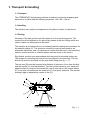
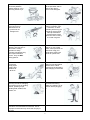
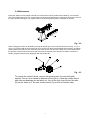
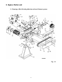
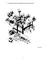
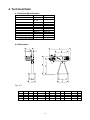
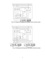
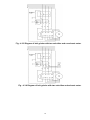
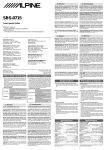
. Operators Manual Belt Grinding Machines Models BG75 – BG150 JEI SOLUTIONS LTD Unit 30, Newhallhey Business Park Rawtenstall Rossendale Lancashire BB4 6HR UK Tel- (00 44) 1706 229490 Fax (00 44) 1706 830496 Email – [email protected] www.steelbeast.co.uk EU declaration of conformity Unit 30, Newhallhey Bus Park Rawtenstall, Rossendale Lancs BB4 8EP UK Hereby declares that SteelBeast Belt Grinding Machine is manufactured in accordance with the provisions of the COUNCIL DIRECTIVE of 17. May 2006 (2006/42/EC) – The Machinery Directive (order no. 561 of 25 June 1994 with subsequent amendments) 2006/42/EC: 2004/108/EC: 2006/95/EC: Directive on machinery-safety Directive on Electromagnetic Compatibility Low Voltage Equipment Safety directive Also on accordance with: The council directive of 19 February 1973 (73/23/EEC) – The Low Voltage Directive – with later amendments (order no. 797 of 30 August 1994) The council directive of 3 May 1989 (89/336/EEC) – The EMC Directive – with later amendments (order no. 796 of 5 December 1991 with subsequent amendments) 2 Table of Contents 1. TRANSPORT & HANDLING 4 1.1 TRANSPORT 1.2 HANDLING 1.3 PLACING 4 4 4 2. DIRECTIONS 5 2.1 OPERATION 2.2 SAFETY RULES FOR STATIONARY POWER TOOLS. 2.3 SAFETY RULES FOR STATIONARY POWER TOOLS. 2.4 MAINTENANCE 3. SPARE PARTS LIST 5 5 5 7 8 3.1 DRAWING OF BELT GRINDING MACHINE WITHOUT EXHAUST SYSTEM 3.2 SPARE PARTS LIST FOR BELT GRINDING MACHINE WITHOUT EXHAUST SYSTEM 3.3 DRAWING FOR BELT GRINDING MACHINE WITH EXHAUST SYSTEM 3.4 SPARE PARTS LIST FOR BELT GRINDING MACHINE WITH EXHAUST SYSTEM 4. TECHNICAL DATA 8 9 10 11 13 4.1 TECHNICAL SPECIFICATIONS 4.2 DIMENSIONS 4.3 CIRCUIT DIAGRAMS 4.4 PRESSUREDIAGRAM 13 13 14 17 5. WARRANTY 18 5.1 GUARANTEE 18 3 1. Transport & Handling 1.1 Transport The STEELBEAST belt grinding machine is packed in protective wrapping and delivered on a pallet with the following measures: 120 x 80 x 120 cm 1.2 Handling The machine can easily be transported on the pallet on which it is delivered. 1.3 Placing Mounting of the belt grinder must take place on a firm and level ground. The machine must be fastened to the ground by means of the four fittings which are used to fasten the belt grinder to the pallet. The machine is provided with no-volt release protection switch and connected for the wanted voltage (V). The electrical connection must be performed by an authorized electrician, and it is important to control that the motor (and ventilator) has the correct direction or rotation (please see the arrow on the motor). Eye shields, suction hose and perhaps dust bag must be mounted before use. The clamps for mounting the suction hose are placed in the dust bag. The eye shields (A) must be mounted into the eye shield fitting (see fig.: 1.1). The tool rest (B) must be mounted at a distance of minimum 2 mm from the belt, and the handle (C) must be fastened. Turn the contact wheel by your hand and adjust the belt by means of the handle (D) until it runs just on the contact wheel (E). It must be controlled that the spark box (F) is properly fastened. The wanted working height is adjusted by means of the (G). Fig.: 1.1 4 2. Directions 2.1 Operation After adjustment and connection the belt grinding machine is ready for use. The grinding can take place by the contact wheel (E) or on the surface grinding table by opening the cover (H). The lifetime of a new belt is prolonged if the grinding starts with a light pressure. 2.2 Safety rules for stationary power tools. Follow them to achieve best results and full benefit from your new machine 2.3 Safety rules for stationary power tools. Follow them to achieve best results and full benefit from your new machine. The good craftsman respects 1. Know your power tool. Read the owner’s manual the tools with which he works. carefully. Learn its applications and limitations, as He knows they represent years well as the specific of constantly improved design. potential hazards He also knows that they are peculiar to this tool. dangerous if misused. This is the theme of a new safeuse program for stationary power tools. The safety rules are based on approved practices in industrial and home shops 2. Keep guard in place and in working order. 3. Ground all tools. If tool is equipped with threeprong plug, it should be plugged into a three-hole electrical receptacle. If an adapter is used to accommodate a twoprong receptacle, the adapter wire must be attached to a known ground. Never remove the third prong. 4. Remove adjusting keys and wrenches. Form habit of checking to see that keys and adjusting wrenches is removed before turning it on. 5. Cluttered areas and benches invite accidents. 6. Avoid dangerous environment. Don’t use power tools in damp or wet locations or expose them to rain. Keep your work area well lighted. 6. Keep children away. All visitors should be kept in a safe distance from work area. 5 8. Make workshop kid proof with padlocks, master switches, or by removing starter keys. 9. Don’t force tool. It will do the job better and be safer at the rate for which it was designed. . 10. Use right tool. Don’t force tool or attachment to do a job it was not designed for. 11. Wear proper apparel. Wear no loose clothing, gloves, neckties, rings, bracelets, or other jewellery which may get caught in moving parts. Non-slip footwear is recommended. Wear protective hair covering to contain long hair. 12. Always use safety glasses. Also use face or dust mask if cutting operation is dusty. Everyday eyeglasses only have impact resistant lenses. They are NOT safety glasses. 13. Secure works. Use a clamps or vice to hold works, when practical. It’s safer than using your hands and it frees both hands to operate tool. 14. Don’t overreach. Keep proper footing and balance at all times. 15. Maintain tools with care. Keep tools sharp and clean for best and safest performance. Follow instructions for lubricating and changing accessories. 16. Disconnect tools before servicing and when changing accessories such as grinding wheels, polishing mops, grinding belts, blades, bits, cutters, etc. 17. Reduce the risk of unintentional starting. Make sure switch is in off position before plugging in. 18. Use recommended accessories. Consult owner’s manual for recommended accessories. Use of improper accessories may cause risk of injury to persons. 6 2.4 Maintenance Empty the spark box with regular intervals and control if the suction canals need a cleaning. The dust bag has to be emptied after use. The contact wheel should be replaced when the edges have been worn round or the tyre has been damaged. The graphite pad on the surface grinding table is changed as required. Fig.: 2.2 When changing the belt it is released by turning the handle (I) in anti-clock-wise direction (see fig.: 2.1), the cover (J) is opened and the worn-down belt (K) is removed by driving the belt against the direction of rotation, and the belt is removed from the machine by the drive wheel. The new belt is fitted. It must be checked that the direction of the arrows on the back side of the belt correspond to the direction of rotation. Fasten the handle (I) again and bring it into alignment with the handle (D). Fig.: 2.3 To change the contact wheel, remove the grinding belt, tool rest and spark arrester. Use a 6 mm mandel to hammer out the pin (L). Now the contact wheel with axle and bearings can be taken out. One of the lock rings (M) and the axle (N) can be taken out. The new contact wheel (O) is fitted in reverse order. 7 3. Spare Parts List 3.1 Drawing of Belt Grinding Machine without Exhaust system Fig.: 3.1 8 3.2 Spare Parts List for Belt Grinding Machine without Exhaust System When ordering spare parts, please state machine type and serial number together with item number and description of the part according to this list. Item No. 1 2 4 5 6 7 8 9 10 15 18 20 21 22 23 24 25 26 27 29 32 35 36 37 39 42 44 47 48 49 50 51 52 53 55 56 57 58 59 60 61 62 64 66 67 68 69 70 71 72 73 78 79 80 88 89 91 97 98 Description Part Number BG75 BG150 0102267 0102267 0239202 0239502 0880002 4532344 0233605 0233705 0233050 0233050 0233207 0233507 0233808 0233808 0300134 0300134 0239373 0239373 0233025 0233025 0300144 0300144 0233221 0233521 0102265 0102265 0110223 0110523 0101224 0101524 0233806 0233806 0233020 0233020 4567832 4567832 0239832 0239832 6549081 6549081 0950614 0950614 1535005 1535007 0331662 0331662 0928644 0928644 0188845 0188845 0188892 0188892 0188893 0188893 0102266 0102266 0860327 0860327 0101491 0101491 2323212 2323212 5437850 5437850 0100425 0100425 0951406 0951406 0921475 0921475 6540981 6540981 0311262 0311262 0233251 0233551 0915720 0915720 1055860 1055860 0930612 0930612 0102268 0102268 0752262 0752262 6540981 6540981 0737620 0737620 0737631 0737631 0110089 0110089 0105167 0105167 0233807 0233807 1055680 1055682 Belt Release Handle Belt guard Grinding stop / Cover Blue Eye shield Split pin ø6x50 mm Tool rest Handle for tool rest Bolt M10x25 Support for tool rest Handle M6x25 Fan cover for motor Screw M8x12 Graphite pad Spring 5,5x43x125x11 mm Cradle for contact wheel Spark arrester Star Handle Ø32 M6x16 Screw M8x20 Bolt M12x100 Drive wheel Base without exhaust system Side panel Grinding belt Screw M6x45 CH Fan wheel for motor Contact wheel with bearings Ball handle M6xØ25 Lock nut M8 Switch comp. Brake Module (Additional) Thermo relay Emergency stop comp. Relay w/0-volt release coil Start/stop protection cover Split pin Ø4x50 mm Disc 10x45x4 Disc 10mm Disc 10mm Disc 8mm Screw M4x8 Lock nut M6 Hinge mounting for eye shields Disc 8mm Lock ring Ø20 Shaft Lock ring Ø7 Rubber list 657 mm Screw M6x12 Wave spring 14x0.3x21 Eccentric for 8 mm motor sheet Disc 8mm Screw M4x5 Motor Parallel key Disc 6mm Screw M6x10 Disc 8mm Star M6 Rest for surface grinding 9 3.3 Drawing for Belt Grinding Machine with Exhaust System Fig.: 3.2 10 3.4 Spare parts List for Belt Grinding Machine with Exhaust System When ordering spare parts please state machine type and serial number together with item number and description of the part according to this list. Item No. Description 1 2 4 5 6 7 8 9 10 11 13 14 15 16 17 18 20 21 22 23 25 26 27 29 33 35 36 37 38 39 41 42 44 47 50 51 52 53 55 56 57 58 59 60 61 62 64 66 67 68 69 70 71 72 73 77 78 79 80 81 82 83 84 85 86 88 89 91 Belt release handle Belt guard Grinding stop/Cover Blue Eye shield Split pin ø6x50 mm Tool rest Handle for tool rest Screw M10x25 Support for tool rest Suction hose ø63 Fan cover for exhaust motor Dust bag Handle M6x25 Lock nut M12 Cable Fan cover for motor Screw M8x12 Graphite pad Spring 5,5x43x125x11 mm Fork for contact wheel Star handle Ø32 M6x16 Screw M8x20 Bolt M12x100 Drive wheel Hose strap 58-75 mm Side plate for GRIMAX Grinding belt Screw M6x45 CH Dust extractor Fan wheel for motor Fan wheel for exhaust motor Contact wheel with ball bearings Ball handle M6xØ25 Lock nut M8 Thermo relay Emergency stop comp. Relay w/0-volt release coil Start/stop protection Split pin Ø4x50 mm Disc 10x45x4 Disc 10mm Disc 10mm Disc 8mm Screw M4x8 Lock nut M6 Hinge mounting for eye shields Disc 8mm Lock ring Ø20 Shaft Lock ring Ø7 Rubber strip 657 mm Screw M6x12 Wave spring 14x0.3x21 Eccentric for 8 mm motor sheet Disc 8mm Parallel key 36x6x6 Screw M4x5 Motor Parallel key Screw M4x12 Cover for terminal box Exhaust motor 0.5HP Fan wheel large 250 mm Disc 5mm Screw M5x30 Disc 6mm Screw M6x10 Disc 12mm Part Number BG75X BG150X 0102267 0102267 0239202 0239502 0880002 4532344 0233605 0233705 0233050 0233050 0233207 0233507 0233808 0233808 0300134 0300134 0104373 0104373 7891011 7891011 2075180 2075180 0811793 0811793 0233025 0233025 0105166 0105166 0963084 0963084 0300144 0300144 0233221 0233521 0102265 0102265 0101224 0101524 0233806 0233806 0233020 0233020 4567832 4567832 0233058 0233058 6549081 6549081 0950614 0950614 0239853 0239853 2031015 2031015 1535005 1535007 0331662 0331662 0928644 0928644 0188892 0188892 0188893 0188893 3454351 3454351 0860327 0860327 0101491 0101491 2323212 2323212 5437850 5437850 0100425 0100425 0951406 0951406 0921475 0921475 6540981 6540981 0311262 0311262 0233251 0233551 0915720 0915720 1055860 1055860 0930612 0930612 0102268 0102268 0752262 0752262 6540981 6540981 0110077 0110077 0737620 0737620 0737610 0737610 0110082 0110082 2030040 2030040 0995704 0995704 0233030 0233030 0331786 0331786 0737631 0737631 0110089 0110089 0105167 0105167 11 93 94 96 97 98 99 Screw Taptite M6x16 Side plate for base Spark box with exhaust system Star M6 Rest for surface grinding Switch comp. 0910616 0239128 0239252 0233807 1055680 - 12 0910616 0239128 0239552 0233807 1055682 - 4. Technical Data 4.1 Technical Specifications Model Grinding belt BG75/75X Motor 3x380-440 V 50 Hz * Class IP Class R/min. Amp Cos Belt speed (m/s) Contact wheel Grinding surface Fan motor (only X-model) Weight without fan/with fan 75x2000 4,1 HK 4,8 HK IEC 34-1 54 2800 10.6/6.1 0,91 30 Ø200x75 540 mm 0,5 HK 85 kg /111 kg BG150/150X 150x2000 4,8 HK * IEC 34-1 54 2800 10.6/6.1 0,91 30 Ø200x150 540 mm 0,5 HK 114 kg /140 kg * 5,5 HP motor available. 4.2 Dimensions Fig.: 4.2 Model 50 75 100 150 A 995 995 995 995 B 660 660 660 660 C 890 890 890 890 D 780-1070 780-1070 780-1070 780-1070 13 E 420 420 420 420 F 506 506 506 506 G 255 255 255 255 H 341 341 341 341 I 392 413 439 491 J 306 306 306 306 K 86 107 133 185 4.3 Circuit diagrams STEELBEAST belt grinding machines can be connected to 3 x 400/440 V, 50/60 cycles and to 3 x 230 V 50/60 cycles. There are three kinds of circuit diagrams: 1. One velocity grinder without brakes see 4.3.1 and 4.3.2 2. One velocity grinder with brakes see 4.3.3 and 4.3.4 3. Two velocity grinder with no brakes see 4.3.5 and 4.3.6 Fig. 4.3.1.: Diagram of belt grinder with no exhaust motor. Fig. 4.3.2.: Diagram of belt grinder with exhaust motor. 14 Fig.: 4.3.3 Diagram of belt grinder with brake and no exhaust motor. Fig.: 4.3.4 Diagram of belt grinder with brake and exhaust motor. 15 Fig.: 4.3.5 Diagram of belt grinder with two velocities and no exhaust motor. Fig.: 4.3.6 Diagram of belt grinder with two velocities and exhaust motor. 16 4.4 Pressure diagram The fan is especially developed for belt grinders. It can set up a pressure up to 1300 Pa and an air flow from 0 to 650 m³/hour. It is constructed of 1,5 mm steel plate and is spot welded. It has a 3-phase motor 3x230/400 V and 1x230V 50/60 Hz, 2800 RPM. The fan is enclosed in Class IP 54. 17 5. Warranty 5.1 Guarantee If within 2 year of purchase this machine supplied by JEI Solutions Ltd becomes defective due to faulty materials or workmanship we guarantee to repair or replace the machine or defective part or parts free of charge provided that: 1. The product is returned complete to one of our Service Branches or Official Service Agents. 2. The product has not been misused or carelessly handled and in particular has not been used in a manner contrary to the operating instructions. 3. Repairs have not been made or attempted by other than our own Service Staff or the staff of our Official Service Agents. 4. Documentary proof of purchase date is produced when the goods are handed in or sent for repair. 5. Wear parts are not covered by the warranty JEI Solutions Ltd offers you five years guarantee on the electrical motor if the motor becomes defective or even burns-out within the first 5 years from date of invoice. JEI SOLUTIONS LTD Unit 30, Newhallhey Business Park Rawtenstall Rossendale Lancashire BB4 6HR UK Tel- (00 44) 1706 229490 Fax (00 44) 1706 830496 Email – [email protected] www.steelbeast.co.uk 18