1
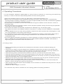
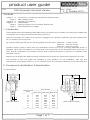
product user guide
Title
Issue
EMV Excavator Mounted Vibrator
2
Date
October 2013
Contents
Pages 1 Page
Pages 4 Pages 5 Page
Page
2
3
5
6
6
7
:
:
:
:
:
:
Introduction, Component Identification & Specification
Basic Safety Points
Operating Procedures
Maintenance
Fitting the EMV to the Excavator, References
EMV Maintenance Images
1. Introduction
The Excavator Mounted Vibrator (EMV) attachment is a perfect tool for readily converting any suitable size
of excavator into a highly productive pile driving machine.
Piles can be lifted from a stack on the ground, engaged into a powerful hydraulic grip then positioned at
will, for vibrating into the ground.
As a guide, EMVs typically suit the following base machine sizes - EMV 220 - 7 to 22 tonnes
EMV 300 - 12 to 25 tonnes
EMV 400 - 25 to 45 tonnes
Hydraulic power supply is taken from the excavators’ bucket ram circuit, providing adequate power is
available. Other than the addition of a small drain line directly back to the excavators tank, there are no
other special modifications to the base machine and no electrical system is required. The operator uses
standard controls.
Maximum pile lengths are determined by excavator boom length but typical pile lengths are up to 6m.
The contents of this user guide are intended to give guidance on the installation, safe use and
maintenance of the EMV product. It is not intended to be an exhaustive detailing of the manufacturers
2. Component Identification & Specification
2.1 Identification
E
F
D
Dimensions
(mm)
H
C
(Min. Pile Width)
A
B
C
D
E
F
G
H
EMV Model
EMV 220 EMV 300 EMV 400
445
40
150
431
431
850
1120
130
615
25
250
582
429
927
1200
150
Page 1 of 7
615
32
230
640
510
945
1250
175
B
(Max. Pile Thickness)
G
A
product user guide
Title
EMV Excavator Mounted Vibrator
Issue
2
Date
October 2013
2.1 Identification cont’d
Lifting Chain c/w Chain Clamp
Code: EMVC01 & EMVC01A
(issued with a current Report of
Thorough Examination)
EMV Stand
Weight: 116 kg
No code no.
Universal Bracket
Weight: 51 kg
Code: EMV-D-SB
Large Quickhitch Bracket
Weight: 180 kg
Code: EMV-D-LQHB
Standard Quickhitch Bracket
Weight: 110 kg
Code: EMV-D-QHB
Notes:
2.1.1 Each EMV has its own unique Item Number
2.1.2 Product codes EMV-220, EMV-300 and EMV-60030 include a Universal Bracket and Stand.
A Quickhitch Bracket can be supplied upon request.
2.1.3 Lifting chains and Chain Clamps have individual item numbers and are booked out separately,
but are attached to the EMV.
2.1.4 If a Large Quickhitch Bracket is required due to the machine size, it is fitted directly to the EMV.
The Large Quickhitch Bracket is complete with a Universal type bracket.
2.2 Specification
Specification
EMV Model
EMV 220
Static Moment (kgm)
Frequency (vpm)
Centrifugal Force (kN)
Amplitude - peak to peak (mm)
Minimum Required Flow Rate (l/min)
Maximum Allowable Flow Rate (l/min)
Minimum Hydraulic Pressure (bar)
Maximum Hydraulic Pressure (bar)
Minimum Hydraulic Power (kW)
Dynamic Mass (kg)
Total Mass (kg)
Maximum Pile Mass (kg)
Maximum Push/Pull Loading (kg)
Clamp Force (tonne)
Page 2 of 7
3.24
3000
220
12
90
250
280
350
42
370
525
800
7500
26.5
EMV 300
4.6
2400
300
14.7
130
250
280
350
60
625
965
800
15000
36
EMV 400
6.9
2460
450
12
195
350
270
350
88
1008
1275
1000
15000
54
product user guide
Title
EMV Excavator Mounted Vibrator
Issue
2
Date
October 2013
3. Basic Safety Points
•
•
•
•
•
•
•
•
•
•
•
The vibrator should only be operated by suitably qualified personnel.
There should be visual contact between operator and slinger (spotter) at all times.
Monitor the piling operation constantly - interrupt the process immediately if any danger occurs.
Do not operate the vibrator if any person is within a 15m radius of the unit.
Consider machine stability at all times.
The operator should inspect the equipment for defects every day and before being taken into service.
Any defects that affect operational safety should be corrected before the equipment is taken into
service - see section 5.
Pay attention to the Safe Working Load of all lifting accessories at all times.
The working area should be properly illuminated.
Work safely at all times and within the requirements of all local legislation.
The vibrator can become very hot during operation - do not touch it unless wearing appropriate
protective clothing.
The maximum weight of pile that can be used with the EMV220 & EMV300 = 800kg & with the
EMV400 = 1000kg.
3.1 Who is Responsible?
Those who are in charge of, or responsible for, the use and maintenance must ensure that the vibrator
and all it's auxiliary equipment are in good condition.
Piling should only be carried out under the supervision of an appropriately qualified and experienced
person who can assess that the work is carried out safely.
The excavator operator must ensure that his communication signals are understood, by those on the
ground, and followed. During piling operations he must watch out for any potential hazards.
3.1.1 Working Conditions
Vibrators should only be operated and driven on firm ground with clear visibility of the working
area and the process monitored constantly.
The vibrator stand must stay upright and horizontal (at all times) to avoid personnel injury. Do
not operate the vibrator if any personnel are within a 15m radius of unit . Personnel are at risk
when within this area from:
•
•
•
•
•
Falling piles - should the pile be handled incorrectly
Liquids under high pressure and associated components
Mechanical failures of equipment components
Noise - wear ear protection equipment when inside this area
Unexpected overturning of the excavator
3.1.2 Working near Underground Obstacles
Before the start of any piling work it is the customers responsibility to find out if there are any
underground obstacles within the working area which could be dangerous to personnel. In the
case of unforeseeable contact or damage of an underground obstacle, then work must stop
immediately and the person in charge informed.
3.2 Transporting the Vibrator
When transporting the vibrator, ensure it is placed correctly in the stand. Once in place on the stand, the
jaws must be closed. Release the hydraulic hoses from the excavator (the hard jaws will remain closed)
and cap the hose ends to prevent contamination. Disconnect the vibrator from the excavator.
3.3 Transporting Piles on Site
Transporting a pile using the vibrator should only be done over a short distance, with the clamp fully
engaged on the pile top and with the safety chain fitted. Should the grip on the pile be reduced during
this procedure, the excavator must stop, and a better grip effected. Should a pile slip then the lifting
chain could snap and cause an accident. When transporting a pile extreme care must be taken to
ensure that no one is in the Danger Area and that the pile is handled in such a way as to ensure no
danger to site personnel at any time. Care should be taken at all times to ensure the safety chain does
not become snagged in the jaws of the EMV.
In order to avoid extensive transporting, have the piles laid out as close to the point of installation as
possible. Do not use the excavator with the EMV installed to handle bundles of piles around the job site.
Page 3 of 7
product user guide
Title
EMV Excavator Mounted Vibrator
Issue
2
Date
October 2013
4. Operating Procedures
It is the excavator operator's responsibility to ensure that the machine is functioning and performing
correctly. In order to meet this responsibility please note the following points:
• Allow the excavator engine to warm up, particularly in temperatures below 10°C.
• Before work commences, slowly operate the bucket arm lever in both directions. It is particularly
important that the vibrator is allowed to run freely for approximately 30 seconds, this allows the gearbox
oil to reach all the necessary lubricating points.
• Screws, bolts, connections, etc are often loosened through the vibration of the machine. Check for
looseness daily.
• Pay daily attention to the general condition of the hard jaws (vibrator clamp). Ensure they are replaced
once signs of wear are apparent.
• Check both the vibrator and auxiliary equipment for damage. E.g. On the lifting chain.
Any defects should be immediately notified to the person in charge. DO NOT OPERATE A DAMAGED
UNIT.
• It will be apparent from the noise during vibration whether the clamp cylinder has closed tightly. If it has
not, check operation of the clamp off the pile top.
• It is imperative that you ensure that during a piling operation the vibrator is kept directly above and in
line with the pile, otherwise the piling energy is transferred to the excavator arm and causes
unnecessary wear.
• If the pile reaches premature refusal then it will be necessary to loosen up the ground, possibly through
drilling. UNDER NO CIRCUMSTANCES SHOULD THE PILE BE FORCED FURTHER. Alternatively a
larger piling device should be used. See Section 4.3
4.1 Putting In Piles
• Ensure that all safety procedures and maintenance have been carried out before starting the
excavator.
• Check that it is safe to move the dipper arm. Release the stand from the jaws of the vibrator and
manoeuvre the vibrator above one end of the pile to be pitched so that there is enough distance to
allow safe insertion of the lifting chain through the hole at the top of the pile.
• Insert the lifting chain correctly (without twists or knots etc.) and secure with the chain clamp.
• Clear all personnel standing in the working area and lift up the pile until it hangs freely off the ground.
• Lower the pile slowly so that it can be correctly inserted into the clamp. Once firmly inserted close the
jaws. Ensure safety chain is not snagged in EMV.
• Manoeuvre the pile to its insertion point and push the pile slowly into the ground. Plumb the pile and
ENSURE THAT ALL PERSONNEL ARE OUT OF THE WORKING AREA.
• Start the vibrator and adjust (crowd) the hydraulic rams so that the vibrator is level and always sits
directly on top of the pile as it goes into the ground.
• When the pile has reached the required depth turn the vibrator off. Release the hard jaws from the pile.
Remove lifting chain.
• Repeat the above stages to continue.
The customer may want to consider the use of piling guides to aid piling operations.
Page 4 of 7
product user guide
Title
EMV Excavator Mounted Vibrator
Issue
2
Date
October 2013
4.2 Taking Out Piles
• Ensure that all safety procedures and maintenance have been carried out before starting the
excavator.
• Check that it is safe to remove the dipper arm. Release the stand from the jaws of the vibrator.
Manoeuvre the vibrator above the pile so that there is sufficient lifting chain to go through the hole at
the top of the pile.
• Insert the lifting chain correctly (without twists or knots) and secure with the chain clamp. UNDER NO
CIRCUMSTANCES SHOULD A PILE BE PULLED USING THE LIFTING CHAIN ONLY.
• Clamp the vibrator onto the pile head ensuring that it is level. ENSURE THAT ALL PERSONNEL
ARE OUT OF THE WORKING AREA.
• Start the vibrator and allow the soil to loosen around the pile. Start to lift up the pile and ensure that
the pile clutches are not rubbing together. Pay attention to the distortion of the rubber sandwich
mounts - UNDER NO CIRCUMSTANCES SHOULD THE DISTORTION EXCEED 30mm.
• After removing the pile, turn the vibrator off. Move the pile to a suitable area and place it on the
ground. ENSURE THAT ALL PERSONNEL ARE OUT OF THE WORKING AREA.
• Hold the pile on the ground and release the jaws. Raise the vibrator off the pile slowly, ensuring that
there is no snatch on the lifting chain. Slowly lower the pile towards the ground. Remove the lifting
chain.
• Repeat the above stages to continue.
4.3 Piling Refusal & Rebound
As with all machinery, there is a limit to the operational conditions under which the machinery is
expected to operate. For vibratory driving, The Shoring Technology Interest Group (STIG) defines these
limit conditions for REFUSAL and REBOUND as follows:REFUSAL – under normal conditions, refusal is defined when the time taken to drive a pile 250mm,
exceeds 5 minutes. The penetration distance of 250mm is absolute, i.e. No conversion is allowed, for
instance, 20 minutes for 1m penetration
REBOUND – This occurs when a large proportion of the EMVs energy is reflected back up through the
pile as a result of hitting an impenetrable layer or obstruction. The reflected forces will be transferred
back into the EMV and the suppressor head, and as a result, the head will start “jumping” relative to the
vibratory case.
In this situation driving should be stopped immediately.
5. Maintenance
The Excavator Mounted Vibrators have been designed to give years of trouble free service. Providing
the equipment is treated with respect and the basic maintenance procedures are adhered to there will
be little additional work required.
Visual inspection of the EMV by a competent person on a daily basis and before being taken into
service can prevent many potential problems from occurring. Ensure that lifting accessory test
certificates are correct and valid at all times.
• All service and maintenance work must be carried out by Mabey Hire Ltd only.
• The equipment should be inspected at ground level only and should be positioned so as to be stable
at all times.
• Secure the equipment against unexpected starting during the daily maintenance process.
Page 5 of 7
product user guide
Title
EMV Excavator Mounted Vibrator
Issue
2
Date
October 2013
5.1 Daily Maintenance - Refer to images on Page 7 for additional details
• Grease the two grease points on the EMV - one on the Saddle Swivel and the other on the side of
the Clamp Body. Two or three pumps with a molybdenum-based grease will be adequate.
• Check visible screws, bolts, fittings etc for tightness.
• Visually inspect all hydraulic hoses and fittings for leaks or damage.
• Check the gear oil level in the vibrator. The level must be halfway up the sight glass.
• Inspect the lifting chain and chain clamp for damage. The chain should be in good order, free from
any structural damage or permanent deformation of any kind. The chain clamp should also be free
from any structural damage and its correct operation and safe function should be checked by
depressing and releasing several times - any binding or hesitancy with its operation should result in
it being changed for a new certified item. The chains coupler and anchorage point should be in
good order showing no signs of damage, wear or cracking. Remember – If in doubt, contact Mabey
Hire Ltd.
• Inspect the condition of the Hard Jaws. To be acceptable these should look to be in almost as new
condition. The teeth on these pads have some flats on them when new (approx. 1.5 x 1.5mm).
Over time they will round off, flatten out more and even become chipped. If not changed when
required they will loose their grip on the pile during driving and certainly during extraction. Besides
causing a reduction in performance this can become a safety hazard. We define the following wear
limit:
Hard Jaw Wear Limit - 90% of all teeth on any hard jaw should make contact with the pile and 80%
of all teeth should have points with flats no greater than 5x5mm.
• Inspect the rubber Sandwich Mounts (Elastomers) for wear or damage. Wear is typified by
splitting/tears. This usually occurs in the rubber adjacent to the bonded steel plates and is usually a
result of fatigue in the material over a long period of time. Crazing/softening may occur but this is
usually associated with long term exposure to sunlight or exposure to petroleum based products.
As a general rule change the Sandwich Mount if any single tear or split exceeds 40mm or if the
rubber has become contaminated.
• Check the overall condition of the Swivel Assembly. Check that the Lifting Bolt and Nut (that are the
centre piece of this assembly) only allow rotational movement with minimal axial movement.
Excessive axial movement will allow the assembly to rattle around, make more noise and cause in
turn more wear. If the axial play exceeds 1mm then DO NOT USE - contact Mabey Hire Ltd
immediately.
• Check the condition of the Boom Adaptor Bracket, Shear Pins, Spacers and Bushes. The whole
assembly should be relatively tight with minimal play in the components. The bracket needs to be
able to float a little from side to side - as much as 5/10 mm is acceptable. The pins and bushes
should however be little more than a running fit - clearances of more than 0.5mm would be
considered excessive.
6. Fitting the EMV to the Excavator
Fitting the EMV to the excavator should only be carried out by a Mabey Hire Ltd employee. Incorrect
installation can result in expensive damage to both EMV and excavator.
7. References
Shoring Technology Interest Group (STIG) - ‘Safety in Shoring’
BS EN 996: 1995 + A3 - Piling Equipment - Safety Requirements
Page 6 of 7
product user guide
Title
EMV Excavator Mounted Vibrator
Issue
2
Date
October 2013
Saddle
Swivel
A
Assembly
Gear Box
Oil Sight
Glass
Lifting Chain
&
Chain Clamp
Hard Jaws
Clamp Body
Grease Point for the
Moving Jaw
Page 7 of 7