1
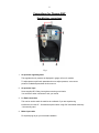
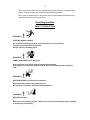
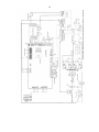
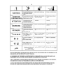
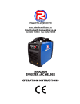
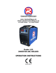
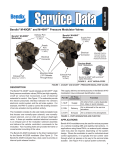
www.r-techwelding.co.uk
PLASMA 40HF INVERTER PLASMA CUTTER
OPERATION INSTRUCTIONS
www.r-techwelding.co.uk
Tel: 01452 733933
2
3
Thank you for selecting the R-Tech Plasma 40HF Inverter Plasma Cutter
The Plasma 40HF has many benefits over traditional transformer plasma cutters,
including infinite power control, HF pilot start and HF pilot restart which is ideal for cutting
mesh etc , quick fitting cost effective torch, long life cost effective torch consumables and
a 60% industrial duty cycle
We want you to take pride in operating our Plasma 40HF as much pride as we have taken
in making this product for you. Please read all information in this manual before operation
PLEASE EXAMINE THE CARTON AND EQUIPMENT FOR DAMAGE IMMEDIATELY
When this equipment is shipped, title passes to the purchaser upon receipt from the courier.
Consequently all claims for material damaged in shipment must be made by purchaser against
the transportation company used.
Please record your equipment identification below for future reference. This information can be
found on the data plate at rear of machine.
Product: Plasma 40HF
Serial No. ___________________________________
Date of Purchase _____________________________
Where Purchased _____________________________
Whenever you request replacement parts or information on this equipment please always
supply information you have recorded above.
This product is covered by a 2 year parts and labour warranty; we will cover cost of collecting and
returning the item to you. External items, (torch, earth lead etc…) are covered by a 3 month warranty. Any
faults/damage found caused by a customer will be charged accordingly.
Pay particular attention to the safety instructions we have provided you for your protection
The level of seriousness to be applied to each section is explained below
WARNING
This statement appears where the information must be followed exactly to avoid serious personal injury.
CAUTION
This statement appears where the information must be following to avoid a minor personal injury or damage
to this equipment.
4
Introduction
The R-Tech Plasma 40HF is a member of our field acclaimed family of welding products.
Premium features include:1. Inverter power source – more efficient to operate, provides smoother weld
characteristics.
2. Infinite cutting power adjustment, allows fine tuning of cut characteristics
3. HF Pilot start – Enables easy arc start even on painted surfaces
4. HF pilot arc restart – ideal for cutting mesh etc
5. Digital amp meters
6. Quick fitting torch for easy torch fitment/replacement
7. Long life – Low cost torch consumables
8. 60% Duty cycle at 40 Amps @ 40ºC
Recommended Processes
The R-Tech Plasma 40HF is recommended for the plasma cutting processes within its output
capacity of 40 Amps DC
Equipment Limitations
The R-Tech Plasma 40HF is protected from overloads beyond the output ratings and duty cycle
as per machine specifications with thermostat protection of the output coils and rectifiers.
Cutting Capability – Duty Cycle
The R-Tech Plasma 40HF is rated at 40 Amps at 60% duty cycle on a ten minute basis. If the
duty cycle is exceeded a thermal protector will shut machine off until the machine cools.
Technical Specifications
MODEL
PLASMA 40HF
Power Voltage
220/240V 50/60Hz
Input Current
28A
Rated Output Current
40A
Current Adjusting Range
20-40A
No-load Voltage
200V
Rated Duty Cycle
60%
Working Mode
HF Start
Air Pressure
50 PSI
Max. Cutting Thickness (Clean cut mild steel)
12mm
Max. Cutting Thickness (Severance cut mild steel)
16mm
After Flow Time
10 Seconds
Dimensions
390 X 190 X 290
5
Safety Precautions
Read entire section before starting installation
WARNING!
Electric Shock can kill – Only qualified personnel should perform this installation. Turn off input
power at the fuse box before working on this equipment. Do not touch electrically live parts.
Always connect the machine to an earthed mains supply as per national recommended
standards.
Select suitable location
Place the plasma cutter where clean cooling air can freely circulate in and out of the front & rear
louver vents. Dirt, dust or any foreign material that can be drawn through vents into plasma cutter
must be kept to a minimum. Failure to observe these precautions can result in excessive
operating temperatures which can lead to plant failure.
Grinding
Do not direct grinding particles towards the plasma cutter. An abundance of conductive material
can cause plant failure.
Stacking
This machine cannot be stacked.
Transport – Unloading
Never underestimate the weight of equipment, never move or leave suspended in the air above
people. Use recommended lifting equipment at all times.
WARNING!
Falling Equipment can cause injury. Never lift plasma cutter with gas bottle attached. Never lift
above personnel.
Tilting
Machine must be placed on a secure level surface or on a recommended undercarriage/trolley.
This machine may topple over if this procedure is not followed.
Environmental Rating
The plasma power source carries the IP21S rating. It may be used in normal industrial and
commercial environments. Avoid using in areas where water / rain is around.
6
Electrical Installation
WARNING!
ELECTRIC SHOCK CAN KILL
Machine grounding and High Frequency Interference Protection
This plasma cutter must be grounded to earth. See national electrical codes fro proper grounding
methods.
The high frequency generator being similar to a radio transmitter may cause interference to radio,
TV and other electronic equipment. These problems may be the result of radiated interference.
Proper grounding methods can reduce or eliminate this.
Radiated interference can develop in the following ways
1. Direct interference from welder power source
2. Direct interference from the welding leads
3. Direct interference radiated from feedback into power lines
4. Interference from re-radiation by un-grounded metallic objects.
Keeping these contributing factors in mind, installing equipment as per following instructions
should minimize problems.
1. Keep the welder input power lines as short as possible and enclose as much of them as
possible in metal conduit or equivalent shielding. There should be a good electrical
contact between this conduit and ground (Earth).
2. Keep the work and electrode leads as short as possible. Tape the leads together where
practical.
3. Be sure the torch and earth leads rubber coverings are free from cuts and cracks that
allow welding power leakage
4. Keep earth lead connection to work in good condition – Clean area on workbench where
earth clamp is situated on a regular basis.
Input Connections
Make sure the voltage, phase and frequency of input power is as specified on machine rating
plate located at rear of machine.
Have a qualified electrician provide suitable input power as per national electrical codes. Make
sure machine is earthed / grounded.
Make sure fuse or circuit breaker is correct rating for machine. Using fuses or circuit breakers
7
smaller than recommended will result in ‘nuisance’ shut off from welder inrush currents even if
cutting at low amperages.
Failure to follow these instructions can cause immediate failure within the welder and void
machines warranty.
Turn the input power OFF at the mains switch & fuse box before working on this equipment.
Have a qualified electrician install & service this equipment.
Allow machine to sit for 5 minutes minimum to allow the power capacitors to discharge before
working inside this equipment. Do not touch electrically live parts
The Plasma 40HF Plasma Cutters require a 240V 50/60Hz 1-Phase supply. It requires an 32A
supply. It comes with a 3 metre mains cable attached.
Connect wires according to national coding.
Brown wire – Live
Blue wire – Neutral
Green/Yellow Wire – Earth (Ground)
Connecting to a mains electrical supply
THIS MACHINE IS OF AN INDUSTRIAL SPECIFICATION AND MUST BE
FITTED TO A 32AMP 240V MAINS INPUT
DO NOT RUN ON 13AMP PLUG – FAILURE TO RUN ON CORRECT SUPPLY
WILL IN-VALIDATE WARRANTY
Connecting to an Engine Driven Generator
If connecting this Plasma Cutter to an engine driven generator please
ensure the following
Minimum Generator KVA Output – 8KVA continuous
Generator to be fitted with AVR (automatic voltage regulation)
DO NOT USE ON A GENERATOR WITHOUT AVR
Connecting to a generator without the above minimum requirements will invalidate your warranty.
8
Connections for Plasma 40HF
Rear Machine connections
Fig 1
1. Air pressure regulating knob
This regulates the air pressure as displayed in gauge on front of machine.
To adjust pressure pull knob upwards and turn to adjust pressure, once correct
pressure is obtained press down knob to secure.
2. Air pressure input
Screw supplied PCL fitting into regulator ensuring no air leaks
You can also fit other connectors to suit your needs
3. 2nd Earth connection
This can be used to earth the machine to workbench if you are experiencing
interference from the HF – Sometimes required when using CNC automated machinery
- Not normally used
4. Mains input cable
Fit required plug as per your electrical installation
9
5. POWER On/Off Switch
Turns machine on and off, the switch illuminates when machine turn on
Front machine connections
Fig 2
1.
Earth / Workpiece connector
Connect the earth lead (negative - ) to this connector. Insert male connector into socket and
twist clockwise until tight. Secure other end of earth lead to Workpiece via the earth clamp.
2.
FUSE
pilotarc fuse
3.
Torch switch socket
Connect the torch switch plug (4 pin) and screw on retaining ring to secure
4.
Pilot lead connector
Connect the ring terminal from torch. Un-screw retainer, fit ring terminal onto shaft and refit retainer
ensuring it is tight
5.
Torch power connector
Connect the main torch cable by screw clockwise until tight.
10
Controls and Settings
4
1
3
2
Fig 1
5
1. Air pressure gauge
This shows the air pressure as set by regulator at rear of machine.
This should be set to 50PSI when the test gas button is activated.
2. Amperage control knob
This adjusts the amperage (cutting power) from 20 to 40 amps
Note: LED display will show cutting amperage when you are cutting
3. L.E.D amperage display
When cutting this shows the actual cutting amperage
4. Test Gas / Cutting selector switch
When in the up position this is test gas mode, when setting air pressure switch to test gas so you
obtain actual air flow cutting pressure
When in the down position this is cutting mode, you can now start cutting
5. Auto / Standard switch
When in the down position this is in standard cutting mode, this is the normal operating position for
plasma cutting with a hand held and machine type torch
When in the up position this is in auto mode, this is for special applications when using automated
machinery. Not normally used
11
When in the down position this is in standard cutting mode, this is the normal operating
position for plasma cutting with a hand held and machine type torch
When in the up position this is in auto mode, this is for special applications when using
automated machinery. Not normally used
Operating machine
SAFETY PRECAUTIONS
WARNING!
ELECTRIC SHOCK CAN KILL
Do not touch electrically live parts or electrode with skin or wet clothing.
Insulate yourself from work and ground
Always wear dry insulating gloves
WARNING!
FUMES AND GASES can be dangerous
Keep your head out of fumes & gases produced from welding.
Use ventilation or exhaust to remove fumes & gases from breathing zone and general
area.
WARNING!
WELDING SPARKS can cause fire or explosion
Keep flammable material away from work area.
Do not weld on containers that have held combustibles
WARNING!
ARC RAYS can burn
Wear eye, ear and body protection – Make sure work area is protected by proper shielding
to avoid injury to passers by.
12
Operating Machine
Please ensure all torch consumables are tight before use
1. Ensure machine has been setup as previously stated
2. Turn on the machine and the power light indicates and cooling fan is running
3. Set the function switch in the ‘test gas’ position, air will flow from torch head, now set the
air pressure in gauge using adjuster on regulator on rear of machine to 50PSI
Once the correct air pressure has been set press down the adjuster on air regulator and
set the function switch to the ‘cutting’ position
4. Ensure earth clamp is connected to workpiece or workbench ensuring a good clean point
of contact
5. Select cutting amperage knob to desired cutting power (the following guide lines will vary
in accordance to material grade, characteristics and user operation)
20 Amps for up to 6mm on mild steel
30 Amps for up to 9mm on mild steel
40 Amps for up to 12mm on mild steel
When cutting aluminium, alloys and stainless steel cutting thickness is reduced by
approximately 20%
6. Hold torch in starting position on work and press torch switch and the pilot arc will initiate
(blue flame from torch) , once the pilot arc is in contact with the workpiece it will sense
this and switch to main cutting power.
Once you come to the end of cut/workpiece the machine will sense this and turn off main
cutting power and re-start the pilot arc. If you have now finished cutting release torch
trigger and pilot arc will stop. Air will continue to flow from torch for a preset time to cool
torch consumables.
7. Getting correct amperage / cutting speed for desired job.
The combination of correct cutting amperage and travel speed can change per user, here
are some tips on obtaining optimum settings.
Blow back when cutting – If you experience blow back and the metal is not cut all the way
through, you either are traveling too fast or you need to increase the cutting amperage
Cutting arc is erratic and work is being cut all way through. You are traveling too slow or
cutting with too high amperage for work. What is happening is the machine is sensing
that there is no metal left to cut and turning off main cutting power and going back to pilot
arc mode and when you move again it senses more metal to cut and brings main cutting
power back in.
13
It can take a while to get used to plasma cutting if never done before. Experiment with
settings on some scrap material until you find the best amperage / cutting speed for user.
If you ever have any questions on settings call us and speak to one of our experienced
technicians who will be happy to help you.
Replacing torch consumables
WARNING!
ELECTRIC SHOCK CAN KILL
Please ensure machine is turned off before changing consumables
If cutting performance is poor you probably need to check / change the torch consumables.
To change the plasma cutting consumables carry out the following procedure
1.
Switch off machine
2.
Ensure torch has cooled down to avoid burns
3.
Unscrew the pink ceramic shroud
4.
Remove the silver cutting tip
5.
Check the condition of cutting electrode, replace cutting electrode if tip is worn 1-2 mm and
end is concave
6.
Fit new cutting electrode by screwing in and tweaking with pair of pliers – Do not over
tighten as this will cause thread / torch head damage
7.
Fit new cutting tip by screwing in and tweaking with a pair of pliers – Do not over tighten as
this will cause thread / torch head damage
8.
Refit pink ceramic cup by screwing on hand tight
9.
Turn machine back on and continue cutting
14
Maintenance
Routine and periodic maintenance
WARNING!
ELECTRIC SHOCK CAN KILL
Turn the input power OFF at the mains switch & fuse box and remove mains plug from socket
before working on this equipment.
Have a qualified electrician install & service this Plasma cutting equipment.
Allow machine to sit for 5 minutes minimum after disconnection from mains power to allow the
power capacitors to discharge before working inside this equipment.
Do not touch electrically live parts
1. Periodically (3-6 months depending on use / environment), remove the side/top panels of
machine and clean out machine with a low pressure dry air line paying particular attention
to PC Boards, Fan blades and switchgear
Failure to maintain plant can void manufacturers warranty.
2. Inspect input and output cables & hoses for fraying and cuts, replace if damaged present
3. Keep cutting torch and earth cables in good condition
4. Clean air vents to ensure proper air flow and cooling
5. The fan motor has sealed bearings which requires no maintenance
15
FAULT DIAGNOSTICS
1. Power light not lit
Check machine on/off switch is in the ‘on’ position
Check Input power to machine
Check plug wiring
Check mains trip / fuses
2. No output - Fan runs - Power light is lit
Check torch connections are secure and torch switch operation, try replacing plasma
cutting torch
3. No output - Power light is lit - Warning light is lit
Welding application may have exceeded recommended duty cycle, allow machine to
cool down until the warning light goes out.
4. No output – Power light is lit – Air at torch tip – No Pilot Arc
Check condition of torch consumables and replace if worn
Check pilot arc protecting fuse on front panel of machine and replace if blow – If fuse
keeps blowing contact R-Tech for repair / replacement torch
Please ensure machine is switched off before checking fuses
Check for water in water trap at rear of machine, if water is present, drain air
compressor, clean water out of air lines, empty water trap by pressing water release
button on bottom of air regulator water trap. Fit new consumables as per instructions
earlier in this manual
HF PCB Failure – Contact R-Tech for repair
5. Machine keeps overheating - Warning light is lit on machine
16
Check if fan is running – if not contact R-Tech for repair
Check the cooling vents for obstruction, blow out machine with clean dry low pressure
air supply. Check for adequate ventilation around machine
6. Erratic cut – Torch spitting when cutting
Check torch consumables and replace if necessary as per instructions earlier in this
manual
Check if correct amperage for thickness of metal, if to slow travel speed or to much
cutting power, increase speed of cut or reduce cutting amperage. (When machine
senses no metal left to cut it will switch of main cutting power and switch on HF pilot
arc, this is the HF pilot arc restart)
Water contamination in torch head, Check for water in water trap at rear of machine, if
water is present, drain air compressor, clean water out of air lines, empty water trap by
pressing water release button on bottom of air regulator water trap. Fit new
consumables as per instructions earlier in this manual
Plasma Torch Consumables parts list
R-Tech Torch Spares
Plasma 40HF
Part No.
Electrode
Cutting Tip 1.0mm 40 Amp
Ceramic Cup
Spring, Stand off
P40-EL
P40-CT1
P40-CC
P40-SS
Torch Head –Hand Held
Torch Complete Hand Held 6M
P40-THH
P40-6MHHT
Plasma 60,80,100 HF
Electrode
Cutting tip 0.8mm 30 Amp
Cutting tip 1.1mm 60 Amp
Cutting tip 1.3mm 80 Amp
Cutting tig 1.5mm 100 Amp
Shroud
P60100-EL
P60100-CT08
P60100-CT11
P60100-CT13
P60100-CT15
P60100-SH
Torch Head hand held
P60100-THH
17
Torch Head Machine
Torch Complete 6m Hand Held
Torch Complete 6m Machine type
P60100-THM
P60100-6MHHT
P60100-6MMTT
Plasma torch switch
TS1
Wiring Diagram
18
19