1
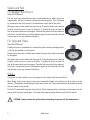
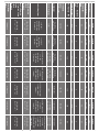
owners manual
ENGLISH
Contents
Introduction 2
Main Features 2
Unpacking 3
Plinth Fixing 3
Spikes and Feet 4
For Wooden/Hard Floors 4
For Carpeted Floors 4
Grilles 4
Setting Up 5
2 Channel Positioning 5
AV Positioning 5
Setting up the Gold FX 6
Fixing the Gold FX to a wall 8
Connecting Speaker Cables 9
Bare Wire Connection 9
Banana Plugs 9
Wiring 9
Single Wiring 9
Bi-Wiring 10
Bi-Amping 10
The Effects of Bi-Wiring/ Bi-Amping 10
Port bungs 11
Specifications 12
Owner Information 13
monitoraudio.com
1
Introduction
Born from the incredible success of the award winning GX Range, the new Gold Series furthar fine tunes its
distinguished qualities featuring new advanced driver technologies and materials amalgamated to form a
real world, yet truly esoteric speaker range. The Gold Series focuses on sonic clairty, detail and conveying
a truly honest expression of a recorded piece. Wether it be the epic cinematic soundscapes presented in a
movie, or the souring vocal melodies carried out by your favourite musical artist, the Gold Series will place
you in the moment as if you were there.
This astounding attention to detail is not only evident the sound of the new Gold but in every component part,
manufactured from only the finest materials and machined to exacting tolerances.
Main Features
•
C-CAM® Ribbon transducer design – providing extension to a class leading 60kHz.
•
New 5.5” and 6.5” bass drivers with C-CAM® cone – larger piston area offering higher efficiency and
better dynamics.
•
New 4” dedicated mid-range driver with C-CAM® cone and under-hung voice coil for very low distortion.
•
New RST® Cone profile, for improved diaphragm rigidity and reduction in distortion.
•
Die-cast Alloy chassis design for amazing rigidity and lower reflection properties.
•
HiVe® port technology offers for smoother air-flow for a superior transient response and tighter bass.
•
Single bolt through driver systems, for increased overall bracing, rigidity and driver/baffle de-coupling.
•
Die-cast alloy terminal panel arrangement with high quality bi-wire terminals and high end spade type,
Pureflow® Silver link cables.
•
Pureflow® Silver internal cabling.
•
High quality crossovers with premium grade Polypropylene film capacitors used throughout.
•
Large radius cabinet edges provide low diffraction and smoother overall frequency response.
•
Curved cabinet profile for increased rigidity and reduced internal standing waves.
•
Hand selected premium quality wood veneer (dark walnut) or high gloss piano finishes (black, white
or ebony).
•
Rigid 20mm MDF construction throughout, employing both radial and cross-bracing techniques for high
rigidity and ensuring low cabinet colouration.
•
Invisible magnetic grille fixing offers clean visual styling when used without the grille.
•
Full 3-way design (Gold 200, 300 & Gold C350).
•
Die-cast alloy plinth structures and adjustable feet with provision for both hard and carpet floors (Gold
200 and 300 only).
2
Gold Series
ENGLISH
Unpacking
Ensure there is plenty of clean floor area around where you are proposing to unpack the loudspeakers.
Remove any lose components from the packaging (feet, bolts, plinths, grilles etc) and invert the carton. Lift
the carton up and remove the packaging end cap. Remove the tape from the bag(s)revealing the bottom of
the cabinet(s).
With the Gold 50 and Gold 100, stand the cabinets upright and remove the remaining packaging end cap and
bag(s). Place the cabinets on the stands and position them according to instructions on page 5.
With the Gold 200 and Gold 300, fit the plinths and feet before proceeding any further.
Plinth Fixing
(Gold 200 & 300 only)
Fit the plinths and spiked feet to the base of each speaker. Refer to page 4.
The plinths are provided for stability as well as improving the acoustic performance of the speakers. Due
to the tapered shape of the cabinets, it is not recommended to install them without the plinths fitted as the
speakers are likely to be unstable.
Plinth Bolt
Spike
Foot
Plinth
Lock Nut
Washer
Locking nut
monitoraudio.com
3
Spikes and Feet
For Wooden/Hard Floors
(Gold 200 & 300 only)
The foot comes pre-assembled for use on hard/solid floors or where spikes are
inappropriate. All that is required is fixing them into the plinths. This is achieved
by screwing the feet fully into the 2 threaded holes in each half of the plinth.
With great care turn the cabinet the right way up. Place the cabinet in the desired
location, checking that it is level on all sides. If slightly off-level, unscrew the
foot at the lowest point and check again. Continue this process until the cabinet is
fully level. Use the locking nuts (illustrated on page 3) on each foot to fix the feet
in place and to stop any unwanted vibrations.
For Carpeted Floors
(Gold 200 & 300 only)
If being installed on carpeted floors, remove the spike from the packaging and fix
it into the foot assembly, as illustrated.
Please ensure there are no hidden wires under the carpet that could be damaged
by the spikes.
With great care turn the cabinet the right way up. Place the cabinet in the desired
location, checking that it is level on all sides. If slightly off-level, unscrew the
foot at the lowest point and check again. Continue this process until the cabinet is
fully level. Use the locking nuts (illustrated on page 3) on each foot to fix the feet
in place and to stop any unwanted vibrations.
Grilles
The grilles are held invisibly in place by magnets in the cabinet itself (except Gold FX).
When fitting, firstly ensure they are the correct orientation (badge at the bottom) and offer them up to the
cabinet. The magnets should them pull them into position, but it may need some fine adjustment to ensure
they are square on the cabinet.
The Gold FX comes with the grilles factory fitted. When removing them, carefully prise them away from the
cabinet with the tips of your fingers. There are three separate grilles fitted to each Gold FX cabinet.
CAUTION: Always remove the grilles before attempting to move or lift the loudspeakers.
4
Gold Series
ENGLISH
Setting Up
2 Channel Positioning
When arranging a 2 channel system, the listening position and the loudspeakers should form an equilateral
triangle. The speakers should be positioned approximately 6 - 10 feet (1.8 - 3m) apart. The ideal distance
from the rear wall varies depending on the speaker (see list below), however, they need to be a minimum of
3 feet (91cm) from the side walls.
•
Gold 50 and Gold 100 8 - 18 inches (20 - 45cm)
•
Gold 200 18 - 24 inches (45 - 60cm)
•
Gold 300 upto 36 inches (91cm)
Experimentation is strongly advised when initially setting up the speakers, as environment and personal
preference differ with every installation. If there is insufficient bass for example, try moving your speakers
closer to a wall. The opposite approach is recommended if there is excess bass. Also see the information
on page 11 refering to Port Bungs. If stereo imaging is being lost, try ‘toeing’ them in slightly. The sound
should appear to originate from the centre point between the speakers, not the actual speakers themselves.
AV Positioning
On pages 7 and 8, there are illustrations showing optimal positioning and some example room layouts for
AV applications.
The front, and in some cases rear, floor standing and stand mount speakers should be positioned approx 6 - 9
feet apart (1.8m - 2.5m) and start with them about 10 inches (25cm) from the wall.
If the sound is too bass heavy or there is bass boom from the room when playing music (without a subwoofer),
try moving the loudspeakers slightly further away from the wall(s) or adjusting the crossover frequency
settings for the speakers and/ or sub. Also try changing the subwoofer’s position. If this is not possible, then
try the supplied port bungs (not included in the Gold FX or Centre). Refer to Page 11.
The Gold Centre channel should be positioned so they are pointing at the viewing position and at approximate
ear height. If it is below or above ear height, use some rubber feet (small feet supplied) to angle it slightly.
The Gold FX’s should be positioned in accordance with the below illustrations and instructions, and approx 2
feet (60cm) to the bottom of the speaker above ear height when in your listening position.
NOTE: When using 2 pairs of Gold FX in a 7.1 system, set the rear surround left speaker to ‘Right’
and the rear surround right to ‘Left’. This is required due to tweeter phasing. All four speakers need
to be set to di-pole mode.
monitoraudio.com
5
Setting up the Gold FX
The Gold FX’s are independent speakers that can be tailored to be either left or right handed at the flick of
a switch. Likewise, they can be operated in either di-pole or mono-pole modes. The default factory setting
is mono-pole.
In mono-pole mode, only the main driver and tweeter will be active. In di-pole mode, the main tweeter is
disengaged and the side drivers and tweeters are active. The front firing tweeters are out of phase with the
other tweeter and mid/bass unit. It is recommended to implement this configuration when using two pairs
Gold FX as part of a 7.1 channel system, with the Gold FX’s taking up positions on side and rear walls. Please
note, it is essential they are positioned correctly when used in a 7.1 channel system. Please refer to the
switch positioning images on pages 7 and 8.
NOTE: Before adjusting any switches, please ensure that the amplifier is at the very least
turned off. This will help to protect the amplifier.
Tweeter Attenuation Switch: This switch adjusts the level of the main high
frequency tweeter unit. In the middle position, there is no attenuation. Placed
in the ‘-’ position, the high frequencies will be attenuated by 3dB. Placed in the
‘+’ position, the high frequencies will be boosted by 3dB.
Location Switch: This switch is used when determining the location of the Gold
FX’s. Please refer to the illustrations on pages 7 & 8 for correct positioning.
This will only make a difference when in ‘di-pole’ mode.
Mono-pole/ Di-pole Switch: This switch determines the actual mode of
the Gold FX. When part of 5.1 systems as a rear speaker, set the switch to
mono-pole. Although there is nothing wrong with experimenting and trying
the switch in the di-pole mode. If part of a 7.1 system as side speakers, set the
switch to di-pole. If using 4 Gold FX’s (side and rear) set them all to di-pole
mode. Please see the illustrations on pages 7 & 8 to determine the setting of
the ‘Location Switch’ depending on system set up.
If you are using the 12v trigger, set the switch to monopole mode. The trigger
will switch a relay to enable the di-pole mode.
12 volt Trigger: (Not shown) This feature is present on some AV amplifiers. It
is possible to customise the 12v trigger to switch the speakers to di-pole for
certain sources. For example, multi-channel music should be listened to in
mono-pole mode, however, movies should be listened to in di-pole mode. This
feature automates the switching between the two modes. Please refer to your
AV amplifier manual for further instruction.
6
Gold Series
ENGLISH
44 - 6
0°
135
-15
0°
5.1 system with surround
speakers on the rear wall. Floor
standing/ stand mounting speakers can
also be used.
0°
90
-1
10
°
44 - 6
5.1 system with
surround speakers
on the side wall. Floor
standing/ stand mounting
speakers can also be used.
monitoraudio.com
7
0°
90
-1
10
°
44 - 6
135
-15
0°
7.1 system with Gold FX’s
for surround and rear surround.
Floor standing/ stand mounting
speakers can also be used.
Fixing the Gold FX to a wall
CAUTION: Always determine where the Gold FX will be fixed and the structure of the wall. For
safety reasons, if unsure of your ability to provide a secure and safe fixing, do not attempt to fix
these speakers to a wall. Instead, please obtain the services of a competent and qualified trades
person.
CAUTION: Ensure that water pipes or electricity cables do not run behind where the wall plate is
going to be secured. Work from secure steps and avoid trailing wires.
NOTE: We do not supply wall fixing screws and plugs with the Gold FX. Please only use suitable
fixings for the type of wall construction the Gold FX’s will be fixed to.
To fix the Gold FX’s to a wall, we would recommend using the wall fixing template provided within the
packaging carton. Fix the wall plate to the wall, connect the speaker cables, and 12v trigger cables (if being
used) and hang the cabinet on the wall plate.
8
Gold Series
ENGLISH
Connecting Speaker Cables
Bare Wire Connection
Unscrew the binding posts and pass the bare wire through the through-hole. Tighten the binding post to
clamp the wire in place.
Banana Plugs
Remove the red and black plastic plugs from the terminals and insert the banana plugs into the standard
4mm holes that are revealed. Pliers may be required to gain purchase on the plugs.
Wiring
Single Wiring
Single wiring is acheived via a single set of cables to the terminals on the back of the loudspeaker. Internally
the loudspeaker crossover guides the frequencies to the appropriate driver/tweeter. Low frequencies to the
bass drivers, mid frequencies to the mid/bass drivers and high frequencies to the tweeter.
It is perfectly acceptable to connect to the top, bottom terminals or even diagonally (experimentation is
advisable to achieve the preferred results).
NOTE: When using this method you must keep the terminal links in place.
AMP
RIGHT
+
+
-
LEFT
monitoraudio.com
9
Bi-Wiring
Bi-wiring is accomplished by connecting separate pairs of speaker cables to the terminals on the loudspeaker
from a single pair of connections on the amplifier. In the case of the Gold Series, the bottom terminals
connect to the bass driver(s) and the top terminals connect to the tweeter in 2 way loudspeakers, or the mid
and tweeter in 2.5 and 3 way loudspeakers.
NOTE: When using this method the terminal links MUST be removed.
AMP
+
+
-
LEFT
RIGHT
Bi-Amping
Bi-Amping is the same as Bi-Wiring except you are introducing a second amplifier into the equation.
In order to Bi-Amp you must connect a set of speaker cables to the top terminals on the loudspeaker from
one amplifier and another set of speaker cables to the bottom terminals from the second amplifier.
NOTE: When wiring this method the terminal links MUST be removed.
AMP
+
+
-
LEFT
RIGHT
AMP
+
+
-
-
RIGHT
LEFT
The Effects of Bi-Wiring/ Bi-Amping
Fundamentally a loudspeaker crossover varies the impedance seen by the speaker and by the power
amplifier. The situation is such that when the full range musical signal is applied to the terminals of a fullrange speaker system, the bass driver(s) only receives low frequency signals, the mid driver receives the mid
band frequency signals and the tweeter only gets sent high frequency signals. This means that if separate
speaker cables are connected to the low frequency terminals, and the high frequency terminals, not only
have the drive units and the frequency’s directed and divided for them, but the two separate speaker cables
will now also carry different signals, the bass cable mostly the lows, and the tweeter cable mostly the highs.
Once the high and low frequencies have been separated in this fashion, the strong current pulses and surges
demanded by bass drivers when reproducing bass or drums, will not interact with the delicate sounds of a
flute or cymbal.
10
Gold Series
In terms of the audible benefit, bi-wiring/ bi-amping, provides more clarity and detail to the midrange and
high frequencies. Often the bass will become faster and tighter. Focus and staging will improve as well. In
all, this is a very effective and desirable improvement and is highly recommended by Monitor Audio.
Port bungs
WARNING: Care must be taken not to insert the port bungs too far into the port, as this may result
in the foam bung being lost inside the cabinet.
If the loudspeaker is to be installed in a small room, typically 9 sqM (80 sqFT), or a room known to reproduce
accentuated bass response, it may be desirable to fit port bungs. However, experimentation is recommended
with positioning of the loudspeaker in the room prior to fitting. To optimise performance from the loudspeaker
it is important to ensure the loudspeaker is not positioned too close to a wall or near the corners of a room
(refer to the suggestions on page 5).
If the positioning of the loudspeaker is predetermined by room aesthetics or layout, or you find you have
accentuated bass, please move on and read point 1 for the Gold 50/ Gold 100 and point 2 for the Gold 200/
Gold 300.
1. Where stand-mount speakers (Gold 50 & Gold 100) are to be sited in close proximity (less than 8
inches/ 20cm) to a rear wall (such as on a bookshelf, positioned in a cabinet or on a stand close to
a wall), we recommend fitting port bungs to the ports. This will reduce the bass ‘boom’ sometimes
termed as overhang, and assist the loudspeakers to reproduce their best performance under these
environmental conditions. ‘Boom’ is generally caused when bass energy from the loudspeaker ‘excites’
room modes and causes an accentuation at a particular frequency, or number of frequencies.
2. Where floor-standing loudspeakers (Gold 200 & Gold 300) are to be sited in close proximity (closer than
18 inches/ 45cm) to a rear wall, we recommend fitting the port bungs. This will reduce the bass ‘boom’
sometimes termed as overhang and assist the loudspeakers to reproduce their best performance under
these environmental conditions. This is caused when bass energy from the loudspeaker ‘excites’ room
modes and causes an accentuation at a particular frequency, or number of frequencies.
When fitting port bungs the overall bass extension will not be reduced, however bass energy/ output
around the port tuning frequency will be reduced. This has the effect of reducing bass ‘boom’ while
increasing bass clarity and apparent agility.
In all circumstances experimentation is highly recommended.
monitoraudio.com
11
ENGLISH
In a single wired system, unwanted mechanical and electrical resonances manifest as distortion at both
sets of speaker terminals. Due to the impedance of the speaker cables, these distortions will not be entirely
cancelled by the amplifier. Instead, they modulate between the two crossovers, and degrade sound quality.
When bi-wiring, this interaction is minimised as signal distortion is ‘seen’ at the amplifier’s output where it
can be more effectively cancelled. Bi-wiring/ bi-amping therefore presents a ‘cleaner’ signal at both the low
frequency and high frequency speaker terminals, and because the high and low frequencies have already
been separated, each has a minimal effect on the other - in essence the bass does not overpower delicate
treble.
System Format
60Hz – 60kHz
2 Way
40Hz – 60kHz
87
Gold FX
55Hz – 60kHz
90
8
3 Way
30Hz – 60kHz
89
8
110.8
Gold C350
35Hz – 60kHz
90
8
113.8
100
2 Way
42Hz – 60kHz
89
8
111.5
200
50 - 100
Gold C150
55Hz – 60kHz
88
8
116.8
150
100 - 200
Sealed Cabinet
3 Way
86
8
114.5
200
100 - 150
Sealed Cabinet
Bi-Pole: 2.3kHz
Di-pole: 2.6kHz
Gold 300
8
112.6
150
100 - 200
Sealed Cabinet
L.F - M.F: 800Hz
M.F - H.F: 2.3kHz
1 x 6.5” RST® bass driver
2 x 4” C-CAM®
mid-range driver
1 x C-CAM® ribbon
H.F transducer
2 x 25mm Gold C-CAM®
dome tweeter
3 Way
109.8
120
100 - 150
HiVe® port system
2.8kHz
2 x 6.5” RST® bass driver
1 x 4” RST®
mid-range driver
1 x C-CAM® ribbon H.F
transducer
310 x 390 x 160
12 3/16 x 15 3/8 x 6 5/16
Gold 200
Maximum SPL (dBA)
100
60 - 120
Bass Reflex.
HiVe® port system
L.F - M.F: 790Hz
M.F - H.F: 2.3kHz
2 x 5.5” RST® bass driver
1 x C-CAM® ribbon H.F
transducer
254 x 581 x 333
10 x 22 7/8 x 13 1/8
310 x 390 x 168
12 3/16 x 15 3/8 x 6 5/8
2 Way
Power Handling - RMS
(W)
50 - 100
Bass Reflex.
HiVe® port system
L.F - M.F: 400Hz
M.F - H.F: 2.6kHz
2 x 6.5” RST® bass driver
1 x 4” RST®
mid-range driver
1 x C-CAM® ribbon H.F
transducer
172 x 461 x 303
6 11/16 x 18 1/8 x 11 15/16
254 x 581 x 360
10 x 22 7/8 x 14 3/16
11.9 (26lb 2oz)
Gold 100
Recommended
Amplifier
Requirements (W)
Bass Reflex.
HiVe® port system
2.7kHz
2 x 5.5” RST® bass driver
1 x 4” RST®
mid-range driver
1 x C-CAM® ribbon
H.F transducer
1060 x 210 x 330
41 3/4 x 8 1/4 x 13
172 x 461 x 330
6 11/16 x 18 1/8 x 13
9.9 (21lb 12oz)
2 Way
Bass Alignment
2.3kHz
1 x 6.5” RST®
bass / mid driver
1 x C-CAM® ribbon H.F
transducer
951 x 170 x 300
37 7/16 x 6 11/16 x 11 13/16
1105 x 317 x 370
43 1/2 x 12 1/2 x 14 9/16
6 (13lb 4 oz)
Gold 50
Crossover Frequency
1 x 5.5” RST®
bass / mid driver
1 x C-CAM® ribbon
H.F transducer
362 x 210 x 303
14 3/8 x 8 1/4 x 11 15/16
995 x 274 x 370
39 3/16 x 10 13/16 x 14 9/16
27.2 (59lb 14oz)
Frequency Response
Drive Unit Compliment
300 x 170 x 263
11 13/16 x 6 11/16 x 10 3/8
362 x 210 x 330
14 3/8 x 8 1/4 x 13
22.2 (48lb 14oz)
Nominal
(ohms)
Impedance
Sensitivity (dB)
1W@1m
Cabinet Dimensions
HxWxD
mm (inches)
300 x 170 x 290
11 13/16 x 6 11/16 x 11 7/16
9.9 (21lb 12 oz)
Specifications
Bass Reflex.
Complete Dimensions
Inc Terminals, Plinths
& Spikes
HxWxD
mm (inches)
7.5 (16lb 8oz)
Product Weight
kg (Ibs)
ENGLISH
Owner Information
Product Details
Model Product Serial No Date of Purchase Dealer Details
Dealer Name Address e-mail address Telephone Number Monitor Audio reserves the right to alter specifications without notice.
For the 5 years manufacturer’s warranty, please visit the online registration form at:
www.monitoraudio.com
monitoraudio.com
13