1
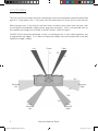
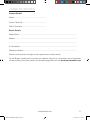
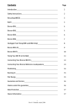
MONITOR REFERENCE
o w n e r s
m a n u a l
m o n i t o r a u d i o . c o . u k
Monitor Ref Manual Rev1.2.indd 1
30/03/2012 10:37:39
Monitor Ref Manual Rev1.2.indd 2
30/03/2012 10:37:39
Contents Page
Introduction 1
Positioning 2
AV Positioning 2
2 Channel Positioning 3
Spike Fixing 3
Wiring Configurations 4
Port Bungs 5
Amp Panel & Controls 6
Positioning & Initial set Up of MRW-10 8
Set Up 9
Trouble Shooting 9
Specifications 10
Owner Information 11
introduction
Thank you for purchasing the Monitor Reference Series loudspeakers.
By using the finest materials around, we have been able to use our decades of expertise in
developing quality loudspeakers to bring the Monitor Reference series to life.
Resplendent in a stunning black oak vinyl furniture finish and built with the accuracy that
exemplifies the Monitor Audio brand world-wide, the six model strong Monitor Reference Series
will look gorgeous in any room.
monitoraudio.com
Monitor Ref Manual Rev1.2.indd 1
1
30/03/2012 10:37:39
positioning
AV Positioning
The front, and in some cases rear, floor standing and stand mount speakers should be positioned
approx 6 - 9 feet apart (1.8m - 2.5m) and start with them about 10 inches (25cm) from the wall.
When playing music, if the sound is too bass heavy or there is bass boom from the room, then
try moving the loudspeakers slightly further away from the wall(s). If this is not possible, then try
the supplied port bungs (not included in the MR Centre). Refer to Page 5.
The MR Centre should be positioned so that it is pointing at you, in your viewing position, and
at approximate ear height. If it is below or above ear height, use some rubber feet (small feet
supplied) to angle it slightly.
Left
Centre
0°
Right
22°
30°
90°
Surround
Left
Surround
Right
110°
135°
150°
Rear
Surround
Left
2
Monitor Ref Manual Rev1.2.indd 2
Rear
Surround
Right
Monitor Reference Series
30/03/2012 10:37:39
2 Channel Positioning
For use in a 2 channel system, the listening position and the loudspeakers should form an
equilateral triangle. The speakers should be positioned approximately 6 - 10 feet (1.8 - 3m)
apart. They ideally need to be between 8 - 18 inches (20 - 45cm) away from the rear and 3 feet
(1m) from the side walls.
Experimentation is strongly advised when initially setting up your speakers, as environments and
personal preference differ with each installation. If there is not enough bass, for example, then
try moving your speakers closer to a wall. The opposite, if there is too much bass. Also see the
information on page 5 refering to Port Bungs. If you are loosing stereo imaging, try ‘toeing’ them
in slightly. The sound should appear to originate from the centre point between the speakers,
not the actual speakers themselves.
Spike Fixing
The Monitor Reference Series floor standing loudspeakers, come with spikes. These enhance
the acoustic performance of the loudspeaker and should be used where possible. The spikes
can be found in the packaging of the MR4 and MR6 only.
BEWARE. The spikes are very sharp, and could cause injury if care is not taken when
handling them.
Please ensure there are no hidden wires under the carpet, or trailing mains leads that
could be damaged by the spikes.
1. Carefully place the cabinet on it’s top or back to fit the spikes.
2. Screw the spikes into the threaded inserts on the bottom of the cabinets.
3. Carefully turn your speaker back over and check that it is evenly balanced. If uneven, you
can adjust the height in the appropriate (lowest) corner by unscrewing the spike slightly. This
operation may need to be repeated a several times to ensure your cabinet is completely
level. When you are happy with the balance of the cabinet, tighten the locking nut on each
spike.
monitoraudio.com
Monitor Ref Manual Rev1.2.indd 3
3
30/03/2012 10:37:39
Wiring configurations
Single Wire
For the MR1 and MR Centre, there are
only one pair of terminals (as in illustration
opposite). This means it is only possible
to single wire these speakers.
Single Wire
The MR2, MR4 & MR6 all have two pairs
of terminals. By running one pair of cables
(one positive and one negative) you will be
single wiring them.
When single wiring these speakers, you
must leave the terminal links in.
Bi-Wire or
Bi Amp
By running two pairs of cables (two
positive and two negative) from a single
pair of terminals on your amp, you will be
bi-wiring them.
Some AV amplifiers support bi-amping.
This is very similar in process to bi-wiring,
except the two pairs of cables will not
be joined at the amplifier end to a single
set of terminals, they go to two pairs of
terminals. Bi-amping is also achieved by
using two stereo amplifier.
By bi-wiring/ bi-amping them you will get
a cleaner, more smooth sound with tighter
mid and more controlled bass.
When bi-wiring these speakers, you must
remove the terminal links. Failure to do so
will result in damage to your amp.
4
Monitor Ref Manual Rev1.2.indd 4
Monitor Reference Series
30/03/2012 10:37:41
Port bungs
WARNING: Care must be taken not to insert the port bungs too far into the port, as
this may result in the foam bung being lost inside the cabinet.
If the loudspeaker is to be installed in a small room, typically 9 sqM ( 80 sqFT), or a room
known to reproduce accentuated bass response, it may be desirable to fit port bungs. However,
experimentation is recommended with positioning of the loudspeaker in the room prior to fitting.
To optimise performance from the loudspeaker it is important to ensure the loudspeaker is not
positioned too close to a wall or near the corners of a room (refer to the suggestions on pages
2 and 3).
If the positioning of the loudspeaker is predetermined by room aesthetics or layout, or you find
you have accentuated bass, please read point 1 for the MR1 & MR2 and point 2 for the MR4 &
MR6.
1. Where bookshelf/ stand-mount speakers (MR1 & MR2) are to be sited in close proximity
(less than 8 inches/ 20cm) to a rear wall (such as on a bookshelf, wall mounted, positioned
in a cabinet or on a stand close to a wall), we recommend experimenting with fitting port
bungs into the ports. This will reduce the bass ‘boom’ sometimes termed as “overhang”,
and assist the loudspeakers to reproduce their best performance under these environmental
conditions. ‘Boom’ is generally caused when bass energy from the loudspeaker ‘excites’
room modes and causes an accentuation at a particular frequency, or number of frequencies.
2. Where floor-standing loudspeakers (MR4 & MR6) are to be sited in close proximity (closer
than 18 inches/ 45cm) to a rear wall, we recommend experimenting fitting the port bungs.
This will reduce the bass ‘boom’ sometimes termed as overhang and assist the loudspeakers
to reproduce their best performance under these environmental conditions. This is caused
when bass energy from the loudspeaker ‘excites’ room modes and causes an accentuation
at a particular frequency, or number of frequencies.
When fitting port bungs the overall bass extension will not be reduced, however bass energy/
output around the port tuning frequency will be reduced. This has the effect of reducing bass
‘boom’ while increasing bass clarity and apparent agility.
Experimentation is highly recommended.
monitoraudio.com
Monitor Ref Manual Rev1.2.indd 5
5
30/03/2012 10:37:41
Amp Panel & Controls for MRW-10
Title : MONITOR MRW-10 AMP PANEL ARTWORK
Date: 2ND MARCH 2011
PAINTED
TEXT : WHITE
FONT : HELVETICA & ARIAL
1
2
5
3
6
4
7
TO RE
COV
RE
AFIN DE RÉD
LE COUVERCLE
PAR L’UTILIS
8
9
10
11
10a
Notes:
1. ARTWORK SCREENPRINTED ON.
2. COLOUR : WHITE
6
Monitor Ref Manual Rev1.2.indd 6
Monitor Reference Series
30/03/2012 10:37:41
1. Power Mode Switch with On-Auto-Off Facility
The Power Mode Switch has three positions: ‘On’–‘Auto’–‘Off’. With the switch in the ‘On’
position, the subwoofer is permanently switched on under all conditions. In the ‘Auto’
position the subwoofer will automatically switch on when an input signal is received and will
remain on until no signal is received for around 10-15 minutes, the MRW-10 will then switch
into standby mode until a signal is received once more. When the switch is in the ‘Off’
position the subwoofer will not function.
2. Phase
The phase control is used to synchronise the output between the MRW-10 and main/
satellite speakers. For most applications this should be set to 0 degrees.
3. By Pass Filter Switch
When set to the ‘Off’ position the crossover frequency control (section 4) is activated and
can be adjusted from 45Hz to 150Hz using the crossover frequency control. In this position
it can be used with an amplifier that does not have a dedicated subwoofer or LFE output,
such as a stereo 2-channel amplifier. If the amplifier or AV processor has a dedicated LFE
or subwoofer output, the By Pass Filter Switch should be set to the ‘On’ position. The low
pass filter will then be set by the AV amplifier’s internal filter. This is set in accordance with
the amplifier or AV processor user guide. The table below can be used to set the frequency.
4. Crossover
This feature controls the upper frequency limit of the MRW-10, and will only be active when
the switch (above) is in the ‘Off’ position. The table below will help you to select the correct
frequency at which to crossover depending on your main speakers.
Type of Main Speaker
Monitor Reference
Series Product
Crossover Control Setting
Small stand-mount/
bookshelf speaker
MR1/ MR2
60-100 Hz
Floor Standing Speaker
MR4/ MR6
40 - 80 Hz
5. Power LED
The LED indicates whether the unit is in stand-by mode or operational. It will be illuminated
red when in stand-by, and green when operational.
6. Volume
This control allows the subwoofer level or loudness to be adjusted in order that you can
achieve a totally controlled, balanced sound.
7. RCA Phono Input Connection
This is the only method of signal input connection to the MRW-10. When using a stereo
amplifier system, connection can be provided by a pair of high-quality signal cables from the
pre-out section of an amplifier. If a digital AV processor or AV receiver/amplifier is to be used,
a single cable can be connected from the ‘sub out’ or LFE connection on the amplifier to the
RCA input connection on the MRW-10 labelled ‘R’. The RCA input marked ‘L’ in this case
will remain unused. Note: - cable lengths should not exceed 10 metres to avoid interference
from other electrical appliances.
8. Warning Information
See warning information in separate safety instructions booklet
monitoraudio.com
Monitor Ref Manual Rev1.2.indd 7
7
30/03/2012 10:37:42
9. Power Switch
The Mains Power Switch should be switched to the ‘Off’ position when the MRW-10 will not
be used for extended periods. The switch must be in the ‘On’ position for the subwoofer
to function.
WARNING: Due to the mains switch being located on the rear panel, the apparatus must be
located in the open area with no obstructions to access the mains switch.
10.IEC Mains Power Connector/ Fuse Location
The MRW-10 is supplied with a two-pin mains input socket for connection to the mains
supply. Use ONLY the appropriate IEC mains lead provided with the product. Also fitted is
an external mains fuse. If this fuse blows during operation a spare fuse is provided within
the fuse holder for replacement. If you wish to change the fuse, you can do this by removing
the IEC mains lead and carefully levering out the original fuse from its holder below the
IEC mains input socket (10a). If the fuse blows again it is advisable to seek help from an
authorised service agent. DO NOT attempt to re-fit a further fuse as this could result in
serious damage to the amplifier unit.
11.Mains Voltage Selector
This is factory set to your country’s mains voltage specification. Do not attempt to adjust this
as this may lead to permanent damage to the product and even the risk of fire. There is a
clear plastic cover over the selector to prevent accidental adjustment.
Positioning / Initial Set Up of MRW-10
Leave the subwoofer unplugged from the mains until the installation procedure is
completed. The subwoofer should now be sited in the most suitable position. If placed in a
corner of the room there may be excessive bass ‘boom’. Once a desirable position is achieved
it is important to check if the cables are long enough to reach comfortably without being under
tension. The optimal control settings will depend entirely on your system configuration. For initial
trials set the controls as follows:
Volume Control
Should be set to minimum
Frequency Control
Should be set to the 12 o’clock position
Phase Control
Should be set to zero degrees
Power Mode Switch
Should be set to ‘On’
By Pass Filter Switch
Should be set to the ‘On’ for AV and ‘Off’ for 2 channel listening.
Input connections can be made at this stage before the power is connected to the subwoofer.
Never connect or disconnect any leads with the subwoofer connected to
the mains.
8
Monitor Ref Manual Rev1.2.indd 8
Monitor Reference Series
30/03/2012 10:37:42
Set Up
Once the input cables are connected and the controls are set in accordance with the initial set-up
procedure above, the subwoofer can be connected to the mains power supply and switched on
at the mains power switch.
•
For use with an AV amp/ receiver (product with sub woofer output) run the auto set up on the
AV amp. Check the settings it has supplied and carry out fine adjustment if necessary. This
may include adjusting the gain or crossover frequency on the AV amp or level on the sub
woofer. The crossover frequency should be similar to that in the table on page 7.
Play some familiar movies to double check it integrates with the system and carry out any
adjustments to the levels or crossover frequency if necessary.
•
For use with a stereo amp (product without Sub woofer output), set the crossover frequency
control in accordance with the table on page 7. The level may need to be adjusted so that
it integrates at all levels. Further fine-tuning of the crossover frequency may be required.
•
The Phase Control can now be set, please refer to page 10 for further information. It is
important to try a variety of music and film excerpts with which you are familiar in order to
obtain the optimum overall settings.
Trouble Shooting
Should you experience any technical, or set-up problems with your subwoofer please check the
Trouble Shooting Guide below:
My subwoofer will not turn on/ no power.
•
Is the LED illuminated on the unit? If not, then check your mains lead is properly connected
both at the subwoofer and at the mains outlet. Also check the fuse of the mains plug (where
fitted) and also the fuse in the subwoofer. See page 8 for further information on changing
the fuse and it’s location.
•
Is the LED red? If so, you have power going to the unit. It could be that there is no signal.
•
Is there a signal going to the subwoofer? If there is a signal present, is the Power Mode
Switch in the Auto or On position, and the source is turned on? Try adjusting the volume
level of the source and try the switch in the ‘On’ position.
If it still does not turn on/ power up, please contact your local dealer/ distributor or Monitor Audio
immediately.
No sound from subwoofer.
•
Is the LED red or green? If it is red, then the unit hasn’t actually turned on, see suggestions
above. If it is green, then your unit is powered up and turned on. Check further suggestions
below.
•
Are the signal leads connected correctly? Check these. If possible, check with a second,
known to be working set.
•
Is the volume level just very low?
If it still does not output a signal, please contact your local dealer/ distributor or Monitor Audio
immediately.
monitoraudio.com
Monitor Ref Manual Rev1.2.indd 9
9
30/03/2012 10:37:42
MRW-10
Drive unit
Complement
Bass Alignment
Recommended Amp
Requirements
Power Handling (RMS)
Nominal
Impedance
Sensitivity
(1w @ 1m)
Frequency Response
Model
260 x 165 x 180
1 x 5.5” MMP®II
Bass/ Mid driver.
1 x 1” (25mm)
C-CAM® gold dome
tweeter
Bass Reflex –
Rear Ported.
15 - 70W
70W
6 Ohms
88dB
55Hz - 30kHz
MR1
350 x 185 x 250
1 x 6.5” MMP®II
Bass/ Mid driver.
1 x 1” (25mm)
C-CAM® gold dome
tweeter
Bass Reflex –
Front Ported.
30 - 100W
100W
6 Ohms
90dB
42Hz - 30kHz
MR2
850 x 185 x 255
1 x 6.5” MMP®II
Bass driver.
1 x 6.5” MMP®II
Bass/ Mid driver.
1 x 1” (25mm) C-CAM®
gold dome tweeter
Bass Reflex Front and
Rear Ported.
30 - 120W
150W
6 Ohms
91dB
36Hz - 30kHz
MR4
970 x 200 x 300
2 x 6.5” MMP®II
Bass driver.
1 x 6.5” MMP®II
Bass/ Mid driver.
1 x 1” (25mm) C-CAM®
gold dome tweeter
Bass Reflex Front and
Rear Ported.
40 - 150W
150W
6 Ohms
90dB
33Hz - 30kHz
MR6
6 1/2 x 18 1/8 x 6 1/2
165 x 460 x 165
2 x 5.5” MMP®II
Bass/ Mid driver.
1 x 1” (25mm)
C-CAM® gold dome
tweeter
Sealed Cabinet
20 - 120W
120W
6 Ohms
91dB
60Hz - 30kHz
MR Centre
specifications
External Dimension
H x W x D (mm)
38 3/16 x 7 7/8 x
11 13/16
Weight
Kg (lbs)
33 7/16 x 7 5/16 x 10 1/16
External
Dimmensions
(H x W x D)
mm (Inches)
12.9
(28.4)
13 3/4 x 7 5/16 x
9 13/16
Mains Input
Voltage
(Factory Preset)
320 x 280 x 280
12 5/8 x 11 x 11
10 1/4 x 6 1/2 x
7 1/16
Input
Impedance
110 - 120Vac
220 - 240Vac
External Dimensions
H x W x D (inch)
Driver
Complement
20K Ohms
6.2 (13.6)
Cabinet
Alignment
1 x 10”Long
Through Driver
17.2 (37.8)
Low Pass
Filter
Alignment
Bass Reflex,
18mm
construction
12 (26.4)
Amplifier
Output
12dB/ octave
filter
5.6 (12.3)
Upper
Frequency
Limit
(Variable)
100W
3.5 (7.7)
Low
Frequency
Limit
45 - 150Hz
Weight (each)
Kg (lb)
28Hz
30/03/2012 10:37:42
Monitor Ref Manual Rev1.2.indd 10
Monitor Reference Series
10
Owner Information
Product Details
Model .................................................................
Product Serial No ................................................
Date of Purchase ................................................
Dealer Details
Dealer Name .....................................................................................................................
Address .............................................................................................................................
...........................................................................................................................................
E-mail address ...................................................................................................................
Telephone Number ............................................................................................................
Monitor Audio reserves the right to alter specifications without notice.
For the 5 years manufacturer’s warranty for speakers, 2 years for sub woofers and to be entered
into our monthly prize draw, please visit the online registration form at: www.monitoraudio.com
monitoraudio.com
Monitor Ref Manual Rev1.2.indd 11
11
30/03/2012 10:37:42
Monitor Ref Manual Rev1.2.indd 12
30/03/2012 10:37:42
Monitor Ref Manual Rev1.2.indd 13
30/03/2012 10:37:42
m o n i t o r a u d i o . c o . u k
Monitor Audio Ltd.
24 Brook Road
Rayleigh, Essex
SS6 7XJ
England
Tel: +44 (0)1268 740580
Fax: +44 (0)1268 740589
Email: [email protected]
Web: www.monitoraudio.com
Designed in the United Kingdom
© 2011. Version 1
Monitor Ref Manual Rev1.2.indd 14
30/03/2012 10:37:42