1
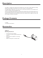
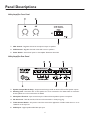
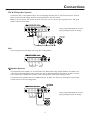
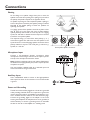
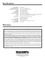
Utility Amplifier
GA6A Model
Installation and Use Manual
© 2004 Bogen Communications, Inc.
All rights reserved.
Specifications subject to change without notice.
54-5757-03B 0406
Notice
IMPORTANT
Every effort was made to ensure that the information in this
manual was complete and accurate at the time of printing.
However, information is subject to change.
Important Safety Information
WARNING: To Reduce The Risk of Fire Or Electric Shock,
Do Not Expose This Apparatus To Rain Or Moisture.
Always follow these basic safety precautions when installing and
using the unit:
1.
2.
3.
4.
5.
6.
7.
8.
9.
10.
11.
12.
13.
Read these instructions.
Keep these instructions.
Heed all warnings.
Follow all instructions.
Do not use this apparatus near water.
Clean only with dry cloth.
DO NOT block any ventilation openings. Install in accordance with the manufacturer’s instructions.
Do not install near any heat sources such as radiators, heat
registers, stoves, or other apparatus (including amplifiers)
that produce heat.
Do not defeat the safety purpose of the polarized or
grounding-type plug. A polarized plug has two blades with
one wider than the other. A grounding-type plug has two
blades and a third grounding prong. The wide blade, or the
third prong, are provided for your safety. If the provided plug
does not fit into your outlet, consult an electrician for
replacement of the obsolete outlet.
Protect the power cord from being walked on or pinched,
particularly at plugs, convenience receptacles, and the point
where they exit from the apparatus.
Only use attachments/accessories specified by the manufacturer.
Unplug this apparatus during lightning storms or when
unused for long periods of time.
Refer all servicing to qualified service personnel. Servicing is
required when the apparatus has been damaged in any way,
such as power supply cord or plug is damaged, liquid has
been spilled or objects have fallen into the apparatus, the
apparatus has been exposed to rain or moisture, does not
operate normally, or has been dropped.
CAUTION: TO PREVENT THE RISK OF ELECTRIC SHOCK, DO NOT REMOVE COVER (OR
BACK). NO USER-SERVICEABLE PARTS
INSIDE. REFER SERVICING TO QUALIFIED
PERSONNEL.
The lightning flash with arrowhead symbol, within an equilateral triangle, is
intended to alert the user to the presence of uninsulated “dangerous voltage”
within the product’s enclosure that may
be of sufficient magnitude to constitute
a risk of electric shock to persons.
The exclamation point within an equilateral triangle is intended to alert the
user to the presence of important
operating and maintenance (servicing)
instructions in the literature accompanying the appliance.
Description
The GA6A is a rugged six-watt, dual-input audio amplifier with a wide variety of smaller applications including
background music, relaying communication from one room to another, or sound reinforcement.
The GA6A delivers rated power at not more than 1% total harmonic distortion from 75-15,000 Hz into
transformer-coupled or direct low-impedance loads.
Inputs for a low-impedance balanced dynamic microphone and an auxiliary audio source (tuner, tape deck, etc.) can
be mixed. Individual front-panel controls regulate the level of each input. Connections for 8-ohm and 25V or 70V
speaker lines are provided on the rear panel output terminal strip. A 3-position switch is supplied to provide +9 dB
boost, -9 dB cut at 10 kHz or flat response.
Package Contents
(1) GA6A
(1) Installation and Use Manual
Accessories
WMT1A
Matching Transformer
•
Hi-Z, 10k-ohm primary impedance
•
Lo-Z, 600-ohm secondary impedance, balanced with
center tap
•
Matches high-to-low impedance or low-to-high
impedance
•
Adapts line level signals to microphone inputs
3
Panel Descriptions
Utility Amplifier Front Panel
1. MIC Control - Regulates the level of microphone output to speakers.
2. AUX Control - Regulates the level of the AUX source to speakers.
3. Power Switch - Controls AC power to the amplifier. Illuminates when ON.
Utility Amplifier Rear Panel
1. Speaker Output Barrier Strip - Output terminal strip provides for 8-ohm, 25V, and 70V speaker outputs.
2. Shorting Link - Used when 25V or 70V speakers are to be connected to the GA6A. Must be removed if
8-ohm speakers are to be connected to the GA6A.
3. Microphone Terminal - Input terminal strip for a balanced low-impedance dynamic microphone.
4. AC Line Cord - 120V AC, 60 Hz, 0.15A line cord terminated in a three-prong plug.
5. Treble Control Switch - A 3-position switch that controls the application of 9 dB of treble boost or cut at
10,000 Hz or flat response.
6. AUX Input - High-impedance AUX RCA jack input.
4
Connections
70V & 25V Speaker Systems
Connect the 25V or 70V speaker loads to the corresponding terminals (25V or 70V) and the common terminal.
Make sure that the total wattage of all the connected speakers is less than 6 watts.
Note: Do not use both the 25V and 70V terminals at the same time. Use only one type of speaker (25V or 70V) for all
speakers connected to the GA6A.
Note: If using multiple speakers, check for
proper phasing. See Section on Phasing.
Link
The shorting link must be in place when using 25V or 70V speakers.
Ω Speaker Systems
8Ω
Low-impedance 8-ohm speakers can be connected to the GA6A.When using multiple speakers, the installer must
make sure that the total speaker load is not less than 8 ohms. Higher impedances than 8 ohms are safe to connect
to the GA6A, but the GA6A will not deliver its full output power to these higher impedance loads.
Connect the 8-ohm speaker load to the GND and 8-ohm terminals and remove the shorting link. 25V and 70V
outputs will not work in this configuration.
Note: If using multiple speakers, check for
proper phasing. See Section on Phasing.
5
Connections
Phasing
As the voltage on a speaker changes from plus to minus, the
speaker cone moves from pushing out to pulling in. If you reverse
the polarity, the speaker responds in the opposite manner.
If a speaker is pushing out and an adjacent speaker is pulling in,
some of the pressure caused by the speaker pushing out will be
absorbed by the speaker pulling in. These two speakers are
operating out of phase.
Microphone Input
Connect a low-impedance dynamic microphone (these
microphones connect using 3 wires and do not require a power
source) to the microphone terminals as shown.
Note: Condenser microphones will not work with the GA6A because
the GA6A does not supply phantom power, which is required for these
microphones to operate.
Use two-conductor shielded cable for a balanced input and
connect the shield to the ground terminal.
Auxiliary Input
Use a shielded RCA cable to connect to the high-impedance
AUX input.The center of the connector is hot and the outside
is ground.
Power and Grounding
The AC line cord should be plugged into a three-wire, grounded
outlet providing 120V AC, 60 Hz. It is important to ground the
unit. If a three-wire outlet is not available, use an adapter to convert a standard two-wire outlet for use with three-wire plugs.
Connect the grounding pigtail on the adapter to the screw
securing the wall plate. If the wall plate screw is not grounded, it
will be necessary to connect a grounding wire from the GND
terminal on the rear of the amplifier to a suitable ground.
6
_
_
_
The important thing is to wire all the same polarity (+ or -)
connections together. This will ensure that the speakers in the
system all work in unison.All paging speaker connections have a
polarity indicator. It may be a color code, plus (+) and minus (-)
symbols, or a red dot.
_
In a paging system, all the speakers should be in phase so that
they all push out at the same time. Out of phase speakers
operate perfectly well and will not cause any harm to a paging
system, but will tend to diminish the bass response in the area
around the out of phase speaker.
+
+
+
+
Out-of-phase speaker connection.
Operation
Power
The AC line cord should be plugged into a three-wire, grounded outlet
providing 120V AC, 60 Hz. The power switch illuminates when unit is
switched ON.
MIC Control
Controls the amount of MIC signal heard at the output. Clockwise
increases the signal.
AUX Control
Controls the amount of AUX signal heard at the output. Clockwise
increases the signal.
Treble Control Switch
Provides a stepped increase or decrease in high frequency (above
10 kHz) heard at the output.The “Cut” position can help reduce high
frequency feedback. The “Flat” position provides no modification to
high frequency response. The “Boost” position provides more clairty
and intelligibility to speech.
Overload Protection
The amplifier output is protected against overload and shorted speaker
lines by a thermostat enclosed in the power transformer. If the breaker
opens, the amplifier will have no output. Set the Power switch to OFF
and wait a reasonable time for the breaker to reset. If the breaker trips
again, have the trouble investigated by a qualified technician.
7
Specifications
Power Output:
Frequency Response:
Total Harmonic Distortion:
Inputs:
Sensitivity:
Hum & Noise:
Output Impedance:
Tone:
Controls:
Terminations:
Protection:
Power Consumption:
Dimensions:
Shipping Weight:
6 watts RMS
30 Hz - 12 kHz +0 dB, -3 dB
Less than 1% at rated output power
Lo-Z MIC, balanced; AUX
MIC 0.3 mV; AUX 0.2V
MIC -50 dB; AUX -70 dB
8 ohms, 25V and 70V speakers
Treble boost at 10 kHz 9 dB, treble cut at 10 kHz 9 dB (switch selected)
MIC, AUX, illuminated POWER switch, tone switch
Outputs & microphone: screw terminals
Auxiliary: RCA phono jack
Power thermal protection
120V AC, 60 Hz, 16W
8-1/2" W x 6" D x 2-5/8" H (21.6 x 15.2 x 6.7 cm)
5 lb. (2.3 kg)
Warranty
The GA6A is warranted to be free from defects in material or workmanship for two (2) years from the date of sale to the original
purchaser. Any part of the product covered by this warranty that, with normal installation and use, becomes defective will be
repaired or replaced by Bogen, at our option, provided the product is shipped insured and prepaid to: Bogen Factory Service
Department, 50 Spring Street, Ramsey, NJ 07446, USA. The product will be returned to you freight prepaid. This warranty does
not extend to any of our products that have been subjected to abuse, misuse, improper storage, neglect, accident, improper
installation or have been modified or repaired or altered in any manner whatsoever, or where the serial number or date code has
been removed or defaced.
THE FOREGOING LIMITED WARRANTY IS BOGEN’S SOLE AND EXCLUSIVE WARRANTY AND THE PURCHASER’S SOLE
AND EXCLUSIVE REMEDY. BOGEN MAKES NO OTHER WARRANTIES OF ANY KIND, EITHER EXPRESS OR IMPLIED,
AND ALL IMPLIED WARRANTIES OF MERCHANTABILITY OR FITNESS FOR A PARTICULAR PURPOSE ARE HEREBY DISCLAIMED AND EXCLUDED TO THE MAXIMUM EXTENT ALLOWABLE BY LAW. Bogen's liability arising out of the manufacture, sale or supplying of products or their use or disposition, whether based upon warranty, contract, tort or otherwise, shall be
limited to the price of the product. In no event shall Bogen be liable for special, incidental or consequential damages (including,
but not limited to, loss of profits, loss of data or loss of use damages) arising out of the manufacture, sale or supplying of products,
even if Bogen has been advised of the possibility of such damages or losses. Some States do not allow the exclusion or limitation
of incidental or consequential damages, so the above limitation or exclusion may not apply to you. This warranty gives you
specific legal rights, and you may also have other rights which vary from State to State.
Products that are out of warranty will also be repaired by the Bogen Factory Service Department -- same address as above or call
201-934-8500. The parts and labor involved in these repairs are warranted for 90 days when repaired by the Bogen Factory
Service Department. All shipping charges in addition to parts and labor charges will be at the owner's expense. All returns require
a Return Authorization number.
50 Spring Street, Ramsey, NJ 07446
Tel: 201-934-8500 Fax: 201-934-9832
www.bogen.com