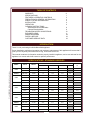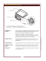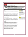
1
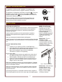
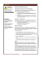
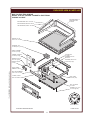
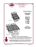
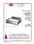
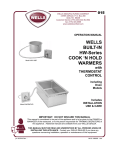
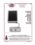
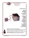
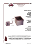
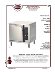
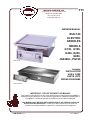
111
WELLS BLOOMFIELD, LLC
10 Sunnen Dr., St. Louis, MO 63143
telephone: 800-807-9054
fax: 314-781-2714
www.wells-mfg.com
OWNERS MANUAL
BUILT-IN
ELECTRIC
GRIDDLES
MODELS
G136, G196,
G236, G246,
G606,
JG246UL, PG196
Model G136
Includes
INSTALLATION
USE & CARE
PARTS LISTS
WIRING DIAGRAMS
Model JG246UL
IMPORTANT: DO NOT DISCARD THIS MANUAL
This manual is considered to be part of the appliance and is to be given to the OWNER or
MANAGER of the restaurant, or to the person responsible for TRAINING OPERATORS of
this appliance. Additional manuals are available from your WELLS DEALER.
THIS MANUAL MUST BE READ AND UNDERSTOOD BY ALL PERSONS USING OR
INSTALLING THIS APPLIANCE. Contact your WELLS DEALER if you have any
questions concerning installation, operation or maintenance of this equipment.
p/n 2M-303340 Rev. D
M101
091229
LIMITED WARRANTY STATEMENT
Unless otherwise specified, all commercial cooking
equipment manufactured by WELLS BLOOMFIELD, LLC is
warranted against defects in materials and workmanship for
a period of one year from the date of original installation or
18 months from the date of shipment from our factory,
whichever comes first, and is for the benefit of the original
purchaser only.
THIS WARRANTY IS THE COMPLETE AND ONLY
WARRANTY, EXPRESSED OR IMPLIED IN LAW OR IN
FACT, INCLUDING BUT NOT LIMITED TO, WARRANTIES
OF MERCHANTABILITY OR FITNESS FOR ANY
PARTICULAR PURPOSE, AND/OR FOR DIRECT,
INDIRECT OR CONSEQUENTIAL DAMAGES IN
CONNECTION WITH WELLS BLOOMFIELD PRODUCTS.
This warranty is void if it is determined that, upon inspection
by an authorized service agency, the equipment has been
modified, misused, misapplied, improperly installed, or
damaged in transit or by fire, flood or act of God. It also
does not apply if the serial nameplate has been removed, or
if service is performed by unauthorized personnel. The
prices charged by Wells Bloomfield for its products are
based upon the limitations in this warranty. Seller’s
obligation under this warranty is limited to the repair of
defects without charge by a Wells Bloomfield factory
authorized service agency or one of its sub-service
agencies. This service will be provided on customer’s
premises for non-portable models. Portable models (a
device with a cord and plug) must be taken or shipped to
the closest authorized service agency, transportation
charges prepaid, for service. In addition to restrictions
contained in this warranty, specific limitations are shown in
the Service Policy and Procedure Guide. Wells Bloomfield
authorized service agencies are located in principal cities.
This warranty is valid in the United States and Canada and
void elsewhere. Please consult your classified telephone
directory, your foodservice equipment dealer or contact:
Wells Bloomfield, LLC
10 Sunnen Dr., St. Louis MO 63143 USA
phone (314) 781-2777 or fax (314) 781-2714
for information and other details concerning warranty.
SERVICE POLICY AND PROCEDURE GUIDE and ADDITIONAL WARRANTY EXCLUSIONS
1.
2.
3.
4.
6.
cleaning schedules, are customer responsibility. Those
miscellaneous adjustments noted are customer
responsibility. Proper attention to preventative
maintenance and scheduled maintenance procedures
will prolong the life of the appliance.
7. Travel mileage is limited to sixty (60) miles from an
Authorized Service Agency or one of its sub-service
agencies.
8. All labor shall be performed during regular working
hours. Overtime premium will be charged to the buyer.
9. All genuine Wells replacement parts are warranted for
ninety (90) days from date of purchase on nonwarranty equipment. This parts warranty is limited only
to replacement of the defective part(s). Any use of
non-genuine Wells parts completely voids any
warranty.
10. Installation, labor, and job check-outs are not
considered warranty and are thus not covered by this
warranty.
11. Charges incurred by delays, waiting time or operating
restrictions that hinder the service technician’s ability to
perform service are not covered by warranty. This
includes institutional and correctional facilities.
SHIPPING DAMAGE CLAIM PROCEDURE
NOTE: For your protection, please note that equipment in
this shipment was carefully inspected and packaged by
skilled personnel before leaving the factory. Upon
acceptance of this shipment, the transportation company
assumes full responsibility for its safe delivery.
IF SHIPMENT ARRIVES DAMAGED:
1. VISIBLE LOSS OR DAMAGE: Be certain that any
visible loss or damage is noted on the freight bill or
express receipt, and that the note of loss or damage is
signed by the delivery person.
2. FILE CLAIM FOR DAMAGE IMMEDIATELY:
Regardless of the extent of the damage.
3.
CONCEALED LOSS OR DAMAGE: if damage is
unnoticed until the merchandise is unpacked, notify the
transportation company or carrier immediately, and file
“CONCEALED DAMAGE” claim with them. This
should be done within fifteen (15) days from the date
the delivery was made to you. Be sure to retain the
container for inspection.
Wells Bloomfield cannot assume liability for damage or loss
incurred in transit. We will, however, at your request, supply
you with the necessary documents to support your claim.
xi
111 p/n 2M-303340 OpManual Built-In Electric Griddles
5.
Resetting of safety thermostats, circuit breakers, over
load protectors, and/or fuse replacements are not
covered by this warranty unless warranted conditions
are the cause.
All problems due to operation at voltages or phase
other than specified on equipment nameplates are
not covered by this warranty.
Conversion to correct voltage and/or phase must be
the customer’s responsibility.
All problems due to electrical connections not made
in accordance with electrical code requirements
and wiring diagrams supplied with the equipment are
not covered by this warranty.
Replacement of items subject to normal wear, to
include such items as knobs, light bulbs; and, normal
maintenance functions including adjustments of
thermostats, adjustment of micro switches and
replacement of fuses and indicating lights are not
covered by warranty.
Damage to electrical cords and/or plug due to exposure
to excessive heat are not covered by this warranty.
Full use, care, and maintenance instructions supplied
with each machine. Noted maintenance and
preventative maintenance items, such as servicing and
TABLE OF CONTENTS
WARRANTY
SPECIFICATIONS
FEATURES & OPERATING CONTROLS
PRECAUTIONS & GENERAL INFORMATION
AGENCY LISTING INFORMATION
INSTALLATION
OPERATION
CLEANING INSTRUCTIONS
Standard and GroovedGriddles
Chrome-Plated griddles
TROUBLESHOOTING SUGGESTIONS
EXPLODED VIEWS
WIRING DIAGRAMS
PARTS & SERVICE
CUSTOMER SERVICE DATA
xi
1
2
3
4
4
6
8
9
10
11
24
33
33
INTRODUCTION
Thank You for purchasing this Wells Bloomfield appliance.
Proper installation, professional operation and consistent maintenance of this appliance will ensure that it
gives you the very best performance and a long, economical service life.
This manual contains the information needed to properly install this appliance, and to use and care for the
appliance in a manner which will ensure its optimum performance.
SPECIFICATIONS - STANDARD GRIDDLES
AMPS 3ø
MODEL
VOLTS
WATTS
L1
L2
L3
N
AMPS
1ø
208/240V
6,750 / 9,000
14.0 / 18.7
28.1 / 32.5
14.0 / 18.7
32.5 / 37.5
480
9,000
9.4
16.2
9.4
18.7
380-415V
10,800
15
15.0
15.0
208V
12,000
28.8
49.9
28.8
57.6
240V
12,000
25.0
43.3
25.0
50.0
480V
12,000
12.5
21.7
12.5
25.0
380-415V
16,100
22.5
22.5
225.
208V
16,000
48.3
51.3
35.0
76.9
240V
16,000
41.7
44.4
30.4
66.6
480V
16,000
20.9
22.2
15.5
33.3
380-415V
16,000
15.8
31.6
19.2
208V
21,500
63.4
67.1
45.8
103.3
240V
21,500
55.0
58.3
39.6
89.5
480V
21,500
27.1
28.9
19.9
43.8
380-415V
21,000
20.8
41.7
25.0
208V
32,000
48.3
51.3
35.0
76.9 x 2
240V
32,000
41.7
44.4
30.4
66.6 x 2
480V
32,000
20.9
22.0
15.1
33.3 x 2
111 p/n 2M-303340
OpManual Built-In Electric Griddles
G136
G136EU
G196
G196EU
G236
G236EU
G246
G246EU
G606
1
0.0
0.0
38.6
50.6
FEATURES & OPERATING CONTROLS
SPLASHGUARD
GREASE TROUGH
NAMEPLATE
HEATING
INDICATOR
GREASE DRAWER
TEMPERATURE
CONTROL
KNOB
Fig. 1 Countertop Griddle Features & Operating Controls
G136 Shown - G196, G236, G246 and G606 are Similar
TEMPERATURE
CONTROL
Power is applied to the heating elements according to the control knob
position and the actual temperature sensed at the thermobulb. When
the element is energized the heating indicator will glow.
Each section of the griddle is individually controllable.
GREASE TROUGH
Extra-wide trough with radiused corners for easier cleaning. Trough
slopes toward a large waste hole that empties into the removable
grease drawer.
GREASE DRAWER
Large-capacity drawer is removable through the front for easy cleaning.
REMOVABLE SPLASH
GUARD
Stainless steel aplash guard simplifies griddle maintenance and helps
to keep grease from splattering onto adjacent walls and equipment
NAMEPLATE
Lists manufacturer’s information, model and serial number. Also lists
electrical specifications.
2
111 p/n 2M-303340 OpManual Built-In Electric Griddles
Dial position is an indication of the temperature setting. The actual
temperature at the griddle surface will vary, depending upon the initial
type and temperature of the product, and other variables.
PRECAUTIONS AND GENERAL INFORMATION
DANGER: BURN HAZARD
Contact with cooking surface cause severe burns. Always wear protective clothing
and avoid contact with griddle surface.
WARNING: ELECTRIC SHOCK HAZARD
All servicing requiring access to non-insulated components must be performed by
qualified service personnel. DO NOT open any access panel that requires the use
of tools. Failure to heed this warning may result in severe electric shock.
This appliance is intended for use in commercial establishments
only.
This appliance is intended to prepare food for human consumption.
No other use is recommended or authorized by the manufacturer or its
agents.
Operators of this appliance must be familiar with the appliance use,
limitations and associated restrictions. Operating instructions must be
read and understood by all persons using or installing this appliance.
Cleanliness of this appliance is essential to good sanitation. Read and
follow all included cleaning instructions and schedules to ensure the
safety of the food product.
Disconnect this appliance from electrical power before performing any
maintenance or servicing.
DO NOT submerge this appliance in water. This appliance is not jet
stream approved. Do not direct water jet or steam jet at this appliance,
or at any control panel or wiring. Do not splash or pour water on, in or
over any controls, control panel or wiring.
111 p/n 2M-303340
OpManual Built-In Electric Griddles
Exposed surfaces of this appliance can be hot to the touch and may
cause burns.
The technical content of this manual, including any wiring diagrams,
schematics, parts breakdown illustrations and/or adjustment
procedures, is intended for use by qualified technical personnel.
Any procedure which requires the use of tools must be performed by a
qualified technician.
This manual is considered to be a permanent part of the appliance.
This manual and all supplied instructions, diagrams, schematics, parts
breakdown illustrations, notices and labels must remain with the
appliance if it is sold or moved to another location.
This appliance is made in the USA. Unless otherwise noted, this
appliance has American sizes on all hardware.
3
CAUTION:
RISK OF
DAMAGE
DO NOT connect or energize
this appliance until all
installation instructions are
read and followed. Damage
to the appliance will result if
these instructions are not
followed.
CAUTION:
HOT SURFACE
Exposed surfaces can be hot
to the touch and may cause
burns.
AGENCY LISTING INFORMATION
This appliance conforms to NSF Standard 4 for sanitation only if
installed in accordance with the supplied Installation Instructions.
This appliance is Underwriters Laboratory recognized ( ). Since this
appliance is only a single component of a complete installation, the
finished installation of this
unit requires additional evaluations to
Underwriters Laboratory standards.
STD 4
Refer to Installation Instructions included with the appliance for
Underwriters Laboratories conditions of acceptability, electrical
requirements and other installation concerns.
INSTALLATION
UNPACKING & INSPECTION
Carefully remove the appliance from the carton. Remove all protective
plastic film, packing materials and accessories from the appliance
before connecting electrical power or otherwise performing any
installation procedure.
Carefully read all instructions in this manual and the Installation
Instruction Sheet packed with the appliance before starting any
installation.
Read and understand all attached labels and diagrams.
Carefully account for all components and accessories before discarding
packing materials. Store all accessories in a convenient place for later
use.
CUT-OUT AND INSTALLATION
IMPORTANT: This is a
GENERAL GUIDE.
For specific equipment and
cutout dimensions, and other
installation details, refer to the
Installation Instructions
supplied with the appliance.
Mounting the griddle:
a. Verify that provided sealants are applied to the under side of
the griddle top flange prior to setting the unit into the cutout.
b. After installation, verify that the tabs on the Wellsloks are
turned out to lock the appliance into the counter (see Fig. 2).
c. Apply a thin bead of food-grade silicone sealant around the
flange to seal it to the counter.
Refer to the Installation Instructions for required clearances. Maintain
required clearances between the appliance and adjacent combustible
and non-combustible surfaces.
Sufficient overhead clearance must be provided to allow the element
assembly to be raised. Refer to the Installation Instruction Sheet for
required clearances.
Avoid storing flammable or combustible materials near the appliance.
This includes gasoline and other fuels, mops, rags and wrapping paper.
4
Fig. 2 Set the Wellslloks
IMPORTANT: Water damage
caused by failure to set
Wellsloks, failure to install
gasket, or failure to seal
flange to counter is NOT
covered by warranty.
111 p/n 2M-303340 OpManual Built-In Electric Griddles
Cutouts
a. Griddles may be installed in METAL COUNTERS ONLY.
b. Cutout dimensions for griddles and control panels are listed on
the Installation Instructions provided with the griddle.
c. Refer to the Installation Instructions for Underwriters
Laboratories Conditions of Acceptability.
NOTE: DO NOT discard
the carton or other packing
materials until you have
inspected the appliance for
hidden damage and tested it
for proper operation.
Refer to SHIPPING DAMAGE
CLAIM PROCEDURE on the
inside front cover of this
manual.
INSTALLATION (continued)
WARNING: ELECTRIC SHOCK HAZARD
All servicing requiring access to non-insulated electrical components must be performed by a
factory authorized technician.
DO NOT open any access panel which requires the use of tools. Failure to follow this warning
can result in severe electrical shock.
CAUTION:
ELECTRICAL INSTALLATION
Refer to the nameplate. Verify the electrical service power. Voltage
and phase must match the nameplate specifications. Connecting the
griddle to the wrong voltage can severely damage the unit or cause
noticeably decreased performance.
IMPORTANT: Damage due to being connected to the wrong voltage is
NOT covered by warranty.
Use copper wire suitable for at least 90ºC for supply connections.
Griddles are factory wired three-phase (3ø).
For single-phase (1ø) wiring, refer to the wiring diagram attached to the
griddle.
This griddle is not fused. Protect the circuit with properly sized fuses or
circuit breaker.
An electrical disconnect must be installed readily accessible to the
operator of the griddle.
RISK OF
DAMAGE
DO NOT connect or energize
this appliance until all
installation instructions are
read and followed. Damage
to the appliance will result if
these instructions are not
followed.
CAUTION:
ELECTRIC
SHOCK HAZARD
This griddle must be
electrically grounded.
Connect the terminal marked
“GND” or “
”
to a suitable building ground.
Install splashguard. Notches on front wings lock into exposed studs in
grease trough.
Slide grease drawer into grease drawer sleeve in front of griddle.
111 p/n 2M-303340
OpManual Built-In Electric Griddles
EQUIPMENT SETUP
5
IMPORTANT:
Damage due to being
connected to the wrong
voltage or phase is NOT
covered by warranty.
OPERATION
CAUTION:
HOT SURFACE
PREPARING THE GRIDDLE SURFACE
SEASONING STANDARD AND GROOVED GRIDDLES
Exposed surfaces can be
very hot and may cause
severe burns on contact.
As manufactured, the steel surface of your Wells griddle has
microscopic pores. It is important to fill these pores with oil in order
to provide a hard, non-stick cooking surface.
a. Preheat griddle surface to 375ºF (191ºC).
b. Spread a light film of cooking oil over entire griddle surface.
c. Allow oil film to “cook in” for approximately 2 minutes, or until
it smokes.
d. Wipe griddle surface with clean damp cloth to remove all oil.
e. For new griddles, repeat this procedure 2-3 times until griddle
has a slick, clean surface.
IMPORTANT:
SCRATCHES WILL
DAMAGE THE SURFACE
OF CHROME-PLATED
GRIDDLES.
CHROME PLATED GRIDDLES
DO NOT use anything on
chrome griddle that could
scratch the surface.
DO NOT clean chrome
surface with griddle bricks,
pumice stone or abrasive
cleansers.
Because the microscopic pores in the griddle surface are filled by the
chrome plating, no seasoning of the griddle surface is required.
a. Thoroughly clean griddle surface using a soft clean cloth and a
small amount of mild detergent.
b. Rinse and dry thoroughly after cleaning.
c. The griddle is now ready to use.
USING THE GRIDDLE
Check the chart on page 7 for recommended cooking temperatures.
Turn temperature control knob to the desired temperature. The heating
indicator light will glow while the griddle is heating. When the indicator
light first goes out, griddle is ready to use.
For standard griddles:
•
•
•
For chrome plated griddles:
•
•
Scrape cooking waste into the grease trough after preparing each
order.
DO NOT bang or tap pots, pans, spatulas or other metal utensils on
the griddle surface as this may damage the chrome plating.
NOTE:
Separate sections of griddle may be set to different temperatures.
This will allow a variety of products to be prepared at the same time,
and will allow prepared product to be held at serving temperature after
cooking.
For best results, different temperatures should be set from coolest to
hottest sequentially across the width of the griddle. (Heat will migrate
over the entire griddle surface. Setting one section low, adjacent to a
section set high, may overwork components in the “high” section as the
thermostat tries to compensate for heat lost to the “low” section.)
Teppan griddle JG-246UL heats in the center two quadrants only. The
outer two quadrants are used for holding prepared food at temperature.
6
111 p/n 2M-303340 OpManual Built-In Electric Griddles
Keep the griddle surface clean and well oiled during use.
Scrape cooking waste into the grease trough frequently during use.
Occasionally brush or spray a light coat of cooking oil on the griddle
surface in order to maintain the non-stick surface.
OPERATION (continued)
RECOMMENDED GRILLING TIMES AND TEMPERATURES
PRODUCT
TEMP ºF
TIME
Sausage, link and patty
350º
3 minutes
Bacon
350º
2 - 3 minutes
Canadian Bacon
350º
2 - 3 minutes
375º
3 - 4 minutes
Broiled Ham
375º
2 minutes
Beef Tenderloin
400º
3 - 4 minutes
Minute Steaks
400º
3 - 4 minutes
Club Steak, 1” thick
400º
3 - 5 minutes
Hamburgers
350º
3 - 4 minutes
Cheeseburgers
350º
3 - 4 minutes
Melted Cheese Sandwich
375º
3 - 4 minutes
Hot Dogs
325º
2 - 3 minutes
111 p/n 2M-303340
OpManual Built-In Electric Griddles
Ham Steaks
7
NOTE:
The times and temperatures
in this chart are suggestions
only.
Your own experience
with your own menu items
will be your best guide to
achieving the best food
product.
CLEANING INSTRUCTIONS - STANDARD AND GROOVED GRIDDLES
CAUTION:
PREPARATION
Set temperature control to 220ºF. Allow
griddle temperature to drop to 220ºF before
proceeding.
FREQUENCY
Daily
TOOLS
Griddle Brick or Pumice Stone, Fiber Brush
Plastic Scouring Pad, Plastic Scraper
Contoured Scraper (grooved griddle)
Mild Detergent, Non-Abrasive Cleanser
Clean Soft Cloth / Sponge
BURN HAZARD
Griddle will be hot during
portions of this cleaning
procedure.
Always heat-protective gloves
and apron.
CAUTION:
ELECTRIC
SHOCK HAZARD
Do not submerge griddle in
water.
IMPORTANT: DO NOT spill
or pour water into controls,
control panel or wiring.
DO NOT submerge griddle in
water. Damage to internal
components will occur.
Damage to internal
components from water
damage is not covered by
warranty.
IMPORTANT: DO NOT use
steel wool or abrasive
cleansers for cleaning the
griddle cabinet.
Pour a small amount of water on the griddle surface and let it “sizzle”.
Clean the griddle surface:
a. For standard griddles, use a pumice stone or griddle brick to
scrape food waste. Clean the griddle surface down to bright
metal. Wipe off any remaining powder residue.
b. For grooved-surface griddles, use the supplied contoured
scraper to scrape food waste. Clean the griddle surface down
to bright metal.
Use a soft-bristled fiber brush in a circular motion to remove any
remaining food particles.
Turn temperature control to OFF. Allow the griddle surface to cool,
then wipe the surface with a clean cloth. Dry the griddle surface
thoroughly.
IMPORTANT: SEASON THE COOKING SURFACE AFTER EACH
CLEANING. Refer to page 6.
At least once each day, the grease trough must be thoroughly cleaned.
Using a scraper, remove all grease and food waste from the grease
trough by pushing it down the waste hole and into the grease drawer.
After scraping all cooking waste from grease trough into the grease
drawer, take the grease drawer to kitchen cleaning area and properly
dispose of all waste.
a. Clean drawer with hot water and a mild detergent.
b. Dry drawer thoroughly and reinstall in griddle.
Clean the splash guard in the sink with warm water and mild detergent,
or in the dishwasher. Rinse thoroughly and reinstall.
Wipe down exterior of griddle and control panel with a clean cloth and
non-abrasive cleanser. Rinse thoroughly with a clean cloth dampened
with water. Dry with a soft clean cloth
Procedure is complete.
8
111 p/n 2M-303340 OpManual Built-In Electric Griddles
IMPORTANT: NEVER USE
STEEL WOOL TO CLEAN
THE GRIDDLE SURFACE!
DO NOT use detergent or
oven cleaner to clean the
griddle surface.
CLEANING
CLEANING INSTRUCTIONS - CHROME PLATED GRIDDLES
PREPARATION
Set temperature control to 220ºF. Allow
griddle temperature to drop to 220ºF before
proceeding.
FREQUENCY
Daily
TOOLS
4” Razor-Style Scraper, Soft Bristle Brush
Mild Detergent, Non-Abrasive Cleanser
Clean Soft Cloth / Sponge
Pour a small amount of water on the griddle surface and let it “sizzle”.
Use a 4” razor-style scraper to clean the remaining food particles from
the griddle surface
IMPORTANT: NEVER USE GRIDDLE BRICKS, PUMICE STONES
OR STEEL WOOL TO CLEAN THE GRIDDLE SURFACE!
DO NOT use detergent or oven cleaner to clean griddle surface.
IMPORTANT: NEVER BANG OR TAP METAL IMPLEMENTS,
SPATULAS, POTS, PANS, OR SCRAPERS ON THE GRIDDLE
SURFACE!
Use a soft-bristled fiber brush in a circular motion to remove any
remaining food particles.
Turn temperature control to OFF. Allow the griddle surface to cool,
then wipe the surface with a clean cloth. Dry the griddle surface
thoroughly.
OpManual Built-In Electric Griddles
BURN HAZARD
Griddle will be hot during
portions of this cleaning
procedure.
Always heat-protective gloves
and apron.
CAUTION:
CLEANING
111 p/n 2M-303340
CAUTION:
At least once each day, the grease trough must be thoroughly cleaned.
Using a scraper, remove all grease and food waste from the grease
trough by pushing it down the waste hole and into the grease drawer.
After scraping all cooking waste from grease trough into the grease
drawer, take the grease drawer to kitchen cleaning area and properly
dispose of all waste.
a. Clean drawer with hot water and a mild detergent.
b. Dry drawer thoroughly and reinstall in griddle.
Clean the splash guard in the sink with warm water and mild detergent,
or in the dishwasher. Rinse thoroughly and reinstall.
Wipe down exterior of griddle and control panel with a clean cloth and
non-abrasive cleanser. Rinse thoroughly with a clean cloth dampened
with water. Dry with a soft clean cloth
Procedure is complete.
9
ELECTRIC
SHOCK HAZARD
Do not submerge griddle in
water.
IMPORTANT: DO NOT spill
or pour water into controls,
control panel or wiring.
DO NOT submerge griddle in
water. Damage to internal
components will occur.
Damage to internal
components from water
damage is not covered by
warranty.
IMPORTANT: DO NOT use
griddle bricks, steel wool or
abrasive cleansers to clean
chrome-plated cooking
surface.
IMPORTANT: DO NOT use
steel wool or abrasive
cleansers for cleaning the
griddle cabinet .
IMPORTANT:
Never bang or tap metal
implements, spatulas, pots,
pans or scrapers on the
griddle surface.
TROUBLESHOOTING SUGGESTIONS
DESCRIPTION
POSSIBLE PROBLEM
SUGGESTED REMEDY
Griddle will not heat
Circuit breaker off or tripped
Reset circuit breaker
Temperature control knobs not set to
desired temperature
Set to desired temperature
Damaged internal component
Contact Wells Authorized Service
Agency for repairs
Grease drawer full or not installed
Empty grease drawer.
Install properly
Damaged internal component
Contact Wells Authorized Service
Agency for repairs
One section does not
heat
Griddle drips grease
NOTE: There are no user serviceable components in the griddle. In all
cases of damage or malfunction, contact your Authorized Wells Service
Agency for repairs.
111 p/n 2M-303340 OpManual Built-In Electric Griddles
10
EXPLODED VIEW & PARTS LIST
BUILT-IN ELECTRIC GRIDDLE
MODEL G136 w/o TROUGH - CABINET & ELECTRICAL
208/240V and 480V
SPLASHGUARD G-13
COMPLETE ASSY
5G-20632
SPLASHGUARD LEFT G7-35781
SPLASHGUARD, REAR G7-34437
SPLASHGUARD, RIGHT G7-35780
SEALANT, G-136
5/16” x 96” 1P-33308
SLEEVING, 5/16”
1O-32040 (6” rl) (2 reqd)
SHIELD, THERMO
2A-31974 (2 reqd)
OUTLET BOX
G7-31997
TERMINAL BLOCK
WS-50131
THERMO, CONTROL
2T-30257 (2 reqd)
SCREW, 6-32x3/16
2C-31718 (pk10)
BUSHING, HEYCO 7/8”
2K-31040 (2 reqd)
KNOB 2R-30259
(2 reqd)
NUT, HEX ALUMINUM
8-32 x 7/8” 2C-41974
COVER, OUTLET
BOX G7-32005
TAPE, CORK
1P-36178 (15’rl)
NUT, 8-32 KEPS
2C-31053
111 p/n 2M-303340
SCREW, 8-32 x 2-1/2”
2C-31734 (pk100)
WE
LL
S
OFF
23
0
205
65
WELLS
18
0
150
120
OpManual Built-In Electric Griddles
LIGHT, SIGNAL
AMBER 2J-30516
95
KNOB 2R-30259
G136 W/O TROUGH SVC/N
IL1907 PL111
11
EXPLODED VIEW & PARTS LIST
BUILT-IN ELECTRIC GRIDDLE
MODEL G-136 - HEATING ELEMENTS
208/240V and 480V
INSULATION PAD
2H-36051 (pk 2'x4')
COVER, GREASE
DRAWER G7-31995
NUT, 1/4-20 HEX Ni
2C-31253
CLAMP, THERMO
BULB G7-32028
CLIP, TIE-DOWN INSULATION
G7-33474
TUBE, THERMO
BULB 18" 2A-31972
CLAMP, ELEMENT
END G7-31969
CLAMP, ELEMENT
CENTER G7-31968
JUMPER, ELEMENT
SHORT 2E-32054
ELEMENT 2250W
240V 2N-30496UL
480V 2N-48904UL
T
ON
FR
GRIDDLE (REF.)
shown inverted
ELECTRIC GRIDDLE G-136
HEATING ELEMENTS
20054 208/240V 3ø
20054A 208/240V 3ø (without trough)
20215 480V 3ø
IL1908
12
PL111
111 p/n 2M-303340 OpManual Built-In Electric Griddles
NUT, 10-32
HEX 2C-35313
EXPLODED VIEW & PARTS LIST
BUILT-IN ELECTRIC GRIDDLE
MODEL G-136 - CABINET & ELECTRICAL
208/240V and 480V
SPLASHGUARD LEFT G7-55781
SPLASHGUARD G-13
COMPLETE ASSY
5G-20632
SPLASHGUARD, REAR G7-34437
SPLASHGUARD, RIGHT G7-35780
GRIDDLE PLATE
ASSEMBLY WS-51476
SEALANT, G-136
5/16” x 96” 1P-33308
SLEEVING, 5/16”
1O-32040 (6” rl) (2 reqd)
SHIELD, THERMO
1O-51974, (2 reqd)
OUTLET BOX
G7-31997
TERMINAL BLOCK KIT 3-POLE
WS-50131
THERMO, CONTROL
2T-30257 (2 reqd)
SCREW, 6-32X3/16
2C-31718
BUSHING, HEYCO 7/8”
WS-31040 (2 reqd)
KNOB 2R-30259
(2 reqd)
LIGHT, SIGNAL AMBER
208/240V 2J-30516
480V
2J-40436
FRONT PANEL
G7-31025
NUT , 8-32 KEPS
2C-31053
SCRE W, 8-3 2 x 2-1/2”
2C-31734
HANDLE
2R-38668
W
EL
LS
SHROUD, GREASE DRAWER
WS-51989
OF F
23
0
205
65
WELLS
SCREW 6ABx5/16
2C-33935
0
95
GREASE TRAY ASSY
COMPLETE WS-50279
12 0
TRAY FRONT
G7-Z12047
18
111 p/n 2M-303340
TAPE, CORK
1P-36178 (15’rl)
COVER, OUTLET
BOX G7-32005
15 0
OpManual Built-In Electric Griddles
NUT , H EX ALUMINUM
8-3 2 x 7/8” 2C-41974
KNOB 2R-50259
MODEL G136 CABINET & ELECTRICAL
208/240V and 480V
13
IL1909 PL111
EXPLODED VIEW & PARTS LIST
BUILT-IN ELECTRIC GRIDDLE
MODEL G196 - HEATING ELEMENTS
208V, 240V and 480V
INSULATION PAD
2H-36051 (pk 2'x4')
COVER, GREASE
DRAWER G7-31995
CLIP, INSULATION
G7-33474 (11 ea)
CLAMP, THERMO
G7-32028 (4 ea)
TUBE, THERMO
2A-31972 (2 ea)
NUT, 1/4-20 HEX Ni
2C-31253 (36 ea)
CLAMP, ELEM CENTER
G7-31968 (10 ea)
CLAMP, ELEM END
G7-32038 (8 ea)
JUMPER, LONG
2E-32055 (4 ea)
HEATING ELEMENT
2N-30511UL (208V)
2N-30512UL (240V) (4 ea)
2N-48902UL (480V)
T
ON
FR
GRIDDLE
SHOWN INVERTED
(ref.)
MODEL G196 HEATING ELEMENTS
208/240V and 480V
IL1910 PL111
14
111 p/n 2M-303340 OpManual Built-In Electric Griddles
NUT, 10-32 HEX
2C-35313 (16 ea)
EXPLODED VIEW & PARTS LIST
BUILT-IN ELECTRIC GRIDDLE
MODEL G196 - CABINET & ELECTRICAL
208V, 240V and 480V
SPLASHGUARD, LEFT G7-35781
SPLASHGUARD G-19
COMPLETE ASSY
5G-20634
SPLASHGUARD, REAR G7-34436
SPLASHGUARD, RIGHT G7-35780
GRIDDLE PLATE ASSY
WS-55665
SEALANT 5/16”x132”
1P-33309
LIGHT, SIGNAL AMBER
2J-30516 (208/240V)
2J-40436 (480V)
(2 ea)
SHIELD, THERMO
2A-31974 (2 reqd)
TERMINAL BLOCK
WS-50131
NUT, HEX ALUMINUM
8-32 x 7/8” 2C-61974
BUSHING, HEYCO 7/8”
2K-31040
SLEEVING, 5/16”
1O-52040 (6” rl) (2 reqd)
THERMO, CONTROL
2T-30257 (2 reqd)
TAPE, CORK
1P-36178 (15’rl)
SCREW, 6-32x3/16
2C-31718
KNOB (2 reqd)
2R-30259
111 p/n 2M-303340
OpManual Built-In Electric Griddles
OUTLET BOX
G7-31997
COVER, OUTLET
BOX G7-52005
NUT, 8-32 KEPS
2C-31053
HANDLE
2R-38668
SCREW, 8-32 x 2-1/2”
2C-31734
WE
SHROUD, GREASE
DRAWER WS-51989
LL
S
TRAY FRONT
G7-Z12047
GREASE TRAY ASSY
COMPLETE WS-50279
IL1911 PL111
ELECTRIC GRIDDLE G-196
CABINET COMPONENTS
15
EXPLODED VIEW & PARTS LIST
BUILT-IN ELECTRIC GRIDDLE
MODEL G-236 - HEATING ELEMENTS
208V, 240V and 480V
INSULATION PAD
2H-36051 (pk 2'x4')
COVER, GREASE
DRAWER G7-31995
CLIP, INSULATION
G7-33474 (12 ea)
CLAMP, THERMO
G7-32028 (12 ea)
CLAMP, PERIMETER
ELEMENT RIGHT
G7-32026
TUBE, THERMO
2A-31971 (4 ea)
NUT, 1/4-20 HEX Ni
2C-31253 (36 ea)
CLAMP, ELEM END
G7-32038 (8 ea)
NUT, 10-32
HEX 2C-35313
CLAMP, ELEM CENTER
DD-32037 (10 ea)
CLAMP, PERIMETER
ELEMENT CENTER
G7-32025
HEATING ELEMENT (4 ea)
3800W / 208V 2N-30510UL
3800W / 240V 2N-30509UL
3800W / 480V 2N-31428UL
CLAMP, PERIMETER
ELEMENT LEFT G7-32027
HEATING ELEMENT, PERIMETER
800W / 208/240V 2N-30508UL
800W / 480V 2N-31495UL
T
ON
FR
ELECTRIC GRIDDLE G-236
HEATING ELEMENTS
IL1912 PL111
16
111 p/n 2M-303340 OpManual Built-In Electric Griddles
GRIDDLE
SHOWN INVERTED
(ref.)
EXPLODED VIEW & PARTS LIST
BUILT-IN ELECTRIC GRIDDLE
MODEL G-236 - CABINET & ELECTRICAL
208V, 240V and 480V
SPLASH GUARD ASSY, G-236
COMPLETE
5G-20635
SPLASHGUARD, LEFT G7-35783
SPLASHGUARD, RIGHT G7-35782
GRIDDLE PLATE
ASSEMBLY
WS-51490
SEALANT 5/15” x 132”
1P-33309
SLEEVING, 5/16”
1O-32040 (6” rl) (4 reqd)
SHIELD, THERMO
2A-31974 (4 reqd)
LIGHT, SIGNAL AMBER
208 / 240 V 2J-30516
480V
2J-40436
(4 reqd)
THERMO, CONTROL
2T-30257 (4 ea)
OUTLET BOX
G7-31997
TERMINAL BLOCK
2E-30412
NUT, HEX ALUMINUM
8-32 x 7/8” 2C-41974
BUSHING, HEYCO 7/8”
2K-31040
KNOB (4 reqd)
2R-30259
TAPE, CORK
1P-36178 (1’ rl)
SCREW, 6-32x3/16
2C-31718
111 p/n 2M-303340
OpManual Built-In Electric Griddles
COVER, OUTLET
BOX G7-32005
TRAY FRONT
G7-Z12047
SHROUD, GREASE
DRAWER WS-51989
W
EL
NUT, 8-32 KEPS
2C-31053
SCREW, 8-32 x 2-1/2”
2C-31734
LS
HANDLE
2R-38668
GREASE DRAWER
COMPLETE ASSY
WS-50279
KNOB 2R-30259
IL1913 PL111
17
EXPLODED VIEW & PARTS LIST
BUILT-IN ELECTRIC GRIDDLE
MODEL G-246 - HEATING ELEMENTS
208V, 240V and 480V
INSULATION PAD
2H-36051 (8 sf) (pk 2'x4')
COVER, GREASE
DRAWER G7-31995
CLIP, INSULATION
G7-33474 (16 ea)
NUT, 1/4-20 HEX
2C-31253 (64 ea)
CLAMP, THERMO BULB
GRIDDLE G7-32028(12 ea)
TUBE, THERMO 24"
2A-31971 (4 ea)
NUT, 10-32 HEX
2C-35313 (36 ea)
JUMPER, SHORT
2E-32054 (8 ea)
CLAMP, ELEM LF
G7-32027
CLAMP, ELEM END
G7-31969 (16 ea)
CLAMP, ELEM
G7-45254
CLAMP, ELEM
PERIM G7-32025
(8 ea)
CLAMP, ELEM RT
G7-32027
ELEMENT (8ea)
208V 2500W 2N-30513UL
240V 2500W 2N-30520UL
480V 2500W 2N-48903UL
ELEM, PERIM
240V 1000W 2N-30507UL
480V 1000W 2N-31498UL
T
ON
FR
ELECTRIC GRIDDLE G-246
HEATING ELEMENTS
IL1914 PL111
18
111 p/n 2M-303340 OpManual Built-In Electric Griddles
GRIDDLE
SHOWN INVERTED
(ref.)
EXPLODED VIEW & PARTS LIST
BUILT-IN ELECTRIC GRIDDLE
MODEL G-246 - CABINET & ELECTRICAL
208V, 240V and 480V
SPLASHGUARD, LEFT G7-35783
SPLASH GUARD ASSY, G-24
COMPLETE
5G-20636
SPLASHGUARD, RIGHT G7-35782
GRIDDLE PLATE
ASSEMBLY
DD-35667
SEALANT 5/15” x 160”
1P-33310
SLEEVING, 5/16”
1O-32040 (6” rl) (4 reqd)
SHIELD, THERMO
2A-31974 (4 reqd)
THERMO, CONTROL
2T-30257 (4 ea)
LIGHT, SIGNAL AMBER
208 / 240 V 2J-30516
480V
2J-40436
(4 reqd)
TERMINAL BLOCK
2E-31276
SCREW, 6-32x3/16
2C-31718 (pk10)
BUSHING, HEYCO 7/8”
2K-31040 (2 ea)
TAPE, CORK
1P-36178 (2” x 1’ rl)
NUT, 8-32 KEPS
2C-31053 (2 ea)
TRAY FRONT
G7-Z12047
111 p/n 2M-303340
OpManual Built-In Electric Griddles
KNOB
2R-30259 (4 reqd)
SHROUD, GREASE
DRAWER WS-51989
W
EL
SCREW, 8-32 x 2-1/2”
2C-31734 (2 ea)
LS
HANDLE
2R-38668
GREASE DRAWER
COMPLETE ASSY
G7-35782
KNOB 2R-30259
IL1915 PL111
19
EXPLODED VIEW & PARTS LIST
BUILT-IN ELECTRIC GRIDDLE
MODEL G-606 - HEATING ELEMENTS
208V, 240V and 480V
COVER, GREASE DRAWER
(2 ea) G7-31995
INSULATION PAD
2H-36051 (12 sf) (pk 2'x4')
CLIP, INSULATION
G7-33474 (24 ea) (pk12)
CLAMP, THERMO
G7-32028 (24 ea)
CLAMP, PERIMETER
ELEMENT RIGHT
(2 ea) G7-32026
TUBE, THERMO
2A-31971 (8 ea)
NUT, 1/4-20 HEX Ni
2C-31253 (72 ea)
CLAMP, ELEM END
G7-32038 (16 ea)
NUT, 10-32 HEX
2C-35313 (40 ea)
CLAMP, ELEM CENTER
DD-52037 (20 ea)
NOTE: ONLY 1/2
OF GRIDDLE IS
SHOWN. THE
CONFIGURATION
OF ELEMENTS AND
CLAMPS ETC. FOR
THE OTHER 1/2 IS
IDENTICAL
CLAMP, PERIMETER
ELEMENT CENTER
(12 ea)
G7-32025
HEATING ELEMENT (8 ea)
208V / 3800W 2N-30510UL
240V / 3800W 2N-30509UL
480V / 3800W 2N-31428UL
CLAMP, PERIMETER
ELEMENT LEFT
(2 ea) G7-32027
HEATING ELEMENT,PERIMETER (2 ea)
800W / 208 & 240V 2N-30508UL
800W / 480V
2N-31495UL
T
ON
FR
IL1944, Rev. A, 12/29/09
20
111 p/n 2M-303340 OpManual Built-In Electric Griddles
GRIDDLE
SHOWN INVERTED
(ref. WS-55668)
EXPLODED VIEW & PARTS LIST
BUILT-IN ELECTRIC GRIDDLE
MODEL G-606 - CABINET & ELECTRICAL
208V, 240V and 480V
SPLASHGUARD, LEFT G7-35783
SPLASHGUARD
RIGHT G7-35782
SPLASHGUARD ASSY
COMPLETE 5G-20637
GRIDDLE PLATE
ASSY WS-55668
SLEEVING, 5/16”
1O-32040 (6” rl) (8 reqd)
THERMO, CONTROL
2T-30257 (8 reqd)
LIGHT, SIGNAL AMBER
208 / 240 V 2J-30516
480V
2J-40436
(8 reqd)
SHIELD, THERMO
2A-31974 (8 reqd)
KNOB 2R-30259
(8 reqd)
SEALANT 5/15” x 132”
1P-33309 (2 pc)
SHROUD, GREASE
5RAWER WS-51989
(2 reqd)
OUTLET BOX
G7-31997 (2 reqd)
TERMINAL BLOCK
2E-30412 (2 reqd)
111 p/n 2M-303340
OpManual Built-In Electric Griddles
BUSHING,
HEYCO 7/8”
2K-31040 (4 reqd)
W
EL
LS
NUT, HEX ALUMINUM
8-32 x 7/8”
2C-41974 (4 reqd)
GREASE DRAWER ASSY
COMPLETE WS-50279 (2 reqd)
HANDLE
2R-38668 (2 reqd)
COVER, OUTLET
BOX G7-32005 (2 ea)
TRAY FRONT
G7-Z12047 (2 reqd)
2R-30259
IL1945, Rev. A
21
EXPLODED VIEW & PARTS LIST
COUNTERTOP ELECTRIC TEPPAN-YAKI GRIDDLE
MODEL JG-246UL - CABINET & HEATING ELEMENTS
208/240V
2C-33935 (22 ea)
57047 (4 sf)
(pk 2'x4')
2I-Z12311 (2 ea)
2K-34136 (2 ea)
2C-31253 (18 ea)
I7-41830 (2 ea)
G7-33474 (6 ea)
G7-46178
2N-41738UL (2 ea)
2C-35736
IL1946, Rev. A
22
111 p/n 2M-303340 OpManual Built-In Electric Griddles
GRIDDLE (ref)
shown inverted
EXPLODED VIEW & PARTS LIST
COUNTERTOP ELECTRIC TEPPAN-YAKI GRIDDLE
MODEL JG-246UL - CONTROL PANEL & ELECTRICAL
208/240V
2K-34136X (2 ea)
1O-32040 (3')
2I-Z12311 (2 ea)
2C-35736
1P-36178 (1/16"x2"x12")
WS-50131
2C-41974 (2 ea)
2C-33935 (22 ea)
WS-50385
WS-50385
2E-306967B
2C-31053
ON
200
50
0
15
0
550
2T-46162
5
250
0
40
0
350 300
S
LL
E
W
2R-300356
2E-33192
NEW-STYLE GRIDDLE
2C-34284
(2 ea)
OLD-STYLE GRIDDLE
111 p/n 2M-303340
OpManual Built-In Electric Griddles
F
OF
4
2E-30330
DD-45655 (2P)
LIMITED
AVAILABILITY
2E-300355 (1P)
IL1947, Rev A
23
WIRING DIAGRAM
FIELD CONVERSION FROM 3-PHASE TO SINGLE-PHASE
Griddles are shipped from the factory wired for 3-phase power,
208 volt and 240 volt griddles are field convertible to single-phase.
For all models, control knob p/n 50259 is marked in degrees Fahrenheit from 200ºF to 450ºF.
When the thermostat is OFF, the flat of the control shaft is positioned on the bottom.
24
111 p/n 2M-303340 OpManual Built-In Electric Griddles
CONTROL KNOB CONFIGURATION
WIRING DIAGRAM
JG-246UL TEPPAN GRIDDLE
FIELD CONVERSION FROM 3-PHASE TO SINGLE-PHASE
Griddles are shipped from the factory wired for 3-phase power,
Teppan Griddles are field convertible to single-phase.
MODEL
JG-246UL
THREE PHASE
L1
9
L3
7
L2
8
SINGLE PHASE
9
L1
7
WIRE NUT
L2
8
CONTROL KNOB CONFIGURATION
111 p/n 2M-303340
OpManual Built-In Electric Griddles
For Teppan Griddles, control knob p/n 500536 is marked in degrees Fahrenheit from 150ºF to 550ºF.
When the thermostat is OFF, the flat of the control shaft is positioned on the top.
SPECIFICATIONS - JG-246UL
MODEL
VOLTS
AMPS 3ø
AMPS 3ø
AMPS 3ø
AMPS 3ø
L1
L2
L3
N
WATTS
AMPS
1ø
208V
6,000
14.4
25.0
14.4
28.9
240V
8,000
16.7
28.9
16.7
33.3
JG-246UL
25
WIRING DIAGRAM
6
5
L2
E
P
P
E
JUM
JUM
L1
R
2
R
4
3
1
TERMINAL
BLOCK
1ø
HEATING
ELEMENT
(4 places)
JU
JU
ER
MP
ER
MP
L1
L3
2
L2
TERMINAL
BLOCK
3ø
1
9
10
5
6
LIGHT
SIGNAL
(AMBER)
9
10
THERMOSTAT
LIGHT
SIGNAL
(AMBER)
THERMOSTAT
11
NOMINAL AMPS PER LINE
VOLTS
KW
AMPS 3ø
L1
208
240
480
p/n 48929 issue C
26
6.8
9.0
9.0
L2
L3
14.0 28.1 14.0
18.7 32.5 18.7
9.4 16.2 9.4
AMPS
1ø
32.5
37.5
18.7
111 p/n 2M-303340 OpManual Built-In Electric Griddles
G-13 and G-136
208V 240V 480V
11
WIRING DIAGRAM
L1
6
5
PER
PER
JUM
L2
TERMINAL
BLOCK
1ø
JUM
2
4
3
1
HEATING
ELEMENT
(4 places)
PER
PER
JUM
JUM
L1
L3
2
L2
9
10
5
6
LIGHT
SIGNAL
(AMBER)
9
10
THERMOSTAT
LIGHT
SIGNAL
(AMBER)
THERMOSTAT
11
G-19 and G-196
208V 240V 480V
11
NOMINAL AMPS PER LINE
VOLTS
KW
AMPS 3ø
L1
208
240
480
p/n 31274 issue E
111 p/n 2M-303340
OpManual Built-In Electric Griddles
TERMINAL
BLOCK
3ø
1
27
12.0
12.0
12.0
L2
L3
28.8 49.9 28.8
25.0 43.3 25.0
12.5 21.6 12.5
AMPS
1ø
57.6
50.0
25.0
WIRING DIAGRAM
HEATING
ELEMENT
(4 places)
5
L1
6
7
8
1
L2
2
3
4
TERMINAL
BLOCK
1ø
16
17
HEATING ELEMENT, PERIMETER
TERMINAL
BLOCK
3ø
L1
9
9
9
9
L3
L2
10
4
3
11
10
11
10
11
10
11
THERMOSTAT
(4 places)
6
5
8
7
12
G-23 and G-236
208V 240V 480V
15
14
13
NOMINAL AMPS PER LINE
VOLTS
KW
AMPS 3ø
L1
208
240
480
p/n 31275 issue C
28
16.0
16.0
16.0
L2
L3
48.3 51.3 35.0
41.7 30.4 30.4
20.9 22.2 15.5
AMPS
1ø
76.9
66.6
33.3
111 p/n 2M-303340 OpManual Built-In Electric Griddles
2
1
LIGHT, SIGNAL
AMBER
(4 places)
WIRING DIAGRAM
E
P
R
JUM
E
P
E
P
P
R
JUM
JUM
JUM
E
R
R
HEATING
ELEMENT
(8 places)
5
L1
6
7
JU
JU
JU
ER
MP
ER
MP
ER
MP
L2
JU
ER
MP
8
1
2
3
4
TERMINAL
BLOCK
1ø
16
17
HEATING ELEMENT, PERIMETER
TERMINAL
BLOCK
3ø
9
9
L1
9
9
L3
L2
111 p/n 2M-303340
OpManual Built-In Electric Griddles
1
2
LIGHT, SIGNAL
AMBER
(4 places)
10
4
3
11
10
11
10
11
10
11
THERMOSTAT
(4 places)
5
12
6
7
13
G-24 and G-246
208V 240V 480V
8
14
15
NOMINAL AMPS PER LINE
VOLTS
KW
AMPS 3ø
208
240
480
21.5
21.5
21.5
63.4 67.1 45.8
55.0 58.3 39.6
27.1 28.9 19.9
L1
p/n 48930 issue A
29
L2
L3
AMPS
1ø
103.3
89.5
43.8
5
1
10
12
p/n 32064 issue D
G-60 and G-606
208V 240V 480V
THERMOSTAT
(4 places)
11
6
2
11
LEFT
SIDE
13
10
7
14
10
208
240
480
VOLTS
3
9
11
111 p/n 2M-303340 OpManual Built-In Electric Griddles
30
LIGHT, SIGNAL
AMBER
(4 places)
L2
9
8
4
9
10
17
11
11
10
15
9
4
8
16
16.0
16.0
16.0
KW
L2
L3
48.3 51.3 35.0
41.7 30.4 30.4
20.9 22.2 15.5
L1
AMPS 3ø
76.9
66.6
33.3
AMPS
1ø
NOMINAL AMPS PER LINE
15
10
14
RIGHT
SIDE
11
9
7
11
10
208
240
480
VOLTS
3
KW
2
16.0
16.0
16.0
13
9
6
HEATING ELEMENT, PERIMETER
17
11
10
5
9
1
5
3
1
7
RIGHT
TERMINAL
BLOCK
3ø
RIGHT
TERMINAL
BLOCK
1ø
L2
L1
L2
L3
48.3 51.3 35.0
41.7 30.4 30.4
20.9 22.2 15.5
L1
AMPS 3ø
76.9
66.6
33.3
AMPS
1ø
NOMINAL AMPS PER LINE
12
THERMOSTAT
(4 places)
LIGHT, SIGNAL
AMBER
(4 places)
L2
L1
9
HEATING ELEMENT, PERIMETER
16
4
2
8
6
L3
4
2
8
6
L3
3
1
7
5
HEATING
ELEMENT
(4 places)
L1
LEFT
TERMINAL
BLOCK
3ø
LEFT
TERMINAL
BLOCK
1ø
L2
L1
HEATING
ELEMENT
(4 places)
WIRING DIAGRAM
WIRING DIAGRAM
HEATING
ELEMENT
(2 places)
TERMINAL
BLOCK
3ø
L2
8
4
T3
T
11
16
POWER
SWITCH
22
21
32
31
E-SAFE II
SOLID
STATE
RELAY
L3
7
WIRE NUT
L2
OpManual Built-In Electric Griddles
11
9
L1
111 p/n 2M-303340
12
2
CTRL
10
3
L2
7
LIGHT
SIGNAL
HEATING
L1
L3
LIGHT
SIGNAL
POWER
T2
9
A1 A2 T1
1
L1
THERMOSTAT
6
12
5
13
8
TERMINAL
BLOCK
1ø
JG-246UL
208V 240V
NOMINAL AMPS PER LINE
VOLTS
KW
AMPS 3ø
L1
208
240
p/n 307339 issue A
31
6.0
8.0
L2
L3
14.4 25.0 14.4
16.7 28.9 16.7
AMPS
1ø
28.9
33.3
NOTES
111 p/n 2M-303340 OpManual Built-In Electric Griddles
32
PARTS & SERVICE
DESCRIPTION
PART NO.
LEGS, 4” , METAL SET OF 4
SPLASHGUARD, FITS G-136
SPLASHGUARD, FITS G-196
SPLASHGUARD, FITS G-236
SPLASHGUARD, FITS G-246
SPLASHGUARD, FITS G-606
SCRAPER, GROOVED GRIDDLE
5G-20563
5G-20632
5G-20634
5G-20635
5G-20636
5G-20637
5G-20651
IMPORTANT: Use only
factory authorized service
parts and replacement
filters.
For factory authorized
service, or to order factory
authorized replacement parts,
contact your Wells authorized
service agency, or call:
Wells Bloomfield, LLC
10 Sunnen Dr.
St. Louis MO 63143 USA
Service Dept.
phone: (314) 781-2777
fax:
(314) 781-2714
111 p/n 2M-303340
OpManual Built-In Electric Griddles
Service Parts Department can
supply you with the name and
telephone number of the
WELLS AUTHORIZED
SERVICE AGENCY
nearest you.
CUSTOMER SERVICE DATA
please have this information available if calling for service
RESTAURANT _____________________________ LOCATION _____________
INSTALLATION DATE ________________________ TECHNICIAN ___________
SERVICE COMPANY ________________________________________________
ADDRESS ___________________________ STATE ______ ZIP__________
TELEPHONE NUMBER (_____)_____-_________
EQUIPMENT MODEL NO. _______________
EQUIPMENT SERIAL NO. _______________
VOLTAGE / PHASE:
120
208
33
240
1Ø
3Ø
Commercial Food Equipment Service Association
Wells Bloomfield proudly supports CFESA
Commercial Food Equipment Service Association
SERVICE TRAINING - QUALITY SERVICE
Genuine Parts
Protect - YOU - All - Ways
CUSTOMER SATISFACTION
WELLS BLOOMFIELD, LLC
10 Sunnen Drive P.O.Box 430195
St. Louis, MO
63143 USA
telephone: 314-781-2777
fax: 314-781-2714
www.wellsbloomfield.com
PRINTED IN UNITED STATES OF AMERICA