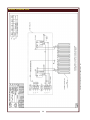
1
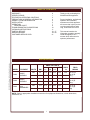
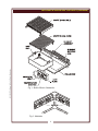
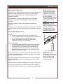
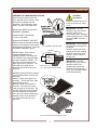
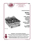
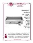
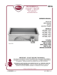
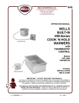
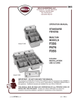
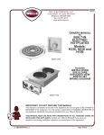
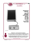
162
WELLS BLOOMFIELD, LLC
10 Sunnen Dr., St. Louis, MO 63143
telephone: 314-678-6314
fax: 314-781-2714
www.wells-mfg.com
OPERATION
MANUAL
for
BUILT-IN
ELECTRIC
CHAR
BROILERS
Model B-406
Models:
B406
B446
B506
Model B-446
includes:
INSTALLATION,
USE and CARE
IMPORTANT: DO NOT DISCARD THIS MANUAL
This manual is considered to be part of the appliance and is to be given to the OWNER or
MANAGER of the restaurant, or to the person responsible for TRAINING OPERATORS of
this appliance. Additional manuals are available from your WELLS DEALER.
THIS MANUAL MUST BE READ AND UNDERSTOOD BY ALL PERSONS USING OR
INSTALLING THIS APPLIANCE. Contact your WELLS DEALER if you have any
questions concerning installation, operation or maintenance of this equipment.
p/n 2M-303673 Rev. F
M162
090416
rms
LIMITED WARRANTY STATEMENT
Unless otherwise specified, all commercial cooking
equipment manufactured by WELLS BLOOMFIELD, LLC is
warranted against defects in materials and workmanship for
a period of one year from the date of original installation or
18 months from the date of shipment from our factory,
whichever comes first, and is for the benefit of the original
purchaser only.
THIS WARRANTY IS THE COMPLETE AND ONLY
WARRANTY, EXPRESSED OR IMPLIED IN LAW OR IN
FACT, INCLUDING BUT NOT LIMITED TO, WARRANTIES
OF MERCHANTABILITY OR FITNESS FOR ANY
PARTICULAR PURPOSE, AND/OR FOR DIRECT,
INDIRECT OR CONSEQUENTIAL DAMAGES IN
CONNECTION WITH WELLS BLOOMFIELD PRODUCTS.
This warranty is void if it is determined that, upon inspection
by an authorized service agency, the equipment has been
modified, misused, misapplied, improperly installed, or
damaged in transit or by fire, flood or act of God. It also
does not apply if the serial nameplate has been removed, or
if service is performed by unauthorized personnel. The
prices charged by Wells Bloomfield for its products are
based upon the limitations in this warranty. Seller’s
obligation under this warranty is limited to the repair of
defects without charge by a Wells Bloomfield factory
authorized service agency or one of its sub-service
agencies. This service will be provided on customer’s
premises for non-portable models. Portable models (a
device with a cord and plug) must be taken or shipped to
the closest authorized service agency, transportation
charges prepaid, for service. In addition to restrictions
contained in this warranty, specific limitations are shown in
the Service Policy and Procedure Guide. Wells Bloomfield
authorized service agencies are located in principal cities.
This warranty is valid in the United States and Canada and
void elsewhere. Please consult your classified telephone
directory, your foodservice equipment dealer or contact:
Service Department, Wells Bloomfield, LLC
10 Sunnen Drive, St. Louis, Missouri 63143
phone (314) 678-6314 or fax (314) 781-2714
for information and other details concerning warranty.
SERVICE POLICY AND PROCEDURE GUIDE and ADDITIONAL WARRANTY EXCLUSIONS
1.
2.
3.
5.
6.
cleaning schedules, are customer responsibility. Those
miscellaneous adjustments noted are customer
responsibility. Proper attention to preventative
maintenance and scheduled maintenance procedures
will prolong the life of the appliance.
7. Travel mileage is limited to sixty (60) miles from an
Authorized Service Agency or one of its sub-service
agencies.
8. All labor shall be performed during regular working
hours. Overtime premium will be charged to the buyer.
9. All genuine Wells replacement parts are warranted for
ninety (90) days from date of purchase on nonwarranty equipment. This parts warranty is limited only
to replacement of the defective part(s). Any use of
non-genuine Wells parts completely voids any
warranty.
10. Installation, labor, and job check-outs are not
considered warranty and are thus not covered by this
warranty.
11. Charges incurred by delays, waiting time or operating
restrictions that hinder the service technician’s ability to
perform service are not covered by warranty. This
includes institutional and correctional facilities.
SHIPPING DAMAGE CLAIM PROCEDURE
NOTE: For your protection, please note that equipment in
this shipment was carefully inspected and packaged by
skilled personnel before leaving the factory. Upon
acceptance of this shipment, the transportation company
assumes full responsibility for its safe delivery.
IF SHIPMENT ARRIVES DAMAGED:
1. VISIBLE LOSS OR DAMAGE: Be certain that any
visible loss or damage is noted on the freight bill or
express receipt, and that the note of loss or damage is
signed by the delivery person.
2. FILE CLAIM FOR DAMAGE IMMEDIATELY:
Regardless of the extent of the damage.
3.
CONCEALED LOSS OR DAMAGE: if damage is
unnoticed until the merchandise is unpacked, notify the
transportation company or carrier immediately, and file
“CONCEALED DAMAGE” claim with them. This
should be done within fifteen (15) days from the date
the delivery was made to you. Be sure to retain the
container for inspection.
Wells Bloomfield cannot assume liability for damage or loss
incurred in transit. We will, however, at your request, supply
you with the necessary documents to support your claim.
xi
162 303673 OpManual for Built-In Electric Charbroilers
4.
Resetting of safety thermostats, circuit breakers, over
load protectors, and/or fuse replacements are not
covered by this warranty unless warranted conditions
are the cause.
All problems due to operation at voltages or phase
other than specified on equipment nameplates are
not covered by this warranty.
Conversion to correct voltage and/or phase must be
the customer’s responsibility.
All problems due to electrical connections not made
in accordance with electrical code requirements
and wiring diagrams supplied with the equipment are
not covered by this warranty.
Replacement of items subject to normal wear, to
include such items as knobs, light bulbs; and, normal
maintenance functions including adjustments of
thermostats, adjustment of micro switches and
replacement of fuses and indicating lights are not
covered by warranty.
Damage to electrical cords and/or plug due to exposure
to excessive heat are not covered by this warranty.
Full use, care, and maintenance instructions supplied
with each machine. Noted maintenance and
preventative maintenance items, such as servicing and
TABLE OF CONTENTS
WARRANTY
SPECIFICATIONS
FEATURES & OPERATING CONTROLS
PRECAUTIONS & GENERAL INFORMATION
AGENCY LISTING INFORMATION
INSTALLATION
OPERATION
BROILER CHART
TROUBLESHOOTING SUGGESTIONS
CLEANING INSTRUCTIONS
PARTS & SERVICE
WIRING DIAGRAM
CUSTOMER SERVICE DATA
xi
1
2
4
4
5
7
9
10
11
12—17
18—20
21
Thank you for purchasing this
Wells Bloomfield appliance.
Proper installation, professional
operation and consistent
maintenance of this appliance
will ensure that it gives you the
very best performance and a
long, economical service life.
This manual contains the
information needed to properly
install this appliance in a
manner which will ensure its
optimum performance.
162 303673 OpManual for Built-In Electric Charbroilers
SPECIFICATIONS
AMPS PER LEG 3ø
MODEL
ELEMENT
B406
SINGLE
ASSEMBLY
B446
SINGLE
ASSEMBLY
B506
DUAL
ASSEMBLIES
VOLTS
KW
L1
L2
L3
NEUT
.
AMPS
1ø
208
5.5
12.9
12.9
22.4
N/A
26.0
240
5.5
11.2
11.2
19.4
N/A
22.5
208
5.5
11.5
22.4
14.4
N/A
26.0
240
5.5
10.0
19.5
12.5
N/A
22.5
208
11.0
30.0
30.0
30.0
N/A
-
240
11.0
26.0
26.0
26.0
N/A
45.0
FIELD
WIRING
3ø 10 ga.
1ø 8 ga.
90 g
3ø 10 ga.
1ø 8 ga.
90 g
3ø 8 ga.
1ø 4 ga.
90g
NOTE: Refer to appropriate Installation Instructions for equipment dimensions, cut-out dimensions,
clearances, etc.
1
FEATURES & OPERATING CONTROLS
ITEM
COMMENT
TEMPERATURE CONTROL
The char-broiler is INFINITE SWITCH CONTROLLED. Power is
applied to the heating elements based on the control knob position and
the amount of energy used.
INDICATOR LIGHT
Light will glow when the infinite switch is in any position other that OFF.
HEATING ELEMENT
ASSEMBLY
The char-broiler element assembly may be raised for cleaning, or to
add water to the drip pan. It is held the “up” position by a support rod
which automatically engages as the element is raised.
ELEMENT GUARD / GRATE
The grate is designed to protect the individual elements from food
contact and spatula abrasion, resulting in prolonged element life and
reduced carbonization. The grate is easily removed for cleaning.
IMPORTANT: Always remove the grate before lifting the element
assembly.
ELEMENT SUPPORT ROD
Hold element assembly in up position. Engages automatically when the
element assembly is raised.
IMPORTANT: Remember to dis-engage the support rod before
lowering element assembly
The heavy-duty removable drip pan is located under the element
DRIP PAN
assembly. The drip pan catches food particles and grease drippings
during broiler operation. Maintain 2 inches of water in the drip pan at all
times during operation of the broiler. The drip pan is easily removed for
cleaning.
DATA PLATE
WELLSLOKS
Gives manufacturer, make, model and serial number. Also voltage and
phase information, and agency approvals.
The broiler is equipped with WELLSLOKS, uniquely designed turnout
tabs, which help secure the broiler to the countertop. (See Installation
Instructions supplied with the particular appliance for details.)
2
162 303673 OpManual for Built-In Electric Charbroilers
IMPORTANT: DO NOT pour water over elements to refill drip pan.
162 303673 OpManual for Built-In Electric Charbroilers
FEATURES & OPERATING CONTROLS (continued)
Fig. 1 Built-In Electric Charbroiler
Fig. 2 Wellsloks
3
PRECAUTIONS AND GENERAL INFORMATION
WARNING:
Electric Shock
Hazard
All servicing requiring access
to non-insulated electrical
components must be
performed by a factory
authorized technician.
DO NOT open any access
panel which require the use of
tools. Failure to follow this
warning can result in severe
electrical shock.
CAUTION:
Risk of Damage
DO NOT connect or energize
this appliance until all
installation instructions are
read and followed. Damage
to the appliance will result if
these instructions are not
followed.
Broilers are intended for use to cook food products for human
consumption. No other use is recommended or authorized by the
manufacturer or its agents.
Broilers are intended for use in commercial establishments, where all
users are familiar with the appliance limitations, use and associated
hazards. Operating instruction and warnings must be read and
understood by all operators and users.
Do not submerge broilers in water. Do not splash, or pour water onto
controls, control panels or wiring.
Disconnect the broiler from electrical power before performing any
service or maintenance.
Allow drip pan to cool before removing from broiler. Do not operate
broiler without the drip pan installed. Do not operate the broiler without
2” of water in the drip pan.
Any parts replacement, maintenance procedure or servicing procedure
requiring the use of tools must be performed by an Authorized Service
Agency.
Any troubleshooting guides, component view, parts lists or installation
guides provided with this equipment are intended for the use of the
qualified technical personnel only.
This manual should be considered a permanent part of this appliance.
This manual and all supplied instructions, diagrams, schematics, parts
break downs, notices and labels must remain with the appliance if it
sold or moved to another location.
AGENCY LISTING INFORMATION
This appliance conforms to NSF Standard 4 for sanitation only if
STD 4
installed in accordance with the supplied Installation Instructions.
This appliance is Underwriters Laboratory recognized (
). Since
this appliance is only a single component of a complete installation, the
E6070
finished installation of this unit
requires additional evaluations to
Underwriters Laboratory standards.
Refer to Installation Instructions included with the broiler for
Underwriters Laboratories conditions of acceptability, electrical
4
162 303673 OpManual for Built-In Electric Charbroilers
Except where otherwise noted, this piece of equipment is made in the
USA and has American sizes on hardware.
INSTALLATION
UNPACKING & INSPECTION
Carefully remove the appliance from the carton. Remove all protective
plastic film, packing materials and accessories from the appliance
before connecting electrical power or otherwise performing any
installation procedure.
Carefully read all instructions in this manual and the Installation
Instruction Sheet packed with the appliance before starting any
installation.
Read and understand all labels and diagrams attached to the
appliance.
Carefully account for all components and accessories before discarding
packing materials. Store all accessories in a convenient place for later
use.
NOTE: DO NOT discard
the carton or other packing
materials until you have
inspected the appliance for
hidden damage and tested it
for proper operation.
Refer to SHIPPING DAMAGE
CLAIM PROCEDURE on the
inside front cover of this
manual.
IMPORTANT: This is a
GENERAL GUIDE. For
specific equipment and cutout
dimensions, and other
installation details, refer to
the Installation Instructions
supplied with the broilers.
CUT-OUT AND INSTALLATION
162 303673 OpManual for Built-In Electric Charbroilers
Cutouts
a. Broilers may be installed in METAL COUNTERS ONLY.
b. Cutout dimensions for broilers and control panels are listed on
the Installation Instructions provided with the broiler.
c. Refer to the Installation Instructions for Underwriters
Laboratories Conditions of Acceptability.
Mounting the broiler:
a. Verify that provided sealants are applied to the under side of
the broiler top flange prior to setting the unit into the cutout.
b. After installation, verify that the tabs on the Wellsloks are
turned out to lock the broiler into the counter (see Fig. 3).
c. Apply a thin bead of food-grade silicone sealant around the
flange to seal it to the counter.
Refer to the Installation Instructions for required clearances. Maintain
required clearances between the appliance and adjacent combustible
and non-combustible surfaces.
Sufficient overhead clearance must be provided to allow the element
assembly to be raised. Refer to the Installation Instruction Sheet for
required clearances.
Install drip pan and element guard/grate prior to heating or using broiler.
Avoid storing flammable or combustible materials near the appliance.
This includes gasoline and other fuels, mops, rags and wrapping paper.
5
Fig. 3 Set the Wellslloks
IMPORTANT: Water
damage caused by failure to
set Wellsloks, failure to install
gasket, or failure to seal
flange to counter is NOT
covered by warranty.
INSTALLATION (continued)
WARNING:
Risk of personal
injury
Installation procedures must
be performed by a qualified
technician with full knowledge
of all applicable electrical
codes. Failure can result in
personal injury and property
damage.
CAUTION:
Electrical Shock
Hazard
The broiler must be
electrically grounded.
Connect the terminal marked
“GND” or “ ” to a suitable
building ground.
ELECTRCAL HOOK-UP
Refer to the nameplate. Verify the electrical service power. Voltage
and phase must match the nameplate specifications. Connecting the
griddle to the wrong voltage can severely damage the unit or cause
noticeable decreased performance.
Use copper wire suitable for a minimum of 90°C for electrical supply
connections.
Broilers are factory wired three-phase (3ø). For single-phase (1ø)
wiring, refer to the wiring diagram attached to the broiler. Conversion to
1ø must be performed by a licensed electrician.
This broiler is not fused. Protect the circuit with properly sized fuses or
circuit breaker.
An electrical disconnect must be installed readily accessible to the
operator of the broiler.
162 303673 OpManual for Built-In Electric Charbroilers
IMPORTANT: Contact a
licensed electrician to install
and connect electrical power
the broiler.
Electrical installation must be
performed by a licensed
electrician in compliance with
all local ordinances and code
requirements.
IMPORTANT: Damage due
to being connected to the
wrong voltage or phase is
NOT covered by warranty.
6
OPERATION
CAUTION:
Hot Surface
PREPARE THE CHAR-BROILER FOR USE
When using the broiler for the first
time, wipe the entire unit with a clean
damp cloth or sponge and mild
detergent. Rinse thoroughly clean
water. Dry with a soft clean cloth.
Exposed surfaces can be hot
to the touch and may cause
burns.
IMPORTANT: DO NOT
attempt to raise the element
assembly without first
removing the grate. Damage
to the hinges will result. Such
damage is NOT covered by
warranty.
Remove the GRATE and raise the
ELEMENT ASSEMBLY.
Install the DRIP PAN and add
2” (5cm) of tap water.
162 303673 OpManual for Built-In Electric Charbroilers
Release the ELEMENT SUPPORT
ROD by lifting the element assembly
slightly, then pulling the lower portion
of the support rod forward. Lower the
ELEMENT ASSEMBLY gently.
MODEL B-406: Grate must be
installed ABOVE elements.
Install the GRATE, front edge first.
The TANGS of the grate go DOWN
and point toward the FRONT. The
grooves on the underside of the
grate align with the elements. The
rear edge of the grate can be
lowered until it rests firmly on the
elements.
Fig. 4 ELEMENT SUPPORT ROD
ELEMENT
HANDLE
FRONT
GRATE TANG
Fig. 5 B-40 GRATE INSTALLATION
MODELS B-446 and B-506: Grate(s)
can be installed above or below the
elements.
ABOVE: Gently lower grate over
elements. The end with flush tabs
goes toward the front.
BELOW: Install one wing bolt in
each tab. The notch in the wing
rests on the lip of the drip pan. The
end with flush tabs must go toward
the front Adjust the wing bolts so
that , when the element assembly is
lowered, the top of the element is
1/4" (6mm) below the top of the
grate fins.
Fig. 6 B-44 and B-50 GRATE INSTALLATION
7
IMPORTANT: Allow drip pan
to cool before removing from
the broiler.
DO NOT operate the broiler
without the drip pan installed.
DO NOT operate the broiler
without 2” (5cm) of water in
the drip pan.
IMPORTANT: DO NOT
attempt to lower the element
assembly without first
releasing the support rod.
Damage to the hinges will
result. Such damage is NOT
covered by warranty.
OPERATION (continued)
CAUTION:
Hot Surface
Exposed surfaces
can be hot to the touch and
may cause burns.
TEMPERATURE CONTROLS
Each section of the broiler is equipped with an individual temperature
control. The desired temperature is controlled by rotating the
TEMPERATURE CONTROL KNOB. Any time the control is turned
“ON”, the adjacent indicator light will glow. Each section of the broiler
may be set to a different temperature setting.
“OFF” removes power from the element., allowing the element to cool.
Use OFF to turn the broiler off at the end of the cooking day.
“LO” is the lowest temperature settings. Use LO for stand-by operation.
“2” thru “8” are temperature settings. Higher number indicate higher
temperature.
“HI” is a continuous ON setting. Use HI for pre-heating the broiler.
USING THE CHAR-BROILER
Fig. 7 TEMPERATURE CONTROL
After the pre-heat period, turn the TEMPERATURE CONTROL to the
desired setting (refer to the Broiler Chart at right for recommended
settings).
After every order, use the brush provided to brush any remaining food
particles from grate and elements. Keeping the cooking surfaces clean
will help in maintaining food taste.
Visually check the water level in the drip pan during operation. Add
water as required to maintain 2 inches (5cm) water depth in the drip
pan.
8
162 303673 OpManual for Built-In Electric Charbroilers
IMPORTANT: DO NOT
POUR WATER OVER
ELEMENTS TO REFILL
PAN.
DO NOT splash or pour water
onto controls, control panels
or wiring.
Pre-Heat the broiler ten (10) minutes by turning the TEMPERATURE
CONTROL to “HI”.
OPERATION (continued)
BROILER CHART
RECOMMENDED COOKING TIMES AND DIAL SETTINGS
NOTE: The times and dial settings in this chart are suggestions only. Your own
experience with your own menu items will be your best guide to achieving the best food
product.
PRODUCT
Condition
THICKNESS
COOKING
SETTING
BEEF Frozen
1/2”
Rare
8
4-6
“
1/2”
Medium
8
7-9
“
3/4”
Rare
7
7-9
“
3/4”
Medium
7
8 - 10
“
1”
Rare
7
12 - 14
“
1”
Medium
7
14 - 16
“
1-1/4”
Rare
6
23 - 25
“
1-1/4”
Medium
6
25 - 27
3/4”
Rare
HI
4-6
3/4”
Medium
HI
5-7
1”
Rare
HI
7-9
1
Medium
HI
8 - 10
1-1/4”
Rare
HI
12 - 14
1-1/4”
Medium
HI
13 - 15
1-1/2”
Rare
HI
14 - 16
1-1/2”
Medium
HI
18 - 20
162 303673 OpManual for Built-In Electric Charbroilers
BEEF Non-Frozen
9
DIAL
TIME
Minutes Total
TROUBLESHOOTING SUGGESTIONS
SYMPTON
POSSIBLE CAUSE
SUGGESTED REMEDY
Won’t heat- - no indicator
lights
Electric disconnect OFF
Circuit breaker tripped
Check / turn disconnect ON
Check / reset circuit breaker
One or more section
won’t heat—or not hot
enough
Temperature control not set
Set temperature control knob to
desired temperature
240V unit run on 208V
Verify proper voltage
Damaged component or wiring
Contact an Authorize Wells
Service Agency for repairs
Temperature control not set
Set temperature control knob to
desired temperature
208V unit run on 240V
Verify proper voltage
Damaged component or wiring
Contact an Authorized Wells
Service Agency for repairs
Element assy loose, or
difficult to raise or lower
Damaged hinge
(see page 7 for precautions)
Contact an Authorized Wells
Service Agency for repairs
Element assy does not
latch in up position
Damaged support rod assembly
Contact an Authorized Wells
Service Agency for repairs
One or more section too
hot
10
162 303673 OpManual for Built-In Electric Charbroilers
NOTE: There are no user
serviceable components in
this appliance. In all cases of
damage or component
malfunction, contact your
Authorized Wells Service
Agency for repairs.
CLEANING INSTRUCTIONS
CAUTION:
Electric Shock
Hazard
PREPARATION
Turn both temperature control knobs OFF.
Allow broiler to cool completely.
Disconnect broiler from electric power.
Disconnect appliance from
electric power before
cleaning.
FREQUENCY
Daily.
CAUTION:
Burn Hazard
TOOLS
Steel Brush with Scraper
Plastic Scouring pad, Soft-Bristled Fiber Brush
Mild Detergent, Non-Abrasive Cleanser
Clean Soft Cloth / Sponge
Allow appliance to cool
completely before cleaning.
CLEANING
1. Remove the grate from the broiler. Clean grate:
a. Use the supplied steel brush with scraper to remove food
particles and residue from grate surfaces.
b. Grate may be washed in sink or dishwasher.
c. Dry the grate and apply a light coating of cooking oil.
162 303673 OpManual for Built-In Electric Charbroilers
2. Raise the element assembly until it latches. Remove and clean
the drip pan:
a. Stubborn food particles maybe removed with a plastic scouring
pad.
b. Drip pan may be washed in a sink or dishwasher.
3. Clean the element assembly:
a. Use a soft-bristled fiber brush to remove any remaining food
particles from the elements.
b. Clean the element rods with a soft damp cloth or sponge and
mild detergent. Rinse by wiping with a soft cloth moistened
with clean water. Dry with a soft cloth.
4. Clean the control panel with a soft damp cloth or sponge and mild
detergent. Rinse by wiping with a soft damp cloth moistened with
clean water. Dry with a soft cloth.
5. Reassemble broiler:
a. Reinstall drip pan.
b. Unlatch element support rod and carefully lower the element
assembly.
c. Reinstall the grate.
Procedure complete.
11
CAUTION:
Electric Shock
Hazard
Do not submerge appliance
in water.
IMPORTANT:
DO NOT spill or pour water
into controls, control panel or
wiring. Damage to internal
components will occur.
Damage to internal
components from water
damage is NOT covered by
warranty.
EXPLODED VIEW: MODEL B406
1
2
20 19
18
3
4
5
6
7
17
8
9
10
16
15
14
12
13
Model: B406 Built-in Electric Charbroiler
PL162
IL1731 Rev. A 4/15/09
12
162 303673 OpManual for Built-In Electric Charbroilers
11
PARTS LIST: B406
162 303673 OpManual for Built-In Electric Charbroilers
B406 Electric Charbroiler
Fig No
1
2
3
4
5
6
7
8
9
10
11
12
13
14
15
16
17
17
18
19
19
20
20
Part No
WS-21707
H6-32728
WS-57509
2P-32428
2A-32729
H6-35594
2A-32840
WS-50131
2A-32841
2A-32806
H6-32730
E7-49046
2E-34593
2R-30371
WS-50385
P2-34015
WS-500686
2R-300666
WS-57508
WS-52722
WS-52723
WS-50007
WS-50005
Qty
1
1
1
1
1
1
1
1
1
2
1
1
2
2
2
1
1
1
1
1
1
24
24
Description
BROILER GRATE B40 / B406
COVER RR ELEM ASSY B40 / B406
CASTING ASSY ELEM REAR
SPRING SUPPORT ROD
ROD HEAD SUPPORT B40 / B406
PAN GREASE B40
PIVOT BRKT LF SIDE
TERM BLK KIT 3-POLE 85AMP
PIVOT BRKT RT SIDE
COVER PIVOT BRKT TUMBLED
TOP ASSY B406
BOX OUTLET MOD WARM FRY
SW INF 240V B CAM 13/16S
KNOB ASSY WARMERS
LIGHT SIGNAL RED PUSH ON
PANEL FR MOD 200
KIT HANDLE B40 / B406
HANDLE BROILERS DIE CAST
CASTING ASSY ELEM FRONT
ELEM ASSY 208V B40 / B406
ELEM ASSY 240V B40 / B406
ELEM 104V 225W BROILER
ELEM 120V 225W BROILER
13
EXPLODED VIEW: MODEL B446
1
2
22 21
20
3
4
5
6
19
7
8
9
11
12
18
17
13
14
15
16
Model: B446 Built-in Electric Charbroiler
PL162
IL1732 Rev. A 4/16/09
14
162 303673 OpManual for Built-In Electric Charbroilers
10
PARTS LIST: MODEL 446
162 303673 OpManual for Built-In Electric Charbroilers
B446 Electric Charbroiler
Fig No
1
2
3
4
5
6
7
8
9
10
11
11
12
13
14
15
16
17
18
19
19
20
21
21
22
22
Part No
2F-30025
H6-32740
WS-57507
2P-32428
2A-34061
H6-35593
2A-32840
2A-32841
2A-32806
H6-32747
WS-57779
WS-57780
WS-50131
P2-31033
2E-34593
P2-40843
I7-Z12221
2R-30371
WS-50385
WS-500687
2R-300666
WS-57506
WS-52737
WS-52738
WS-50020
WS-50019
Qty
1
1
1
1
1
1
1
1
2
1
1
1
1
1
1
1
1
1
1
1
1
1
1
1
18
18
15
Description
GRATE BROILER
COVER RR ELEM ASSY
CASTING ASSY ELEM REAR
SPRING SUPPORT ROD
ROD HEAD SUPPORT
PAN GREASE B44-50
PIVOT BRKT LF SIDE B40
PIVOT BRKT RT SIDE B40
COVER PIVOT BRKT TUMBLED
TOP ASSY B446
CONTACTOR 3POLE 208V 40A
CONTACTOR 3POLE 240V 40A
TERM BLK KIT 3POLE, 85AMP
BOX CONTROL
SW INF 240V B COM 13/16
BRKT MTG THERMO INFINITE
PANEL FRONT
KNOB ASSY WARMERS
LIGHT SIGNAL RED PUSH ON
KIT HANDLE B44
HANDLE BROILERS DIE CASTE
CASTING ASSY ELEM FRONT
ELEM ASSY 208V BASE
ELEM ASSY 240V BASE
ELEM 104V 300W BROILER
ELEM 115V 300W BROILER
EXPLODED VIEW: MODEL B506
1
22 21
2
20
3
4
5
6
19
7
8
9
10
12
13
18
17
16
14
15
Model: B506 Built-in Electric Charbroiler
PL162
IL1733 Rev. A 4/16/09
16
162 303673 OpManual for Built-In Electric Charbroilers
11
PARTS LIST: MODEL B506
162 303673 OpManual for Built-In Electric Charbroilers
B506 Electric Charbroiler
Fig No
1
2
3
4
5
6
7
8
8
9
9
10
11
12
13
14
15
16
17
18
19
19
20
21
21
22
22
Part No
2F-30025
H6-32740
WS-57507
2P-32428
2A-32741
H6-35593
2A-32840
WS-57779
WS-57780
2A-32841
H6-33245
2E-30412
2A-32841
2A-32806
H6-32759
E7-49046
2E-34593
2R-30371
WS-50385
P2-34015
WS-500687
2R-300666
WS-57506
WS-52737
WS-52738
WS-50020
WS-50019
Qty
2
2
2
2
2
2
1
2
2
1
1
1
1
2
1
1
2
2
2
1
2
2
2
2
2
36
36
Description
GRATE
COVER RR ELEMENT
CASTING ASSY, ELEMENT REAR
SPRING, SUPPORT ROD
ROD, HEAD SUPPORT ASSY
PAN GREASE
PIVOT BRKT LF SIDE
CONTACTOR 3POLE 208V 40A
CONTACTOR 3POLE 240V 40A
PIVOT BRKT RT SIDE
COVER PIVOT DBL TUMBLE DE
TERM BLOCK 75AMP
PIVOT BRKT RT SIDE
COVER PIVOT BRKT TUMBLED
TOP ASSY B506
BOX OUTLET MOD WARM
SW INF 240V B CAM 13/16S
KNOB ASSY WARMERS
LIGHT SIGNAL RED PUSH ON
PANEL FR MOD 200
KIT HANDLE
HANDLE BROILERS
CASTING ASSY ELEM FRNT
ELEM ASSY 208V BASE
ELEM ASSY 240V BASE
ELEM 1404V 300W BROILER
ELEM 115V 300W BROILER
17
WIRING DIAGRAM: B406
162 303673 OpManual for Built-In Electric Charbroilers
18
162 303673 OpManual for Built-In Electric Charbroilers
WIRING DIAGRAM: B446
19
WIRING DIAGRAM: B506
162 303673 OpManual for Built-In Electric Charbroilers
20
PARTS & SERVICE
DESCRIPTION
PART NO.
GREASE PAN, B-446 (1 PER UNIT)
B-506 (2 PER UNIT)
H6-35593
GREASE PAN, B-406
H6-35594
GRATE, B-446 (1 PER UNIT)
B-506 (2 PER UNIT)
2F-30025
GRATE, B-406
WS-21707
BRUSH, BROILER
2P-30013
IMPORTANT: Use only
factory authorized service
parts and replacement
filters.
For factory authorized
service, or to order factory
authorized replacement parts,
contact your Wells authorized
service agency, or call:
Wells Bloomfield, LLC
10 Sunnen Drive
St. Louis, MO 63143
Service Parts Dept.
phone: (314) 678-6314
fax:
(314) 781-2714
162 303673 OpManual for Built-In Electric Charbroilers
Service Parts Department can
supply you with the name and
telephone number of the
WELLS AUTHORIZED
SERVICE AGENCY
nearest you.
CUSTOMER SERVICE DATA
please have this information available if calling for service
RESTAURANT _____________________________ LOCATION _____________
INSTALLATION DATE ________________________ TECHNICIAN ___________
SERVICE COMPANY ________________________________________________
ADDRESS ___________________________ STATE ______ ZIP__________
TELEPHONE NUMBER (_____)_____-_________
EQUIPMENT MODEL NO. _______________
EQUIPMENT SERIAL NO. _______________
VOLTAGE: (check one)
208
240
21
WELLS BLOOMFIELD, LLC
10 Sunnen Dr., St. Louis, MO 63143
telephone: 314-678-6314
fax: 314-781-2714
www.wells-mfg.com