1
INSTALLATION / OPERATION / MAINTENANCE
Applies to:
Model VSUS & VSLUS
120V 60Hz
Gas-Fired, Tubular, Radiant,
Low-Intensity Infrared Heater
OWNERS MANUAL
WARNING: Improper installation, adjustment,
alteration, service or maintenance can cause
property damage, injury or death. Read the installation,
operating and maintenance instructions thoroughly
before installing or servicing this equipment.
Part # 700110
Introduction.
Welcome to the new range of vacuum infra-red
heaters. Local regulations may vary and it is the
installer’s responsibility to ensure that such
regulations are satisfied.
and attention is required to ensure that working
at height regulations are adhered to.
PLEASE READ this document prior to
installation to familiarize yourself with the
components and tools you require at the various
stages of assembly.
All installation, assembly, commissioning and
service procedures must be carried out by
suitably qualified competent persons and
conform with local building codes, or in the
absence of local codes, with the National Fuel
Gas Code ANSI Z223.1/NFPA 54.
All dimensions shown are in inches unless
otherwise stated.
When assembling, installing, commissioning
and servicing is undertaken on radiant tube
heaters specified in these instructions, due care
The manufacturer reserves the right to alter
specifications without prior notice.
Document Index.
3: Start Up Instructions
1: Installation Requirements
3.1 Tools Required
3.2 Start up procedure
1.1 Health & Safety
1.2 Heater Suspension
1.3 Wall Mounting
1.4 Clearance to Combustibles
1.5 Gas Connection & Supply Details
1.6 Electrical Connections
1.7 Ventilation Requirements
1.7.1 Unvented Units
1.7.2 Vertical Venting
1.7.3 Horizontal Venting
1.8 Fresh Air Intake
1.9 Technical Details
4: Servicing Instructions
4.1 Tools Required
4.2 Burner Description
4.3 Burner Removal
4.4 Burner Gas Injector Servicing
4.5 Burner Head and Electrode Servicing
4.6 Combustion Fan Assembly
4.7 Radiant Tube Servicing
4.8 Reflector Servicing
4.9 Sweeping of Vent
4.10 Re-commissioning after Service
2: Assembly Instructions
2.1 Tools Required
2.2 Assembly Notes
2.2.1 Tubes
2.2.2 Turbulators
2.2.3 Brackets
2.2.3.1 U-Tube Heaters
2.2.3.2 Tube Alignment Sections
2.2.3.3 Linear 3” SL Tube Heaters
2.2.3.4 Linear - 4” SL Tube Heaters
2.2.4 Couplers
2.2.5 Reflectors
2.2.6 U-Bend
2.2.7 Bends
2.2.8 End Caps
2.2.9 Burner Assembly
2.2.10 Fan Assembly
2.2.11 Heater Configurations
5: Spare parts
6: Troubleshooting Guide
7: Replacing Parts
7.1 Burner Controller Replacement
7.2 Air Pressure Switch Replacement
7.3 Gas Valve Replacement
8: Optional Extra Kits
9: User and Operating Instructions
9.1 To Start Heater
9.2 To Switch Off Heater
9.3 Servicing
2
1. Installation Requirements.
1.1
Health and Safety
1.2 Heater Suspension
A.
Heaters are intended for heating
non-residential indoor spaces and should
only be installed where flammable gases
or vapors are not generally present.
Heaters may be suspended either
horizontal or at an angle, or may be wall
mounted. See section 1.5 for clearance
dimensions.
The installation must conform with local
building codes or, in the absence of local
codes, with the National Fuel Gas Code,
ANSI Z223.1/NFPA 54 or the Natural
Gas and Propane Installation Code, CSA
B149.1.
The unit shall be electrically grounded in
accordance with National Electric Code
ANSI/NFPA 70 and Canadian Electrical
Code CSA C22.1.
The heater may be installed in aircraft
hangars in accordance with the Standard
for Aircraft Hangars, ANSI/NFPA 409,
and in automotive garages in accordance
with the Standard for Parking Structures,
ANSI/NFPA 88A, or the Standard for
Repair Garages, ANSI/NFPA 88B,, or
the Canadian Natural Gas and Propane
Installation Code, CSA B149.1, and are
so marked.
Ensure that minimum clearances will be
maintained to vehicles parked below the
heater.
The standard heaters are approved for
installations between 0 - 2000ft
(0 - 610m) for the US and 0 - 4500 ft
(1370m) for Canada. Conversion kits are
available on installations above these
heights in the USA.
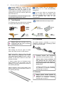
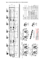
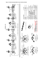
Attachment to the heater support lugs should be
made by a D shackle. The hanging attachments
to overhead steelwork etc. must be purpose
made to good sound engineering practice or of
a proprietary type supplied by others.
They must be adequately fixed and designed to
carry the whole weight of the heater. In the
event of suitable roof steelwork being
unavailable, additional steelwork should be fitted
to enable vertical hangers to be used for
suspending the heaters.
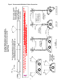
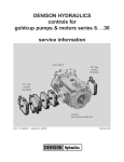
These methods are illustrated in Figure 1. If
there are any doubts as to the strength or
suitability of roof steelwork to which heaters are
suspended, please refer to a Consultant,
Architect, structural engineer, or owner of the
building.
B.
C.
D.
E.
F.
It is recommended that the heater is raised to its
final position once the assembly of the tube/
bracket/reflector has been completed. Longer
tube assemblies may be raised in more than
one sub-assembly with final tube connections
made in the air.
1.3
Wall Mounting
These radiant tube heaters can be wall mounted
using the appropriate bracket.
When using the wall mounting brackets the
heater must be inclined at an angle between 35°
and 55°, when side wall (perimeter) reflectors
are not used.
WARNING:
If not installed, operated and maintained in accordance with the manufacturer’s instructions,
this product could expose you to substances in fuel, or from fuel combustion, which are
known to the state of California to cause cancer, birth defects or other reproductive harm.
3
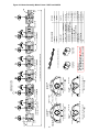
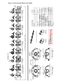
Where chain supports
have an angle of
inclination greater than
15° an equal and
opposite support is
recommended.
4
to be equal
and not more
than 45°.
* These angles
*
*
CHAIN
('U' TYPE SHOWN)
2/0 GA CHAIN
(TWISTED LINK,
PLATED)
EYE HOOKS
REFLECTOR
BRACKET
DROP ROD
TUBE
OPTIONAL
TURNBUCKLE
(±3"ADJUSTMENT)
3/8"Ø ROD
55° SUSPENSION
2/0 GA CHAIN
(TWISTED LINK,
PLATED)
NOTE:
HOOKS ARE TO
BE CLOSED UP
AFTER ASSEMBLY
EYE HOOK
BEAM FASTNERS
CLAMPS
PURLIN
ON U TUBE VARIANTS THE HEATER SHOULD SLOPE DOWNWARDS TOWARDS THE RETURN BEND AND ON
LINEAR VARIANTS SHOULD SLOPE DOWNWARDS TOWARDS BURNER BY APPROX. ½” FOR BOTH
HORIZONTAL AND WALL MOUNTED INSTALLATIONS.
15° max.
Vertical suspension chain ideal. Where
supports are inclined, maximum
recommended angle of inclination is 15°.
It is recommended that on linear variants,
at least the first suspension bracket should
be supported by 2 chains to prevent the
heater tilting.
Figure 1. Recommended Methods of Heater Suspension.
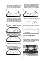
1.4
Clearance to Combustibles.
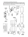
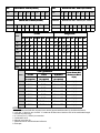
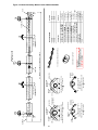
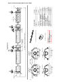
Minimum clearance to combustibles are shown in Figures 2a/2b. Use in conjunction with Table 1 below.
IMPORTANT:
The stated clearance to combustibles represents a surface temperature of 90°F (50°C) above room temperature.
Building material with a low heat tolerance (such as plastics, vinyl siding, canvas, tri-ply, etc.) may be subject to
degradation at lower temperatures.
It is the installer’s responsibility to assure that adjacent materials are not subject to such degradation.
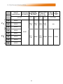
Table 1
Clearance to Combustibles, inches (cm)
A
Model
UT
B1
B
SL
UT
SL
40
63 (160) 49 (125) 25 (64) 48 (122) 41 (105)
60
66 (168) 66 (168) 30 (77) 48 (122) 41 (105)
80
72 (183) 72 (183) 30 (77) 48 (122) 41 (105)
100
72 (183) 72 (183) 32 (82) 48 (122) 41 (105)
125
74 (188) 74 (188) 39 (99) 48 (122) 47 (120)
150
78 (199) 86 (219) 39 (99) 48 (122) 48 (122)
170
200
86 (219) 86 (219) 48 (122) 48 (122) 48 (122)
86 (219) 86 (219) 48 (122) 48 (122) 48 (122)
* unvented
C2
C1
UT
10(26) /
16(41)*
10(26) /
16(41)*
10(26) /
16(41)*
10(26) /
16(41)*
10(26) /
16(41)*
10(26) /
17(44)*
10(26) /
17(44)*
10(26) /
17(44)*
SL
10(26) /
8 (21)
16(41)*
10(26) /
8 (21)
16(41)*
10(26) /
8 (21)
16(41)*
10(26) /
8 (21)
16(41)*
10(26) /
8 (21)
16(41)*
10(26) /
8 (21)
17(44)*
10(26) /
11 (28)
17(44)*
10(26) /
11 (28)
17(44)*
C3
D**
D1
D2
SL
UT
SL
SL
10 (26)
10 (26)
10 (26)
10 (26)
10 (26)
10 (26)
48(122) /
14(36)**
48(122) /
14(36)**
48(122) /
14(36)**
48(122) /
20(51)**
48(122) /
20(51)**
48(122) /
28(72)**
E
18 (46)
20 (51) 10 (26)
18 (46)
20 (51) 10 (26)
18 (46)
20 (51) 10 (26)
18 (46)
20 (51) 10 (26)
18 (46)
20 (51) 10 (26)
18 (46)
28 (72) 10 (26)
48(122) /
10 (26) 40(102)** 18 (46)
28 (72) 10 (26)
48(122) /
10 (26) 40(102)** 18 (46)
28 (72) 10 (26)
** with end caps
WARNING:
Minimum clearance from the heater must be maintained from vehicles parked below heater.
In all situations, clearances to combustibles must be maintained. Signs should be posted in
storage areas to specify maximum stacking height to maintain required clearance to
combustibles. Such signs must either be posted adjacent to the heater thermostats or in the
absence of such thermostats in a conspicuous location. Refer to mounting clearance tables.
5
6
E
C1(*)
C2(*)
Above
Reflector
(unvented)
Burner end.
* unvented
Side unvented
Service
distance
Above
Burner
B1
WARNING!
Ensure
thatthere
there is adequate
NOTE: Ensure
that
adequate provision
provision
in
the
building
for ventilation
in the building for combustion and
combustion and ventilation air supply.
air supply. Installation
Installation
must
meet
minimum
must
meet
minimum
requirements
and appliciable
codes.codes.
requirements
and appliciable
applicable
U Bend end.
D
Side
vented
B
A
Below
heater
Angled view.
Ensure burner is
mounted on
bottom tube
0° to 55°
when angle
mounting
A
End view.
B
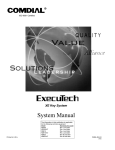
Figure 2a Clearance to Combustibles (U-Tube Variants).
The minimum clearances to combustible materials are given in the tables below. These
minimum distances MUST be adhered to at all times. Adequate clearance MUST be provided
around air openings into the combustion chamber and there MUST be suitable clearance for
accessibility and for combustion / ventilating air supplies.
7
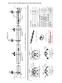
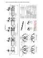
E
C3
Service
distance
Above
Burner
B
Side
vented
Above
Reflector
Burner end.
Optional
90° bend
C2
Below
heater
D2
A
End view.
B
* unvented
Above
outlet
Outlet end.
D1
C1 (*)
end
unvented
B1
Ensure that
there is adequate
WARNING!
provision in the building for
Ensure that there is adequate
combustion
ventilation
air
provision
in the and
building
for
supply. Installation
must
meet
combustion
and ventilation
air supply.
Installation
must
meet
minimum
minimum requirements and
requirements and appliciable
applicable codes.
appliciable codes.
Optional
U bend
D2
Outlet end.
Angled view.
0° to 55°
A
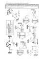
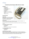
Figure 2b Clearance to Combustibles (Linear Tube Variants).
The minimum clearances to combustible materials are given in the tables below. These
minimum distances MUST be adhered to at all times. Adequate clearance MUST be provided
around air openings into the combustion chamber and there MUST be suitable clearance for
accessibility and for combustion / ventilating air supplies.
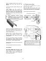
1.5
Figure 3. Correct orientation of Ball Valve
Gas Connection and Supply
WARNING: Before installation, check
that the local distribution conditions,
nature of gas and pressure, and adjustment
of the appliance are compatible.
Gas Flow
The gas connection to the heater is ½” N.P.T
internal thread.
Gas Flow
Injector sizes and manifold pressure for the
burners are shown in Section 1.9. The gas
supply piping and connections must be installed
so that the recommended pressure stated is
achieved.
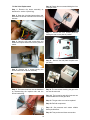
Figure 4. Correct Installation of Flexible
Gas Connection
A gas shut off valve and union should be fitted
in the gas supply line close to the heater and a
⅛” N.P.T plugged tapping, accessible for test
gauge connection, provided immediately
upstream of the appliance gas inlet.
It is essential to provide some flexibility in the
final gas connection by use of an approved
flexible gas connector. See Fig 4.
Take care when making a gas connection
to the heater not to apply excessive turning
force to the internal controls.
Care must be taken to observe the minimum
pipe bend diameter (minimum 10” - 250mm,
maximum 14” - 350mm) & pipe expansion
distance (minimum 1⅛” - 28mm, maximum
3¾”) - 95mm.
The correct installation as shown will allow
for approx 4” of movement due to
expansion.
WARNING: FIRE OR EXPLOSION HAZARD - Expansion of the radiant pipe occurs with
each firing cycle causing the burner to move with respect to the gas line. This can
result in a gas leak producing an unsafe condition. It is therefore essential to provide some
flexibility in the final gas line connection by use of an approved armoured flexible
connector or stainless steel expansion loop as shown in the drawings.
8
Table 3 Gas Supply Pressures
Natural Gas
LP/Propane Gas
Required Gas Pressure (in W.C) 60,000 to 150,000 btu
5.0
11.0
Required Gas Pressure (in W.C) 170,000 to 200,000 btu
7.0
11.0
Max Supply Pressure (in W.C)
14.0
14.0
Gas Type
Connection ½” N.P.T thread
Gas Supply
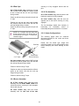
1.6
Electrical Connections
The electrical supply to the heater is by three
wires: live, neutral and ground connections.
Install in accordance with all state & local codes.
WARNING: Before making electrical
connections, switch OFF the main
electrical disconnect. There may be more
than one disconnect switch. Lock out
and tag switch with a suitable warning
label. Electrical shock can cause
personal injury or death.
Where alternative manufacturers controls are
used, please refer to their instructions for siting
and installation details.
This appliance must be electrically grounded
Supply 120V 60Hz single phase.
Standard heater 0.16HP.
Current rating 1.2 amp max (inductive).
Fuse: external 3 amp.
Important: All electrical work should be done by
a qualified electrician in strict accordance with
the National Electrical Code ANSI/NFPA 70 or
Canadian Codes CSA C22.1.
Figure 5.a Typical U-Tube Range Wiring Connections
Switch with
Fuse
Fan plugs
into burner
Figure 5.b Typical Linear Range Wiring Connections
Switch
with Fuse
9
Figure 5c. Single and Multiple Heater Installations 120V Control
G
T
T
BK
120V 60Hz 1 Ph
Supply circuit
110V Thermostat
120V Thermostat
W
BK
GND
L2
L1 (HOT)
W
KEY:
G-GREEN
W-WHITE
BK-BLACK
Burner 1
BK
G
other burners
Figure 5d. Single Heater Installations 24V Control
L1
IND
MV
PS1
PS0
W1
BK
METHOD:Cut and strip pink cables linking terminals W1 and R
Attach thermostat wires using suitable wire nuts.
R
R
Y
C
Y
W1
K
Gas Control
X
R
X
C
COM
TT
R
KEY:
BL - BLUE
BK - BLACK
BR - BROWN
GR - GREY
K - PINK
R - RED
Y - YELLOW
K
BR
24V Thermostat
GR
BL
Figure 5e. Multiple Heater Installations 24V Control
R
40VA
30
Trans
C
W1
C
R
T
T
R
BK
24V Thermostat
S-0700
G
W
G
L2
BK
L1
GND
L2
L1 (HOT)
120V 60Hz 1 Ph
Supply circuit
Relay
Burner 1
Fan center relay
KEY:
G - GREEN
W - WHITE
BK - BLACK
R - RED
W
(Suppled by others)
BK
other burners
If any of the original wire as supplied with the appliance must be replaced, it
must be replaced with wiring material having a temperature rating of at least 220°
10
Figure 5d. Internal burner wiring diagram
G
120V AC Fan
120V/60Hz AC
Supply
KEY:
BL - BLUE
BK - BLACK
BR - BROWN
GR - GREY
G - GREEN
K - PINK
R - RED
W - WHITE
Y - YELLOW
W
G
N
W
R
G
BK
L
BL
120v/24VAC 60Hz
Y
BR
Y
W
BK
G
Pressure Switch
Power ON (red)
BL
BR
GR
R
Transformer
COM
C
X
R
W1
PS0
PS1
MV
IND
L1
R
GR
G
Gas Control
M
C
E
NOTES:Power On light is permanently illuminated when 120V / 60 Hz AC external supply is connected
to burner.
Additional wiring is required to install an optional extra thermostat and / or time clock.
If no thermostat is required then a jumper is fitted between terminals R and W1. In this
configuration the burner will continuously fire until the 120V power supply is disconnected.
Wire specification:- 18 AWG (1.0mm²), Tri-rated, 105°C
11
Gas Valve
BL
GR
BR
K
K
Y
Y
R
R
BK
Burner ON (amber)
degradation by the vent gases.
Vent joints should be sealed and secured
according
to
the
vent
manufacturers
instructions. Should condensation occur the
vent should be shortened or insulated.
1.7 Ventilation Requirements
1.7.1 Unvented units
Heaters may be installed without a vent
providing the governing building codes are met
and consideration is given to possibilities of
condensation on cold surfaces.
Installation
shall
meet
the
requirements when unvented:
The terminal should be at least 3ft (0.91m) away
from any air intake to the building.
If the heater is equipped with ducted combustion
air, the vent terminal must be at least 3ft
(0.91m) away from the air inlet and located
higher than the inlet.
following
Natural or mechanical means shall be provided to supply and exhaust at least 4 CFM
per 1000 BTU per hour input of installed
heaters.
Combustion gases shall not impinge on
combustible materials.
The vent terminal must be installed at a suitable
height above the ground to prevent blockage by
snow.
1.8
Fresh Air Intake
Whenever the heater is installed in locations
where airborne dust or other pollutants are
present, a fresh air supply should be ducted to
the burner.
A fresh air duct of 4” (101mm) dia. should be
installed from the fresh air source to the air
intake connection on the burner housing. A
flexible jointing piece should be installed at the
burner connection (see optional extra kits
Section 8) with hose clamps to facilitate
expansion and contraction.
1.7.2 Vertical venting
The heater can be installed with a vertical vent.
All vent piping should be adequately supported
from the building structure and terminated with
an approved terminal. The maximum
recommended vent length is 25ft (7.6m) with
a maximum of two elbows. All connections
should be properly sealed. Refer fig 6a.
1.7.3 Horizontal venting
The maximum recommended length air duct is
25ft (7.6m) and the maximum number of elbows
is two. The minimum length is 18” (456mm).
Individual units can be vented horizontally
through side walls. Recommended terminals
are Part Numbers V0700 for 4” and V0800 for
6”.
The fresh air duct inlet must be located where it
will receive dust free clean air. An inlet cap with
bird screen must be fitted at the inlet of the duct.
If the duct inlet is located above the roof the
underside of the inlet terminal must be at least
2ft(0.61m) above roof level and at least
10” (254mm) above any projection on the roof
within 7ft (2.1m) of the inlet. Intake pipe Fittings
and sealant are not supplied by the
manufacturer. Refer to Figs. 6c & d.
Distances from adjacent public walkways,
adjacent buildings, opening windows and
building openings, consistent with the National
Fuel Gas Code, ANSI Z223.1/NFPA 54, or the
Natural Gas and Propane Installation Code,
CSA B149.1.
Maximum length of vent is 25ft (7.6m) with two
90° elbows.
Runs of 12ft (3.6m) or shorter can use
4” (101mm) dia vent. Runs over 12ft (3.6m)
should use 6” (152mm) vent pipe.
Any portion of vent that passes through a
combustible wall must be insulated, or use an
approved insulating thimble.
Standard vent terminals must extend at least
6” (152mm) from the wall and at least
24” (609mm) from any combustible overhang.
This protects the building material from
12
Figure 6.a Vertical Venting.
CODE APPROVED VENT
THROUGH ROOF
ROOF
SEAL
SUPPLIED BY OTHERS
ALUMINUM
4" (101mm) O.D. OR
6" (152mm) O.D. FLUE
12'-0" (3.66m)
12'-0" (3.66m)
(APPROXIMATE
MAXIMUM DIMENSIONS)
SEAL JOINTS WITH
HIGH TEMPERATURE SILICONE
END OF RADIANT TUBE
4" (101mm) TO 6" (152mm) DIA. ALUMINUM ADAPTER
REQUIRED ONLY FOR 6" (152mm) DIA. VENT
REFLECTOR
FAN
VENT CAT 1
Figure 6.b Horizontal Venting.
PLAN VIEW
R E F LE C TO R
S E A L JO IN T S W IT H
H IG H TE M P E R A T U R E
S ILIC O N E
S U P P LIE D B Y O T H E R S
6 " (1 52m m )
C O L LA R
4" (101m m ) T O 6" (152m m ) D IA . A LU M IN U M A D A P T E R
R E Q U IR E D O N LY F O R 6" (152m m ) D IA . V E N T S
T E R M IN A L
A LU M IN U M 4" (101m m ) O .D . M A X IM U M LE N G TH = 12 '-0" (3 .66m )
A LU M IN U M 6" (152m m ) O .D .M A X IM U M LE N G TH = 25'-0" (7.62m )
(P LU S A M A X IM U M O F 2 x 90° B E N D S
ALUMINUM 4" (101.6mm) O.D. PIPE
MAX LENGTH = 25'-0" (7.62m) WITH 2-90° LONG RADIUS BENDS
4" (106mm) O.D. FLEXIBLE DUCT
CLAMPS
NOTE: The vent
terminal should be
installed so as to be in
the same atmospheric
pressure zone as the
combustion air inlet of
the appliance
Figure 6.d Wall Terminal Intake Kit.
TERMINAL
36" (914mm) MIN CENTERS
Figure 6.c Fresh Air Ducted Intake.
IN L E T W IT H
B IR D S C R E E N
W A LL
36" (914mm)MIN CENTERS
FAN
SIDE VIEW
WALL
INLET WITH
BIRD SCREEN
SEAL JOINTS WITH
SILICONE OR DUCT TAPE
NOTE: The vent terminal must NOT be
installed below the fresh air intake.
BURNER
6" (152mm)
13
1.9
Technical Details
1
No of Injectors
Gas Connection
½” N.P.T nipple.
Electrical Supply
120 volt 1 phase 60Hz
4” or 6”
Vent size (in)
120 volt 1 phase 60Hz
Unitary Fan Motor Details
1.2A MAX
Current Rating
Electronic Program Start up with Spark Ignition
Ignition
Burner
Size
Natural Gas
Tube Size
Min. Heater
Length
Max. Heater
Length
Min. Heater Max. Heater
Length
Length
BTU/Hr
Inches (mm)
S ft (m)
S ft (m)
U ft (m)
U ft (m)
40
45,720
3 (76)
20 (6.1)
30 (9.1)
20 (6.1)
30 (9.1)
60
60,000
3 (76)
20 (6.1)
40 (12.1)
20 (6.1)
40 (12.1)
80
80,000
3 (76)
25 (7.6)
40 (12.1)
30 (9.1)
40 (12.1)
100
100,000
4 (101)
30 (9.1)
50 (15.2)
34 (10.4)
34 (10.4)
125
125,000
4 (101)
40 (12.1)
60 (18.3)
34 (10.4)
44 (13.4)
150
150,000
4 (101)
40 (12.1)
60 (18.3)
34 (10.4)
44 (13.4)
170
175,000
4 (101)
50 (15.2)
70 (21.3)
44 (13.4)
64 (19.5)
200
200,000
4 (101)
50 (15.2)
80 (24.4)
54 (16.5)
74 (22.6)
Combustion Fan
Details
Pressure
Switch
Burner
Head
Part No.
Part No.
201676
200988
0- 2000 ft (0-610m)
Burner Orifice
Plate
Injector
Part No.
Part No.
40
201063-65
201007-13
60
201063-36
201007-15
80
201063-64
201007-18
100
201063-70
201007-21
FSER38UK
125
201063-26
201007-24
FS100-4H-60DE
150
201063-25
201007-30
Burner
Size
170
201063-24
201631-25
200
201063-71
201631-32
Fan
Type
Support
Spinning
201845
2576T
201841
201841
FS100-4H-66DE
2560-1
FS100-4H-70DE
FS100-4H-96DE
14
USA
Natural Gas 0– 2000 ft (0-610m)
USA
Natural Gas 2001- 4000 ft (611-1220m)
Size
40
60
80
100
125
150
170
200
Size
40
60
80
100 125 150
170
200
“WC
3.4
3.7
3.2
2.7
3.6
3.4
4.4
2.7
“WC
3.2
3.5
3.0
2.6
4.2
2.6
CANADA
Natural Gas 0- 2000 ft (0-610m)
CANADA
3.4
3.2
Natural Gas 2001– 4500 ft (611-1370m)
Size
40
80
100
125
150
170
200
Size
40
60
80
100
125 150
170
200
“WC
3.4 3.7 3.2
2.7
3.6
3.4
4.4
2.7
“WC
3.2
3.5
3.0
2.6
3.4
4.2
2.6
60
U Tube
3.2
Straight Tube
Model
U20 U30 U40 U35 U45 U55 U65 U75 S20 S25 S30 S40 S50 S60 S70 S80
40
●
●
60
●
●
●
●
●
80
●
●
●
●
●
●
●
●
●
●
●
●
●
100
●
125
●
●
●
●
●
150
●
●
●
●
●
●
●
●
●
●
●
●
170
200
●
●
●
●
●
●
Tube Type Material
Linear Heater Min.
Distance to Bend
ft (m)
U-Tube
Linear
All Heaters
Aluminized
(or superior)
Aluminized
(or superior)
Mild Steel
(or superior)
40
TUBE 1
TUBE 1
REMAINDER
10 (3.0)
60
TUBE 1
TUBE 1
REMAINDER
10 (3.0)
80
TUBE 1
TUBE 1
REMAINDER
20 (6.1)
100
TUBE 1
TUBE 1
REMAINDER
20 (6.1)
125
TUBE 1
TUBE 1
REMAINDER
20 (6.1)
150
TUBE 1
TUBE 1
REMAINDER
20 (6.1)
170
TUBE 1
TUBE 1 & 2
REMAINDER
30 (9.1)
200
TUBE 1
TUBE 1 & 2
REMAINDER
30 (9.1)
Model
OPTIONS
1
2
3
4
5
6
7
8
All standard units fitted with unvented vent, natural gas and stainless steel or aluminized reflectors.
1 off 180° ‘U’ bend or up to 2 off 90° ‘L’ bends can be fitted at no less than 50% of the total heater length.
5ft tube kit (linear only).
4” (101mm) or 6” (152mm) vent terminal.
Combustion air kit.
Altitude conversion kit.
Stainless steel or aluminized steel reflectors.
End caps.
15
Table 7a: U-Tube Heater Tube Materials
Model number
BTU/Hr
40U20
3
45,720
60U20
3
60,000
40U30
3
42,720
60U30
3
60,000
80U30
3
80,000
100U35
4
100,000
125U35
4
125,000
150U35
4
150,000
60U40
3
60,000
80U40
3
80,000
125U45
4
125,000
150U45
4
150,000
170U45
4
175,000
170U55
4
175,000
200U55
4
200,000
170U65
4
175,000
200U65
4
200,000
200U75
4
200,000
Tube nomenclature:
CC
AS
MS
4”-3” Combustion tube
Aluminum coated steel
Mild steel
16
Combustion tube
length (ft)
Radiant tube
length (ft)
10 (1-CC)
10 (1-MS)
10 (1-CC)
10 (1-MS)
10 (2#5’-MS)
10 (1-AS)
10 (1-MS)
14 (2#7’-MS)
10 (1-CC)
30 (3#10’-MS)
10 (1-AS)
10 (1-MS)
10 (2#5’-MS)
14 (2#7’-MS)
10 (1-AS)
5 (1-AS)
10 (1-MS)
5 (1#5’-MS)
14 (2#7’-MS)
20 (2#10’-AS)
20 (2#10’-MS)
14 (2#7’-MS)
20 (2#10’-AS)
20 (2#10’-MS)
10 (2#5’-MS)
14 (2#7’-MS)
10 (2#10’-AS)
40 (4#10’-MS)
14 (2#7’-MS)
Table 7b: Linear Heater Tube Materials
Model number
Tube
diameter
BTU/Hr
40S20
3
45,720
60S20
3
60,000
40S25
3
45,720
60S25
3
60,000
80S25
3
80,000
40S30
3
45,720
60S30
3
60,000
80S30
3
80,000
100S30
4
100,000
60S40
3
60,000
80S40
3
80,000
100S40
4
100,000
125S40
4
125,000
150S40
4
150,000
100S50
4
100,000
125S50
4
125,000
150S50
4
150,000
170S50
4
175,000
200S50
4
200,000
125S60
4
125,000
150S60
4
150,000
170S60
4
175,000
200S60
4
200,000
170S70
4
175,000
200S70
4
200,000
200S80
4
200,000
Combustion tube
length (ft)
Radiant tube
length (ft)
Min distance to
bend (ft)
10’ (1-CC)
10’ (1-MS)
10’
10’ (1-CC)
10’ (1-MS)
10’ (2#5’-MS)
10’
20’
10’ (1-CC)
10’
20’
10’ (1-AS)
20’ (2#10’-MS)
10’ (1-CC)
30’ (3#10’-MS)
10’ (1-AS)
30’ (3#10’-MS)
20’
10’ (1-AS)
40’ (4#10’-MS)
20’
20’ (2#10’-AS)
30’ (3#10’-MS)
30’
10’ (1-AS)
50’ (5#10’-MS)
20’
20’ (2#10’-AS)
40’ (4#10’-MS)
30’
20’ (2#10’-AS)
50’ (5#10’-MS)
30’
20’ (2#10’-AS)
60’ (6#10’-MS)
30’
Tube nomenclature:
CC
AS
MS
20’ (2#10’-MS)
4”-3” Combustion tube
Aluminum coated steel tube
Mild steel tube
17
20’
10’
20’
2. Assembly Instructions.
PLEASE READ this section prior
assembly to familiarize yourself with
components and tools you require at
various stages of assembly. Carefully open
packaging and check the contents against
parts and check list.
to
the
the
the
the
Please ensure that all packaging is
disposed of in a safe environmentally
friendly way.
For your own safety we recommend the
use of safety boots and leather faced
gloves when handling sharp or heavy items. The
use of protective eye wear is also
recommended.
The manufacturer reserves the right to alter
specifications without prior notice.
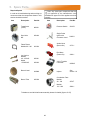
2.1
Tools Required.
Suitable alternative tools may be used.
The following tools and equipment are advisable
to complete the tasks laid out in this manual.
Saw
Horses
Leather
Faced
Gloves
Cordless
Drill
2.2
5/16”
Drive
Phillips
Screwdriver
Wrench
Set
3/16” (5mm)
5/32” (4mm)
Allen wrench
Tape
Measure
Assembly Notes.
2.2.2 Turbulators
Please read these assembly notes in
conjunction with the correct assembly
drawings (figs 10 to 27).
All models include a turbulator or a set of
turbulators. Carefully insert turbulator(s) inside
the tube up to the end tab.
2.2.1 Tubes
Each heating unit has two types of emitter
tubes. See Table 7a and 7b of this manual.
Identify and position tubes on saw horses. All
tubes should be positioned with seams
facing down when installed. Position coupling
fastener so that these cannot be seen from
beneath the heater.
Turbulator lengths and positioning
inside the tube vary between models.
Always ensure correct turbulator is
fully inserted into the correct tube
and from the correct end. Failure to
ensure this practice could cause the
heater to fail.
3” heater versions have a 4” diameter burner
spigot welded at one end. Ensure this tube
assembly is correctly positioned as shown on
the assembly drawings.
Turbulator dimensions and positioning
are indicated on individual assembly
drawings (fig.10 to fig.27).
Where necessary, mark out the position of the
bracket centres from the dimensions shown on
the assembly drawings.
2.2.3 Brackets
Always ensure correct bracket is
used. Bracket type and positioning are
indicated on individual assembly
drawings (fig.10 to fig.27).
18
2.2.3.1 U-Tube Heaters
Type ‘A2’ is a fixed reflector suspension
bracket, tabbed with reflector fixing points.
An extra long ‘floating U bolt’ with ‘stop
nuts’ is located on the firing tube ONLY as
indicated and bolted into position.
Clearance of 1/8” must be provided above
the tube to allow for thermal expansion.
Type ‘A3’ is a fixed reflector suspension
bracket, tabbed with reflector fixing points.
An oversized extra long ‘floating U bolt’
with ‘stop nuts’ is located on the 4” burner
tube ONLY as indicated and bolted into
position.
Clearance of 1/8” must be provided above
the tube to allow for thermal expansion.
This bracket is ALWAYS closest to the
burner.
Type ‘B3’ is a sliding reflector suspension
bracket and NOT fastened to the reflector.
An oversized extra long ‘floating U bolt’ with
‘stop nuts’ is located on the 4” burner tube
ONLY as indicated and bolted into position.
Clearance of 1/8” must be provided above
the tube to allow for thermal expansion.
Type ‘C’ is a reflector support bracket to
retain the reflector (certain UT models).
Slip the brackets onto the tubes in correct order
and fix at correct points as shown on the
relevant assembly drawing.
Ensure fixings are tight to brackets
Note. The first bracket, ‘A3’ on 3” UT
heaters have an oversized ‘U’ bolt on
the burner leg to accommodate the 4”
burner spigot.
Type ‘B’ is a sliding reflector suspension
bracket and NOT fastened to the reflector.
2.2.3.2 Tube alignment sections
(For 170 & 200 U-Tube Angle Mounted
Installations ONLY).
To allow for differential expansion of the tubes,
a tube alignment assembly is fitted to the first
bracket on the fan side radiant tube.
Position U bolt tube alignment sections over the
tube and through bracket prior to clamping.
Type ‘B2’ is a sliding reflector suspension
bracket.
An extra long ‘floating U bolt’ with ‘stop
nuts’ is located on the firing tube ONLY as
indicated and bolted into position.
Clearance of 1/8” must be provided above
the tube to allow for thermal expansion.
19
2.2.3.3 Linear 3” SL Tube Heaters
2.2.3.4 Linear - 4” SL Tube Heaters
Type ‘A1’ is a fixed reflector suspension
bracket, tabbed with reflector fixing points.
An oversized ‘U’ bolt is located on the 4”
burner tube only as indicated and bolted
into position.
This bracket is ALWAYS closest to the
burner.
Type ‘A’ is a fixed reflector suspension
bracket, tabbed with reflector fixing points.
This bracket is ALWAYS closest to the
burner.
Type ‘B’ is a sliding reflector suspension
bracket and NOT fastened to the reflector.
They are fixed at regular intervals down the
length of the tube.
Type ‘B’ is a sliding reflector suspension
bracket and NOT fastened to the reflector.
They are fixed at regular intervals down the
length of the tube.
Type ‘F’ is a fixed reflector support bracket
and are fixed to the reflector via set screws.
Type ‘F’ is a fixed reflector support bracket
and are fixed to the reflector via set screws.
Type ‘S’ is a sliding reflector support
bracket and NOT fastened to the reflector
which allow the reflector to move within.
Type ‘S’ is a sliding reflector support
bracket and NOT fastened to the reflector
which allow the reflector to move within.
Slip the brackets onto the tubes in correct order
and fix at correct points as shown on the
relevant assembly drawing.
Slip the brackets onto the tubes in correct order
and fix at correct points as shown on the
relevant assembly drawing.
Ensure fixings are tight to brackets
Note. The first bracket, ‘A1’ on 3” UT
heaters have an oversized ‘U’ bolt on
the burner leg to accommodate the 4”
burner spigot.
Ensure fixings are tight to brackets
20
2.2.4 Couplers
DRAW
BAND
COUPLING
Draw
Band
Coupling
BOLTS
Bolts
There are two types of 3” and 4” couplers for
joining radiant tubes, bends or optional bend
kits as detailed in Table 8 opposite.
SELF
Self TAPPING
TappingZIP
Zip
SCREWS
Screws
Stainless
STAINLESS
Steel
STEEL
SPACER
Spacer
A high temperature stainless steel coupling.
Table 8. Coupler positions (from burner)
U-Tube 1st coupler 2nd coupler Remainder
40-100
Standard
Standard
Standard
125-200
Hi-temp
Standard
Standard
Linear
Slide the coupler over the tube ensuring that
the rivet stop has butted up to the tube ends.
Using an Allen wrench, tighten the pins.
1st coupler 2nd coupler Remainder
40-100
Standard
Standard
Standard
125-150
Hi-temp
Standard
Standard
170-200
Hi-temp
Hi-temp
Standard
At this point raise the tube assembly into
position and suspend from previously
fixed chains (2/0 min. gauge), or attach to
wall mounting brackets. Wall mounting
brackets must support heater at an angle of
inclination of 45° ± 10°. Longer tube
assemblies may be raised in more than one
sub-assembly with final tube connection
made in the air.
It is recommended that the heater be
suspended to slope slightly - refer to note in
figure 1 for details
Moving between the two set pins, tighten both
ensuring that equal pressure is applied to each
set pin in turn. Complete assembly by drilling
and screwing self tapping retention zip screws.
A standard stainless steel coupling which is
used for all other connections.
2.2.5 Reflectors.
All reflectors must be positioned/
attached to the brackets exactly as
detailed in the assembly drawings.
All reflectors are shipped with a
protective plastic coating which
MUST be removed before use.
Slide the coupler over the tube ensuring that
the tube stop has butted up to the tube ends.
Using a 5/16” drive or flat blade screwdriver,
tighten the bolts.
U-Tube models only. After removing the
protective plastic coating, slip the first reflector
through the brackets until the locating slots align
with the type A bracket fixing points.
* Note: the first suspension bracket may not
necessarily be a fixed type ‘A’ bracket.
Moving between the two band coupling bolts,
tighten both ensuring that equal pressure is
applied to each in turn. Complete assembly by
drilling and screwing self tapping retention zip
screws.
Slide the next reflector backwards through the
brackets and overlap the existing reflector until
the locating slots line up with the type ‘A’
bracket.
DO NOT OVERTIGHTEN!!
Continue along the heater where necessary.
21
Secure overlapped reflectors onto all type ‘A’
brackets using nuts, bolts and flat mud
washers.
2.2.7 Bend(s) (where fitted)
The heater can be installed with 1 or 2 90°
bends, or a 180° U bend.
Slide the bend into the open end of the
coupler ensuring that the screw stop has butted
up to the tube ends. Refer to 2.2.4 for fastening.
All other suspension brackets along the tube
are type ‘B’
Linear models only. After removing the
protective plastic coating, slip the first reflector
through the brackets until the locating slots
align with the first type ‘A’ suspension bracket
fixing point. Secure using nuts, bolts and flat
mud washers.
Typical usage of optional bend kits:
Corner reflector kit (optional)
90°Elbow
Each
subsequent
reflector
must
OVERLAP the previous one as shown
below and to a distance as indicated by
their individual assembly sheets.
overlap
End Caps
Cornerreflectors
reflectorskit(optional)
Corner
(optional)
16” crs
Slide the next reflector backwards through the
brackets and overlap the existing reflector until
the locating slots line up with the type ‘F’
reflector support bracket.
Adjust the type ‘F’ bracket along the tube to
give the correct overlap as shown in the
relevant assembly sheet. Secure U bolt to tube
in this position.
Slide the next reflector through the brackets
and overlap the existing reflector until the
locating slots line up with the previous reflector
slots and type ‘F’ reflector support bracket.
End Caps
U Bend
15”
Bends must be fitted at a distance of at
least 50% of the total heat exchanger e.g.
for a 60ft long heater, the closest to the
burner a bend can be is 30ft.
Secure all three items using nuts, bolts and flat
mud washers.
Continue along the heater where necessary.
2.2.6 U Bend.
For U-Tube models only. Slide the ‘U’ bend
onto the tube ends with the clamping bolts
facing upwards until the predefined stop
position. Tighten clamping bolt arrangement
using socket and wrench.
22
2.2.8 End Caps.
ensuring it is fully engaged. Secure with set
pins.
On U-Tube models only, position the end cap
with no tube holes beneath the reflector profile
at the U bend end with the end cap flanges
facing inwards.
2.2.10 Fan Assembly.
On U-Tube models only, slide fan onto the left
hand tube ensuring it is fully engaged.
Fasten to reflector using cross point set pin and
‘Z’ clips.
On linear models only, slide fan onto the
opposite end to the burner ensuring it is fully
engaged.
Position the end cap with tube holes beneath
the reflector profile at the burner end with the
end cap flanges facing inwards.
Fasten to reflector using cross point set pin and
‘Z’ clips.
The fan discharge should face vertically or
horizontally
for
individually
vented
or
horizontally away from the burner if unvented.
NOTE: on 3” models, the end cap at the
burner end will have one larger hole to
accommodate the larger 4” combustion
chamber spigot.
2.2.11 Heater Configurations.
The following pages show the technical
dimensional details for the u-tube and linear
range of heaters.
set pin
Please note the heater type, length and
reference number from the delivery/advice note
before identifying the correct drawing for that
model.
End Cap
2 x ‘Z’ clips
These holes Burner end only
On linear models only, position ONE end cap
beneath the reflector profile at the fan end with
the end cap flanges facing inwards.
Fasten to reflector using ‘Z’ clips.
Position the other end cap beneath the reflector
profile at the burner end with the end cap
flanges facing inwards.
Fasten to reflector using ‘Z’ clips.
2.2.9 Burner Assembly.
On U-Tube models only, slide the burner
assembly onto the RIGHT HAND TUBE when
viewed from above, ensuring it is fully engaged.
Secure with set pins.
On linear models only, slide the burner
assembly onto the inlet end of the tube
23
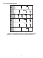
Table 9. Possible Heater Orientations
S30
S40
S50
S60
S70
S80
Bends must be fitted at a distance of at least 50% of the total heat exchanger length from
the burner, e.g. for a 60ft long heater, the closest to the burner a bend can be is 30ft.
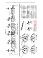
24
25
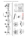
REFLECTOR
U BOLTS
REFLECTOR
FASTNERS
4" BURNER
TUBE
3" + 4" BURNER U BOLT. DETAIL
A3 # 201820
FIRST POINT SUSPENSION BRACKET TYPE A
RADIANT
TUBE
SUSPENSION
BRACKET
REFLECTOR
DETAIL
B # 6576-SUB
SUSPENSION BRACKET TYPE B
U BOLTS
RETURN TUBE FROM FAN END
9'2" (2800mm) TURBULATOR DETAIL
RADIANT
TUBES
7' 7"
TURBULATOR
11'4" NOMINAL OVERALL ASSEMBLED LENGTH
SUSPENSION
BRACKET
7½"
3" x 10' BURNER TUBE
3" x 10' TUBE
10' 0" REFLECTOR TYPICAL OF 1
B
60,000
60-U20
TURBULATOR
1 no 2576T
1 no BR3UTU20
1 no 201823T
BRACKET SET
FAN
or 1 no 3178PMF
or 1 no 201803
END CAP PLAIN STAINLESS STEEL
END CAP HOLE STAINLESS STEEL
1 no 3294PMF
1 no 202196
END CAP HOLE ALUMINUM or
or 1 no 201818
REFLECTOR 10' STAINLESS STEEL
END CAP PLAIN ALUMINUM
1 no T-3103
1 no 202191
REFLECTOR 10' ALUMINUM or
1 no 202163
RADIANT TUBE 10' MILD STEEL
BURNER TUBE 10' ALUNINIZED
PART #
45,720
40-U20
PARTS LIST
BTU/HR
MODEL NUMBER
19¼"
GAP
A3
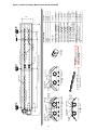
Figure 10. Heater Assembly: Model U tube 40U20 and 60U20.
26
U BOLTS
REFLECTOR
BURNER
TUBE
7½"
REFLECTOR
FASTNERS
U BOLTS
REFLECTOR
B3 # 201821
DETAIL
C # 6575
REFLECTOR SUPPORT BRACKET TYPE C
RADIANT
TUBES
SUSPENSION
BRACKET
3" + 4" BURNER U BOLT. DETAIL
REFLECTOR
DETAIL
B # 6576-SUB
SUSPENSION BRACKET TYPE B
U BOLTS
TURBULATOR DETAIL
4'3" (1300mm) - BURNER TUBE
7'6" (2285mm) - FAN TUBE
RADIANT
TUBES
COUPLERS
6' 3" MAX
IMPORTANT:
THE 2ND REFLECTOR
OVERLAPS THE 1ST.
B
1 no 202163
BURNER TUBE 10' ALUMINIZED
or 2 no 1260
1 no 3294PMF
REFLECTOR 8' ALUMINUM or
REFLECTOR 8' STAINLESS STEEL
END CAP PLAIN ALUMINUM
1 no 6614T
1 no 2576T
TURBULATOR (FAN TUBE)
FAN
1 no BR3UTU30
1 no 6600T
TURBULATOR (BURNER TUBE)
END CAP HOLE STAINLESS STEEL
BRACKET SET
or 1 no 3178PMF
or 1 no 201803
END CAP HOLE ALUMINUM or
END CAP PLAIN STAINLESS STEEL
1 no 202196
2 no T-3154
2 no 202193
RADIANT TUBE 5' MILD STEEL
1 no T-3103
PART #
PARTS LIST
RADIANT TUBE 10' MILD STEEL
80,000
60,000
60-U30
80-U30
45,720
BTU/HR
40-U30
MODEL NUMBER
3" x 5' TUBE
TURBULATORS
3" x 5' TUBE
STANDARD
3" COUPLER
17' 0" NOMINAL OVERALL ASSEMBLED LENGTH
7' 9"
SUSPENSION
BRACKET
3" x 10' BURNER TUBE
3" x 10' TUBE
8' 0" REFLECTOR TYPICAL OF 2
C
19¼"
FIRST POINT SUSPENSION BRACKET TYPE B
RADIANT
TUBE
SUSPENSION
BRACKET
GAP
B3
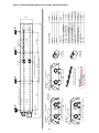
Figure 11. Heater Assembly: Model U tube 40U30, 60U30 and 80U30.
27
REFLECTOR
U BOLTS
REFLECTOR
FASTNERS
4" BURNER
TUBE
REFLECTOR
FASTNERS
U BOLTS
REFLECTOR
A3 # 201820
DETAIL
C # 6575
REFLECTOR SUPPORT BRACKET TYPE C
RADIANT
TUBES
SUSPENSION
BRACKET
3" + 4" BURNER U BOLT. DETAIL
FIRST POINT SUSPENSION BRACKET TYPE A
RADIANT
TUBE
SUSPENSION
BRACKET
7½"
TURBULATOR
COUPLERS
B # 6576-SUB
TURBULATOR DETAIL
4'3" (1300mm) - BURNER TUBE
7'6" (2285mm) - FAN TUBE FROM BOTH ENDS
DETAIL
SUSPENSION BRACKET TYPE B
U BOLTS
REFLECTOR
TURBULATORS
IMPORTANT:
THE 2ND REFLECTOR OVERLAPS
THE 1ST. THE 3RD REFLECTOR
OVERLAPS THE 2ND.
STANDARD
3" COUPLER
7' 7"
3" x 10' TUBE
3" x 10' TUBE
8' 0" REFLECTOR TYPICAL OF 1
21' 8" NOMINAL OVERALL ASSEMBLED LENGTH
SUSPENSION
BRACKET
9' 0"
RADIANT
TUBES
3" x 10' BURNER TUBE
3" x 10' TUBE
10' 0" REFLECTOR TYPICAL OF 1
B
4' 0"
1 no 2576T
FAN
1 no BR3UTU40
BRACKET SET
1 no 6600T
or 1 no 201803
END CAP HOLE STAINLESS STEEL
2 no 6614T
or 1 no 3178PMF
END CAP PLAIN STAINLESS STEEL
TURBULATOR (FAN TUBE)
1 no 202196
END CAP HOLE ALUMINUM or
TURBULATOR (BURNER TUBE)
or 1 no 1349-1
1 no 3294PMF
1 no 202194
END CAP PLAIN ALUMINUM
or 1 no 1260
REFLECTOR 4' ALUMINUM or
REFLECTOR 4' STAINLESS STEEL
1 no 202193
REFLECTOR 8' STAINLESS STEEL
or 1 no 201818
REFLECTOR 10' STAINLESS STEEL
REFLECTOR 8' ALUMINUM or
1 no 202163
3 no T-3103
1 no 202191
BURNER TUBE 10' ALUMINIZED
RADIANT TUBE 10' MILD STEEL
REFLECTOR 10' ALUMINUM or
PART #
PARTS LIST
60,000
BTU/HR
80,000
REFLECTOR
B
80-U40
60-U40
MODEL NUMBER
2' 3" MAX
C
19¼"
GAP
A3
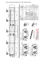
Figure 12. Heater Assembly: Model U tube 60U40 and 80U40
6½"
28
SUSPENSION
REFLECTOR
BRACKET
U BOLTS
B2 # 6580-SUB
SUSPENSION BRACKET TYPE B
4" BURNER U BOLT. DETAIL
RADIANT
TUBES
REFLECTOR
FASTNERS
A2 # 6579-SUB
SUSPENSION BRACKET TYPE A
4" BURNER U BOLT. DETAIL
RADIANT
TUBES
5' 8"
B # 6580-SUB
RETURN TUBE FROM FAN END
8'6" (2600mm) TURBULATOR DETAIL
DETAIL
SUSPENSION BRACKET TYPE B
IMPORTANT:
THE 2ND REFLECTOR OVERLAPS
THE 1ST. THE 3RD REFLECTOR
OVERLAPS THE 2ND.
RADIANT
TUBES
SUSPENSION
REFLECTOR
BRACKET
U BOLTS
**HIGH TEMP
4" COUPLER
STANDARD
4" COUPLER
18' 6" NOMINAL OVERALL ASSEMBLED LENGTH
5' 10"
** HIGH TEMP COUPLER (VSUS125/150 ONLY)
PART #
PARTS LIST
1 no 3293-SUB
REFLECTOR 6' STAINLESS STEEL
END CAP (SET) ALUMINUM or
1 no C112110
1 no 2576T
1 no 2560-1
** HT COUPLER (125 & 150)
FAN (150)
TURBULATOR (FAN TUBE)
FAN (100 & 125)
1 no BR4UTU35
1 no 6619T
BRACKET SET
or 1 no 3182-SUB
or 3 no 1265
REFLECTOR 6' ALUMINUM or
END CAP (SET) STAINLESS STEEL
2 no T-4073
3 no 202195
RADIANT TUBE 7' MILD STEEL
1 no T-4101
150,000
150-U35
1 no T-4103
125,000
125-U35
BURNER TUBE 10' ALUMINIZED
100,000
100-U35
RADIANT TUBE 10' MILD STEEL
BTU/HR
B
MODEL NUMBER
4' 7" MAX
4" x 7' TUBE
TURBULATOR
4" x 10' TUBE
COUPLER
A2
4" x 7' TUBE
SUSPENSION
REFLECTOR
BRACKET
U BOLTS
GAP
26¼"
GAP
B2
4" x 10' TUBE
6' 0" REFLECTORS TYPICAL OF 3
A2
Figure 13. Heater Assembly: Model U tube 100U35, 125U35 and 150U35
5' 9"
B2 # 6580-SUB
SUSPENSION BRACKET TYPE B
4" BURNER U BOLT. DETAIL
RADIANT
TUBES
SUSPENSION
REFLECTOR
BRACKET
U BOLTS
A2 # 6579-SUB
SUSPENSION BRACKET TYPE A
REFLECTOR
FASTNERS
B # 6580-SUB
IMPORTANT:
THE 2ND REFLECTOR OVERLAPS THE
1ST. THE 3RD REFLECTOR OVERLAPS
THE 2ND AND SO ON TOWARDS THE FAN.
RETURN TUBE FROM FAN END
8'6" (2600mm) TURBULATOR DETAIL
DETAIL
SUSPENSION BRACKET TYPE B
SUSPENSION
REFLECTOR
BRACKET
U BOLTS
RADIANT
TUBES
5' 5"
** HIGH TEMP COUPLER (VSUS170 ONLY)
**HIGH TEMP
4" COUPLER
STANDARD
4" COUPLER
24' 0" NOMINAL OVERALL ASSEMBLED LENGTH
5' 8"
** HIGH TEMP COUPLER
1 no T-4101
4 no 202195
or 4 no 1265
1 no 3293-SUB
or 1 no 3182-SUB
1 no BR4UTU45
1 no 6619T
1 no C112110
2 no C112110
1 no 2576T
1 no 2560-1
REFLECTOR 6' ALUMINUM or
BRACKET SET
TURBULATOR (FAN TUBE)
** HT COUPLER (125 & 150)
** HT COUPLER (170 ONLY)
FAN (125)
FAN (150 & 170)
1 no T-4053
2 no T-4053
REFLECTOR 6' STAINLESS STEEL
END CAP (SET) ALUMINUM or
END CAP (SET) STAINLESS STEEL
RADIANT TUBE 5' MILD STEEL (170 ONLY)
RADIANT TUBE 5' MILD STEEL (125/150)
BURNER TUBE 5' ALUMINIZED (170 ONLY) 1 no T-4106
RADIANT TUBE 10' MILD STEEL
2 no T-4103
RADIANT TUBE 7' MILD STEEL
2 no T-4073
BURNER TUBE 10' ALUMINIZED
175,000
170-U45
PART #
125,000
150,000
PARTS LIST
BTU/HR
MODEL NUMBER
125-U45
150-U45
4' 2 MAX"
B
26¼"
GAP
29
4" BURNER U BOLT. DETAIL
RADIANT
TUBES
GAP
SUSPENSION
REFLECTOR
BRACKET
U BOLTS
6½"
4" x 7' TUBE
4" x 5' TUBE
4" x 5' ALUMINIZED TUBE (170 ONLY)
TURBULATOR
4" x 10' BURNER TUBE
A2
4" x 7' TUBE
COUPLER
B2
4" x 5' TUBE
A2
4" x 10' TUBE
6' 0" REFLECTORS TYPICAL OF 4
B2
Figure 14. Heater Assembly: Model U tube 125U45, 150U45 and 170U45
5' 8"
SUSPENSION
REFLECTOR
BRACKET
U BOLTS
B2 # 6580-SUB
SUSPENSION BRACKET TYPE B
4" BURNER U BOLT. DETAIL
RADIANT
TUBES
REFLECTOR
FASTNERS
A2 # 6579-SUB
SUSPENSION BRACKET TYPE A
GAP
30
4" BURNER U BOLT. DETAIL
RADIANT
TUBES
GAP
SUSPENSION
REFLECTOR
BRACKET
U BOLTS
6½"
B # 6580-SUB
IMPORTANT:
THE 2ND REFLECTOR OVERLAPS THE
1ST. THE 3RD REFLECTOR OVERLAPS
THE 2ND AND SO ON TOWARDS THE FAN.
RETURN TUBE FROM FAN END
8'6" (2600mm) TURBULATOR DETAIL
DETAIL
SUSPENSION BRACKET TYPE B
SUSPENSION
REFLECTOR
BRACKET
U BOLTS
RADIANT
TUBES
5' 9"
B2
COUPLER
**HIGH TEMP
4" COUPLER
STANDARD
4" COUPLER
5' 0"
** HIGH TEMP COUPLER
29' 0" NOMINAL OVERALL ASSEMBLED LENGTH
5' 5"
** HIGH TEMP COUPLER
4" x BURNER 10' TUBE
4" x 10' BURNER TUBE
COUPLER
A2
4" x 10' TUBE
B2
4" x 10' TUBE
6' 0" REFLECTORS TYPICAL OF 5
A2
2 no T-4101
2 no T-4103
2 no T-4073
5 no 202195
or 5 no 1265
RADIANT TUBE 7' MILD STEEL
REFLECTOR 6' ALUMINUM or
REFLECTOR 6' STAINLESS STEEL
1 no BR4UTU55
1 no 6619T
2 no C112110
1 no 2560-1
BRACKET SET
TURBULATOR (FAN TUBE)
** HT COUPLER
FAN
1 no 3293-SUB
or 1 no 3182-SUB
END CAP (SET) ALUMINUM or
END CAP (SET) STAINLESS STEEL
RADIANT TUBE 10' MILD STEEL
BURNER TUBE 10' ALUMINIZED
200,000
200-U55
PART #
175,000
170-U55
PARTS LIST
BTU/HR
B
MODEL NUMBER
4' 2" MAX
4" x 7' TUBE
4" x 7' TUBE
TURBULATOR
A2
Figure 15. Heater Assembly: Model U tube 170U55 and 200U55
26¼"
5' 9"
SUSPENSION
REFLECTOR
BRACKET
U BOLTS
B2 # 6580-SUB
SUSPENSION BRACKET TYPE B
4" BURNER U BOLT. DETAIL
RADIANT
TUBES
REFLECTOR
FASTNERS
A2 # 6579-SUB
SUSPENSION BRACKET TYPE A
GAP
31
4" BURNER U BOLT. DETAIL
RADIANT
TUBES
GAP
SUSPENSION
REFLECTOR
BRACKET
U BOLTS
6½"
** HIGH TEMP COUPLER
5' 8"
B # 6580-SUB
IMPORTANT:
THE 2ND REFLECTOR OVERLAPS THE
1ST. THE 3RD REFLECTOR OVERLAPS
THE 2ND AND SO ON TOWARDS THE FAN.
RETURN TUBE FROM FAN END
8'6" (2600mm) TURBULATOR DETAIL
DETAIL
SUSPENSION BRACKET TYPE B
**HIGH TEMP
4" COUPLER
STANDARD
4" COUPLER
34' 0" NOMINAL OVERALL ASSEMBLED LENGTH
5' 2"
SUSPENSION
REFLECTOR
BRACKET
U BOLTS
RADIANT
TUBES
5' 1"
5' 3"
COUPLERS
4" x 5' TUBE
1 no 6619T
2 no C112110
1 no 2560-1
TURBULATOR (FAN TUBE)
** HT COUPLER
FAN
or 1 no 3182-SUB
1 no BR4UTU65
END CAP (SET) STAINLESS STEEL
BRACKET SET
1 no 3293-SUB
or 6 no 1265
REFLECTOR 6' STAINLESS STEEL
END CAP (SET) ALUMINUM or
2 no T-4053
6 no 202195
2 no T-4073
REFLECTOR 6' ALUMINUM or
2 no T-4103
RADIANT TUBE 7' MILD STEEL
RADIANT TUBE 5' MILD STEEL
2 no T-4101
PART #
PARTS LIST
BURNER TUBE 10' ALUMINIZED
200,000
200-U65
RADIANT TUBE 10' MILD STEEL
175,000
170-U65
4' 2" MAX
4" x 7' TUBE
4" x 7' TUBE
B
BTU/HR
A2
MODEL NUMBER
TURBULATOR
4" x 10' BURNER TUBE
B2
4" x 10' BURNER TUBE
** HIGH TEMP COUPLER
A2
4" x 5' TUBE
B2
4" x 10' TUBE
6' 0" REFLECTORS
TYPICAL OF 6
A2
4" x 10' TUBE
B2
Figure 16. Heater Assembly: Model U tube 170U65 and 200U65
26¼"
5' 8"
B2 # 6580-SUB
SUSPENSION BRACKET TYPE B
4" BURNER U BOLT. DETAIL
RADIANT
TUBES
SUSPENSION
REFLECTOR
BRACKET
U BOLTS
A2 # 6579-SUB
REFLECTOR
FASTNERS
5' 9"
5' 2"
** HIGH TEMP COUPLER
4" x 10' TUBE
4" x 10' TUBE
A2
B # 6580-SUB
IMPORTANT:
THE 2ND REFLECTOR OVERLAPS THE
1ST. THE 3RD REFLECTOR OVERLAPS
THE 2ND AND SO ON TOWARDS THE FAN.
RETURN TUBE FROM FAN END
8'6" (2600mm) TURBULATOR DETAIL
DETAIL
SUSPENSION BRACKET TYPE B
5' 2"
**HIGH TEMP
4" COUPLER
STANDARD
4" COUPLER
39' 0" NOMINAL OVERALL ASSEMBLED LENGTH
5' 2"
COUPLER
SUSPENSION
REFLECTOR
BRACKET
U BOLTS
RADIANT
TUBES
** HIGH TEMP COUPLER
SUSPENSION BRACKET TYPE A
GAP
32
4" BURNER U BOLT. DETAIL
RADIANT
TUBES
GAP
SUSPENSION
REFLECTOR
BRACKET
U BOLTS
6½"
4" x 10' BURNER TUBE
B2
4" x 10' BURNER TUBE
A2
4" x 10' TUBE
COUPLER
B2
4" x 10' TUBE
6' 0" REFLECTORS
TYPICAL OF 7
A2
7 no 202195
or 7 no 1265
REFLECTOR 6' ALUMINUM or
REFLECTOR 6' STAINLESS STEEL
1 no BR4UTU75
1 no 6619T
2 no C112110
1 no 2560-1
TURBULATOR (FAN TUBE)
** HT COUPLER
FAN
or 1 no 3182-SUB
BRACKET SET
END CAP (SET) STAINLESS STEEL
1 no 3293-SUB
2 no T-4073
RADIANT TUBE 7' MILD STEEL
END CAP (SET) ALUMINUM or
2 no T-4101
4 no T-4103
BURNER TUBE 10' ALUMINIZED
PART #
200,000
200-U75
PARTS LIST
BTU/HR
4' 2" MAX
4" x 7' TUBE
4" x 7' TUBE
TURBULATOR
B
MODEL NUMBER
5' 0"
COUPLER
A2
RADIANT TUBE 10' MILD STEEL
B2
Figure 17. Heater Assembly: Model U tube 200U75
26¼"
END
CAP
33
SUSPENSION
BRACKET
REFLECTOR
FASTNERS
REFLECTOR
TUBE
STRAP
SUPPLIED
NUT &
BOLT
REFLECTOR
A1 # 201851
DETAIL
F # 200648
FIXED REFLECTOR BRACKET
2 x SCREWS TIGHTEN TO
FIX REFLECTOR
RADIANT
TUBE
4" BURNER U BOLT. DETAIL
SUSPENSION BRACKET TYPE A
U BOLT
RADIANT
TUBES
BURNER
6½"
A1
SUSPENSION
BRACKET
REFLECTOR
B # 6578-SUB
SUPPLIED
NUT &
BOLT
DETAIL
S # 200648
SLIDING REFLECTOR BRACKET
2 x SCREWS TIGHTEN
ONTO BRACKET
DETAIL
COUPLER
IMPORTANT:
THE 2ND REFLECTOR OVERLAPS
THE 1ST. THE 3RD REFLECTOR
OVERLAPS THE 2ND.
STANDARD 3" COUPLER
F
BRACKET SET
TURBULATOR
FAN
END CAP HOLE ALUMINUM or
END CAP PLAIN STAINLESS STEEL
END CAP HOLE STAINLESS STEEL
REFLECTOR 4' ALUMINUM
REFLECTOR 4' STAINLESS STEEL
END CAP PLAIN ALUMINUM
FAN
1 no BR3SLS20
1 no 201823T
1 no 2576T
1 no 202200
or 1 no 3191-1HMF
or 1 no 202197
1 no 202192
or 1 no 202190
1 no 3291
1 no 202163
1 no T-3103
2 no 1280-5
or 2 no 1261-5
BURNER TUBE 10' ALUMINIZED
RADIANT TUBE 10' MILD STEEL
REFLECTOR 8' ALUMINUM or
REFLECTOR 8' STAINLESS STEEL
PART #
END
CAP
PARTS LIST
45,720
60,000
40-S20
BTU/HR
TURBULATOR
B
60-S20
MODEL NUMBER
OVERLAP
4" REFLECTOR
3" x 10' TUBE
9'2" (2800mm) TURBULATOR DETAIL
21' 4" NOMINAL OVERALL ASSEMBLED LENGTH
SUSPENSION BRACKET TYPE B
U BOLT
RADIANT
TUBES
OVERLAP
4" REFLECTOR
3" x 10' BURNER TUBE
S
B
POSITION OF TYPE
'B' BRACKETS ± 2ft
Figure 18. Heater Assembly: Model Linear 40S20 and 60S20.
END
CAP
34
SUSPENSION
BRACKET
REFLECTOR
FASTNERS
REFLECTOR
TUBE
STRAP
SUPPLIED
NUT &
BOLT
REFLECTOR
A1 # 201851
DETAIL
F # 200648
FIXED REFLECTOR BRACKET
2 x SCREWS TIGHTEN TO
FIX REFLECTOR
RADIANT
TUBE
4" BURNER U BOLT. DETAIL
SUSPENSION BRACKET TYPE A
U BOLT
RADIANT
TUBES
BURNER
6½"
A1
REFLECTOR
B # 6578-SUB
SUPPLIED
NUT &
BOLT
DETAIL
S # 200648
SLIDING REFLECTOR BRACKET
2 x SCREWS TIGHTEN
ONTO BRACKET
DETAIL
SUSPENSION BRACKET TYPE B
U BOLT
RADIANT
TUBES
SUSPENSION
BRACKET
OVERLAP
IMPORTANT:
THE 2ND REFLECTOR OVERLAPS
THE 1ST. THE 3RD REFLECTOR
OVERLAPS THE 2ND.
STANDARD 3" COUPLER
11'8" (3560mm) TURBULATOR DETAIL
26' 4" NOMINAL OVERALL ASSEMBLED LENGTH
4" REFLECTOR
OVERLAP
3" x 10' TUBE
4" REFLECTOR
3" x 10' BURNER TUBE
S
B
POSITION OF TYPE
'B' BRACKETS ± 2ft
F
60,000
80,000
60-S25
80-S25
BRACKET SET
TURBULATOR
FAN
END CAP HOLE ALUMINUM or
END CAP PLAIN STAINLESS STEEL
END CAP HOLE STAINLESS STEEL
FAN
1 no BR3SLS20
1 no 200414T
1 no 2576T
1 no 202200
or 1 no 3191-1HMF
or 1 no 202197
1 no T-3154
3 no 1280-5
or 3 no 1261-5
1 no 3291
RADIANT TUBE 5' MILD STEEL
REFLECTOR 8' ALUMINUM or
REFLECTOR 8' STAINLESS STEEL
END CAP PLAIN ALUMINUM
RADIANT TUBE 10' MILD STEEL
1 no 202163
1 no T-3103
END
CAP
BURNER TUBE 10' ALUMINIZED
PART #
45,720
40-S25
PARTS LIST
BTU/HR
MODEL NUMBER
COUPLERS
3" x 5' TUBE
TURBULATOR
B
Figure 19. Heater Assembly: Model Linear 40-S25, 60-S25 and 80-S25.
END
CAP
35
SUSPENSION
BRACKET
REFLECTOR
FASTNERS
REFLECTOR
TUBE
STRAP
SUPPLIED
NUT &
BOLT
REFLECTOR
A1 # 201851
DETAIL
F # 200648
FIXED REFLECTOR BRACKET
2 x SCREWS TIGHTEN TO
FIX REFLECTOR
RADIANT
TUBE
4" BURNER U BOLT. DETAIL
REFLECTOR
B # 6578-SUB
SUPPLIED
NUT &
BOLT
DETAIL
S # 200648
SLIDING REFLECTOR BRACKET
2 x SCREWS TIGHTEN
ONTO BRACKET
DETAIL
SUSPENSION BRACKET TYPE B
U BOLT
SUSPENSION
BRACKET
OVERLAP
F
B
OVERLAP
23" REFLECTOR
3" x 10' TUBE
COUPLERS
IMPORTANT:
THE 2ND REFLECTOR OVERLAPS THE
1ST. THE 3RD REFLECTOR OVERLAPS
THE 2ND AND SO ON TOWARDS THE FAN.
STANDARD 3" COUPLER
11'8" (3560mm) TURBULATOR DETAIL
31' 4" NOMINAL OVERALL ASSEMBLED LENGTH
4" REFLECTOR
3" x 10' TUBE
OVERLAP
RADIANT
TUBES
S
B
4" REFLECTOR
3" x 10' BURNER TUBE
SUSPENSION BRACKET TYPE A
U BOLT
RADIANT
TUBES
BURNER
6½"
A1
POSITION OF TYPE
'B' BRACKETS ± 2ft
S
1 no 202163
2 no T-3103
4 no 1280-5
BURNER TUBE 10' ALUMINIZED
or 4 no 1261-5
1 no 3291
1 no 202200
or 1 no 3191-1HMF
or 1 no 202197
1 no BR3SLS30
1 no 200414T
1 no 2576T
REFLECTOR 8' ALUMINUM or
REFLECTOR 8' STAINLESS STEEL
END CAP PLAIN ALUMINUM
END CAP HOLE ALUMINUM or
END CAP PLAIN STAINLESS STEEL
END CAP HOLE STAINLESS STEEL
BRACKET SET
TURBULATOR
FAN
RADIANT TUBE 10' MILD STEEL
PART #
80,000
4"
FAN
END
CAP
PARTS LIST
80-S30
45,720
60,000
40-S30
BTU/HR
F
60-S30
MODEL NUMBER
TURBULATOR
B
Figure 20. Heater Assembly: Model Linear 40S30, 60S30 and 80S30.
END
CAP
36
REFLECTOR
FASTNERS
REFLECTOR
TUBE
STRAP
SUPPLIED
NUT &
BOLT
REFLECTOR
A1 # 201851
DETAIL
F # 200648
FIXED REFLECTOR BRACKET
2 x SCREWS TIGHTEN TO
FIX REFLECTOR
RADIANT
TUBE
4" BURNER U BOLT. DETAIL
RADIANT
TUBES
REFLECTOR
B # 6578-SUB
SUPPLIED
NUT &
BOLT
DETAIL
S # 200648
SLIDING REFLECTOR BRACKET
2 x SCREWS TIGHTEN
ONTO BRACKET
DETAIL
B
OVERLAP
4" REFLECTOR
COUPLERS
S
IMPORTANT:
THE 2ND REFLECTOR OVERLAPS THE
1ST. THE 3RD REFLECTOR OVERLAPS
THE 2ND AND SO ON TOWARDS THE FAN.
STANDARD 3" COUPLER
B
5 no 1261-5
1 no 3291
1 no 202200
or 1 no 3191-1HMF
or 1 no 202197
1 no BR3SLS40
1 no 200414T
REFLECTOR 8' STAINLESS STEEL
END CAP PLAIN ALUMINUM
END CAP HOLE ALUMINUM or
END CAP PLAIN STAINLESS STEEL
END CAP HOLE STAINLESS STEEL
BRACKET SET
TURBULATOR
FAN
1 no 2576T
1 no 202163
3 no T-3103
or 5 no 1280-5
RADIANT TUBE 10' MILD STEEL
REFLECTOR 8' ALUMINUM or
BURNER TUBE 10' ALUMINIZED
END
CAP
PART #
80,000
B
PARTS LIST
80-S40
60,000
60-S40
3" x 10' TUBE
TURBULATOR
BTU/HR
F
MODEL NUMBER
OVERLAP
4" REFLECTOR
3" x 10' TUBE
11'8" (3560mm) TURBULATOR DETAIL
41' 4" NOMINAL OVERALL ASSEMBLED LENGTH
F
SUSPENSION BRACKET TYPE B
U BOLT
SUSPENSION
BRACKET
OVERLAP
SUSPENSION
BRACKET
4" REFLECTOR
3" x 10' TUBE
OVERLAP
S
B
4" REFLECTOR
3" x 10' BURNER TUBE
SUSPENSION BRACKET TYPE A
U BOLT
RADIANT
TUBES
BURNER
6½"
A1
POSITION OF TYPE
'B' BRACKETS ± 2ft
Figure 21. Heater Assembly: Model Linear 60-S40 and 80-S40.
END
CAP
37
SUSPENSION
BRACKET
6½"
M201345. DETAIL
F
M201345. DETAIL
S
SLIDING REFLECTOR BRACKET
REFLECTOR
FIXED REFLECTOR BRACKET
U BOLT
RADIANT
TUBE
B
SUSPENSION BRACKET TYPE B
M201331-1. DETAIL
OVERLAP
15" REFLECTOR
4" x 10' TUBE
IMPORTANT:
THE 2ND REFLECTOR OVERLAPS
THE 1ST. THE 3RD REFLECTOR
OVERLAPS THE 2ND.
STANDARD 4" COUPLER
F
COUPLERS
8'6" (2600mm) TURBULATOR DETAIL
31' 5" NOMINAL OVERALL ASSEMBLED LENGTH
S
2 x SCREWS TIGHTEN ONTO BRACKET
REFLECTOR
A
U BOLTS
REFLECTORS
RADIANT TUBES
SUSPENSION
BRACKET
4" x 10' BURNER TUBE
B
2 x SCREWS TIGHTEN TO FIX REFLECTOR
U BOLT
RADIANT
TUBE
M201325-1. DETAIL
SUSPENSION BRACKET TYPE A
REFLECTOR
FASTNERS
BURNER
A
POSITION OF TYPE
'B' BRACKETS ± 2ft
B
3 no L201032
or 3 no L201031
or 3 no L201030
2 no L105043
or 2 no L105041
or 2 no L105023
1 no BR4SLS30
1 no 6619T
1 no 2576T
REFLECTOR 10' ALUMASTEEL or
REFLECTOR 10' ALUMINUM or
REFLECTOR 10' STAINLESS STEEL
END CAP ALUMASTEEL or
END CAP ALUMINUM or
END CAP STAINLESS STEEL
BRACKET SET
TURBULATOR
FAN
RADIANT TUBE 10' MILD STEEL
END
CAP
1 no T-4101
2 no T4103
PART #
PARTS LIST
BURNER TUBE 10' ALUMINIZED
100,000
BTU/HR
100-S30
MODEL NUMBER
4" x 10' TUBE
TURBULATOR
B
FAN
Figure 22. Heater Assembly: Model Linear 100S30.
END
CAP
38
SUSPENSION
BRACKET
6½"
M201345. DETAIL
F
M201345. DETAIL
S
SLIDING REFLECTOR BRACKET
REFLECTOR
B
FIXED REFLECTOR BRACKET
U BOLT
RADIANT
TUBE
M201331-1. DETAIL
SUSPENSION BRACKET TYPE B
SUSPENSION
BRACKET
B
COUPLERS
F
4" x 10' TUBE
**HIGH TEMP
4" COUPLER
B
IMPORTANT:
THE 2ND REFLECTOR OVERLAPS THE
1ST. THE 3RD REFLECTOR OVERLAPS
THE 2ND AND SO ON TOWARDS THE FAN.
STANDARD
4" COUPLER
8'6" (2600mm) TURBULATOR DETAIL
41' 5" NOMINAL OVERALL ASSEMBLED LENGTH
OVERLAP
6" REFLECTOR
4" x 10' TUBE
2 x SCREWS TIGHTEN ONTO BRACKET
REFLECTOR
A
U BOLTS
REFLECTORS
RADIANT TUBES
S
2 x SCREWS TIGHTEN TO FIX REFLECTOR
U BOLT
RADIANT
TUBE
M201325-1. DETAIL
B
**HIGH TEMP COUPLER
(VPLUS 125/150 ONLY)
4" x 10' BURNER TUBE
SUSPENSION BRACKET TYPE A
REFLECTOR
FASTNERS
BURNER
A
POSITION OF TYPE
'B' BRACKETS ± 2ft
OVERLAP
12" REFLECTOR
4" x 10' TUBE
TURBULATOR
1 no T-4101
3 no T4103
4 no L201032
or 4 no L201031
or 4 no L201030
2 no L105043
or 2 no L105041
or 2 no L105023
1 no BR4SLS40
1 no 6619T
1 no C112110
1 no 2576T
1 no 2560-1
BURNER TUBE 10' ALUMINIZED
RADIANT TUBE 10' MILD STEEL
REFLECTOR 10' ALUMASTEEL or
REFLECTOR 10' ALUMINUM or
REFLECTOR 10' STAINLESS STEEL
END CAP ALUMASTEEL or
END CAP ALUMINUM or
END CAP STAINLESS STEEL
BRACKET SET
TURBULATOR
** HT COUPLER (125/150 ONLY)
FAN (100 & 125)
FAN (150 ONLY)
END
CAP
PART #
150,000
4"
FAN
PARTS LIST
125,000
150-S40
100,000
BTU/HR
F
125-S40
100-S40
MODEL NUMBER
S
B
Figure 23. Heater Assembly: Model Linear 100S40, 125S40 and 150S40
END
CAP
39
4" x 10' BURNER TUBE
SUSPENSION
BRACKET
F
M201345. DETAIL
S
SLIDING REFLECTOR BRACKET
M201345. DETAIL
FIXED REFLECTOR BRACKET
REFLECTOR
B
2 x SCREWS TIGHTEN ONTO BRACKET
RADIANT
TUBE
M201331-1. DETAIL
4" x 10' TUBE
**HIGH TEMP COUPLER
(VSUS 170 & 200 ONLY)
F
B
S
4" x 10' TUBE
OVERLAP
IMPORTANT:
THE 2ND REFLECTOR OVERLAPS THE
1ST. THE 3RD REFLECTOR OVERLAPS
THE 2ND AND SO ON TOWARDS THE FAN.
**HIGH TEMP
4" COUPLER
8'6" (2600mm) TURBULATOR DETAIL
STANDARD
4" COUPLER
B
12" REFLECTOR
51' 5" NOMINAL OVERALL ASSEMBLED LENGTH
OVERLAP
6" REFLECTOR
4" x 10' TUBE
BURNER TUBE (170-200)
SUSPENSION BRACKET TYPE B
U BOLT
U BOLTS
REFLECTORS
RADIANT TUBES
S
B
2 x SCREWS TIGHTEN TO FIX REFLECTOR
U BOLT
A
REFLECTOR
M201325-1. DETAIL
RADIANT
TUBE
B
**HIGH TEMP COUPLER
(VSUS 125 - 200 ONLY)
SUSPENSION
BRACKET
6½"
SUSPENSION BRACKET TYPE A
REFLECTOR
FASTNERS
BURNER
A
POSITION OF TYPE
'B' BRACKETS ± 2ft
5 no L201032
or 5 no L201031
or 5 no L201030
2 no L105043
or 2 no L105041
or 2 no L105023
1 no BR4SLS50
1 no 6619T
1 no C112110
2 no C112110
1 no 2576T
1 no 2560-1
REFLECTOR 10' ALUMASTEEL or
REFLECTOR 10' ALUMINUM or
REFLECTOR 10' STAINLESS STEEL
END CAP ALUMASTEEL or
END CAP ALUMINUM or
END CAP STAINLESS STEEL
BRACKET SET
TURBULATOR
** HT COUPLER (125 & 150)
** HT COUPLER (170 & 200)
FAN (100 & 125)
FAN (150, 170 & 200)
PART #
1 no
2 no
2 no
150,000
175,000
200,000
150-S50
170-S50
200-S50
PARTS LIST
4 no
4 no
4 no
3 no
3 no
T-4103
1 no
1 no
100,000
125,000
100-S50
125-S50
TUBES
END
CAP
T-4101
4" x 10' TUBE
BTU/HR
TURBULATOR
MODEL NUMBER
F
B
FAN
Figure 24. Heater Assembly: Model Linear 100S50, 125S50, 150S50, 170S50 and 200S50
END
CAP
40
M201345. DETAIL
F
M201345. DETAIL
S
SLIDING REFLECTOR BRACKET
REFLECTOR
B
FIXED REFLECTOR BRACKET
U BOLT
RADIANT
TUBE
M201331-1. DETAIL
S
B
OVERLAP
3¼" REFLECTOR
4" x 10' TUBE
**HIGH TEMP
4" COUPLER
F
IMPORTANT:
THE 2ND REFLECTOR OVERLAPS THE
1ST. THE 3RD REFLECTOR OVERLAPS
THE 2ND AND SO ON TOWARDS THE FAN.
STANDARD
4" COUPLER
8'6" (2600mm) TURBULATOR DETAIL
61' 5" NOMINAL OVERALL ASSEMBLED LENGTH
SUSPENSION BRACKET TYPE B
SUSPENSION
BRACKET
4" x 10' TUBE
B
**HIGH TEMP COUPLER
(VSUS 170 & 200 ONLY)
F
2 x SCREWS TIGHTEN ONTO BRACKET
REFLECTOR
A
U BOLTS
REFLECTORS
RADIANT TUBES
OVERLAP
6" REFLECTOR
4" x 10' TUBE
BURNER TUBE (170-200)
S
B
2 x SCREWS TIGHTEN TO FIX REFLECTOR
U BOLT
RADIANT
TUBE
M201325-1. DETAIL
B
**HIGH TEMP
COUPLER
4" x 10' BURNER TUBE
SUSPENSION
BRACKET
6½"
SUSPENSION BRACKET TYPE A
REFLECTOR
FASTNERS
BURNER
A
POSITION OF TYPE
'B' BRACKETS ± 2ft
S
4 no
4 no
5 no
5 no
T-4103
or 6 no L201031
or 6 no L201030
2 no L105043
or 2 no L105041
or 2 no L105023
1 no BR4SLS60
1 no 6619T
1 no C112110
2 no C112110
1 no 2576T
1 no 2560-1
REFLECTOR 10' ALUMASTEEL or
REFLECTOR 10' ALUMINUM or
REFLECTOR 10' STAINLESS STEEL
END CAP ALUMASTEEL or
END CAP ALUMINUM or
END CAP STAINLESS STEEL
BRACKET SET
TURBULATOR
** HT COUPLER (125 & 150)
** HT COUPLER (170 & 200)
FAN (125 ONLY)
FAN (150, 170 AND 200)
6 no L201032
PART #
2 no
2 no
175,000
200,000
170-S60
200-S60
PARTS LIST
1 no
1 no
4"
FAN
END
CAP
TUBES
F
T-4101
125-S60
150-S60
BTU/HR
OVERLAP
12" REFLECTOR
4" x 10' TUBE
TURBULATOR
B
125,000
150,000
MODEL NUMBER
4" x 10' TUBE
B
Figure 25. Heater Assembly: Model Linear 125S60, 150S60, 170S60 and 200S60
41
SUSPENSION
BRACKET
REFLECTOR
B
M201345. DETAIL
F
M201345. DETAIL
S
SLIDING REFLECTOR BRACKET
U BOLT
RADIANT
TUBE
M201331-1. DETAIL
SUSPENSION BRACKET TYPE B
FIXED REFLECTOR BRACKET
REFLECTOR
A
S
OVERLAP
3¼" REFLECTOR
4" x 10' TUBE
B
F
4" x 10' TUBE
B
**HIGH TEMP
4" COUPLER
IMPORTANT:
THE 2ND REFLECTOR OVERLAPS THE
1ST. THE 3RD REFLECTOR OVERLAPS
THE 2ND AND SO ON TOWARDS THE FAN.
STANDARD
4" COUPLER
8'6" (2600mm) TURBULATOR DETAIL
71' 5" NOMINAL OVERALL ASSEMBLED LENGTH
COUPLERS
4" x 10' TUBE
SUSPENSION
BRACKET
F
B
2 x SCREWS TIGHTEN ONTO BRACKET
RADIANT
TUBE
M201325-1. DETAIL
U BOLTS
REFLECTORS
RADIANT TUBES
OVERLAP
6" REFLECTOR
4" x 10'
BURNER TUBE
B
2 x SCREWS TIGHTEN TO FIX REFLECTOR
U BOLT
S
**HIGH TEMP
COUPLER (FIRST TWO)
4" x 10'
BURNER TUBE
B
SUSPENSION BRACKET TYPE A
REFLECTOR
FASTNERS
END
CAP
BURNER
6½"
A
POSITION OF TYPE
'B' BRACKETS ± 2ft
S
BRACKET SET
TURBULATOR
** HT COUPLER
FAN
END CAP ALUMASTEEL or
END CAP ALUMINUM or
END CAP STAINLESS STEEL
RADIANT TUBE 10' MILD STEEL
REFLECTOR 10' ALUMASTEEL or
REFLECTOR 10' ALUMINUM or
REFLECTOR 10' STAINLESS STEEL
BURNER TUBE 10' ALUMINIZED
PARTS LIST
FAN
END
CAP
12 no BR4SLS70
1 no 6619T
2 no C112110
1 no 2560-1
or 7 no L201030
2 no L105043
or 2 no L105041
or 2 no L105023
5 no T4103
7 no L201032
or 7 no L201031
2 no T-4101
PART #
200,000
175,000
200-S70
170-S70
TURBULATOR
4" x 10' TUBE
BTU/HR
F
B
MODEL NUMBER
OVERLAP
12" REFLECTOR
4" x 10' TUBE
B
Figure 26. Heater Assembly: Model Linear 170S70 and 200S70
42
6½"
S
SUSPENSION
BRACKET
**HIGH TEMP
COUPLER (FIRST TWO)
4" x 10'
BURNER TUBE
B
SUSPENSION
BRACKET
COUPLERS
4" x 10' TUBE
M201345. DETAIL
F
M201345. DETAIL
S
SLIDING REFLECTOR BRACKET
REFLECTOR
B
FIXED REFLECTOR BRACKET
U BOLT
RADIANT
TUBE
M201331-1. DETAIL
F
OVERLAP
3¼" REFLECTOR
4" x 10' TUBE
B
4" x 10' TUBE
B
S
**HIGH TEMP
4" COUPLER
IMPORTANT:
THE 2ND REFLECTOR OVERLAPS THE
1ST. THE 3RD REFLECTOR OVERLAPS
THE 2ND AND SO ON TOWARDS THE FAN.
STANDARD
4" COUPLER
B
F
2 no T-4101
6 no T4103
PART #
F
1 no 6619T
2 no C112110
1 no 2560-1
TURBULATOR
** HT COUPLER
FAN
* OPTIONAL
or 2 no L105041
or 2 no L105023
1 no BR4SLS80
*END CAP ALUMINUM or
*END CAP STAINLESS STEEL
BRACKET SET
4"
FAN
END
CAP
REFLECTOR 10' ALUMASTEEL or
8 no L201032
REFLECTOR 10' ALUMINUM or
or 8 no L201031
REFLECTOR 10' STAINLESS STEEL or 8 no L201030
*END CAP ALUMASTEEL or
2 no L105043
RADIANT TUBE 10' MILD STEEL
BURNER TUBE 10' ALUMINIZED
PARTS LIST
200,000
200-S80
OVERLAP
12" REFLECTOR
4" x 10' TUBE
TURBULATOR
S
B
BTU/HR
4" x 10' TUBE
B
MODEL NUMBER
OVERLAP
3¼" REFLECTOR
4" x 10' TUBE
8'6" (2600mm) TURBULATOR DETAIL
81' 5" NOMINAL OVERALL ASSEMBLED LENGTH
S
SUSPENSION BRACKET TYPE B
F
B
2 x SCREWS TIGHTEN ONTO BRACKET
REFLECTOR
A
U BOLTS
REFLECTORS
RADIANT TUBES
OVERLAP
6" REFLECTOR
4" x 10'
BURNER TUBE
B
2 x SCREWS TIGHTEN TO FIX REFLECTOR
U BOLT
RADIANT
TUBE
M201325-1. DETAIL
SUSPENSION BRACKET TYPE A
REFLECTOR
FASTNERS
END
CAP
BURNER
A
POSITION OF TYPE
'B' BRACKETS ± 2ft
Figure 27. Heater Assembly: Model Linear 200S80
3. Start Up Instructions.
These appliances should be commissioned by a qualified mechanical contractor.
3.1
Tools Required.
The following tools and equipment are advisable
to complete the tasks laid out in this manual.
Leather
Faced
Gloves
Small Flat
Head
Screwdriver
Phillips
Screwdriver
½” Wrench
3.2
Suitable alternative tools may be used.
5/32” (4mm)
Allen
Wrench
Manometer
Large Adjustable
Wrenches for fitting
Of Gas Flex.
Multimeter
illuminate. If the ignition is successful the flame
is detected by the flame sensing probe and the
‘burner on’ lamp will remain on.
Start Up procedure
Inspect installation and ensure that it has been
carried out in accordance with these
instructions. Remove burner and inspect the
electrode assemblies ensuring these are
securely fixed and that all electrical connections
securely made. Re-fit the burner ensuring that it
is correctly positioned and the screws are fully
tightened. Ensure that electrical and gas
supplies are isolated.
If ignition is unsuccessful the gas valve will close
and the spark ignition de-energized after
approximately 15 seconds. For approximately
30 seconds the fan will purge the system then
re-ignition will be attempted. After 2 further failed
attempts at ignition the control unit will ‘lock-out’,
the ‘power on’ lamp will remain illuminated and
the fan will run for 120 seconds and then stop.
To reset after ‘lockout’ switch off the power
supply to the system and wait 2 minutes. Turn
the power on. If repeated ‘lockout’ occurs
investigate the cause.
The gas supply should be purged and tested for
soundness in accordance with local and
National Safety Codes.
Open isolating gas valve and test gas
connections for soundness using soap solution.
Set burner gas pressure as follows:
Switch off the power supply to the heating
system. Connect a ‘U’ tube manometer to the
pressure test point provided on the combination
gas control valve. Remove the cover from the
pressure regulator revealing the adjustable
screw. Start the heater and using a suitable
screwdriver adjust the pressure regulator,
turning the screw clockwise to increase the
pressure or counter-clockwise to decrease the
pressure. Set the pressure to appropriate inches
w.c. from the table of gas pressures for correct
heater description. Switch off the power supply
to the heating system. Disconnect ‘U’ tube
manometer, then securely replace screw in
pressure test nipple.
Open the control housing door by unscrewing
the securing screw. Ensure all internal
components are securely fixed and that all
connections are securely made.
Open the manual gas valve outside the control
housing.
Switch on the electrical supply to start the
heater and observe the correct start up
sequence. Ensure that the settings of any time
switch and thermostat are such that the heating
system will be required to operate.
The fan will start to run and the ‘power on’ lamp
will illuminate. Safe-start checks are carried out
automatically. After the fan has run up to full
speed and a satisfactory pressure condition has
been established, the ignition sequence will
commence. The spark ignition will be energized
producing a spark at the ignition electrode. The
gas solenoid valve will at the same time be
energized and the ‘burner on’ lamp will
Check the operation of the flame safeguard
equipment as follows:
With the heater running normally, switch off the
gas supply at the shut off valve. The heater
should attempt to relight and if the gas valve has
been left off, ‘lock-out’ should occur. This is
indicated by the ‘power on’ lamp being
43
illuminated and fan running, but the ‘burner on’
lamp being off.
Check the operation of the pressure proving
switch as follows:
With the heater running normally, pull off the
silicone rubber tube connecting the vacuum
switch to the combustion chamber. Within 4
seconds the burner should shut off.
Replace the tube securely and observe that the
heater proceeds to ignite in the normal way.
Close the controls door and secure with the
screw.
Commissioning chart
Check installation has
been carried out to these
instructions.
Ensure gas and electricity
supplies are isolated.
Disconnect gas hose from
burner
Remove burner from tube and inspect burner head.
(See servicing instructions)
Replace burner on tube
and secure.
Reconnect gas hose.
Open isolating valve.
Check soundness.
Check thermostat is set to
maximum and is calling
for heat.
Open control housing and
check that all components
are securely fastened.
Switch on electrical supply.
The red neon should now
be illuminated. If restarting
heater a delay of 15sec
should be allowed.
Turn off power and check
that all components are
securely fastened.
The heater should now
run through its start up
sequence and ignite.
NO
A successful ignition is indicated
by the amber light illuminating
and remaining illuminated.
Has the
burner lit?
YES
Check inlet and burner gas
pressure.
Leave the instructions
with a responsible person.
Check operation on flame failure.
Check gas pressure.
Close control housing
44
Check operation of
air pressure switch.
4. Servicing Instructions.
These appliances should be serviced annually by a competent person to ensure safe
and efficient operation. In exceptional dusty or polluted conditions more frequent
servicing may be required. Servicing work should be carried out by a qualified
mechanical contractor.
4.1
Tools Required.
Suitable alternative tools may be used.
The following tools and equipment are advisable
to complete the tasks laid out in this manual.
4.2
Leather
Faced
Gloves
Phillips
Screwdriver
½”
Wrench
5/32”
(4mm)
Allen
Wrench
Large Adjustable
wrenches for fitting
of Gas Flex.
Small Flat
Head
Screwdriver
Multimeter
Manometer
Soft
Brush
Burner Description.
Figure 27. Induced Gas Burner
Cables omitted for
clarity
C
A
B
N
O
P
J
G
H
I
S
A
Ignition Controller
B
Gas Valve
C
Power On Red Lamp
F
Burner Tube
G
Burner Head
H
Injector
I
Igniter Assembly
F
M
45
J
Jet Carrier
M
Gaskets
N
Transformer
O
Burner On Amber Lamp
P
Burner Orifice Plate
S
Flame Plate Location (if fitted)
4.3 Burner Removal
4.4 Burner Gas Injector Servicing
Step 1: Isolate power and gas supplies.
Step 1.a: Remove the burner support casting
and gasket.
Step 2: Unplug the power connectors.
Step 3: Detach the gas supply as shown
below, taking care to support the burner
connection.
Step 1.b: The burner head assembly can be
disconnected by separating the connectors of
the ignition lead assembly and removing the
pressure switch silicon tube.
Step 4: If ducted air is connected, loosen hose
clamp and remove the flexible hose from the
burner.
Step 2: The gas injector can be inspected and
replaced if contaminated or blocked.
Step 5: Loosen the set screw on the burner
support casting to enable the burner to be
removed from the radiant tube.
When replacing the gas injector ensure
approved thread sealant is used.
Step 6: Remove the burner and position
the burner in a safe area to prevent the
burner or components attached to the burner
from falling to the ground.
Step 3: Reconnect ignition leads and silicon
tube to test nipple. Refit gasket and support
casting.
46
Step 5: Refit the electrode assembly and ensure
the connections are secure to prevent incorrect
sparking of the spark electrode.
4.5 Burner Head and Electrode Servicing
Step 1: Check the pepper pot burner head for
contamination. If necessary this can be
removed. See below. This can be cleaned
together with the inside of the burner tube.
Step 6: Check the positions and spark gap as
shown below.
Step 7: The burner assembly is ready to refit
after servicing the combustion fan and the
radiant tube assembly.
4.6 Combustion Fan Assembly
Step 1: Loosen the clamp fitting on the vent.
Step 2: The pepper pot burner head can be
replaced ensuring the 5 holes on the outer ring
are aligned alongside the probes.
Step 3: The condition of the igniter assembly
can be checked for deterioration. However, we
advise replacement at each service to ensure
continued reliability.
Step 2: Loosen the set screw.
Step 4: Detach the electrode assembly from
the burner head by removing the two screws
and separating the igniter lead connectors.
Step 3: The combustion fan can now be
detached.
47
Step 4: Withdraw the turbulators from the
appliance. Carefully note their condition and
position. Replace turbulators if necessary.
Step 4: Remove the fan orifice plate spinning.
Step 5: Inspect the impeller and remove any
dust with a soft brush.
Step 5: The turbulators should be cleaned with
a soft brush.
Step 6: Remove any dust from fan scroll and
from around the motor.
Step 6: If required the interior of the tubes can
then be cleaned using an industrial vacuum
cleaner, or by using long poles and a scraper.
Step 7: Ensure the impeller rotates freely.
Step 8: Refit components.
Step 7: Refit components.
4.7 Radiant Tube Servicing
4.8 Reflector Servicing
Step 1: Brush any dust from the exterior of the
tubes.
The condition of the reflectors should be noted.
If necessary the reflectors can be cleaned with a
mild detergent. This can significantly improve the
efficiency of the appliance.
Step 2: Inspect the fan and burner tubes
visually. If the tubes appear clean, skip to
servicing the reflector.
4.9 Sweeping of Vent
Step 3: Remove the U bend (on U heaters)
Inspect the fresh air inlet duct and vent to ensure
they are free from any blockage or obstruction.
The air inlet terminal and vent terminal should be
inspected to ensure they are not liable to
obstruction.
4.10 Re-commissioning After Service
After servicing of the heater has been
undertaken,
it
will
be
necessary
to
re-commission the heater as detailed in
Section 3 of these instructions.
48
5. Spare Parts.
Required Spares
In order to aid troubleshooting and servicing we
recommend that the components shown in this
section should be stocked.
Item
Description
Part No.
Transformer
(30VA)
900531
Gas Valve
NG
Flame Plates
Models 60 / 100
Note: Any spare part components that are
not approved by the manufacturer could
invalidate the approval of the appliance and the
warranty.
Item
Description
Part No.
Pressure Switch
201676
Single Probe
Ignitor with
Connector Lead
202444
201854
202531
Amber Neon
(Burner On)
2175-1
Red Neon
(Power On)
2180-1
900545
Jet Carriers
Models
40 - 150 NG
Model
170/200 NG
202261
202262
24V UT Ignition
Controller
Burner Head
200988
Injector
Burner Tube
200358
Combustion Fans
Models
40 - 100
2576T
Models
125 - 200
See
section 1.8
2560-1
Turbulators: see individual heater assembly sheets for details (figures 10-27)
49
6. Troubleshooting Guide.
START
Ensure gas & electricity
supplies are enabled.
Turn any external timer
to call for heat (if fitted).
Does the Power On
light illuminate?
NO
Is there power to the
burner?
YES
CHECK: 1. Transformer
2. Integrity of wiring connections.
3. Light.
NO
CHECK: 1. Operation of any timer or control.
2. External fuses.
3. Supply Voltage is 120VAC 60Hz
YES
Set thermostat to call for
heat at maximum setting
Does the fan run?
Is there power to
the fan?
NO
YES
CHECK: 1. Voltage supply to fan terminal 120VAC 60Hz
2. Integrity of wiring connections.
3. Fan.
NO
YES
CHECK: 1. Integrity of wiring connections.
2. Pressure switch operation.
3. Ignition controller.
4. Transformer.
Do the amber
lights illuminate after a
purge period?
NO
Does the Pressure
switch close?
YES
NO
YES
CHECK: 1. Hose connection to Pressure switch.
2. Air inlet, outlet, and emitter tubes for obstructions.
3. Pressure switch operation.
4. Supply voltage 120VAC / 60Hz
5. Transformer.
6. Ignition Controller.
50
CHECK: 1. Pressure switch wiring connections.
4. Integrity of wiring connections.
5. Amber lights.
6. Ignition controller.
5. Transformer
6. Troubleshooting Guide.
To aid the troubleshooting process, the UT controller has a LED flash code diagnostic sequence:
Steady Off
Steady On
1 Flash
2 Flashes
3 Flashes
4 Flashes
5 Flashes
6 Flashes
No control power
Power applied, control OK
Combustion pressure switch open with blower on
Combustion pressure switch closed with blower off
Lockout from the three ignition trials
Lockout from five flame losses
Control hardware fault detected
Lockout from five pressure switch losses
51
7. Replacing Parts.
7.2 Air Pressure Switch Replacement
Turn off gas and any electrical supplies to
the heater before starting repair work.
Step 1: Open left hand door. Disconnect the two
silicone impulse tubes from the pressure switch.
7.1 Burner Controller Replacement
Step 1: Loosen screw in burner lid and open
the right hand burner access door.
Step 2: Disconnect burner controller from the
wiring harness.
Step 2: Remove the two retaining screws as
shown below.
Step 3: Disconnect the HT Lead from burner
controller.
Step 3: Remove electrical connections. The air
pressure switch can now be removed.
Step 4: Remove the two screws attaching the
controller to the burner door and remove.
Step 4: Fit the new air pressure switch ensuring
the impulse tubes and wire connections are
connected as shown below.
Step 5: Fit new burner controller
Step 6: Refit leads
Step 5: Test product and close access doors.
Step 7: Test product and close access door.
52
Step 6: Detach the two screws holding the front
of the gas valve.
7.3 Gas Valve Replacement
Step 1: Remove the burner assembly as
described in section 4 (Servicing).
Step 2: Open the right hand access door and
disconnect the burner controller from the wiring
harness.
Step 7: Remove the four screws (arrowed)
holding the rear burner plate in position.
Step 3: Open the left hand access door and
detach the impulse hoses from the air pressure
switch.
Step 8: Remove the rear plate complete with
gas fitting .
Step 4: Remove the 4 screws holding the
burner head onto the burner assembly.
Step 5: The burner head can now be detached
by disconnecting the impulse tube and the
burner head wiring.
Step 9: The two screws retaining the gas valve
can now be removed.
Step 10: The jet carrier and wiring harness can
now be detached from the gas valve.
Step 11: The gas valve can now be replaced.
Step 12: Refit all components.
Step 13: Set pressures and ensure reliable
burner performance.
Step 14: Test product and close access door.
53
8. Optional Extra Kits.
MODEL
Natural Gas
Altitude
Conversion Kit
Combustion
Air inlet Kit
UT & SL
3”
40
202255
60
202255
80
202255
100
202256
Aluminized
Steel End Cap
Kit (1Pair)
UT
SL
Stainless Steel
90° Elbow
End Cap
Kit (1 Off)
Kit (1 Pair)
180°
U-Bend
Kit
UT
SL
4” SL ONLY
3184-1- 3185-1SUB
SUB
3184SUB
3185SUB
N/A
3182-1202587
SUB
3182SUB
202588
202647
4”
125
202257
150
202258
170
202259
200
202260
54
202631
202632
55
56
9. User & Operating Instructions.
AmbiRad is the manufacturer of a series of tubular infra-red heaters designed for overhead heating
of industrial and commercial buildings. Individual heating units are suspended from the roof or
mounted at an angle on the wall.
1.
This appliance must only be installed by qualified craftsmen in accordance with
the requirements of local and National Codes.
2.
This appliance must be grounded in accordance with the National Electrical
Code ANSI/NFPA No.70.
3.
Never rest anything, especially ladders, against the heaters.
9.1 To Start the Heater
1. First ensure that the gas supply to each
heater is turned on by opening the main
gas shut off valve.
2. Ensure that the setting of any time switch
and thermostat are such that the heating
system will be required to operate.
attempted. After 3 failed re-ignition attempts
the control unit will ‘lock-out’, the ‘power on’
lamp will remain illuminated and the fan will
continue to run. To reset after ‘lockout’,
switch off the power supply to the heater
and wait 5 minutes. Turn the power on. If
repeated ‘lockout’ occurs investigate the
cause.
9.2. To Switch Off the Heater
3. Switch off the electricity supply to the
heater. The fan will start, the ‘power on’
light on the burner will illuminate and
ignition commence.
Switch off electrical supply to the heater.
The burner and the fan will shut off.
9.3. Servicing
4. Ignition will occur.
To ensure continued, efficient and safe
operation it is recommended that the heater
be serviced annually by a qualified person
in normal working conditions, but in
exceptionally dusty or polluted conditions
more frequent servicing may be needed.
Document reference number US/VS/017/0115
5. If ignition is successful the gas valve will
close and the spark ignition de-energize
after approximately 15 seconds. For
approximately 30 seconds the fan will
purge the system then re-ignition will be
Ambi-Rad, P.O. Box 354
Fortville, IN 46040 USA
Telephone 317-577-0337
Facsimile 317-842-3989
Website www.ambirad.com/us
For the Distributor Nearest please call
1-888-330-4878
AmbiRad is a registered trademark of AmbiRad Limited. Because of continuous product
57 AmbiRad reserves the right to change product specification without due notice.
innovation,