1
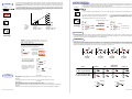
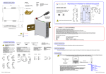
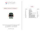
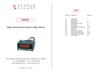
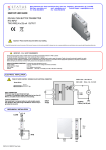
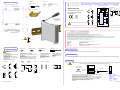
MOUNTING
MECHANICAL INSTALLATION
Enclosure
Screwdriver
1
Style
Material
Terminals
Cable
Colour
Ø 3 mm
11/12
Status Instruments Ltd, Green Lane Business Park, Green Lane, Tewkesbury, Gloucestershire, UK, G L20 8DE
Web Page: www.status.co.uk Tel : +44 (0) 1684 296818 Fax: +44 (0) 1684 293746 email : [email protected]
DIN Rail Mount
Blend PC/ABS self extinguishing
Screw terminal
2.5 mm Max
Grey
SUPPLY (20 to 240) V AC or DC
INPUT
13/14/15/16/17/18
12
SEM1700 USER GUIDE
2
ANALOGUE OUT PUT
Internal Powered
current Output
Temperature
EN60715 DIN RAIL
+
Temperature/Process Conditioner with
Universal input, outputs supply plus
manual config/trim.
7
2
-
Voltage
8
7
7
4
T/C
Load
PT100
1
8
6
10
8
2
10
-
3
4
T RIP OUTPUT
4
V /mV
-
-
9
2
V
Vout
Vs
Load
8
Process
+
+
9
3
+
To fit or release module
Insert screwdriver into
slot and lever latch
away from body
External Powered
(4-20) mA Output
5
2
2
4
Slide Wire
13
c
14
a
15
b
TRIP 2 (B)
5
3
1
+
+
-
Important - Please read this document before any installing.
10/9/8/7
OUTPUT
11
T
x
6
mA
-
16
c
17
a
18
b
USB
3
4
Transmitter
mA Sense
TRIP 1 (A)
SEM1700
6/5/4/3/2/1
Every effort has been taken to ensure the accuracy of this document, however we do not accept responsibility for damage, injury, los s or expense resulting from errors and omissions, and we reserve the right of amendment without notice.
IMPORTANT - CE & SAFETY REQUIREMENTS
All Dimensions in mm
This product is suitable for environment Installation category II pollution degree.
The product is classed as "PERMANENTLY CONNECTED EQUIPMENT".
Product must be DIN rail mounted, inside a suitable enclosure providing environmental protection to IP65 or greater.
Dc supply must be derived from a local supply and not a distribution system.
Max relay contact rating 240 V AC @ 1 A (30 V DC @ 1A). Any circuit connected to a contact must be fused with a 2 A (T) fuse.
To maintain CE EMC requirements , input and supply wires must be less than 30 metres.
The product contains no serviceable parts , or internal adjustments. No attempt must be made to repair this product. Faulty units must be returned to supplier for repair.
This product must be installed by a qualified person. All electrical wiring must be carried out in accordance with the appropriate regulations for the place of installation.
Before attempting any electrical connection work, please ensure all supplies are switched off.
+ 70 °C Max
Ambient Range
ABSOLUTE MAXIMUM CONDITIONS ( To exceed may cause damage to the unit):-
- 20 °C Min
Supply Voltage
Input Voltage
Input Current
Output
Trips
Ambient
External Supply
ELECTRICAL INSTALLATION
Screened Cable
TURN OFF SUPPLY BEFORE
WORKING ON ANY ELECT RICAL
CONNECTION
INPUT CONNECTION
For cable length < 3 Metres no screen or
twisted pair required.
Thermocouple inputs must use correct
compensation cable.
PT100 inputs all three wires must be equal
length (resistance).
Max input cable length 30 metres.
Screwdriver
TC Compensation Cable
Twisted Pair Cable
Ø 3mm
PRODUCT SPECIFICATION
Screened
ANALOGUE OUTPUT CONNECTION
For cable length < 3 metres no screen or twisted
pair required.
Use twisted pair or screened for current output
(3 to 1000 ) metres.
Voltage output use screened cables (3 to 30)
metres, cable lengths > 30 metres not advised.
± 240 V dc ± 240 V ac (Protected for over voltage )
± 24 V between any terminals
± 50 mA between terminals
30 V dc
(240 V ac @ 1 A, 30 V dc @ 1 A) non inductive
Temperature (-30 to 75) °C Humidity (10 to 95) % RH (Non condensing)
1 Amp anti surge fuse recommended
Please refer to the product data sheet for full specification, available to down load at www.status.co.uk.
TRIP OUTPUT CONNECTION
Trip outputs are isolated
from each other.
Max switching current (1 A
@ 240 V ac, 1 A @ 30 V dc)
Non Inductive
SUPPLY CONNECTION
Supply input is not polarity
sensitive.
Max supply 240 V ac or
240 V dc
RECEIVE AND UNPACKING
Please inspect the packaging and instrument thoroughly for any signs of transit damage. If the instrument has been damaged, please notify your supplier immediately.
CONFIGURATION
Temperature
2
+
7
-
4
4
V /mV
T/C
Load
3
PT100
c
c
16
14
a
17
a
15
b
18
b
13
T
x
+
+
9
Vout
Vs
+
11
Device
a.c.
12
d.c.
-
USB_LINK software
(usb_link V2.0 or greater)
-
-
COMPUTER
USB CABLE
10
8
+
+
-
7
3
1
2
TRIP 1(A)
IMPORTANT During configuration the device takes its power from the USB port, therefore no power connection is required. The device can be configured whilst powered
but the computer used must be isolated from the mains supply earth to avoid ground loop effects.
8
Load
Slide Wire
8
5
TRIP 2(B)
2
V
4
Voltage
6
2
+
Current
Externally
Powered
Current
Internal
Powered
Process
Disk or download @
www.status.co.uk
mA
The following parameter can be configured by simply entering as prompted by the software package.
3
4
Transmitter
mA Sense
D2475-01-05 CN4871 SEM1700 User
· Input type / input sensor / units (temperature inputs) / sample rate
· Scale input to process variable (process inputs only)
· Analogue Output / Set Type voltage or current / scale output signal range / scale output to process
Set adjustable damping for both rising and falling output. Set correction for voltage output load.
· Trip Outputs / Set action / Set setpoints / Set deadband / Set adjustable delay on and delay off
· Set burnout direction on sensor failure or input overrange.
· Set the function of the front panel user buttons to off, trim or configure.
. TAG number
Factory default:
Input type
Sample rate
Units
Output
High Range
Low Range
Burnout
User Trim
Trips
Damping
=P
= 1000 mS
= °C
= (4 to 20) mA damping 0
= 100
=0
= UPSCALE
= off
= off, delays 0
=0
D2475-01-05 CN4871 SEM1700 User
USER RANGE CONFIGURATION
USER TRIM
Screwdriver
Ø 3 mm
User trim function allows manual adjustment of the analogue output, this is useful for minor calibration adjustment or trimming out any
sensor error, ± 5 % of range adjustment is available at both offset and span. Raise and lower buttons are provided on the front panel, of the
transmitter, accessed using a 3 mm flat blade screw driver. Insert the screw driver into the appropriate slot to operate the button. The button
has a click action.
The transmitter will automatically detect the correct trim point (offset or span) based on the output signal. Offset will be trimmed when the
current is in the offset band, span when the current is in the span band . No trim action occurs at any other current. Note this function
needs to be selected by the software configuration tool before use. To lock setting after adjustment the operator can again use the tool to
turn this function off, (select the option to save trim when downloading config).
This function allows two point manual configuration of the re-transmission current (voltage) at low and high range against a live input signal. This is useful for
on-site configuration, example with a slide wire input the user manually positions the slide at both low and high positions and configure the unit to operate over
the range. Configuration is achieved using either the raise (span) or lower (offset) buttons.
To operate this function must first be selected using the software configuration tool. The operator may lock this function (once set) by turning off the function.
Screwdriver
Ø 3 mm
METHOD
1.0 Connect transmitter to a suitable input simulator or sensor. Connect supply, turn supply on, set input to either offset or span calibration point.
Digital mA meter
+
-
span
20.000
2.0 To enter configuration, set input to desired high or low setting and wait
10 seconds. Press and hold raise (high) or lower (low) button on for > 2 s to
enter.
Input Simulator
3.0 Once the menu has been entered, quickly (within 1 second) apply a single
press to the raise (high) or lower (low) button to store setting.
To abort configuration, allow config to time out by not pressing buttons for 5
seconds.
The ok LED will then start to flash at a slow rate (low) or fast rate (high).
Supply
offset
Green Ok LED will indicate Trim action
+
-
Output
Signal
or sensor
Input out of range
>2s
Range
(4 to 20) mA
(0 to 20) mA
User mA
(0 to 10) V
UserV
Input Simulator
Offset
(3.8 to 6) mA
(0 to 2) mA
User low ± 2 mA (Min 0 mA)
(0 to 1) V
User low ± 1 V (Min 0 V)
Span
(18 to 22) mA
(18 to 22) mA
User High ± 2 mA (Max 24 mA)
(9 to 11) V
User High ± 1 V (Max 12 V)
Single Press
<1s
Enter High scale
config
Store High scale config
High fast toggle
Enter Low scale
config
Store Low scale config
Low- slow toggle
OUTPUT DAMPING
or sensor
User adjustable damping of the analogue output is provided for both rising and falling signals. The adjustable range is (0 to 250) second for a ( 0 to 20) mA or (0 to 10) V swing.
To calculate the maximum rate of change of the output signal divide 20 mA (10 V) by the damping setting, example if the damping is set to 100 seconds the mA output will change at a
maximum rate of (20/100) = 0.2 mA /Second. Use USB_LINK software to configure damping setting.
TRIP OUTPUTS
METHOD
1.0 Connect transmitter to a suitable input simulator or sensor. Connect
supply, connecting a digital meter to monitor output. Turn supply on, set
input to offset/span calibration point.
Dual trip change over contacts are available. The contacts are rated at 240 V ac 1 A (Non inductive) 30 V DC 1 A. An external snubber network is recommended when switching
inductive circuits. Please ensure the snubber network is rated for the application. Four actions are provided, as detailed in the diagram below. The Alarm actions may also be used
for inverted control applications, example the high alarm action can be used to control a cooling fan when used to control the temperature of a heat source. Adjustable setpoint and
deadband are provided together with adjustable on and off delays for each trip. The delay range is ( 0 to 250 ) Seconds.
IMPORTANT - IF PERFORMING TWO POINT CAL< ALWAYS CAL OFFSET FIRST.
2.0 Enter trim menu by pressing "raise" button for > two seconds.
When the trim menu is open the range LED will flash :Enter
Trip
Led
Green Ok LED will indicate Trim action
SP
Offset slow toggle
>2s
DB
Span fast toggle
DB
Trip
Led
SP
Hi_Alrm
or
Inverted
Hi_Ctrl
Input out of range
Trip
Led
DB
SP
Out of trim range
3.0 Trim output current by pressing
either the raise or lower button,
single click to step a d va nc e , o r
press continuously to auto advance.
Trip
Led
DB
SP
Lo_Alrm
or
Inverted
Lo_Ctrl
Lo_Ctrl
or
Inverted
Lo_Alrm
Hi_Ctrl
or
Inverted
Hi_Alrm
Raise
Lower
Action
4.0 Once trim is complete allow 30
seconds with no button press, the
transmitter will time out and return to
normal operation.
Sensor
Fault Conditions
> 30 s
Escape
TC or RTD Input.
Analogue output.
On loss of the input signal the SEM1700 will go into burnout condition, this is selectable (high, low, or user).
Hi_ Alrm / Inverted Hi-Ctrl
Lo_Alrm / Inverted Hi-Ctrl
Hi_ Ctrl / Inverted Hi_Alrm
Lo_Ctrl / Inverted Lo_Alrm
Temperature
Range Error
Trip
Normal
A
A
A
C
B
A
C
B
A
A
C
B
C
B
A
C
B
A
C
B
Power off
C
B
C
B
Relay output.
The relays will trip (change state from the normal condition) on loss of the input signal, unless set to the off position.
Process Input.
Analogue output.
Loss of the input signal does not effect the output in the same way as with TC or RTD.
With process inputs a lost signal will be seen as a process value scaled to the equivalent of a zero electrical input.
If the process value is below the process low range the output will go to its low scale value (less approximately 10% of the output range)
17
18
A
TRIP 1 (A)
C
B
14
16
15
A
TRIP 2 (B)
C
B
13
Relay output.
Only with low alarm or low control will the relays trip (change state from the normal condition) on under range/loss of input signal.
D2475-01-05 CN4871 SEM1700 User
D2475-01-05 CN4871 SEM1700 User