1
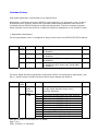
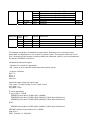
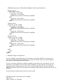
www.triomotion.com
Doc No.:
Version:
Date:
Subject:
Trio Motion Technology Ltd.
Shannon Way, Tewkesbury,
Gloucestershire. GL20 8ND
United Kingdom
Tel:
+44 (0)1684 292333
Fax: +44 (0)1684 297929
1000 Gamma Drive
Suite 206
Pittsburgh, PA 15238
United States of America
Ph: +1 412.968.9744
Fx: +1 412.968.9746
TN20-63
1.0
3rd February 2004
SERCOS Registration and Homing
Application Information
Contents:
Contents:..................................................................................................................... 1
References: ................................................................................................................ 1
Acronyms:................................................................................................................... 1
Introduction:.............................................................................................................. 1
Rockwell ‘Kinetix and Ultra Drives’ – Homing : ........................................... 2
Rockwell ‘Kinetix and Ultra Drives’ – Registration :................................... 4
Sanyodenki Drives (PVSercos): ......................................................................... 6
Yaskawa Drives: ....................................................................................................... 7
References:
1 : SigmaII User’s Manual Design and Maintenance (Manual No. SIE-S800-32.2)
Acronyms:
RTS :
RTC :
Real Time Status bit (flag in the drive telegram status word).
Real Time Control bit (flag in the master telegram control word).
Introduction:
This application note describes how to perform registration and homing procedures over a
SERCOS ring when using a Trio Controller master and the slave drives of several different
manufacturers.
SERCOS Interface Commands from Trio BASIC
Page 1 of 12
TN20_53 Issue 1.0 09/09/04
Rockwell ‘Kinetix and Ultra Drives’ – Homing :
Rockwell drives support the SERCOS ‘control unit controlled homing procedure command’. The
drive latches the z-mark, which the SERCOS master uses to determine the required move to the
home position.
The TrioBASIC ‘regist/mark/reg_pos’ keywords are used to perform the homing procedure,
along with several ‘sercos<>’ commands which are required to initialise the drive. The example
program below illustrates this procedure.
The drive will latch the encoder value (the z-mark) in the ‘Marker Position A’ (IDN 00173) after
a homing procedure command has been started (IDN 00146) and both the home enable (zmark, IDN 00407) and home switch (if necessary, IDN 00400) have been triggered. The control
unit must then move the drive based on this latched position to the required home position.
If Bit 5 of the homing parameter (IDN 00147) is set – meaning do not evaluate the home switch
– the drive is homed on the z-mark. If Bit 5 is cleared – meaning evaluate the home switch –
the drive is homed on the z-mark only after the home switch has been set.
Although the SERCOS specification defines various homing configuration parameters in the
‘Homing Parameter’ (IDN 00147), the Kinetix drives tested in the Trio lab would only latch the
encoder value on the z-mark. It could not be configured to latch the encoder value on the
home-switch.
The drive telegram’s Real Time Status bit 1 (RTS1) reflects the state of the marker pulse –
hence the value 408 (the ‘Reference Marker Pulse Registered’ SERCOS parameter is IDN 00408)
is written to IDN 00305 (The Allocation of Real Time Status Bit 1).
The master telegram’s Real Time Control bit 1 (RTC1) determines whether homing is enabled –
hence value 407 (the Homing enable is SERCOS parameter IDN 00407) is written to IDN 00301
(the Allocation of Real Time Control bit 1.)
Example Homing program:
nslot=0
ndrive=81
ndriveaxis=7
datum_speed=0.25
home_switch = 0
'
PRINT"Homing Drive ..."
'Initialise
SERCOS(5,nslot,ndrive,408,2,0) ‘Reference Marker Pulse Registered
‘Reference Marker Pulse Registered connected to RTS1
SERCOS(5,nslot,ndrive,305,2,408)
SERCOS Interface Commands from Trio BASIC
Page 2 of 12
TN20_53 Issue 1.0 09/09/04
'Homing parameter
IF home_switch THEN
'Drive evaluates homing switch & enable, and homes to z-mark AFTER switch has
'been seen.
'(IDN 174 will latch encoder value when home switch triggered)
SERCOS(5,nslot,ndrive,147,2,$04)
ELSE
'Drive homes to z-mark.
SERCOS(5,nslot,ndrive,147,2,$34)
ENDIF
'Homing enable (407) connected to RTC1
SERCOS(5,nslot,ndrive,301,2,407)
'Homing procedure command 'Start homing in drive.
SERCOS(6,nslot,ndrive,146,10000,1)
BASE(ndriveaxis)
old_speed=SPEED
SPEED=datum_speed
REGIST(1)
'Move until mark seen.
FORWARD
WHILE NOT MARK
WEND
CANCEL
WAIT IDLE
DEFPOS(0)
'Marker Position A now contains latched z-mark position.
SPEED=old_speed
'end homing in drive.
SERCOS(6,nslot,ndrive,146,10000,0)
PRINT"Homing procedure completed"
SERCOS Interface Commands from Trio BASIC
Page 3 of 12
TN20_53 Issue 1.0 09/09/04
Rockwell ‘Kinetix and Ultra Drives’ – Registration :
Rockwell drives support the SERCOS probe procedure command, which is used with the
TrioBASIC ‘regist/mark/reg_pos’ commands to perform registration. Please see the Yaskawa
Section for a detailed discussion of the SERCOS parameters used.
Example Program:
'*********************************************
' AB Kinetix Datum
' program constants
high = 0
low = 1
'Program data
nslot=0
ndrive=81
ndriveaxis=7
datum_speed=0.25
'Trig Config
trig_edge = high
'Begin
'RTC1 to update IDN 405 (Probe 1 enable/disable)
'(Hence controller regist function controls SERCOS probe enable/disable (IDN405))
SERCOS(5,nslot,ndrive,301,2,405)
' IDN 305 : RTS Bit 1 : to trigger on probe 1 latch - either high (409: probe
' 1 positive latched) or low (410: probe 1 negative latched) status.
' IDN 169 : Probe Control Parameter - Set active edge which determines which
' idn the recorded probe value will be stored in (either 130 high or 131 low).
IF trig_edge = high THEN
SERCOS(5,nslot,ndrive,305,2,409)
SERCOS(5,nslot,ndrive,169,2,1)
'ensure idn 130 is in AT telegram.
ELSE
SERCOS(5,nslot,ndrive,305,2,410)
SERCOS(5,nslot,ndrive,169,2,2)
'ensure idn 131 is in AT telegram.
ENDIF
'Initialise registration
BASE(ndriveaxis)
old_speed=SPEED
SPEED=datum_speed
REGIST(1)
'Move until mark seen.
SERCOS Interface Commands from Trio BASIC
Page 4 of 12
TN20_53 Issue 1.0 09/09/04
FORWARD
WHILE NOT MARK
WEND
CANCEL
WAIT IDLE
'Move back to datum position.
MOVEABS(REG_POS)
WAIT IDLE
SPEED=old_speed
SERCOS Interface Commands from Trio BASIC
Page 5 of 12
TN20_53 Issue 1.0 09/09/04
Sanyodenki Drives (PVSercos):
The following program illustrates how to datum a SERCOS axis to the motor Z-mark, using the
‘drive controlled homing procedure command’. It is also possible to datum to a homing switch,
or the master can control the homing procedure (see the drive ‘Installation and Operation’
manual for details.)
'*********************************************
'Datum sequence
BASE(naxis)
SERVO=OFF
WA(500)
'Run homing procedure command – home on z-mark.
SERCOS(6,nslot,ndrive1,148,8000,1)
WA(500)
'Cancel homing procedure command
SERCOS(6,nslot,ndrive1,148,8000,-1)
SERVO=ON
WA(200)
‘Now move from z-mark to home position.
MOVE(-0.037)
WAIT IDLE
DEFPOS(0)
SERCOS Interface Commands from Trio BASIC
Page 6 of 12
TN20_53 Issue 1.0 09/09/04
Yaskawa Drives:
High speed registration is performed by the SigmaII drive.
Registration is achieved using the TrioBASIC ‘mark/regist/reg_pos’ keywords on the z-mark or
an external input. However, before this is possible certain drive parameters have had to be
initialised and the SERCOS telegrams configured appropriately. The three example programs
below illustrate how the drive can be configured to perform registration on the encoder z-mark.
1. Registration Initialisation:
The drive parameter Pn511 is configured to assign a CN1 input to the EXT1/EXT2/EXT3 channel.
Parameter
Pn511
Digit
Place
0
Name
Setting
Description
Default
/DEC
0 to F
8
1
/EXT1
0 to F
2
/EXT2
0 to F
3
/EXT3
0 to F
/DEC origin search signal mapping
8: Disabled
4: Assigned to SI4, active high.
8: Disabled
5: Assigned to SI5, active high.
8: Disabled
6: Assigned to S16, active low (falling edge).
F: Assigned to SI6, active high (rising edge).
8: Disabled
8
8
8
The Input Signal Allocation (parameters Pn50A and Pn50B) are configured as appropriate ( see
Ref 1 ), and the power cycled to the drive before these changes are effective.
Parameter
Pn50A
Digit
Place
0
1
Name
Setting
Description
Default
I/O
Signal
Allocation
Mode
/S-ON
0
1: Signals may be assigned freely.
0:input signal allocation as per servo
amplifier sequence.
0
0
1
2
3
4
5
6
7
8
9
A
Inputs from the SI0 (CN1-40) input
Inputs from the SI1 (CN1-41) input
Inputs from the SI2 (CN1-42) input
Inputs from the SI3 (CN1-43) input
Inputs from the SI4 (CN1-44) input
Inputs from the SI5 (CN1-45) input
Inputs from the SI6 (CN1-46) input
Sets signal ON
Sets signal OFF
Inputs the reverse signal from SI0
Inputs the reverse signal from SI1
0: SI0
SERCOS Interface Commands from Trio BASIC
Page 7 of 12
TN20_53 Issue 1.0 09/09/04
terminal
terminal
terminal
terminal
terminal
terminal
terminal
Parameter
Pn50B
2
3
/P-CON
P-OT
B
C
D
E
F
0 to F
0 to F
Digit
Place
0
1
2
3
Name
Setting
Description
Default
N-OT
/ALM-RST
/P-CL
/N-CL
0
0
0
0
As
As
As
As
3:
4:
5:
6:
to
to
to
to
F
F
F
F
Inputs the
Inputs the
Inputs the
Inputs the
Inputs the
As above
As above
reverse
reverse
reverse
reverse
reverse
signal
signal
signal
signal
signal
from
from
from
from
from
SI2
SI3
SI4
SI5
SI6
above
above
above
above
1: SI1
2: SI2
SI3
SI4
SI5
SI6
The example registration initialisation program below illustrates how to configure these
parameters for registration on the z-mark or external inputs. This program need only be run
once ( and then the drive power cycled to enable the parameter values ) since the parameters
are stored in EEPROM in the drive.
Initialisation Example Program:
' Initialise Drive ready for registration.
' NB - power to drive must be cycled after setting these values.
' program constants
high = 0
low = 1
nslot=0
ndrive=1
'Required trigger mode and signal edge.
'Trig mode - 0:origin(Z)mark,1:ext1,2:ext2,3:ext3
trig_mode = 0
trig_edge = high
'Z-mark registration
IF trig_mode = 0 THEN
SERCOS(5,nslot,ndrive,32768+$511,2,$8888)
SERCOS(5,nslot,ndrive,32768+$50A,2,$8100)' Pn50A Input Selections 1
SERCOS(5,nslot,ndrive,32768+$50B,2,$6548)' Pn50B Input Selections 2
ELSE
SERCOS(5,nslot,ndrive,32768+$50A,2,$8881)' Pn50A Input Selections 1
SERCOS Interface Commands from Trio BASIC
Page 8 of 12
TN20_53 Issue 1.0 09/09/04
SERCOS(5,nslot,ndrive,32768+$50B,2,$8888)' Pn50B Input Selections 2
'External input 1
IF trig_mode=1 THEN
IF trig_edge = high THEN
'Active high - rising edge.
SERCOS(5,nslot,ndrive,32768+$511,2,$88F8)
ELSE
'Active low - falling edge.
SERCOS(5,nslot,ndrive,32768+$511,2,$8848)
ENDIF
'External input 2
ELSEIF trig_mode=2 THEN
IF trig_edge = high THEN
'Active high - rising edge.
SERCOS(5,nslot,ndrive,32768+$511,2,$8F88)
ELSE
'Active low - falling edge.
SERCOS(5,nslot,ndrive,32768+$511,2,$8588)
ENDIF
'External input 3
ELSEIF trig_mode= 3 THEN
IF trig_edge = high THEN
'Active high - rising edge.
SERCOS(5,nslot,ndrive,32768+$511,2,$F888)
ELSE
'Active low - falling edge.
SERCOS(5,nslot,ndrive,32768+$511,2,$6888)
ENDIF
ELSE
'Error
ENDIF
ENDIF
2. SERCOS Telegram Configuration :
For the TrioBASIC ‘mark/regist/reg_pos’ keywords to work with SERCOS it is necessary to
configure the SERCOS network telegrams to include the latched value in the drive telegram
(AT), and to set an appropriate axis ‘atype’.
The AT is set as an ‘application’ telegram enabling the contents to be user defined. The first
parameter in this telegram must be the position feedback, and the second is the positive or
negative latched value as required. Active high (positive edge) latched values are written to
SERCOS parameter IDN 00130, and active low (negative edge) latched values to IDN 00131 by
the drive.
The axis atype will depend upon the drive control mode.
SERCOS Interface Commands from Trio BASIC
Page 9 of 12
TN20_53 Issue 1.0 09/09/04
AType
22
23
Control Mode
Velocity
Position
AT Telegram Contents
Position and latched value
Position and latched value
SERCOS initialisation program snippet – slave drive configured in velocity control mode with
positive latched registration:
SERCOS(5,nslot,ndrive1,15,2,7)'IDN 00015 – application telegrams.
SERCOS(5,nslot,ndrive1,32,2,2)'IDN 00032 Velocity control mode.
SERCOS(5,nslot,ndrive1,16,6,51,130) 'drive telegram - position & positive latch values.
SERCOS(5,nslot,ndrive1,24,6,36) 'master telegram - velocity command.
SERCOS initialisation program snippet – slave drive configured in velocity control mode with
positive latched registration:
ATYPE AXIS(drive1axis)=22 'velocity+latch position
3. Example drive registration program :
Registration shall be possible after having configured the drive parameters and SERCOS
telegrams, brought the SERCOS ring into communications phase 4 (normal operations), and
setup the SERCOS axis on the Trio controller.
The SERCOS Real Time Control (RTC) and Real Time Status (RTS) bits within the master and
drive telegrams are configured to enable/disable registration and to provide latch status
feedback respectively. The drive is informed of the registration mode via IDNs 00169 (Probe
Control Parameter) and the product specific P-IDN 49252.
SERCOS IDN
00301
Name
Allocation of Real Time Control Bit 1
00305
Allocation of Real Time Status Bit 1
00169
Probe Control Parameter
49252
Probe Latch Input
Notes
405 : (IDN 00405 = Probe 1 Enable).
Hence RTC1 controls registration
enable/disable.
409: (IDN 00409 = Probe 1 positive
latched), or
410: (IDN 00410 = Probe 1 negative
latched).
Hence, RTS1 reflects status of latch.
1: Positive edge is latched.
2: Negative edge is latched.
0: z-mark,
1: EXT1,
2: EXT2,
3: EXT3
The Regist command initialises the registration mode on the drive at run time. After the regist
mark has been seen, the ‘mark’ flag will be set and reg_pos will contain the latched regist
position.
SERCOS Interface Commands from Trio BASIC
Page 10 of 12
TN20_53 Issue 1.0 09/09/04
'************************************************************************
'P730 Regist/datum Support
'
'
'
'
'
'
'
'
'
Notes
1. must have initialised drive parameters (Pn511, Pn50A & Pn50B) and cycled power to
the drive before running this program.
2. Active High (positive edge)latch requires IDN 00130 in cyclic data telegram,
(configured in main startup program) and IDN 00305=409 & IDN 00169=1 (configured
below)
3. Active low (negative edge ) latch requires IDN 00131 in telegram, and
IDN 00305=410 & IDN 00169=2
4. you must be running in VELOCITY/POSITION and REG telegram mode !!
' program constants
high = 0
low = 1
'Program data
nslot=0
ndrive=1
ndriveaxis=6
'Trig mode
' 0 = origin(Z)mark,1=ext1,2=ext2,3=ext3
trig_mode = 0
trig_edge = high
'Begin
'RTC1 to update IDN 405 (Probe 1 enable/disable)
'(Hence controller regist function controls SERCOS probe enable/disable (IDN405))
SERCOS(5,nslot,ndrive,301,2,405)
' IDN 305 : RTS Bit 1 : to trigger on probe 1 latch - either high (409: probe
' 1 positive latched) or low (410: probe 1 negative latched) status.
' IDN 169 : Probe Control Parameter - Set active edge which determines which
' idn the recorded probe value will be stored in (either 130 high or 131 low).
IF trig_edge = high THEN
SERCOS(5,nslot,ndrive,305,2,409)
SERCOS(5,nslot,ndrive,169,2,1)
'ensure idn 130 is in AT telegram.
ELSE
SERCOS(5,nslot,ndrive,305,2,410)
SERCOS(5,nslot,ndrive,169,2,2)
'ensure idn 131 is in AT telegram.
ENDIF
'Configure drive latch input (using a P-IDN).
SERCOS(5,nslot,ndrive,49252,2,trig_mode)
'Initialise registration
BASE(ndriveaxis)
SERCOS Interface Commands from Trio BASIC
Page 11 of 12
TN20_53 Issue 1.0 09/09/04
old_speed=SPEED
SPEED=1
REGIST(1)
'Move until mark seen.
FORWARD
WHILE NOT MARK
WEND
CANCEL
WAIT IDLE
'Move back to datum position.
MOVEABS(REG_POS-0.09)
WAIT IDLE
DEFPOS(0)
SPEED=old_speed
SERCOS Interface Commands from Trio BASIC
Page 12 of 12
TN20_53 Issue 1.0 09/09/04