1
User guide
100 mm graphics recorder
Model 5100e
E U ROT H E R M
ε
EUROTHERM
Declaration of Conformity
Manufacturer's name:
Eurotherm Limited
Manufacturer's address
Faraday Close, Worthing, West Sussex,
BN13 3PL, United Kingdom.
Product type:
Industrial graphics recorder
Models:
5100e
Safety specification:
EN61010-1: 1993 / A2:1995
EMC emissions specification:
EN61326
EMC immunity specification:
EN61326
Status level A1 and above
Eurotherm Limited hereby declares that the above products conform to the safety and EMC
specifications listed. Eurotherm Limited further declares that the above products comply
with the EMC Directive 89 / 336 / EEC amended by 93 / 68 / EEC, and also with the Low
Voltage Directive 73 /23 / EEC
Signed:
Dated:
Signed for and on behalf of Eurotherm Limited
Peter de la Nouger de
(Technical Director)
IA249986U580 Issue 1 Jan 2001
© 2004 Eurotherm Limited
All rights are strictly reserved. No part of this document may be reproduced, modified, or transmitted in any form
by any means, nor may it be stored in a retrieval system other than for the purpose to act as an aid in operating the
equipment to which the document relates, without the prior written permission of Eurotherm limited.
Eurotherm Limited pursues a policy of continuous development and product improvement. The specifications in
this document may therefore be changed without notice. The information in this document is given in good faith,
but is intended for guidance only. Eurotherm Limited will accept no responsibility for any losses arising from
errors in this document.
100 MM GRAPHICS RECORDER: USER GUIDE
GRAPHICS RECORDER
USER MANUAL
LIST OF SECTIONS
Section
Page
1 INTRODUCTION . . . . . . . . . . . . . . . . . . . . . . . . . . . . . . . . . . . . . . . . . . . 8
2 INSTALLATION . . . . . . . . . . . . . . . . . . . . . . . . . . . . . . . . . . . . . . . . . . . . . 8
3 PROCESS VARIABLE DISPLAY . . . . . . . . . . . . . . . . . . . . . . . . . . . . . . . . . . 12
4 SETTING UP THE RECORDER . . . . . . . . . . . . . . . . . . . . . . . . . . . . . . . . . . 34
5 FILE . . . . . . . . . . . . . . . . . . . . . . . . . . . . . . . . . . . . . . . . . . . . . . . . . . . . 97
ANNEX A SPECIFICATION . . . . . . . . . . . . . . . . . . . . . . . . . . . . . . . . . . . . 101
ANNEX B REFERENCE . . . . . . . . . . . . . . . . . . . . . . . . . . . . . . . . . . . . . . . 107
INDEX . . . . . . . . . . . . . . . . . . . . . . . . . . . . . . . . . . . . . . . . . . . . . . . . . . . 123
EFFECTIVITY
This manual refers to recorders fitted with software version 3.3. To determine the software version fitted to the recorder, the 'About' screen in the System menu may be accessed as described in section 4.6.5.
For details of Remote Viewer and Modbus Communications see HA028122.
For details of Software and Hardware options see HA028121.
HA027271
Issue 12 Mar 04
User Guide
Page 1
100 MM GRAPHICS RECORDER: USER GUIDE
GRAPHICS RECORDER
USER MANUAL
LIST OF CONTENTS
Section
Page
Safety Notes .......................................................................................................
SYMBOLS USED ON THE RECORDER LABELLING ..................................................
1 INTRODUCTION .................................................................................
1.1 UNPACKING THE RECORDER .......................................................................
2 INSTALLATION ...................................................................................
2.1 MECHANICAL INSTALLATION ......................................................................
2.2 ELECTRICAL INSTALLATION ..........................................................................
2.2.1 Signal wiring .......................................................................................
CONNECTOR WIRING DETAILS ...........................................................
2.2.2 Supply voltage wiring ............................................................................
LINE SUPPLY ........................................................................................
LOW VOLTAGE SUPPLY OPTION ..........................................................
2.3 DISK INSERTION AND REMOVAL .................................................................
3 PROCESS VARIABLE DISPLAY ..............................................................
TRUNCATION OF NUMERIC VALUES ....................................................
CURRENT CHANNEL ALARM ICONS ....................................................
3.1 STATUS BAR ................................................................................................
3.1.1 Current access level .............................................................................
3.1.2 Page name ..........................................................................................
3.1.3 Alarm indicators ..................................................................................
ALARM SUMMARY PAGE .....................................................................
ALARM ACKNOWLEDGEMENT ............................................................
INSTRUMENT ALARMS ........................................................................
CHANNEL ALARM ...............................................................................
CHANGE BATTERY ..............................................................................
3.1.4 Disk icon .............................................................................................
3.1.5 FTP Icon ..............................................................................................
3.1.6 Configuration Locked indicator ..............................................................
3.2 NAVIGATION Keys ......................................................................................
3.2.1 Key functions .......................................................................................
MESSAGE LOG ...................................................................................
3.3 FIRST SWITCH-ON .......................................................................................
3.3.1 Access to Configuration ........................................................................
TEXT STRING ENTRY ............................................................................
3.4 DISPLAY MODES ..........................................................................................
3.4.1 Vertical Trend display ...........................................................................
TIME CHANGE RECORDS ....................................................................
TREND HISTORY ..................................................................................
3.4.2 Horizontal Trend display .......................................................................
3.4.3 Vertical bargraph ..................................................................................
3.4.4 Horizontal bargraph ............................................................................
3.4.5 Numeric ..............................................................................................
3.5 OPERATOR NOTES ......................................................................................
User Guide
Page 2
7
7
8
8
8
8
10
10
10
11
11
11
11
12
13
13
13
13
13
14
14
15
16
17
17
17
17
17
18
18
19
21
22
23
25
25
26
26
28
30
31
32
33
HA027271
Issue 12 Mar 04
100 MM GRAPHICS RECORDER: USER GUIDE
LIST OF CONTENTS (Cont.)
Section
Page
4 SETTING UP THE RECORDER ...............................................................
4.1 ARCHIVE .....................................................................................................
4.1.1 Archive to disk .....................................................................................
4.1.2 Remote archiving (FTP transfer) ..............................................................
4.2 SAVE / RESTORE .........................................................................................
4.2.1 Save ...................................................................................................
SAVE FOR PRE VERSION 1.8 ................................................................
4.2.2 Restore ................................................................................................
4.2.3 New ...................................................................................................
4.2.4 Text ....................................................................................................
4.2.5 Import User Linearisation ......................................................................
4.2.6 Export User Linearisation ......................................................................
4.3 CONFIGURATION ........................................................................................
4.3.1 Instrument configuration ........................................................................
INSTRUMENT NAME ...........................................................................
NORMAL/SAVER DISPLAY ....................................................................
SAVE AFTER ........................................................................................
MODBUS ADDRESS .............................................................................
MODBUS SECURITY DISABLED .............................................................
COMMS CHANNEL TIMEOUT ..............................................................
PRESET HOUR .....................................................................................
PRESET MINUTE ..................................................................................
4.3.2 Group configuration .............................................................................
GROUP NUMBER ................................................................................
TREND UNITS ......................................................................................
DESCRIPTOR .......................................................................................
A/B SWITCHING ................................................................................
TREND SPEED/TREND INTERVAL ...........................................................
GRID TYPE ..........................................................................................
RECORDING ENABLE ..........................................................................
RECORDING SPEED/RECORDING INTERVAL .........................................
TREND HISTORY DURATION ................................................................
ARCHIVE TO MEDIA/ARCHIVE VIA FTP .................................................
ALARM MESSAGE ...............................................................................
ACK MESSAGE ...................................................................................
GROUP CONTENTS ............................................................................
4.3.3 Channel/Alarm configuration ................................................................
CHANNEL NUMBER ............................................................................
VALUE ................................................................................................
INPUT TYPE .........................................................................................
LIN TYPE .............................................................................................
INPUT LOW ........................................................................................
INPUT HIGH ........................................................................................
SHUNT ...............................................................................................
RANGE LOW ......................................................................................
RANGE HIGH .....................................................................................
RANGE UNITS ....................................................................................
SCALED ..............................................................................................
OFFSET ...............................................................................................
SCALE TYPE ........................................................................................
FILTER .................................................................................................
BREAK RESPONSE ...............................................................................
COLD JUNCTION COMPENSATION (CJC) ............................................
DESCRIPTOR .......................................................................................
A/B SWITCHING ................................................................................
SPANNED ...........................................................................................
ZONE .................................................................................................
PV FORMAT ........................................................................................
34
35
35
36
37
38
38
38
38
38
39
39
40
43
43
43
43
43
43
43
43
43
44
44
44
44
44
45
45
46
46
46
46
46
47
47
48
49
49
49
49
49
49
49
50
50
50
50
50
50
51
52
52
52
52
52
53
53
Cont...
HA027271
Issue 12 Mar 04
User Guide
Page 3
100 MM GRAPHICS RECORDER: USER GUIDE
LIST OF CONTENTS (Cont.)
Section
Page
4.3.3 Channnel/Alarm Configuration (Cont.)
4.3.4
4.3.5
4.3.6
4.3.7
4.3.8
4.3.9
MAXIMUM DECIMAL DIGITS ................................................................
COLOUR ............................................................................................
ALARM NUMBER .................................................................................
ENABLE ..............................................................................................
TYPE ...................................................................................................
PARAMETERS ......................................................................................
EXAMPLE ............................................................................................
JOB NUMBER ......................................................................................
CATEGORY .........................................................................................
WHILE/ON .........................................................................................
ALARM MESSAGES .............................................................................
Views Configuration .............................................................................
HOME TIMEOUT .................................................................................
HOME GROUP ....................................................................................
DARK TREND/DARK HISTORY BACKGROUND ......................................
SCOPE ...............................................................................................
GROUP ...............................................................................................
DISPLAY ENABLED ...............................................................................
HOME PAGE .......................................................................................
DISPLAY MODE ENABLING ..................................................................
Archive configuration ...........................................................................
COMPRESSION ..................................................................................
FLASH SIZE .........................................................................................
SHORTEST TREND HISTORY / DURATION .............................................
CSV CHECKBOXES, DATE/TIME FORMAT .............................................
SHOW ...............................................................................................
ARCHIVE TO MEDIA ............................................................................
MEDIA FILE FORMAT/FTP FILE FORMAT .................................................
MEDIA FULL OPERATION .....................................................................
MEDIA SIZE ........................................................................................
DISK ARCHIVE CAPACITY ....................................................................
MEDIA FULL EVENT LIMIT .....................................................................
ARCHIVE TO REMOTE .........................................................................
REMOTE PATH .....................................................................................
PRIMARY REMOTE HOST .....................................................................
PRIMARY LOGIN NAME/PASSWORD ...................................................
SECONDARY REMOTE HOST/LOGIN/PASSWORD ...............................
CSV OPTION ......................................................................................
Event configuration ..............................................................................
EVENT NUMBER ..................................................................................
SOURCE TYPES ...................................................................................
SOURCE 1 SENSE ...............................................................................
OPERATOR ..........................................................................................
SOURCE 2 SENSE ...............................................................................
DESCRIPTOR .......................................................................................
JOB NUMBER ......................................................................................
CATEGORY .........................................................................................
WHILE/ON .........................................................................................
EVENT EXAMPLE .................................................................................
Messages ............................................................................................
MESSAGE ENTRY ................................................................................
CONFIGURABLE PARAMETERS .............................................................
EXAMPLE ............................................................................................
User Linearisation Tables .......................................................................
CONFIGURATION PARAMETERS ..........................................................
Options ...............................................................................................
53
53
54
54
54
55
55
57
57
57
57
58
58
58
58
59
59
59
59
59
60
61
61
61
61
61
61
61
62
62
62
62
62
62
63
63
63
63
65
65
65
66
66
66
67
67
67
67
67
68
68
68
70
71
71
73
Cont...
User Guide
Page 4
HA027271
Issue 12 Mar 04
100 MM GRAPHICS RECORDER: USER GUIDE
LIST OF CONTENTS (Cont.)
Section
Page
4.4 SECURITY ....................................................................................................
4.4.1 Access levels .......................................................................................
SETTING PERMISSIONS .......................................................................
ACCESS WHEN: .................................................................................
NEW PASSWORD/RETYPE PASSWORD ................................................
CONNECT FROM REMOTE ..................................................................
REMOTE USER NAME/PASSWORD ......................................................
LOGIN DISABLED ................................................................................
EDIT OWN PASSWORD ......................................................................
CHANGE ALARM SETPOINTS ..............................................................
ACKNOWLEDGE ALARMS ...................................................................
EDIT MATHS CONSTANT .....................................................................
PRESET TOTALISERS .............................................................................
PRESET COUNTERS .............................................................................
START/RESET TIMERS ...........................................................................
SET CLOCK .........................................................................................
ADJUST INPUTS ...................................................................................
ARCHIVING CONTROL ........................................................................
SAVE/RESTORE ...................................................................................
PASTE/DELETE FILES ............................................................................
FULL CONFIGURATION .......................................................................
FULL SECURITY ....................................................................................
EVENT PERMISSION 1 .........................................................................
EVENT PERMISSION 2 TO 5 ................................................................
FORCE CHANGE OF PASSWORD ........................................................
4.4.2 Management (option) ...........................................................................
4.4.3 Add user .............................................................................................
NEW USER ID .....................................................................................
NEW FULL USER NAME .......................................................................
NEW PASSWORD/RETYPE PASSWORD ................................................
BASED ON .........................................................................................
4.4.4 Remove user ........................................................................................
4.5 NETWORK CONFIGURATION ......................................................................
4.5.1 Address ..............................................................................................
INSTRUMENT NUMBER/MAC ADDRESS ...............................................
IP ADDRESS LOOKUP ..........................................................................
BOOTP TIMEOUT ................................................................................
IP ADDRESS ........................................................................................
SUBNET MASK ....................................................................................
DEFAULT GATEWAY .............................................................................
SNTP ENABLE .....................................................................................
SNTP SERVER ......................................................................................
4.5.2 Name .................................................................................................
LOCAL HOST ......................................................................................
DOMAIN ............................................................................................
DOMAIN NAME SERVICE (DNS) ..........................................................
PRIMARY/SECONDARY DNS SERVER ...................................................
4.6 SYSTEM ......................................................................................................
4.6.1 Clock ..................................................................................................
4.6.2 Locale .................................................................................................
4.6.3 Keycode ..............................................................................................
4.6.4 Input adjust .........................................................................................
ADJUST PROCEDURE ...........................................................................
4.6.5 About .................................................................................................
INSTRUMENT VARIANT ........................................................................
CONFIG REVISION .............................................................................
SECURITY REVISION ............................................................................
SUPPORT FILE ......................................................................................
CLEAN \USER FOLDER ........................................................................
74
74
75
75
75
75
76
76
76
76
76
76
76
76
76
76
77
77
77
77
77
77
77
77
77
78
79
79
79
79
79
79
80
80
80
80
80
80
81
81
81
81
82
82
82
82
82
83
84
84
84
84
86
87
87
87
87
88
88
Cont...
HA027271
Issue 12 Mar 04
User Guide
Page 5
100 MM GRAPHICS RECORDER: USER GUIDE
LIST OF CONTENTS (Cont.)
Section
Page
4.6.6 Copy ..................................................................................................
CONFIGURABLE PARAMETERS .............................................................
COPY RULES .......................................................................................
4.7 JOBS ..........................................................................................................
4.7.1 No Action ...........................................................................................
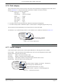
4.7.2 Drive relay ..........................................................................................
4.7.3 Totaliser category .................................................................................
4.7.4 Message category ...............................................................................
4.7.5 Maths Category ...................................................................................
4.7.6 Clock category ....................................................................................
4.7.7 Counter category .................................................................................
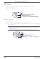
4.7.8 Timer jobs ...........................................................................................
4.7.9 Recording jobs ....................................................................................
4.7.10 Trend jobs .........................................................................................
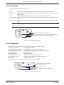
4.7.11 Alarm jobs ........................................................................................
4.7.12 Archive jobs ......................................................................................
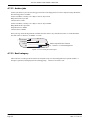
4.7.13 Email category ..................................................................................
5. FILE ..................................................................................................
5.1 FILER OPTION MENU KEYS ..........................................................................
5.2 THE HIDE KEY .............................................................................................
5.3 FILE STRUCTURE ..........................................................................................
5.3.1 Software versions prior to 3.1 ...............................................................
5.3.2 Software versions 3.1 onwards .............................................................
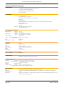
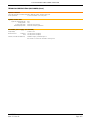
Annex A: SPECIFICATION ......................................................................
TECHNICAL SPECIFICATION (Recorder) ................................................................
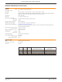
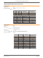
TECHNICAL SPECIFICATION (Universal inputs) ......................................................
TECHNICAL SPECIFICATION (Ethernet/Relay output board option) ..........................
Annex B: REFERENCE ............................................................................
B1 DIAGNOSTICS DISPLAY ................................................................................
B1.1 DISPLAY DETAILS ...................................................................................
MAC ETHERNET ADDRESS ...................................................................
COLOUR TEST BARS ............................................................................
SOFTWARE VERSION NUMBER ............................................................
SELF-TEST STATUS BARS .......................................................................
CIRCUIT BOARDS FITTED .....................................................................
TOUCH CAL ........................................................................................
DETAIL ................................................................................................
B2 SCREEN CALIBRATION (OFFSET CORRECTION) ..............................................
B3 PREVENTIVE MAINTENANCE ........................................................................
B3.1 Touch Screen Cleaning ..........................................................................
B3.2 Maintenance schedule ...........................................................................
B3.3 Battery replacement procedure ...............................................................
B4 OPTION ENABLING ......................................................................................
B4.1 Instrument Number ................................................................................
B4.2 Key Code .............................................................................................
B4.3 KeyCode File ........................................................................................
B5 COLOUR SELECTION ....................................................................................
B6 TCP Port Numbers .........................................................................................
B7 TIME ZONES ................................................................................................
B8 MENU STRUCTURE .......................................................................................
Index ....................................................................................................
User Guide
Page 6
89
89
90
91
91
91
91
92
92
93
93
94
94
95
95
96
96
97
97
97
99
99
99
101
102
104
106
107
107
107
107
107
107
107
108
108
108
109
109
109
110
110
111
111
111
111
112
114
115
117
123
HA027271
Issue 12 Mar 04
100 MM GRAPHICS RECORDER: USER GUIDE
SAFETY NOTES
WARNING
Any interruption of the protective conductor inside or outside the apparatus, or disconnection of the
protective earth terminal is likely to make the apparatus dangerous under some fault conditions. Intentional interruption is prohibited.
Note: in order to comply with the requirements of safety standard BS EN61010, the recorder shall have one
of the following as a disconnecting device, fitted within easy reach of the operator, and labelled as the disconnecting device.
a
b.
c.
A switch or circuit breaker which complies with the requirements of IEC947-1 and IEC947-3
A separable coupler which can be disconnected without the use of a tool
A separable plug, without a locking device, to mate with a socket outlet in the building.
1. Before any other connection is made, the protective earth terminal shall be connected to a protective conductor.
The mains (supply voltage) wiring must be terminated within the connector in such a way that, should it slip in
the cable clamp, the Earth wire would be the last wire to become disconnected.
2. In the case of portable equipment, the protective earth terminal must remain connected (even if the recorder is
isolated from the mains supply), if any of the I/O circuits are connected to hazardous voltages*.
3. The mains supply fuse within the power supply is not replaceable. If it is suspected that the fuse is faulty, the
manufacturer's local service centre should be contacted for advice.
4. Whenever it is likely that protection has been impaired, the unit shall be made inoperative, and secured against
accidental operation. The manufacturer's nearest service centre should be contacted for advice.
5. Any adjustment, maintenance and repair of the opened apparatus under voltage, should be avoided as far as possible and, if inevitable, shall be carried out only by a skilled person who is aware of the hazard involved.
6. Where conductive pollution (e.g. condensation, carbon dust) is likely, adequate air conditioning/filtering/sealing
etc. must be installed in the recorder enclosure.
7. Signal and supply voltage wiring should be kept separate from one another. Where this is impractical, shielded
cables should be used for the signal wiring.
8. If the equipment is used in a manner not specified by the manufacturer, the protection provided by the equipment
might be impaired.
* A full definition of 'Hazardous' voltages appears under 'Hazardous live' in BS EN61010. Briefly, under normal operating conditions, hazardous voltages are defined as being > 30V RMS (42.2V peak) or > 60V dc.
SYMBOLS USED ON THE RECORDER LABELLING
One or more of the symbols below may appear as a part of the recorder labelling.
!
Refer to the manual for instructions
Protective earth
This recorder for ac supply only
This recorder for dc supply only
This recorder for either ac or dc supply
Risk of electric shock
HA027271
Issue 12 Mar 04
User Guide
Page 7
100 MM GRAPHICS RECORDER: USER GUIDE
USER MANUAL
1 INTRODUCTION
This document describes the installation, operation and configuration of a 100mm graphics recorder. The recorder
has the facility for FTP transfer and Remote viewer connection if the Ethernet option is fitted.
The recorder instrument time can be updated from a unicast (i.e. point-to-point) Simple Network Time Protocol
(SNTP) server and is also itself an SNTP server. SNTP time is based on elapsed seconds since 00:00 hrs on 1st Jan
1900 GMT and is affected neither by time zones nor by daylight saving. The relevant TCP port number is 123. See
sections 4.3.1 (Instrument configuration), 4.5.1 (Network Address configuration) and B6 in Annex B, for more details.
1.1 UNPACKING THE RECORDER
The recorder is despatched in a special pack, designed to give adequate protection during transit. Should the outer
box show signs of damage, it should be opened immediately, and the recorder examined. If there is evidence of damage, the instrument should not be operated and the local representative contacted for instructions. After the recorder
has been removed from its packing, the packing should be examined to ensure that all accessories and documentation
have been removed. The packing should then be stored against future transport requirements.
2 INSTALLATION
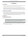
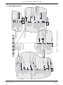
2.1 MECHANICAL INSTALLATION
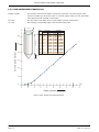
Figure 2.1 gives installation details.
Note: It is recommended that the rear face of the panel be centre-punched at suitable positions to locate the
tips of the case clamps. Otherwise, particularly on smooth surfaces, the clamps can 'wander' as they are
tightened, leading to inefficient clamping and possible damage to the recorder mounting slots.
The unit is inserted through the panel aperture from the front of the panel. With the weight of the recorder supported,
a panel clamp is inserted into each of the mounting slots (one each on the left- and right-hand sides). The jacking
screws are then tightened sufficiently to clamp the recorder into position. EXCESS FORCE SHOULD NOT BE
USED IN TIGHTENING THESE SCREWS.
User Guide
Page 8
HA027271
Issue 12 Mar 04
100 MM GRAPHICS RECORDER: USER GUIDE
2 INSTALLATION (Cont.)
Lift then pull to open
flap for mass storage
access
x
138 x 138mm
(-0.0 + 1.0)
View on right hand
side
137mm (5.4in)
247.5mm (9.75in) (STC)
213mm (8.39in)
70 mm
(2.76 in)
144mm (5.67in)
144mm (5.67in)
110 mm (4.33 in )
Max. 30mm
(1.2 in)
399 mm (15.7in) (LTC open)
284mm (11.18in) (LTC closed)
Mounting slot
(Left hand side)
Panel thickness
(25.4mm (1 in) max)
LTC = long terminal cover
STC = Short Terminal cover
137mm
(5.4in)
View on under side
5.44 x 5.44 in
(-0.00 + 0.04)
y
Panel cutout
Minimum recommended inter-unit spacing
Top/bottom clamps
x = 10 mm (0.4 in)
y = 15mm (0.6 inch)
Vertical
Side clamps
x = 15mm (0.6 inch)
y = 10 mm (0.4 in)
a˚
b˚
Panel clamping
MAXIMUM INSTALLED ANGLE
a = b = 15 degrees max
Figure 2.1 Mechanical installation details - small frame unit
HA027271
Issue 12 Mar 04
User Guide
Page 9
100 MM GRAPHICS RECORDER: USER GUIDE
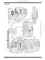
2.2 ELECTRICAL INSTALLATION
8
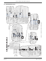
2.2.1 Signal wiring
1
Ethernet 1
1 Relay
connector
connector
(option)
(option)
Non-isolated
TRS (option)
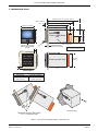
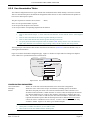
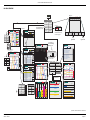
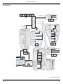
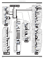
Figure 2.2.1a shows connector locations for the input
channel and for the optional relay output/Ethernet board
CONNECTOR WIRING DETAILS
Maximum wire size (inputs) = 4.13mm2 (11 AWG)
Maximum wire size (relay) = 1.5 mm2 (16 AWG)
Max. wire size (non-isolated TRS) = 1.5 mm2 (16 AWG)
Minimum wire size = 0.081mm2 (28 AWG)
Design torque = 0.8Nm.
Supply
voltage
connector
Input channel connector
1
Figures 2.2.1b, c and d show details of input board wiring,
relay output option wiring and Non isolated Transmitter
Power supply option pinout, respectively. Wiring details
for other options is to be found in the relevant Option
description later in the manual.
22
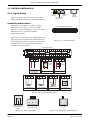
Figure 2.2.1a Connector locations
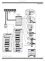
Input board pinouts
1
2 3 4
Channel 1
5 6 7
Channel 2
8 9 10 11 12 13 14 15 16 17 18 19 20 21 22
Channel 3
Channel 4 Channel 5 Channel 6
V+ V- I
V+ V- I
V+ V- I
V+ V-
I
Cold
junction
V+ V-
V+ V- I
V+ V- I
I
V+ V-
Attenuator
assembly
+
-
+
±10 V dc
Thermocouples
dc millivolts
V+ V-
I
-
I
I
Shunt
assembly
+
±100 V dc
V+ V-
V+ V- I
-
DC milliamps
V+ V-
I
V+ V-
I
nc
com
RTD
RTD
3-wire resistance
thermometer
2-wire resistance
thermometer
no
Potentiometer
Minimum contact = 60msec
Potentiometer
Contact closure
(Not channel 1)
Figure 2.2.1b Input board wiring details
nc
no
com
1
2 3
Contacts shown in
power off/alarm
state
1
2
3
(NC) (Com) (NO)
Figure 2.2.1c Relay wiring details
User Guide
Page 10
1
(+V)
2
(0V)
Figure 2.2.1d Non-isolated TRS wiring details
HA027271
Issue 12 Mar 04
100 MM GRAPHICS RECORDER: USER GUIDE
2.2.2 Supply voltage wiring
WARNING
DC supply voltages must never be applied to recorders fitted with isolated transmitter power supplies.
Note: The minimum recommended wire size is 16/0.2 (0.5mm2).
LINE SUPPLY
The supply voltage to the recorder is terminated using an IEC socket which is connected to the mating plug at the rear
of the recorder. The recorder is suitable for use with all ac voltages between 85 and 265 V RMS (47 to 63 Hz), and
requires 60 VA max. power. For recorders without transmitter power supplies, supply voltages of between 110V dc
and 370V dc may also be used.
LOW VOLTAGE SUPPLY OPTION
Earth
Not suitable for recorders fitted with the isolated transmitter power supply
+V or ac
0V or ac
option.
The low voltage supply option is terminated at a three-pin connector (plug
mounted on recorder - socket on supply cable) as shown in figure 2.2.2.
The option allows the use of ac or dc supplies with the following characteristics:
AC:
20 to 42V RMS (45 to 400 Hz)
Figure 2.2.2 Low voltage supply pinout
DC:
20 to 54V (See warning above)
Power: 60VA max.
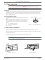
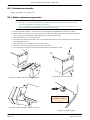
2.3 DISK INSERTION AND REMOVAL
The disk slot is located below the recorder screen, and is protected by a flap as shown in figure 2.1, above.
In order to access the disk slot, the bottom of the central part of the flap is lifted (figure 2.3a) and then used as a handle to pull the main flap open.
If a disk is already fitted, it is removed by pressing on the eject button (figure 2.3b).
Note: Before disk removal, archiving should be suspended (section 4.1) (wait for the green LED on the disk
drive to be extinguished), otherwise data might be lost.
Figure 2.3a Disk access
HA027271
Issue 12 Mar 04
Figure 2.3b Disk eject
User Guide
Page 11
100 MM GRAPHICS RECORDER: USER GUIDE
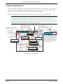
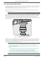
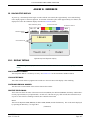
3 PROCESS VARIABLE DISPLAY
The operator interface consists of a touch-sensitive screen, showing either process variable values in one of a number
of formats, or, showing configuration or operational details for use in setting up the recorder. This section (3) describes the process variable displays. Section 4 describes the Configuration displays.
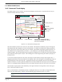
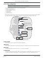
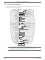
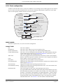
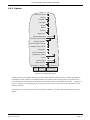
Figure 3, below, depicts a typical trend display and gives details of the various areas of the display page.
Note: Dialogue boxes, message boxes etc. cause Process Variable displays to 'freeze' for as long as the box is
on display. Root and Option menus (amongst others) time-out (i.e. are removed from the display) after
approximately one minute. Messages, however, are displayed until the operator takes action to remove them.
It should be noted, especially, that several message boxes may be active at one time, but only the oldest one is
visible, until it is removed to reveal the 'next oldest' message, and so on.
Root menu key with Current
access level or user full name
Current channel's
descriptor and
trace colour
Current channel's
scale
Battery warning
Channel alarm
Instrument alarm
Page Name
Frederick Bl...
Disk icon
Group Name
Channel 1
11:52:59
29/01/04
99%
˚C
Channel value
0.0000
Channel(s)
configured 'Off'
FTP activity
Configuration Locked indicator
Current time/date
35.0000
Alarm threshold
marker (Abs Hi)
Current trace
alarm icons
Current trace icon
(diamond shape)
Non-current trace
icon
11:44:49
29/01/04
An animated bar appears over the
date, when the recorder is busy.
Though normally pale blue, the bar
is gold-coloured when the recorder configuration is being updated
via the Remote Viewer.
Time/Date stamp
29/01/04 11:33:37 Alarm(s) off 2 (1)
29/01/04 11:31:39 Alarm(s) on 2 (1)
Channel 2 alarm 1
on / off messages
11:31:29
29/01/04
Figure 3 Trend display definitions
User Guide
Page 12
HA027271
Issue 12 Mar 04
100 MM GRAPHICS RECORDER: USER GUIDE
3 PROCESS VARIABLE DISPLAY (Cont.)
TRUNCATION OF NUMERIC VALUES
If the amount of space on the display page is insufficient to display the full width of the process variable or scale
value, then the displayed value is rounded down and the number of decimal places reduced. If the available space is
still too restricted, the value is displayed in 'Scientific' format, or if this is still too wide, the final visible character of
the integer part of the display is replaced by a '?'.
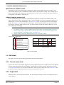
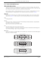
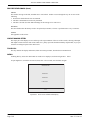
CURRENT CHANNEL ALARM ICONS
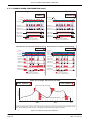
In each of the different types of PV display, each channel's faceplate give the status of the channel's alarms. This
status is shown by one of the icons depicted in table 3, either off, flashing (if it is active and unacknowledged) or on
continuously (if it is active and acknowledged). See section 3.1.3, below, for a description of how to acknowledge
alarms, and section 4.3.3 for a description of the alarm types. Absolute alarm threshold icons and deviation-alarm
bars appear in any display which includes a scale. For deviation alarms, the bar stretches from (Reference - Deviation) to (Reference + Deviation).
Notes
1. For software versions 2.3 onwards, 32MB versions of the recorder come with four alarms per point, instead of two per point as supplied with previous software versions. The System/About display can be
used establish what size of DRAM s fitted - see section 4.6.5.
2. 'Trigger' alarms do not display threshold marks or bars, or faceplate symbols.
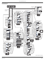
4-alarm units
2-alarm units
Absolute High
Absolute Absolute Deviation Rate of
low
high
In / Out change
Absolute Low
d R d
No
Horizontal
indication
scales
Vertical
No
R
indication
scales
For Deviation alarms, R = Reference; d = deviation
d d
Deviation in
Deviation out
Rate-of-change Rising
Rate-of-change Falling
Faceplate symbols
Scale symbols
Table 3 Alarm symbols
3.1 STATUS BAR
This appears across the top of the display, and contains the items described below.
3.1.1 Current access level
There are four access levels available (Logged out, Operator, Engineer and Service), and the current level is displayed
in this key at the top left hand corner of the display. Touching this key calls the root menu as described in section
3.2.1 (Key functions) below. If a user has been added in the 'Add User' part of the Security setup (section 4.4.3), then
the 'Full User Name' is displayed (truncated if necessary) instead of the access level.
3.1.2 Page name
Initially this shows the current group's descriptor. The name changes according to context for example 'Operator' or
'Config-Archive'.
HA027271
Issue 12 Mar 04
User Guide
Page 13
100 MM GRAPHICS RECORDER: USER GUIDE
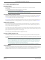
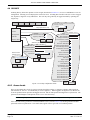
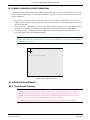
3.1.3 Alarm indicators
This area of the display can contain up to four icons: Instrument alarm, Channel alarm, Battery change, Disk status.
Pressing this area of the screen calls a pop-up display (figure 3.1.3a) allowing the user to view messages to acknowledge all channel alarms, or to display the Alarm Summary page. Also incorporated in this display is a slider control
allowing the user to optimise the display contrast for the local environment. For channel alarm symbols, refer to 'Current Trace Alarm Icons', above.
ALARM SUMMARY PAGE
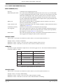
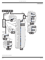
As shown in figure 3.1.3a, below, the alarm summary page contains the following information:
1. Alarm identifier. This appears as a point ID, followed by the relevant alarm number in parentheses. For example, Alarm 1 on maths channel 6 would appear as: D6 (1). Maths channels are prefixed by 'D'. Totalisers are
prefixed by 'T' and Counters are prefixed by 'C'. Input channels are not prefixed.
2 Alarm threshold for absolute alarms only
3 The current process value for the point
4 An alarm symbol (see Table 3). Alarm symbols flash until acknowledged.
Notes:
1. Alarms are always listed in Point/Alarm order with input channels first, followed by derived channels, totalisers and counters, if these options are fitted.
2 When the alarm source returns to its non-alarm state: Unlatched alarms are removed from the list
whether or not they have been acknowledged; latched alarms remain displayed until acknowledged.
See section 4.3.3 for a description of alarm types and actions.
3. There are no time or history components associated with the Alarm Summary. If Alarm messages have
been enabled in the relevant group's configuration (section 4.3.2), then alarm initiation/acknowledgement
times and dates can be found from the trend and trend history displays, described in section 3.4, or in
Message log, described in section 3.2.1.
4. If an alarm is active on a channel which is not included in either group, then although the channel alarm
symbol will flash, the alarm will not appear in the alarm summary pages.
Touch Alarm area
(e.g. channel alarm symbol)
Alarm & Message options
Instrument Alarm Summary
Instrument Alarm Summary
Ack all Alarms
Maths channel Failure
network boot failure
Alarm Summary
See section 3.2.1 for
Message Log details
Message Log
Ok
Display Contrast
Ack all Alarms
Confirm acknowledge of alarms?
The 'Goto Group' window does not appear
for single group
recorders.
Goto Group
Yes
Group 1
No
Group 2
Touch alarm to
call 'Acknowledge'
dialogue box.
Alarm Summary
1 (1)
2 (1)
2 (2)
3 (1)
4 (1)
Water temp 1a
Water temp 1b
Water temp 1b
0il pressure
Transfer
Channel no.(alarm no.)
Channel descriptor
60.0000
30.0000
10.0000
250.0000
Ack Alarm
Confirm acknowledge of alarm?
68.5277 C
23.4531 C
15.7773 C
260.3425PSI
15.3678
Yes
No
Alarm type symbol
Setpoint value
Current process value
(Absolute alarms only)
Figure 3.1.3a Alarm and message options display and contrast control
User Guide
Page 14
HA027271
Issue 12 Mar 04
100 MM GRAPHICS RECORDER: USER GUIDE
3.1.3 ALARM INDICATORS (Cont.)
ALARM ACKNOWLEDGEMENT
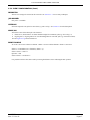
Alarms can be acknowledged globally (all alarms), individually or on a group basis.
ALL ALARMS
To acknowledge all active alarms, touch (e.g.) the channel alarm icon at the top of the screen. From the resulting popup menu, select 'Ack all Alarms', then finally, touch 'Yes' in the resulting pop-up confirmation box. Figure 3.1.3a,
above, attempts to show this process.
INDIVIDUAL ALARMS
Individual alarms are acknowledged from the alarm summary page by touching the relevant item (highlights yellow),
then touching 'Yes' in the resulting pop-up confirmation box. Figure 3.1.3a, above, attempts to show this process.
GROUP ALARMS
For recorders with multiple groups, alarms can be acknowledged on a group basis by calling the alarm summary page
for the relevant group, then pressing the Root menu Options key (section 3.2), the 'Ack Group Alarms' key and finally,
'Yes' in the resulting pop-up confirmation box. Figure 3.1.3b, below, attempts to show this process.
Engineer
Alarm Summary
1 (1)
2 (1)
2 (2)
3 (1)
4 (1)
Root menu
Water temp 1a
Water temp 1b
Home
Water temp 1b
0il pressure
Transfer
File
60.0000
68.5277 C
30.0000
23.4531 C
Operator
10.0000
15.7773 C
250.0000
260.3425PSI
15.3678
Goto View
Goto Group
Login
Options
Option menu
Note
Ack Group Alarms
Ack Group Alarms
Confirm acknowledge of alarm?
Yes
No
Figure 3.1.3b Group Alarm acknowledgement
HA027271
Issue 12 Mar 04
User Guide
Page 15
100 MM GRAPHICS RECORDER: USER GUIDE
3.1.3 ALARM INDICATORS (Cont.)
INSTRUMENT ALARMS
This indicator appears, flashing, if any of the following alarms are active. The Instrument alarm summary page, described above, allows the user to view any such alarms.
Archive failed -(message)
Message explains archive failure - due to disk being missing, write protected,
faulty, full etc.
Battery-backed RAM cleared
This message appears if the battery has failed, and the unit has been switched off.
Channel failure
Indicates a hardware failure in the input channel circuit
Channel error
Indicates a hardware failure in the channel circuit or in the internal CJ temperature
measurement
Clock failure
Internal clock was corrupt at power up, or the time has never been set. Can be
caused by battery failure, in which case the battery icon will also be visible. The
error is cleared by setting the time and date. Server time forced to 00:00 1/1/1900.
Floppy disk worn
Appears if a number of attempts had to be made before write to the disk was successful. No data is lost, but the disk should be replaced as soon as is practicable.
Floppy disk corrupt
This appears if all attempts to write to the disk fail. In such a case, some data may
be lost. If the damaged area of the disk is in the system part of the disk, it might
appear to the recorder that it is unformatted, and the disk icon will disappear. The
disk should be replaced immediately.
FTP Primary Server Failure
This error is set if the recorder fails, after two attempts, to establish communications with the primary server as defined in Archive Configuration (section 4.3.5).
After the second attempt has failed, the Secondary server is tried.
FTP Secondary Server Failure
This error is set if the recorder fails, after two attempts, to establish communications with the secondary server as defined in Archive Configuration (section 4.3.5).
See also 'FTP Primary Server Failure, above.
Insufficient non-volatile memory...
There is insufficient memory available for the configuration. Sometimes caused by
the use of the Rolling Average maths function.
Internal flash: \user\ required repair
Error found (in the internal file system) at power-up, and corrected.
Internal flash: \system\ required repair Error found (in the internal file system) at power-up, and corrected.
Internal flash: \history\ required repair Error found (in the internal file system) at power-up, and corrected.
Maths Channel failure
Appears, for example, if the divisor of a divide function passes through zero.
Network boot failure
The recorder is unable to establish connection with the bootP server. This might be
caused by, for example, cable failure, network hardware failure, etc.
Recording failure - (message)
Message explains recording failure e.g. file error, internal overflow etc.
Removable media failure
This error is set if the disk is corrupt, wrongly formatted etc. Becomes active only
when an Archive is attempted.
Removable media full
Floppy disk or PC card full. Becomes active only when an Archive is in progress.
SNTP server failure
This alarm is set if:a) the year received from the server is < 2001 or > 2035 or
b) the configured SNTP server cannot be accessed
Time synchronisation failure
Set if 5 or more 'Time change events' are caused by the SNTP server within 24 hrs.
A 'Time change event' is defined as occuring whenever the recorder time is found
to be more than 2 seconds different from the server time. The alarm does not appear until 24 hours after the first of the five-or-more Time Change events occurred.
User Guide
Page 16
HA027271
Issue 12 Mar 04
100 MM GRAPHICS RECORDER: USER GUIDE
3.1.3 ALARM INDICATORS (Cont.)
CHANNEL ALARM
This red 'bell' indicator appears if any channel is in alarm. The symbol is illuminated continuously if all alarms are
acknowledged or flashes if any active alarm is unacknowledged. Refer to ALARM ACKNOWLEDGEMENT, above,
for details of how to acknowledge alarms.
Note: If a point is in alarm, but not enabled in either group, the point's alarm symbol will behave as described
above, but the alarm will not appear in the Alarm Summary displays. Such channels can be acknowledged
only by using Ack All Alarms as described in section 3.1.2, above.
CHANGE BATTERY
This flashing indicator first appears when the battery voltage indicates that the battery is approaching the end of its
useful life. The indicator continues to flash until the battery is replaced (Annex B, section B3.2). The indicator does
not appear if the battery is not fitted.
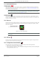
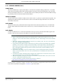
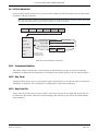
3.1.4 Disk icon
This shows the free space available on the disk. The disk icon appears soon after a disk or data card is inserted. Only
archiving activity is indicated; during archiving, the central area of the disk icon flashes green, regularly. No other
disk activity is indicated.
This area of the icon flashes
green/white during archive
(or is solid red at remote viewer).
99%
Figure 3.1.4 Archive activity indication
Note: When seen via Remote Viewer,, the green flashing area of the disk appears as a solid red area during
archive activity.
3.1.5 FTP Icon
For those recorders fitted with Ethernet option, the File Transfer Protocol (FTP) icon appears to the right of the disc
icon position, whenever transfer activity is taking place.
3.1.6 Configuration Locked indicator
This symbol appears only when the Remote Viewer software is being used, in the following situations:
1. Whilst units are 'synchronising' configuration changes
2. Whilst configuration is taking place. If the reconfiguration is taking place at the host pc, then the symbol appears
at the target instrument, and vice-versa.
HA027271
Issue 12 Mar 04
User Guide
Page 17
100 MM GRAPHICS RECORDER: USER GUIDE
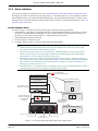
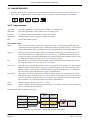
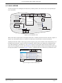
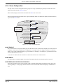
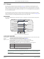
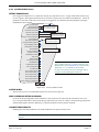
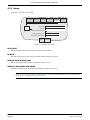
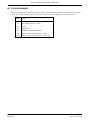
3.2 NAVIGATION KEYS
These keys allow the user to perform various context-related tasks such as to access the recorder configuration, to
archive data etc. In addition to this, left and right arrow keys or open/close folder keys appear where relevant.
Engineer
Close
folder
Left
cursor
Open
folder
Right
cursor
Root
3.2.1 Key functions
Close folder
Used, where appropriate, to recall the previous (higher level) display page.
Open folder
Used, where appropriate, to call a further (lower level) display page.
Left cursor
Used to navigate backwards through a text string, when editing.
Right cursor
Used to navigate forwards through a text string, when editing.
Root
Calls the 'Root Menu' as shown.
ROOT MENU KEYS
Home
Causes a return to the 'Home' page from any page in the recorder. As delivered, the 'Home' page is the
vertical trend display as depicted in figure 3, but this can be edited (in Operator/Config - Views) to be any
of the available display modes - Horizontal trend, Vertical bargraph, Horizontal bargraph, Numeric etc.
Operator
Causes the top level Operator page to appear. The appearance of this display is dictated by the security
level that the recorder is set to, and by the access level of the user. As despatched from the factory, the
recorder is in 'logged out' mode and the Operator page contains only the buttons labelled 'Archive', 'Security' and System. Further details appear in 'Access to configuration' below.
File
Allows the file system in that area of Flash memory that is accessible to the user, and the file system on
any floppy disk fitted to be viewed. See section 5 for details.
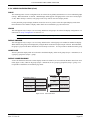
Goto View
Allows the user to select the display mode for the current group, as shown in figure 3.2.1, below. Display
modes not enabled for this group in Config/Views configuration pages do not appear. Goto View also
offers an alternative means of entry to the Alarm Summary page described in section 3.1.3, and also allows entry to the current group's Message Log pages, described below.
Goto Group
Allows group 1 or group 2 (if fitted) to be selected for display. If group 2 is not fitted, the Goto Group
menu does not appear. If either group is not 'display enabled' in the Config/Views page (section 4.3.4) it
is greyed. An alarm icon appears on the relevant group key if it containing one or more points in alarm.
The icon flashes if any of the group's alarms have not been acknowledged.
Login
Calls the login page described in section 3.3.1, below
Options
Used for a number of functions depending on the context. For example, entering or exiting Trend History
mode, or calling the filer option pop-up.
To quit the Root menu, touch the root key again.
Root menu
Goto View: Group 1
Home
Alarm Summary
Message Log
Vertical Trend
Horizontal Trend
Vertical Bargraph
Horizontal Bargraph
Operator
File
Goto Group
Goto View
Goto Group
Login
Options
Group 1
Numeric Page
Group 2
Figure 3.2.1 Root key menu and Goto View and Goto Group menus
User Guide
Page 18
HA027271
Issue 12 Mar 04
100 MM GRAPHICS RECORDER: USER GUIDE
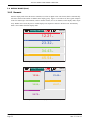
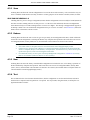
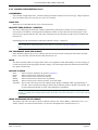
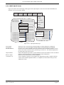
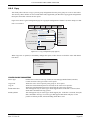
3.2.1 KEY FUNCTIONS (Cont.)
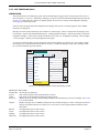
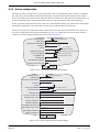
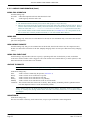
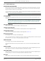
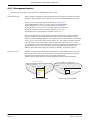
MESSAGE LOG
The Root menu/Goto View/Message log key calls the first Message Log page for the current group to the screen, as
shown in figure 3.2.1c, below. Alternatively, Message Log can be selected from the Alarm & Message options menu,
(section 3.1.3) and in this case, if there are multiple groups, the user selects a 'Group' for the Message Log display
from a pop-up (Goto Group) menu.
If there are more messages than can be displayed in the height of the screen, a scroll bar appears to allow 'hidden'
messages to be displayed.
Messages are retrieved from the history files in batches of 100 messages. If there are more than 100 messages, 'Earlier messages..' appears after the hundredth message. Touching 'Earlier messages..' calls the option menu, and touching 'Earlier messages..' in this menu, calls the next batch of 100, and so on. If applicable, operating 'Later messages..'
/ 'Later messages..' calls the previously displayed 100 messages.
As can be seen from the figure, the list of messages can be 'filtered' both by type and by time. For example, setting
the message type to 'Alarm' and the period filter to 'Last Day' excludes all messages except alarm messages which
have occurred within the previous 24 hours.
Engineer
Group Name
All Messages
13:36:25
28/01/04
All History
System
28/01/04 11:19:57 Maths Channel Failure
28/01/04 11:19:57
Alarms Power Up
28/01/04 10:55:36 Alarm(s) Ackd 2(1) 2(2)
Power Up
28/01/04 10:48:14 Alarm(s) off 2(1)
General Alarm(s) off 1(1)
28/01/04 10:39:03
28/01/04 10:20:16
BatchesEngineer,Overheat on turbine - system..
28/01/04 10:19:57 Alarm(s) on 1(1)
Logins
28/01/04 10:10:42 Alarm(s) on 2(1)
SigningsMaths Channel failure
28/01/04 09:09:12
28/01/04 11:19:57 Power Up
Audit Trail
All Messages
Figure 3.2.1c Message log page showing message-type picklist
MESSAGE TYPE FILTER
All Messages All messages are displayed
System
Only system messages and instrument alarms are listed.
Alarms
Only alarm on/off and acknowledgement messages appear.
Power Up
Displays power up messages only including Config revision and Security revision are included. See section
4.6.5 for more details.
General
Displays messages sent via Modbus, and operator notes/custom messages etc. If the e-mail option is fitted, a
mesage is generated each time an e-mail is sent. See section 11 of the options manual for details of the email option.
Batches
Not supported by this recorder version
Logins
Not supported by this recorder version
Signings
Not supported by this recorder version
Audit trail
Not supported by this recorder version
HA027271
Issue 12 Mar 04
User Guide
Page 19
100 MM GRAPHICS RECORDER: USER GUIDE
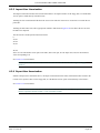
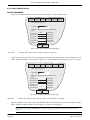
3.2.1 KEY FUNCTIONS (Cont.)
PERIOD FILTER
This picklist allows the user to select one of the following to define the period of time that the message list is to encompass:
All History, Last Month (28 days), Last Week, Last 3 Days, Last Day or Last Hour,
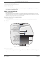
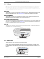
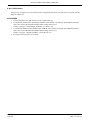
OPTION MENU
Touching a message (highlights yellow) calls the Option Menu* as shown in figure 3.2.1d, below.
Engineer
Group Name
All Messages
13:36:25
12/02/02
All History
Option
11/02/02 11:19:57 Maths
ChannelMenu
Failure
11/02/02 11:19:57 Power Up
Note
11/02/02 10:55:36 Alarm(s) Ackd 2(1) 2(2)
11/02/02 10:48:14 Alarm(s) off 2(1)
Enter History
11/02/02 10:39:03 Alarm(s) off 1(1)
11/02/02 10:20:16 Engineer,Overheat on turbine - system..
Full Details
11/02/02 10:19:57 Alarm(s) on 1(1)
11/02/02 10:10:42 Alarm(s) on 2(1)
Earlier messages..
11/02/02 09:09:12 Maths Channel failure
Earlier messages..
Figure 3.2.1d Message Log options menu
Note
Enter history
See section 3.5 of this manual
Operating the Enter History key causes the recorder to display that page of history which
includes the highlighted message. See section 3.4.1 for details of trend history. When in
Trend history mode, operating the Message Log key calls that message log page which
contains those messages which are nearest the trend history cursor time.
Full details
If the highlighted message is wider than the display, the whole message can be displayed by
operating the 'Full Details' key.
Refresh/Earlier messages../Later messages..
'Refresh' places (at the top of the screen), any messages, which have occurred since the
Message Log page was last entered, or since the last 'Refresh'. If earlier or later messages have
been selected, then 'Refresh' is replaced by 'Earlier messages..' or 'Later messages..' as appropriate, and operating the key calls the next or previously displayed group of 100 messages to
the display respectively.
* The option menu can also be called by touching the option key. In this case:
a. Enter History calls the current Trend History display, as described in section 3.4.1, and
b. Because no message is highlighted, the 'Full Details' key is not enabled,
Notes:
1 Selecting 'Enter History' whilst either 'Earlier Messages' or 'Later Messages' is highlighted calls the current History page.
2 If the Option Menu has 'timed out' leaving a message highlighted, and the option key is operated, then
this is equivalent to reselecting the message.
User Guide
Page 20
HA027271
Issue 12 Mar 04
100 MM GRAPHICS RECORDER: USER GUIDE
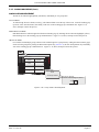
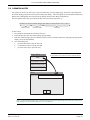
3.3 FIRST SWITCH-ON
When power is applied the recorder initialises, and once this process is complete, the home page is displayed. It is
unlikely that this will contain any useful information because the input channels will not, as yet, have been configured
to suit the type of input signals being applied to them, as described in section 4.
Notes:
1. There is no on-off switch associated with the recorder
2. Date, time and the message 'Power Up' are printed on the chart each time power is applied to the recorder, followed by date, time, Config Revision, Security Revision - see 'About' (section 4.6.5)
3. A red line is drawn across the width of the chart at power up.
The recorder has four security levels as follows
Logged out Initially, no access to recorder configuration is possible. Only Archive, Security/Login and the System
'About' functions can be accessed - via the root menu. Limited or full access can be permitted from
'Engineer' level.
Operator
No access to recorder configuration is possible until access permissions have been set up. Section
4.4.1, describes how limited or full access can be permitted by an operator with 'Engineer' level access.
Engineer
Accessed initially, by entering '10' as the password (section 3.3.1 below). Full access to all recorder
functions is available. Section 4.1.1 describes how the Engineer password can be edited and an Operator level password edited, if required. The section also describes how access permission to some or
all of the recorder functions can be granted, or not, to individual user names and default security levels
(except service).
Service
Full access to all recorder functions and to areas of recorder memory for diagnostic purposes. For use
only by Service Engineers.
HA027271
Issue 12 Mar 04
User Guide
Page 21
100 MM GRAPHICS RECORDER: USER GUIDE
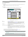
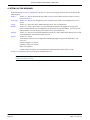
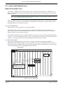
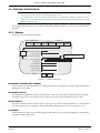
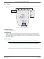
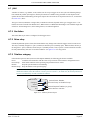
3.3.1 Access to Configuration
1
2
3
4
5
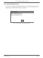
Once the recorder has initialised, touch the Root key, followed by 'Login'. Touching the 'Logged out' field in the
resulting display, calls the access level picklist as shown in figure 3.3.1a.
Press 'Engineer' to call the Password request page.
Touching the blank Password area calls the keyboard display (see figure 3.3.1b).
Touch <Numeric><1><0><OK> to enter the password '10'. The screen reverts to the 'Home' page.
Operation of the Root key followed by a touch on the Operator key calls the top level page allowing access to the
Archive, Save/Restore, Config, Security, Network*, and System areas described in section 4 below.
*Network configuration appears only if the Ethernet option is fitted.
Login
Select the required access level and enter the password if
required.
User Logged out
Logged out
Operator
Engineer
Service
Cancel
Figure 3.3.1a Access to configuration
Note: The figure above shows 'Login by user list'. If the Security Manager option is fitted, an alternative
procedure (Login by user ID) is possible. See section 4.4.2 (Management) for details.
User Guide
Page 22
HA027271
Issue 12 Mar 04
100 MM GRAPHICS RECORDER: USER GUIDE
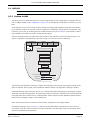
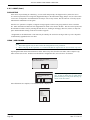
3.3.1 ACCESS TO CONFIGURATION (Cont.)
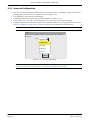
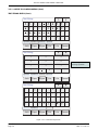
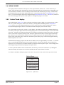
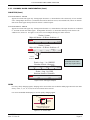
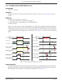
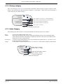
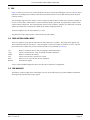
TEXT STRING ENTRY
The keyboard which appears when the password area is touched is the same as that which appears when any nonnumeric text string entry is required (e.g. channel descriptor). Figures 3.3.1b and 3.3.1c below are an attempt, within
the limitations of the illustrating process, to depict the available keyboards and thus the available character set. Actual
entry of the text string is by touching the relevant key. For items which require only a numeric entry (e.g. channel
range) the numeric keyboard appears.
When editing existing text strings, the existing text string appears highlighted, and will be replaced in its entirety by
the first character entered. To avoid this, the left arrow key can be touched to 'unhighlight' it.
Immediately below the keyboard are six keys with the functions listed below. When active, the background colour
changes to yellow for as long as the key is active.
Shift*
Once the shift key has been pressed, the next-entered letter appears as a capital; subsequent letters are in
lower case.
Caps* When pressed, all subsequent letters appear as capital letters until the Caps key is operated again
BSpc This backspace key deletes character to the left of the cursor.
Ovr
If selected, the next-entered character replaces (overwrites) the existing character to the right of the cursor
position. If not selected, the next-entered character in inserted into the existing text string at the cursor position.
Ok
Used to save the new text string and to return to the page from which the keyboard was called.
Cancel Causes a return to the page from which the keyboard was called without saving the new string.
*Note: The character on each display key is always a capital letter, whether or not the actual character being
entered is in capitals or lower case.
Cursor keys
Text string
(all * for password)
Tabs show
active keyboard
**
Q
W
E
R
T
Y
U
I
O
A
S
D
F
G
H
J
K
L
Z
X
C
V
B
N
M
\
.
Alphabet
Shift
Alphabet 2
Numeric
Caps
BSpc
P
Symbols
Ovr
Ok
Cancel
Backspace
Shift key
Caps Lock
Overprint
Figure 3.3.1b Alphabet 1 keyboard
HA027271
Issue 12 Mar 04
User Guide
Page 23
100 MM GRAPHICS RECORDER: USER GUIDE
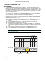
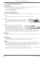
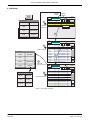
3.3.1 ACCESS TO CONFIGURATION (Cont.)
TEXT STRING ENTRY (Cont.)
Text String
a
ε
η
θ
Alphabet
µ
π
α
β
Γ
τ
φ
Ω
Σ
Alphabet 2
Numeric
Symbols
Caps
BSpce
Ovr
Shift
Ok
δ
Cancel
Text String
7
8
9
4
5
6
1
2
3
0
Alphabet
Shift
The 'E' key is used when
entering exponents
E
.
,
Ok
Cancel
Alphabet 2
Numeric
Symbols
Caps
BSpce
Ovr
$
%
^
&
*
(
)
Text String
!
"
-
_
+
=
{
}
[
]
:
;
@
'
~
#
<
>
,
.
?
/
|
'
3
Alphabet
Shift
2
Alphabet 2
Numeric
Symbols
Caps
BSpce
Ovr
Ok
Cancel
Figure 3.3.1c Alternative keyboards
User Guide
Page 24
HA027271
Issue 12 Mar 04
100 MM GRAPHICS RECORDER: USER GUIDE
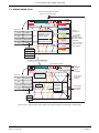
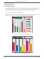
3.4 DISPLAY MODES
The display modes described below allow process values (input channels, totalisers etc. - known collectively as
points) for the current group to be displayed as vertical or horizontal 'chart' traces (Trend modes), as bargraphs (vertical or horizontal) or as numeric values. The display mode associated with the home page is Group 1, Vertical Trend
when dispatched, but any of the other display modes can be selected as the home page in Configuration/Views - section 4.3.4. The current display mode can be changed using the Root menu\Goto View key. The Home key returns the
user to the Home page from anywhere in the Operator or Configuration pages in the recorder.
3.4.1 Vertical Trend display
This (default) display (figure 3.4.1b) shows each point in the display group as though it were being traced on a white
chart. (It is possible to display on a black 'chart' instead, by selecting Dark Trend Background in Configuration/
Views). In either case, some thought should be given to trace colours selected in channel configuration. When selected, dark background applies both to vertical and horizontal trend display modes for both Groups.
One of the channels is said to be the 'current' or 'scale' channel. This channel is identified by its diamond shaped pen
icon and by its descriptor, digital value and scale being displayed on a 'current-channel faceplate' across the full width
of the chart. Faceplates for all the group channels can be displayed, by using the Faceplates On/Off key in the option
menu. If selected On, faceplates (showing colour, descriptor, digital value and units) for all the group's channels appear either above the current channel's faceplate (one or two points in group) or at the right hand edge of the screen
(three or more points in the group). If there are more than six points in the group, a scroll bar also appears allowing
hidden faceplates to be viewed.
Each channel in the display group becomes the 'current' channel, in turn, for approximately 10 seconds – i.e. the channels are cycled-through, starting with the lowest numbered channel. Once the final channel in the group has been
displayed for 10 seconds, the lowest numbered channel is returned to and the sequence repeats. This scrolling process
can be stopped using the Channel Cycling key in the Option menu.
To select a particular channel to be the current channel, the relevant pen icon can be touched. To cycle through the
channels manually, the faceplate area is touched repeatedly until the required channel is reached.
If a channel is included in the display group but its status is 'not good' for some reason, then its pen icon is hollow.
Option Menu
Note
Faceplates On/Off
Channel Cycling On
Enter History
Figure 3.4.1a Option menu
HA027271
Issue 12 Mar 04
User Guide
Page 25
100 MM GRAPHICS RECORDER: USER GUIDE
3.4.1 VERTICAL TREND DISPLAY (Cont.)
TIME CHANGE RECORDS
For vertical trend mode only, a line is drawn across the width of the chart whenever a time discontinuity in the record
occurs. These lines are volatile in real-time i.e. they disappear if the display mode is changed, or if a configuration
page is called etc.
Red line
A red line is drawn on the trend history chart at power up.
Blue line
A blue line indicates that recording has been disable/enabled in Group Configuration (section 4.3.2), or
by a recording job (section 4.7.9).
Green line
A green line appears if there has been a time change as a result of a clock job (section 4.7.6), an SNTP
synchronisation or by the operator physically changing the recorder time.
Note: Changes from standard time to daylight saving time and back again are not 'green lined' in this way
TREND HISTORY
Trend history, allows the user to view the history of the display group. The maximum amount that can be recalled
depends on a number of factors, including how many points are configured, how rapidly the traces are changing and
so on. At a recording rate of 20mm/hour (see group configuration - section 4.3.2), with all channels configured, a
minimum of 30 day's worth of traces is available for viewing, provided that the group contents are not re-configured
during this period (in which case, the history starts at the end of the re-configuration). The amount of trace visible on
the screen depends on the recording rate - the higher the rate, the less trace is visible at any one time.
Notes
1 Trend history is not available for groups with 'Recording Enable' disabled (Group configuration - section
4.3.2).
2 Channel cycling is inhibited in Trend History Mode. To increment the current channel, touch the
faceplate.
3 Group faceplates are not displayed in History Mode.
4. With A/B switching selected, traces are displayed with the 'A' or 'B' span/zone, colour settings etc. obtaining at the cursor time. See sections 4.3.2, 4.3.3 and 4.7 for more details of A/B switching.
To enter Trend History, the Root Menu Options key can be used (as shown in figure 3.4.1), or the trace area of the
screen can be continuously touched until the screen blanks prior to re-drawing. A 'Preparing History, please wait' message appears whilst the re-drawing calculation is taking place. Although tracing stops whilst trend history mode is
active, no data is lost - Process Variable values are still saved in the recorder memory and alarms are still scanned-for
and any associated action taken.
The History display is similar to the real-time trend display, with the addition of a slider control and up and down
keys for selecting that part of trend history which is to be displayed. The controls are used as follows:
1 Touching the up/down key causes the record to move an incremental amount.
2 Holding the up/down key continuously, causes continuous movement.
3 Touching the bar above or below the slider causes a page-height shift.
4 Touching and dragging the slider, whilst observing the time/date display, allows the user to select the section of
history exactly.
On first entry to the History mode, the channel value and the time and date shown in the faceplate are those at the top
edge of the chart. Touching the screen causes a cursor to appear at point of screen contact. This cursor can be
touched and dragged up and down the screen to provide a reference point on the current trace. The displayed value
date and time refer to the cursor intersection with the current channel. To return to real-time trending, the Options key
in the root menu is operated, followed by 'Exit History'.
User Guide
Page 26
HA027271
Issue 12 Mar 04
100 MM GRAPHICS RECORDER: USER GUIDE
3.4 DISPLAY MODES (Cont.)
Entry to trend mode from Home
key or by cycling screens.
Engineer
99%
Channel 1
61.59 C
0.0000
Channel 1
61.59
100.00
C
Channel 2
Root menu
Home
13:39:12
06/12/01
Group Name
Operator
File
Goto View
Goto Group
Login
Options
Current channel
faceplate; Touch/
release to increment channel
68.82
13:31:02
06/12/01
C
Channel 3
OFF C
Channel 4
Touch pen icon to
select that channel
06/12/01 13:21:02 Alarm(s) off 2 (1)
56.57 C
06/12/01 13:19:04 Alarm(s) on 2 (1)
Channel 5
13:17:42
06/12/01
Option Menu
15.66 C
Group
faceplates
1 or 2 points faceplates
appear above
current channel
faceplate.
For more than 6
points, a scroll
bar appears
Channel 6
Note
41.35 C
Faceplates On/Off
Channel Cycling On
Enter History
Preparing History, please wait
Trend history mode
Engineer
13:39:12
06/12/01
Real
time/date
13:29:38 06/12/01
Cursor
time/date
Group Name
99%
Channel 1
65.55 C
0.0000
Value at cursor
time/date
Root menu
Home
100.00
Press bar to
move one
pageful
Operator
13:31:02
06/12/01
File
Goto View
Login
Goto Group
Cursor
06/12/01 13:21:02 Alarm(s) off 2 (1)
Options
06/12/01 13:19:04 Alarm(s) on 2 (1)
Press
arrow keys
to move
minimum
amount
Move slider
to required
date/time
13:17:42
06/12/01
Option Menu
Note
Exit History
Figure 3.4.1b Typical Vertical Trend display (faceplates enabled) and trend history mode display
HA027271
Issue 12 Mar 04
User Guide
Page 27
100 MM GRAPHICS RECORDER: USER GUIDE
3.4 DISPLAY MODES (Cont.)
3.4.2 Horizontal Trend display
This display (figure 3.4.2a) is similar to the Vertical Trend display described above, except that the traces are produced horizontally rather than vertically.
Engineer
12:03:27
29/01/04
Group Name
Channel 1
21.2613 ˚C
35.00
Faceplates for current
channel.
Touch either faceplate to
increment channel
(or touch pen to select
channel).
Current pen icon
Bargraph
Alarm threshold
Time at
adjacent
gridline
Non-current
pen icon
12:00:52
29/01/04
12:02:12
29/01/04
0.000
29/01/04 12:02:20 Alarm(s) off 2 (1)
Message bar
Latest message
If this arrow is displayed, then
touching the message bar displays
previous messages
Figure 3.4.2a Horizontal trend display mode
One of the channels is said to be the 'current' or 'scale' channel. This channel is identified by its pen icon being diamond shaped rather than triangular as for non-current channels. If a channel is included in the display group but its
status is 'not good' for some reason, then its pen icon is hollow. Each channel in the display group becomes the 'current' channel, in turn, for approximately 10 seconds – i.e. the channels are cycled-through, starting with the lowest
numbered channel. Once the final channel in the group has been displayed for 10 seconds, the lowest numbered channel is returned to and the sequence repeats. This scrolling process can be stopped using the Channel Cycling key in
the Option menu.
As well as the normal faceplate above the 'chart', showing the current channel's descriptor and its digital value, a
bargraph representation of the current channel's value together with a scale showing the low and high range values for
the channel appears to the right of the chart. Touching the faceplate or the bargraph* causes the current channel
number to increment. To select a particular channel to be the current channel, the relevant pen icon can be touched. In
either case, the bargraph and the background colour of the channel descriptor takes the colour of the current channel.
Time and date are printed on the 'chart' immediately to the right of alternate vertical grid lines, and it is these grid
lines to which the printed time relates.
There is no horizontal trace Trend History function - touching the 'chart' for a few seconds (or using the Root menu
Options key, then 'Enter History') calls the vertical trend history page described in section 3.4.1, above.
*Note: For 'zoned' points (section 4.3.3), the bargraph must be touched within the scale area to increment the
channel.
User Guide
Page 28
HA027271
Issue 12 Mar 04
100 MM GRAPHICS RECORDER: USER GUIDE
3.4.2 HORIZONTAL TREND MODE (Cont.)
Below the 'chart', is a message bar, containing the latest message. If there is more than one message, an arrow head
icon appears near the right hand end of this message bar, and if this appears, then touching the message bar calls a
pop-up box (figure 3.4.2b) in which all relevant messages are displayed.
View Messages
29/01/04
29/01/04
29/01/04
29/01/04
12:02:20
12:00:22
11:16:04
10:28:49
Alarm(s)
Alarm(s)
Alarm(s)
Alarm(s)
off
on
0ff
on
2
2
1
1
(1)
(1)
(1)
(1)
Ok
Figure 3.4.2b Horizontal trend mode message dialogue box
HA027271
Issue 12 Mar 04
User Guide
Page 29
100 MM GRAPHICS RECORDER: USER GUIDE
3.4 DISPLAY MODES (Cont.)
3.4.3 Vertical bargraph
This display mode shows the Process Variable (PV) values as vertical bars. Faceplates containing digital values and
alarm data appear above the bars for one or two points, or at the right hand side of the screen (as shown below) for
three or more points. Faceplates can be switched on and off from the Root menu/Options menu display.
Trend History mode is not available from this display mode.
Operation of the Root menu Options key calls the Option menu display for this display page, allowing faceplates to be
selected on or off. This feature is available for vertical trend and vertical bargraph displays only.
Engineer
09:32:45
29/01/04
Group Name
100.0 100.0 100.0 100.0 100.0 100.0 Channel 1
65.91 ˚C
Channel 2
48.09 ˚C
Channel 3
41.87 ˚C
Channel 4
40.48 ˚C
Channel 5
83.73 ˚C
0.00
0.00
0.00
0.00
0.00
Channel 6
18.86 ˚C
0.00
Figure 3.4.3a Vertical bargraph display (with faceplates)
Engineer
09:36:42
29/01/04
Group Name
100.00 100.0000 100.0000 100.0000 100.0000 100.0000
0.00
0.0000
0.0000
0.0000
0.0000
0.0000
Figure 3.4.3b Vertical bargraph display (faceplates off)
User Guide
Page 30
HA027271
Issue 12 Mar 04
100 MM GRAPHICS RECORDER: USER GUIDE
3.4.4 Horizontal bargraph
This display mode shows the Process Variable (PV) values as horizontal bars with digital values and alarm data displayed, as shown in figure 3.4.4. Trend History mode is not available from this display mode.
Engineer
10:39:38
29/01/04
Group Name
Channel 1
14.59 ˚C
0.00
Channel 2
100.00
36.0256 ˚C
0.0000
Channel 3
100.0000
38.3237 ˚C
0.0000
Channel 4
100.0000
69.9240 ˚C
0.0000
Channel 5
100.0000
32.0654 ˚C
0.0000
Channel 6
100.0000
88.2337 ˚C
0.0000
100.0000
Figure 3.4.4 Horizontal bargraph display
HA027271
Issue 12 Mar 04
User Guide
Page 31
100 MM GRAPHICS RECORDER: USER GUIDE
3.4 DISPLAY MODES (Cont.)
3.4.5 Numeric
Numeric display mode shows the Process Variable (PV) values as digital values. The format (which is automatically
selected) is based on the number of channels in the display group. Figures 3.4.5a and 3.4.5b, show typical examples
of the one column (up to four channels) and two column versions (five or six channels) of this display mode, respectively. Within each version, the process variable display areas expand or contract to fill the screen. Trend History
mode is not available from this display mode.
.
Group Name
Engineer
99%
11:19:30
02/01/01
Channel 1
12.21
C
23.32
C
34.43
C
45.54
C
Channel 2
Channel 3
Channel 4
Figure 3.4.5a Numeric display mode (1 to 4 channels)
Engineer
Group Name
Channel 1
99%
11:00:24
02/01/01
Channel 2
12.34
C
Channel 3
23.45
C
45.67
C
Channel 4
34.56
C
56.78
C
Channel 5
Figure 3.4.5b Numeric display mode (5 or 6 channels)
User Guide
Page 32
HA027271
Issue 12 Mar 04
100 MM GRAPHICS RECORDER: USER GUIDE
3.5 OPERATOR NOTES
It is possible for the user to enter a note, of up to 60 characters, from any display page. Each note is associated with
the current display group and becomes a part of that group's history. The notes appear on vertical and horizontal trend
displays only, although they can be entered in any display mode (but not during configuration).
The note appears on the chart, preceded by the date, time and current login name e.g.
12/09/01 10:32:43 Frederick Bloggs, New Spray nozzles fitted to Line A, Tube 1.
Date and time
Full User Name
Message
To enter a note:
1. Press the Root menu Option key, then the 'Note' key
2. Touch the Operator Note area of the resulting pop-up display.
3. Enter the required string of up to 60 characters (spaces are also counted as characters) using the pop-up keyboard
display. Press Ok when finished.
4. View the message and
a
press the Ok button to enter the note OR
b
re-touch the text area to edit the note OR
c
press the Cancel key to quit note entry.
*Note: The option menu is context sensitive, so
its appearance may differ from the example shown
Option Menu
Note
Faceplates On/Off
Channel Cycling On
Enter History
Note
Operator Note
Ok
Cancel
Figure 3.5 Access to note entry page
Note: Operator Notes should not be confused with similar messages, appearing as the result of a 'Job' action.
Such messages are described in Section 4.3.7 of this manual.
HA027271
Issue 12 Mar 04
User Guide
Page 33
100 MM GRAPHICS RECORDER: USER GUIDE
4 SETTING UP THE RECORDER
As described in the 'Access to Configuration' (section 3.3.1) above, the setting-up of the recorder is divided into the
following areas:
Archive
Section 4.1 - Allows manual archiving of data to disk or (if the Ethernet option is fitted) to a remote
host (FTP transfer).
Save/restore Section 4.2 - Allows new configurations to be created and saved, and saved configurations to be 'restored'.
Config
Section 4.3 - This is the major channel/alarm/option etc. area of configuration.
Security
Section 4.4 - Allows passwords to be entered and edited and allows the Engineer-level password
holder to enable/disable areas of configuration to Operator-level password holders. New users can be
added, with their own user names, passwords and access level permissions.
Network
Section 4.5 - This area sets up the IP address/host names etc. used in FTP transfer, Remote Viewer and
SNTP applications (if the Ethernet option is fitted).
System
Section 4.6 - Allows:
Time and date functions to be set and edited (including daylight saving start and finish dates, time
zones etc.)
Display language to be chosen
Option key codes to be entered
Inputs to be adjusted.
System contains an 'About' screen describing the software/hardware status of the recorder.
Section 4.7 describes the various job categories available to the user
Note: In all the following descriptions, if a change is made to a menu item, then the item text changes from
black to red, until it is 'saved'.
User Guide
Page 34
HA027271
Issue 12 Mar 04
100 MM GRAPHICS RECORDER: USER GUIDE
4.1 ARCHIVE
Note: The archiving functions described below can also be initiated by job action - see section 4.7.12
4.1.1 Archive to disk
This allows the user to initiate data transfer, to a mass storage medium such as a floppy disk, for all groups with 'Archive to Media' enabled (Group configuration - section 4.3.2), by touching the relevant archive period key (e.g. Last
Day').
Archiving starts as soon as the selection is made, and cannot be stopped until completed, unless the Cancel Archive
key is operated, in which case the archive will be stopped after a confirmatory message has been responded to. The
Cancel key is active only if 'Archiving Control' is enabled in Security/Access (section 4.4 of this manual). If archiving is enabled for more than one group, a warning message appears.
Selection of 'Bring Archive Up To Date' causes the recorder to select whichever of the Last Hour/Last Day etc. categories is appropriate to bring the archive up to date. Figure 4.4.1 shows the archive to disk menu.
Archive
Save/R.. Config Security Network System
Disk
Last Archive 12/06/2003 11:32:18
Remote
Bring Archive Up To Date
Section 4.1.2
Archive Last Hour
Archive Last Day
Archive Last 7 Days
Archive Last 31 Days
Archive All
Suspend Archiving
Cancel Archive
Archive Transfer Inactive
Media Size 1458688
Bytes
Free Space 14848
Bytes
Figure 4.1.1 Disk archive strategy configuration
If the disk becomes full before archiving is complete, archiving pauses and a pop-up request appears, asking for the
disk to be replaced. If this request is not responded-to within 10 minutes of its appearance, archiving is aborted,
Unattended archiving can be paused by the user (e.g. to change disks without losing data) by operating the 'Suspend
Archiving' / 'Resume Archiving' button. Any archiving in progress is allowed to complete before the 'Suspend Archiving' request takes effect. Transfer activity is indicated in the 'Archive transfer' window. Should the disk become full,
the user will be prompted to replace it with a different one.
Below the selection buttons are a number of status windows relating to the mass storage medium.
If automatic archiving is active (section 4.3.5), then this and the manual archive will operate on a first come-first
served basis. Some files will be saved twice in such a circumstance, the later archive's files overwriting any earlier
archive's files which have the same name.
HA027271
Issue 12 Mar 04
User Guide
Page 35
100 MM GRAPHICS RECORDER: USER GUIDE
4.1.2 Remote archiving (FTP transfer)
This allows archiving of recorder files, for all groups with 'Archive via FTP' enabled, to a remote computer, connected
(using the RJ45 telephone type connector at the rear of the recorder) either directly, or via a network . 'Archive via
FTP' is enabled/disabled as part of (Group configuration - section 4.3.2)
In order to carry out a successful transfer, details of the remote host must be entered in the Archive section of the
'Config' menu (section 4.3.5).
Note: An FTP server must be running on the remote host.
Figure 4.1.2 shows the archive menu for remote archiving. The Archive last hour/day etc. keys allow the user to determine which files are to be archived. Selection of 'Bring Archive Up To Date' causes the recorder to select whichever of the Last Hour/Last Day etc. categories is appropriate in order to bring the archive up to date. The 'Last
Archive' window shows the time and date of the previous archive. The Archive Transfer window shows archive status
as 'Active' or 'Inactive'.
Archive
Disk
Save/R.. Config Security Network System
Last Archive 01/01/1970 00:00:00
Remote
Bring Archive Up To Date
Section 4.1.1
Archive Last Hour
Archive Last Day
Archive Last 7 Days
Archive Last 31 days
Archive All
Cancel Archive
Archive Transfer Inactive
Figure 4.1.2 Remote archive strategy configuration
Additionally, a user on a remote PC has full viewing capabilities, can extract recorder files at any time, and can access
those items of recorder configuration that are associated with the user's login. For successful connection, 'Connect
from Remote' must be enabled and the 'Remote user name' and 'Remote password' must be defined in one of the accounts (all in the Security access menu (section 4.4.1)).
Notes:
1. In order to view history files when accessing the instrument remotely, the recorder's address, the 'Remote
user name' and the 'Remote password' must be supplied to an FTP client such as PC Review or
Microsoft® Internet Explorer.
2. When accessing files using Microsoft® Internet Explorer, the address (URL) field can be in one of two
forms:
a ftp://<instrument IP address>. This allows the user to log in as the anonymous user (if the instrument has any account with 'Remote user name' set to 'Anonymous' and a blank password).
b ftp://<user name>:<password>@<instrument IP address> to log in as a specific user.
3. For IE5 users only: Microsoft® Internet Explorer displays, by default, history files only. To exit the
history folder, either uncheck the Tools/Internet Options/Advanced/Browsing/"Enable folder view for
FTP sites" option, or check the Tools/Internet Options/Advanced/Browsing/"Use Web based FTP" option.
User Guide
Page 36
HA027271
Issue 12 Mar 04
100 MM GRAPHICS RECORDER: USER GUIDE
4.2 SAVE / RESTORE
As shown in figure 4.2a, touching the Save/Restore key calls the picklist: Save, Restore, New, Text, Import/Export
user Linearisation.
Archive Save/R.. Config Security Network System
Configuration Data
Security Data
Save
Network Data
Restore
Screen Data
Save for pre Version 1.8
File Name
Save
New
New/Default
Text
Import User Linearisation
Configuration Data
Export User Linearisation
File Name
Security Data
Network Data
Save As Text
Screen Data
Restore
User Linearisation
File Name
1) UserLin1
File Name
userlin
Import
Export
Figure 4.2a Save/Restore menu
Where a file name is required, then, if the displayed file name is suitable, operation of the 'Save', 'Restore', 'Import' or
'Export' key will initiate the action. If, instead, a file name has to be entered, this is carried out as follows:
Touching the file name window causes a pop-up menu to appear, giving a list of 'Volumes' in the Flash memory or on
the floppy disk (if inserted). Figure 4.2b shows an imaginary Volume contents list, displayed by touching the name
'user', then operating the 'open folder' key. (See section 5, below for more details). Once the correct folder is open,
either select an existing file, or enter a new file name, by touching the FileName window and entering the name using
the pop-up keyboard(s) as described in section 3.3.1 above. Operation of the Save or Restore key initiates the action.
\user\
Hide
Name
Type
Date
cal\
Folder
03/06/00 12:35:08
config\
01/05/00 10:27:13
Filter1a
Folder
Config
lib\
Folder
05/07/00 10:23:14
sdb\
Folder
11/05/00 14:01:08
FileName: Filter1b
Bytes
05/07/00 10:22:23
4445
Save
Cancel
Figure 4.2b Typical volume contents page
HA027271
Issue 12 Mar 04
User Guide
Page 37
100 MM GRAPHICS RECORDER: USER GUIDE
4.2.1 Save
Touching this item allows the current configuration to be saved in the recorder's memory. Files saved in this way are
not in a 'readable' format and are used only for archive /security purposes or for transfer to another, similar, recorder.
SAVE FOR PRE VERSION 1.8
Checking this box, prior to saving a configuration, means that the configuration can successfully be loaded (Restored)
into other recorders running software versions prior to 1.8. If the box is left unchecked, then Saved configurations
can be Restored only to recorders running software versions 1.8 or higher. The message 'Unsupported File' appears if
an attempt is made to save an 'Unchecked' configuration into a pre version 1.8 recorder. See Section 4.6.5 (About) for
details of how to determine software version.
4.2.2 Restore
Touching this item allows the user to select or type-in a previously saved configuration file name, which will then be
used as the current configuration. Touching the 'Restore' key completes the operation. Tick boxes allow one or more
of Configuration Data, Security Data (note 3), Network Data or Screen Data to be chosen to be restored.
Notes
1 Screen data relates to faceplate status for vertical trend and vertical bargraph display modes.
2. If archiving is in progress when a 'Restore' is requested, the Restore operation will be delayed until the
archive is complete (maybe several minutes). If required, the 'Cancel Archive' key can be used to speed
up the restore process, at the cost of losing the archive data.
3. If 'Centralised Security' is active (part of Security Management configuration - section 4.4.2) 'Security
Data' is not selectable (either for 'Restore' or 'New' (below)).
4.2.3 New
Touching this item causes the factory entered default configuration to be loaded for use, or for editing. Operation of
the New/Default key completes the operation. Tick boxes allow one or more of Configuration Data, Security Data
(note 3, above), Network Data or Screen Data to be chosen to be restored. (Screen Data relates to faceplate status for
vertical trend and vertical bargraph display modes.)
4.2.4 Text
This is identical to the 'Save' function described above, but the configuration is saved in ASCII format, and can be
transferred to a computer and read, printed etc. as required. It is not possible, using this means, to modify the configuration and then re-load it.
User Guide
Page 38
HA027271
Issue 12 Mar 04
100 MM GRAPHICS RECORDER: USER GUIDE
4.2.5 Import User Linearisation
The Import Linearisation feature allows linearisation tables to be imported either via the floppy disk, or if the Remote
Viewer option is fitted,directly from the host PC.
Touching the User Linearisation field allows the user to select which of 'UserLin1' to 'UserLin4' is to contain the imported file.
Touching the File Name field, calls a popup menu similar to that shown in figure 4.2b. This allows the user to select
the table to be imported.
The file must be comma separated ASCII as follows:
n,
X1,Y1
X2.Y2
X3,Y3
.
.
Xn,Yn
where 'n' is the total number of XY pairs in the table, and or each pair, X is the input value, and Y is the linearised
value corresponding to X.
See section 4.3.8 for full details.
Note: Imported linearisation tables will not become effective until after the next configuration 'Apply'
operation
4.2.6 Export User Linearisation
Similar to 'Import user Linearisation, above, the Export Linearisation feature allows linearisation tables created in the
recorder to be exported either via the floppy disk, or if the Remote Viewer option is fitted,directly to the host PC.
See section 4.3.8 for full details.
Note: If an exported linearisation table is to be used in a recorder with software version prior to version 2.2, it
must be exported in Numeric format (i.e. not in Scientific format).
HA027271
Issue 12 Mar 04
User Guide
Page 39
100 MM GRAPHICS RECORDER: USER GUIDE
4.3 CONFIGURATION
Touching this key calls the top level configuration pick list: Instrument, Groups, Channels, Views, Archive, Events,
Messages, etc. as shown in the overview figure (figure 4.3).
When making changes to the configuration the name of each changed parameter is displayed in red (instead of the
normal black) until the 'Apply/Discard' key has been operated. For example, in channel configuration, if a thermocouple were to be changed from Type J to Type K, 'Lin Type' would appear in red, until the Apply key was operated.
Should an attempt be made to leave configuration with unsaved changes, a warning message appears, allowing the
user to apply the changes, to discard the changes or to return to configuration (Cancel).
Config
Data has been modified
Apply
User Guide
Page 40
Discard
Cancel
HA027271
Issue 12 Mar 04
HA027271
Issue 12 Mar 04
V
V
0
1
0
Select: None, Linear or Log
(Log available only if Log Scales option fitted)
Select Job
action
Select: alarm number
Select: Off,
Unlatched,
Latched,
Trigger
Select Numeric or
Scientific
Discard
No Action
1
Off
1
26
4
Numeric
%
%
0
100
V
V
0
Config\Views
(Section 4.3.4)
See sheet 2 for
further items
Views
Channels
Groups
Instrument
0
Discard
Horizontal Bargraph
1) Group 1
Group
1) Group 1
Choose the
Home display
mode for the
selected group
or for instrument
Apply
Etc.
Select Group
Days
25.96
Discard
List of all available points
(input channels, maths
channels, totalisers etc.).
= Enabled
mm/hr
s
1,200
Appear only if
'Recording Enable'
is enabled.
Field(s) vary with selected
Grid Type
Select None. Linear, Log (if
option fitted) or 'From Point'.
1
Channel 1
From Point
mm/hr
s
1,200
Select mm/hr or in/hr
1
Group 1
mm/hr
1) Group 1
Apply Discard
Preset Hour 12
Preset Minute 0
Group Number
Trend Units
Descriptor
A/B switching
Trend Speed
Trend Interval
Grid Type
from
Recording Enable
Recording Speed
Recording Interval
Trend History Duration
Archive to Media Enable
Select group for
Home display
Archive via FTP Enable
Alarm Message
Ack Message
Select Instrument or group
TurbineTempA
Select group for display
TurbineTempB
mode enable
TurbineTempC
Config\Groups
(Section 4.3.2)
Figure 4.3 Configuration menu overview (sheet 1)
Apply
Home Time-out
Home Group
Dark Trend background
Dark History Background
Scope
Group
These fields appear
only if Scope = 'Group'
Display Enabled
Home Page
Vertical Trend
Horizontal Trend
Vertical Bargraph
Horizontal Bargraph
Numeric Page
Select: Off, Internal, External or Remote
Select: None, High or Low
1
TurbineTempA
Off
None
1
These fields vary with the
selected Scale Type.
Select: None,
None
2, 4, 8, 16, 32, 64, 128 or 256
5
Linear
V
Select: Celsius, Fahrenheit,
Kelvins or Rankine
C
V
C
C
0
Select Linearisation
type (e.g.Type K)
Off, T/C, mV,V, mA,
RTD, Ohms, Digital,
Comms or Test
1
Type K
Select channel
number
Unadjusted
Thermocouple
5.003
1) TurbineTempA
Apply
Max Decimal Digits
Colour
Alarm Number
Enable
Job Number
Category
Channel Number
Value
Input Type
Lin Type
Range Low
Range High
Range Units
Scaled
Scale Low
Scale High
Units
Offset
Scale Type
Scale Divisions - Major
Scale Divisions - Minor
Filter
Break Response
Cold Junction Type
Descriptor
A/B switching
Spanned
Span Low
Span High
Zone Low
Zone High
PV Format
Config\Channels (Section 4.3.3)
Instrument Name Instrument
Normal Display 100 %
Saver Display 50
%
Config\Instrument
Save After 1 Minutes
(Section 4.3.1)
Modbus Address 1
Modbus Security Disabled
= Disabled
Comms Channel Timeout 0
s
Archive Save/R.. Config Security Network System
100 MM GRAPHICS RECORDER: USER GUIDE
4.3 CONFIGURATION (Cont.)
User Guide
Page 41
User Guide
Page 42
Discard
Config\Messages
(Section 4.3.7)
Primary remote host 0.0.0.0
Primary login name a n o n y m o u s
Maths 6
Alarms Per 4
Groups 2
(currently 0)
Autoconfigure
Relays on board 1 1
Discard
(currently 0)
Relay Boards 1
Archive CSV Enabled
Email 12
Logarithmic Scales Enabled
User linearisations 4
Messages 12
Modbus/TCP Clients 2
File Transfer Protocol 4
Remote Viewers 4
Remote Viewer Level Full
Select Numeric or
Scientific
Apply
Discard
Replace {2} with Source Value
Replace {3} with Specified Descriptor
{3} source Totaliser 1
Replace {4} with Specified Value
{4} source Totaliser 1
Replace {5} with Blank
Replace {6} with Blank
Replace {1} with Source Descriptor
Days
Appears only if CSV option fitted
Select archive interval
Days
Mb
Discard
Select:
Point whose descriptor, value etc. is to be
inserted
Select embedding
source
Select Message 1 to 12
Message Number 1) The value of {..
for configuration
Message The value of {1} = {2} & {3} = {4}
Figure 4.3 Configuration menu overview (sheet 2)
Apply Discard
X2 1
Y2 1
Y1 0
X1 0
Number of Points
2
Format Numeric
Descriptor
User Linearisation 3) UserLin3
Apply
Retype password * * * * *
Secondary password * * * * *
Secondary remote host 0.0.0.0
Secondary login name a n o n y m o u s
Select: Overwrite or Stop
Mb
Select: Normal or High
Remote path / r e c o r d e r / G r o u p 1
Ftp File format Binary
Select 'Disk' or
'Remote' settings
Select: Hourly, Daily, Weekly,
Monthly or Automatic
Days
Mb
Select: Normal or High
Discard
%
Show Remote settings
Archive to Remote None
Retype password * * * * *
Config\User Linearisations
(Section 4.3.8)
Apply
Compression Normal
Apply
Flash Size 2 . 7 5
Shortest Trend History G r o u p 1
Duration 8 . 7 1
Remote
Media Full event limit 100
Disk Archive Capacity 3 . 5 7
Media Size 1.38
On Media Full Overwrite
Archive to Media None
Primary password * * * * *
Security Manager Enabled
Apply
Select source inversion or not
Make sub-sub selection (if any)
Make source 2 sub selection (if any)
Select source 2
Source 2 Sense
Descriptor Event 1
Select: 1 or 2
Job Number 1
Category No Action
Select Job Category
Operator
Select source 1
Make source 1 sub selection (if any)
Select 1 to 6
Select logic combination: Only, AND,
And
OR, NAND, NOR, XOR.
Select source inversion or not
Not Source 2
Source 1 Sense Source 1
Alarm 2
Source 2 Point Alarm
On Math 12
Event Number 1) Event 1
Source 1 Alarm on Group
On Group 1) Group 1
Disk
Timers 6
Options
Emails
Timers
Counters
Totalisers
Maths
User Linearisations
Config\Events (Section 4.3.6)
Config\Archive
(Section 4.3.5)
Flash Size 2 . 7 5
Shortest Trend History G r o u p 1
Duration 7 . 2 8
Show Disk settings
Compression Normal
Counters 6
Totalisers 6
Events 6
Fitted channels 6
Config\Options
(Section 4.3.9)
Maths......... Options section 3
Totalisers... Options section 4
Counters.... Options section 5
Timers........ Options section 6
Emails...... Options section 11
Software options
Messages
Events
Archive
For previous items
see sheet 1
Archive Save/R.. Config Security Network System
100 MM GRAPHICS RECORDER: USER GUIDE
4.3 CONFIGURATION (Cont.)
HA027271
Issue 12 Mar 04
100 MM GRAPHICS RECORDER: USER GUIDE
4.3.1 Instrument configuration
Instrument Name Instrument
Normal Display 100 %
Saver Display 50
%
Save After 1 Minutes
Modbus Address 1
Modbus Security Disabled
= Disabled
Comms Channel Timeout 0
s
Preset Hour 12
Preset Minute 0
Apply Discard
Figure 4.3.1 Instrument Configuration menu
INSTRUMENT NAME
Allows the entry of an alphanumeric name for the recorder, up to 20 characters long. See section 3.3.1 for text entry
techniques.
NORMAL/SAVER DISPLAY
Allows normal and 'saver' display brightnesses to be defined. Defaults are Normal = 100%; Saver = 50%.
SAVE AFTER
The number of minutes (between 1 and 99 inclusive), which are to elapse after a screen operation, before the screen
brightness changes from 'normal' to 'saver'. Default is one minute.
MODBUS ADDRESS
Allows a Modbus address of between 1 and 247 to be set up for the unit when it is acting as a Modbus slave.
MODBUS SECURITY DISABLED
When using MODBUS, it is possible, by 'checking' this field to allow a host computer to access the recorder without
its first having to supply a valid User name and Password. This box must be checked if this unit is acting as a Modbus
slave in order for the unit to be detected. Once communications have been established, Modbus security can be enabled, providing that the Slave's Remote user name and password have been entered at the Master. See also section
2.2.4 of the Communications Manual.
COMMS CHANNEL TIMEOUT
Allows a number of seconds (between 1 and 999) to be entered. If none of the channels set to 'Comms' is communicated with, within this period, an event source (Comms channel timeout) is set, and remains set until the next communication. An entry of 0 disables the time out.
PRESET HOUR
Enter an hours number between 0 and 23 for use with Clock Job - Preset clock.
PRESET MINUTE
Enter a minutes number between 0 and 59 for use with Clock Job - Preset clock.
Note: See section 4.7 for a description of recorder jobs, and section 4.5.1 for further details of time synchronisation.
HA027271
Issue 12 Mar 04
User Guide
Page 43
100 MM GRAPHICS RECORDER: USER GUIDE
4.3.2 Group configuration
Note: Group 1 is a standard recorder feature. Group 2 is an optional extra
This section allows the user to define, for each group, the following:
a Group trend speed/interval
b Group recording speed/interval
c Group descriptor
d Group content
e Chart grid divisions
The production of alarm messages and the saving of group data to Flash memory, to removable mass storage medium
(e.g. floppy disk) and/or to remote computer (FTP transfer) can also be enabled / disabled from this menu.
Group Number 1) Group 1
Trend Units mm/hr
Descriptor Group 1
A/B Switching
Trend Speed
Trend Interval
Grid Type
from
Recording Enable
Recording Speed
Recording Interval
Trend History Duration
Archive to Media Enable
Archive via FTP Enable
Alarm Message
Ack Message
TurbineTempA
TurbineTempB
TurbineTempC
Select Group
Select mm/hr or in/hr
1,200
mm/hr
1
s
Select None. Linear, Log (if
option fitted) or 'From Point'.
From Point
Channel 1
Field(s) vary with selected
Grid Type
1,200
mm/hr
1
s
25.96
Days
Appear only if
'Recording Enable'
is enabled.
= Enabled
List of all available points
(input channels, maths
channels, totalisers etc.).
Etc.
Apply
Discard
Figure 4.3.2a Group configuration menu
GROUP NUMBER
Allows group 1 or group 2 (if fitted) to be selected for configuration
TREND UNITS
Allows mm/hr or inches/hour to be selected for the 'chart' speed. Automatically converts the trend speed field below.
DESCRIPTOR
Allows the group name to be edited. See section 3.3.1 for text entry techniques.
A/B SWITCHING
If enabled, this function allows alternative values for Trend speed/interval and Recording speed/interval to be entered.
'A' values are used during normal operation. 'B' values are switched to by job action, as described in section 4.7
User Guide
Page 44
HA027271
Issue 12 Mar 04
100 MM GRAPHICS RECORDER: USER GUIDE
4.3.2 GROUP CONFIGURATION (Cont.)
TREND SPEED/TREND INTERVAL
Allows the 'chart' speed to be selected either as mm or in per hour, or as an interval. Entering a value in one field
automatically converts the value in the other field. A trend interval of N seconds is equivalent to 1200/N mm/hr chart
speed; a chart speed of P mm/hr is equivalent to a trend interval of 1200/P seconds.
If A/B switching is enabled, a second Trend Speed /Interval value can be entered. Trend Speed/Interval 'A' is used
during normal operation. Trend Speed/Interval 'B' is switched to by job action, as described in section 4.7
GRID TYPE
Grid type allows the chart grid type to be defined for the group being configured. This is not necessarily related to
channel scale (section 4.3.3), unless 'From point' is selected, when the grid matches the scale of the selected point.
NONE
No chart grid is traced.
LINEAR
The chart grid is linear, with the major and minor divisions defined by the fields Grid Divisions - Major and Minor,
which appear if 'Linear' is selected as grid type.
Figure 4.3.2b, below, defines major and minor divisions.
LOG
This menu item appears only if the Log Scales option is fitted.
The chart grid is logarithmic, with the number of decades being selected in the 'Grid Decades' field which appears if
'Log' is selected as Grid Type. Figure 4.3.2b gives an example.
FROM POINT
This allows the chart grid to be aligned with the scale of a particular 'pont', selected in the 'from' field which appears if
'From Point' is selected as 'Grid Type'
Five major divisions
Linear scale
Two minor divisions
Nine major divisions
Linear scale
Three minor divisions
Three decades
Log scale (option)
Figure 4.3.2b Chart grid definitions
HA027271
Issue 12 Mar 04
User Guide
Page 45
100 MM GRAPHICS RECORDER: USER GUIDE
4.3.2 GROUP CONFIGURATION (Cont.)
RECORDING ENABLE
This tick box allows the logging of this group's data to the Flash memory to be enabled or disabled.
When disabled:
a The Recording speed/interval fields, described below, do not appear.
b Display trends are not preserved when changing 'Views'.
Note: If one or more Recording Jobs (section 4.7.9) are set to act on a group, then the group will be recorded
only whilst the job is active, and only if Recording is enabled for the group.
RECORDING SPEED/RECORDING INTERVAL
If Recording is enabled, these fields are as for trend speed/interval but define the rate at which data is saved to Flash
memory. This value also affects how much trace history appears per screen height in trend history mode (section
3.4.1). If recording is not enabled, these fields do not appear.
If A/B switching is enabled, a second Recording Speed /Interval value can be entered. Recording Speed/Interval 'A' is
used during normal operation. Recording Speed/Interval 'B' is switched to by job action, as described in section 4.7.
TREND HISTORY DURATION
Gives an estimated time to fill the group's trend history area of the Flash memory. The calculation is based on the
archive rate, the compression ratio, the flash size and on the exact nature of the data. (Rapidly changing values use
more space than static/slowly changing values.)
For recorders with two groups, changing the contents of one group may affect the Trend History Duration of the other
group. This happens because the recorder attempts to store, as nearly as possible, the same amount of history for both
groups, regardless of how many points there are in each group.
For an 'empty' group, the Trend History Duration is displayed as '0' Days
ARCHIVE TO MEDIA/ARCHIVE VIA FTP
If Recording is enabled, these tick boxes allow the archiving of this group's data to removable mass storage media
(e.g. floppy disk) and to a remote host (FTP) to be enabled or disabled. If recording is not enabled, these tick boxes do
not appear.
Note: For recorders with two groups, it is recommended that only one group be set up for automatic archiving. This is because history files are typically 400kB in size, and this limits the number of files that can be
saved, to a 1.4MB floppy disk, to three. If more than one group is set up to archive, and if 'Overwrite' strategy is selected, then it is likely that data for one of the groups will be lost. If an attempt is made to set up
more than one group for archiving, the following message appears:
'Not recommended to archive more than 1 group to floppy disk due to limited space - see manual'
ALARM MESSAGE
This box allows the printing of alarm on and off messages on the 'chart' to be enabled (cross) or disabled (no cross) as
required. Alarm messages appear on the trend display and in PC Review in the form HH:MM:SS Alarm ON n/m and
HH:MM:SS Alarm OFF n/m, where 'n' is the relevant channel number and 'm' is the alarm number (1 or 2).
User Guide
Page 46
HA027271
Issue 12 Mar 04
100 MM GRAPHICS RECORDER: USER GUIDE
4.3.2 GROUP CONFIGURATION (Cont.)
ACK MESSAGE
This tick box allows the printing of alarm acknowledgement messages on the 'chart' to be enabled (tick) or disabled
(no tick) as required. Acknowledge messages appear on the trend display and in PC Review in the form HH:MM:SS
ALARM ACKNOWLEDGE
Alarms are acknowledged as described in section 3.1.3.
GROUP CONTENTS
This appears as a number of tick-boxes, to include the ticked items in, or to exclude non-ticked items from, the group,
as required. Each group may contain any or all of the measuring channels, maths channels (if fitted) and totalisers (if
fitted), but only the first 36 will be displayed.
HA027271
Issue 12 Mar 04
User Guide
Page 47
100 MM GRAPHICS RECORDER: USER GUIDE
4.3.3 Channel/Alarm configuration
Figure 4.3.3a below, shows a typical configuration menu. The actual fields that appear depend on what input type is
selected, what linearisation type is selected, and so on.
Channel Number
Value
Input Type
Lin Type
Range Low
Range High
Range Units
Scaled
Scale Low
Scale High
Units
Offset
Scale Type
Scale Divisions - Major
Scale Divisions - Minor
Filter
Break Response
Cold Junction Type
Descriptor
A/B Switching
Spanned
Span Low
Span High
Zone Low
Zone High
PV Format
Max Decimal Digits
Colour
Alarm Number
Enable
Job Number
Category
1) TurbineTempA
Select channel number
18/04/02 15:17:10
5.003
Off, T/C, mV,V, mA,
RTD, Ohms, Digital,
Comms or Test
Thermocouple
Type K
0
C
1
Select Linearisation
type (e.g.Type K)
C
Select: Celsius, Fahrenheit, Kelvins or Rankine
C
0
V
1
V
V
0
V
Select: None, Linear or Log
(Log available only if Log Scales option fitted)
Linear
5
These fields vary with the
selected Scale Type.
Select: None,
None
2, 4, 8, 16, 32, 64, 128 or 256
1
None
Select: None, High or Low
Off
Select: Off, Internal, External or Remote
TurbineTempA
0
V
1
V
0
%
100
%
Numeric
Select Numeric or Scientific
4
26
Select Alarm number
Select: Off,
Unlatched,
Latched,
Trigger
1
Off
1
No Action
Apply
Select Job
action
Discard
Figure 4.3.3a Channel/alarm configuration menu (typical)
Notes
1.
Numeric values (e.g. 'input low') can be up to 10 characters including decimal point
2.
Refer to section 3.3.1 for numeric and text entry techniques.
User Guide
Page 48
HA027271
Issue 12 Mar 04
100 MM GRAPHICS RECORDER: USER GUIDE
4.3.3 CHANNEL/ALARM CONFIGURATION (Cont.)
Example: A type J thermocouple is used to measure a temperature range of 100 to 200 degrees Celsius. This thermocouple output is transmitted to the recorder by a 4 to 20 mA transmitter, for display as an efficiency value between 0
and 100%. In such a case, the following values would be set up:
Input type =
Input range low =
Input range high =
Scale low =
Scale high =
Scale units =
Linearisation range low =
Linearisation range high =
Linearisation type units =
Linearisation type =
Input shunt value =
milliamp
4.0
20.0
0.0
100
%
100
200
degrees C
Type J thermocouple.
250 ohms
Note: The following description shows all possible fields. The recorder itself edits the list and shows only
those fields appropriate to the setup so far. For example, the 'Shunt' field appears only for mA input type.
CHANNEL NUMBER
The current channel and its descriptor are displayed. Touching the window area allows another channel to be selected
for configuration.
VALUE
This field shows the current value of the selected channel along with either 'Unadjusted' or the time and date of adjustment.
INPUT TYPE
Select thermocouple, millivolt, Volt, milliamp, RTD, Ohms, Digital (not channel 1),Slave Comms or Test as input
type. Slave Comms must be selected if the channel is to be written-to via Modbus TCP..
LIN TYPE
The following linearisation tables are available as standard:
Linear, square root, x3/2, x5/2, UserLin1 to UserLin4 (see section 4.3.8 for details).
Thermocouple types B, C, D, E, G2, J, K, L, N, R, S, T, U, NiMo/NiCo, Platinel, Ni/NiMo, Pt20%Rh/Pt40%Rh
Resistance thermometer (RTD) types Cu10, Pt100, Pt100A, JPT100, Pt1000, Ni100, Ni120, Cu53.
For input ranges, accuracies etc. associated with the above thermocouple/RTD tables, see the specification section
(Annex A) of this manual.
INPUT LOW
Enter the lowest value to be applied to the input terminals (e.g.4.00).
INPUT HIGH
Enter the highest value to be applied across the input terminals (e.g. 20.00).
SHUNT
Allows a shunt resistor value to be entered for input type = mA. Commonly used values are 100 ohms and 250 ohms.
Note that shunt resistors are connected to the input connector. The recorder cannot detect whether a shunt is fitted, or
if one is, what value it has. Therefore it is the responsibility of the user to ensure that the ohmic value of any shunt
fitted matches the shunt value entered in this field.
HA027271
Issue 12 Mar 04
User Guide
Page 49
100 MM GRAPHICS RECORDER: USER GUIDE
4.3.3 CHANNEL/ALARM CONFIGURATION (Cont.)
RANGE LOW
Enter the lowest value of the required linearisation range (e.g. 100)
RANGE HIGH
Enter the highest value of the required linearisation range (e.g. 200)
RANGE UNITS
Selectable from degrees Celsius, degrees Fahrenheit, Kelvin or Rankine.
SCALED
This box allows the user to select low and high values and units for a scale.
SCALE LOW
Enter the scale value to correspond with input range low (e.g. 0).
SCALE HIGH
Enter the scale value to correspond with input range high (e.g. 100).
SCALE UNITS
Enter up to five characters of unit descriptor (% RH for example).
Note:
User lineariation table units.
The Range Units selection box can be used to set user linearisation table units to temperature units (˚C for
example).
To enter custom units instead, 'Scaled' must be selected. Scale low and scale high must be set to range low
and range high respectively. The required units string is then enterd in the Scale Units text entry box.
OFFSET
Allows a fixed value to be added to or subtracted from the process variable. Recorder accuracy figures no longer
apply if an offset is included.
SCALE TYPE
This field allows 'None', 'Linear' or (if the Log Scales option is fitted), 'Log' to be selected as scale type. For linear
scales, the number ofmajor/minor scale divisions can be selected. This does not affect the 'chart' grid divisions, which
is set up as a part of Group configuration (section 4.3.2).
NONE
Channels with Scale Type selected to 'None', appear with no scale information in any display mode.
LINEAR
Channels with Scale Type = Linear, appear with scale information in all display modes (except numeric). The number
of major and minor divisions can be selected from subsequent fields. Examples are shown in figure 4.3.3b, above.
LOG
This menu item appears only if the Log Scales option is fitted.
Channels with Scale Type = Log, appear with logarithmic scales. These scales have major divisions at each decade
boundary, and (space permitting), minor divisions for mantissa values 2 to 9. Examples are shown in figure 4.3.3b,
below. Because of the nature of logarithms, neither negative values nor the value 0 can be used as scale 'zero'.
User Guide
Page 50
HA027271
Issue 12 Mar 04
100 MM GRAPHICS RECORDER: USER GUIDE
4.3.3 CHANNEL/ALARM CONFIGURATION (Cont.)
SCALE TYPE (Cont.)
SCALE DIVISIONS - MAJOR
Appears for Linear Scale types only. Setting major divisions to 1, means that the scale consists only of 'zero' and full
scale. Setting Major divisions to 2, means that the scale has divisions at zero, 50% and full scale, and so on. Intermediate scale values appear at major divisions if there is sufficient space.
SCALE DIVISIONS - MINOR
Appears for Linear Scale types only. Setting minor divisions to 1, means that the scale major divisions are not divided
i.e. no minor division tick marks appear . Setting Minor divisions to 2, means that each major scale division is divided into two, and so on. See figure 4.3.3b, below, for an example showing five minor divisions.
Scale = Linear:
Major divisions = 5; Minor divisions = 1
16.6441V
Channel 1
0.0000
1000.0000
Scale = Linear:
Major divisions = 5; Minor divisions = 5
16.6441V
Channel 1
0.00
200.00
400.00
600.00
800.00
1000.00
5 minor
divisions
Note that minor divisions and
intermediate scale-values
appear only if space allows
Scale = Log; 1 to 1000000
Number format = Numeric
16.6441V
Channel 1
1.00
10.00
100.00
1000.00
1000000.00
Scale = Log; 1 to 1000
Number format = Scientific
16.6441V
Channel 1
1.00E0
1.00E1
1.00E2
1.00E3
Figure 4.3.3b Scale Type examples
FILTER
For 'noisy' slowly changing signals, damping can be used to filter noise so that the underlying trend can be seen more
clearly. None, 2, 4, 8, 16, 32, 64, 128 or 256 seconds can be selected.
It is not recommended that damping be used on quickly changing signals.
Input
Recorder
response
95%
3x
Damping
Effect of damping on step
change in input signal
Figure 4.3.3c Channel filter
HA027271
Issue 12 Mar 04
User Guide
Page 51
100 MM GRAPHICS RECORDER: USER GUIDE
4.3.3 CHANNEL/ALARM CONFIGURATION (Cont.)
BREAK RESPONSE
For thermocouples and other low level inputs (i.e. input voltages less than 150mV), the recorder can be made to respond in one of the following ways, if a break in the input circuit is detected.
None
trace drifts with the input wiring acting as an aerial.
Drive hi trace placed at full scale
Drive lo trace placed at scale 'zero'
COLD JUNCTION COMPENSATION (CJC)
For input type = thermocouple, None, Internal, External or Remote can be selected for cold junction compensation.
INTERNAL
Internal CJC is by means of an RTD connected across pins 11 and 12 of the input board connector.
EXTERNAL
If the cold junction is maintained (by the user) at a known, fixed temperature, 'external' should be selected. An extra numeric entry box appears to
allow the user to enter the temperature at which the cold junction is maintained.
Break Response
Cold Junction Type
External CJ Temp
Descriptor
None
External
0
Furnace1 Temp
REMOTE
'Remote' is selected if the cold junction temperature is to be
Break Response None
Cold Junction Type Remote
measured by an external device connected to the instrument.
Remote CJ Temp from Channel 3
˚C
An extra picklist appears which allows the user to select any
Descriptor
Furnace1
Temp
input or maths channel to act as the cold junction temperature
source channel. The temperature units displayed here, are those of
the channel being configured, not those of the CJ source channel. The CJ source channel must be configured appropriately for the external device, and must provide a value which is consistent with the configured channel's units.
DESCRIPTOR
Allows a text string of up to 20 characters (including spaces) to be entered for the channel descriptor. (E.G. 'Turbine 2
tempA').
A/B SWITCHING
If enabled, this function allows alternative Span, Zone and Trace Colour values to be entered. 'A' values are used
during normal operation. 'B' values are switched to by job action, as described in section 4.7
SPANNED
This box, when selected, allows span low and high values to be entered. For example, in an input range of 0 to 600
deg C, it may be that the temperature range between 500 and 600 degrees is of most interest. In such a case, setting
span low to 500 and span high to 600 will cause the recorder to display only that part of the input range, and this will
fill the zone width which is selected next, effectively magnifying the area of interest.
If A/B switching is enabled, a second set of span low and span high values can be entered. 'A' values are used during
normal operation. 'B' values are switched to by job action, as described in section 4.7.
User Guide
Page 52
HA027271
Issue 12 Mar 04
100 MM GRAPHICS RECORDER: USER GUIDE
4.3.3 CHANNEL/ALARM CONFIGURATION (Cont.)
ZONE
This allows the portion of the chart which the channel occupies to be defined in terms of percent, where the left edge
of the chart is 0% and the right hand edge is 100%. For example, setting a low value of 50 and a high value of 100
causes the channel trace to be confined to the right hand half of the chart.
If A/B switching is enabled, a second set of zone low and zone high values can be entered. 'A' values are used during
normal operation. 'B' values are switched to by job action, as described in section 4.7.
PV FORMAT
This allows the PV value, alarm setpoints, hysteresis values etc. to be displayed as normal numeric values (Numeric)
or in 'Scientific' format (Scientific). When 'Scientific' is selected, values are displayed and entered as a decimal
number between 1 and 10† (the mantissa), followed by a multiplier (the exponent). E.G. to enter a value of
1244.5678, the value entered would be 1.2445678E3, where 3 represents the number of places that the decimal point
must be shifted to the left in order to convert the value to a number between 1 and 10†. To enter a value of
0.0004196, the entry would be 4.196E-4.
† Notes
1. Strictly this is a number less than 10, as 10 would be 1.0E1.
2. There must be at least one number after the decimal point.
MAXIMUM DECIMAL DIGITS
This defines the number of decimal places in the process value. Settable between zero and nine. Leading and trailing
zeros are not displayed. Values too long for the available displaying width are truncated as described in section 3.
COLOUR
Allows the trace colour to be selected from a colour chart. Each of the 56 available colours is displayed with a
number, and it is this number which is entered. The background colour to the selection box changes to the selected
colour.
If A/B switching is enabled, a second colour selection can be entered. Colour 'A' is used during normal operation.
Colour 'B' is switched to by job action, as described in section 4.7
HA027271
Issue 12 Mar 04
User Guide
Page 53
100 MM GRAPHICS RECORDER: USER GUIDE
4.3.3 CHANNEL/ALARM CONFIGURATION (Cont.)
ALARM NUMBER
Allows an alarm to be selected for configuration. (One or two for 16MB DRAM recorders; one to four for 32MB
versions.)
ENABLE
Allows the alarm to be defined as Off, Unlatched, Latched or Trigger
Off
Unlatched
Alarm is disabled and the remainder of the alarm configuration is hidden.
Unlatched alarms become active when the trigger source becomes active and remain active
until the source returns to a non-active state.
The indicator is on (flashing before acknowledgment - steady after acknowledgement) until
the alarm clears.
Alarm messages are printed if enabled in group configuration.
Latched alarms become active when the trigger source becomes active and remain active until
the alarm is acknowledged AND the trigger source has returned to a non-active state.
The indicator is on (flashing before acknowledgment - steady after acknowledgement) until
the alarm has been acknowledged AND the trigger source has returned to a non-active state.
Alarm messages are printed if enabled in group configuration.
Continuous jobs remain active only whilst the alarm trigger source is active. I.E. the job
finishes when the alarm clears, whether acknowledged or not.
When triggered all associated jobs are initiated, and continuous jobs remain active until the
alarm clears. There is no alarm indication, and no messages are printed.
Latched
Trigger
TYPE
This field appears only when the alarm Enable is not selected Off. Each alarm can be defined as absolute high, absolute low, deviation-in, deviation-out, rate-of-change rise or rate-of-change fall.
Absolute High
As shown in figure 4.3.3d, an absolute high alarm becomes active when the channel value exceeds the
threshold value. The alarm remains active until the channel value falls below (Threshold minus hysteresis). If a dwell value is defined, the alarm does not become effective until this dwell time has been exceeded.
Absolute Low
As shown in figure 4.3.3d, an absolute low alarm becomes active when the channel value falls below the
threshold value. The alarm remains active until the channel value exceeds (Threshold + hysteresis). If a
dwell value is defined, the alarm does not become effective until this dwell time has been exceeded.
Deviation in
As shown in figure 4.3.3e, a deviation-in alarm becomes active whenever the channel value enters the
band: Reference ± Deviation. It remains active until the channel value leaves the band: Reference ± (Deviation + Hysteresis). If a dwell value is defined, the alarm does not become effective until this dwell
time has been exceeded.
Deviation out
As shown in figure 4.3.3e, a deviation-out alarm is active whenever the channel value leaves the band
Reference ± Deviation. It remains active until the channel value enters the band: Reference ± (Deviation - Hysteresis). If a dwell value is defined, the alarm does not become effective until this dwell time
has been exceeded.
Rate of change
As shown in figure 4.3.3f, rate of change alarms become active whenever the signal value changes by
more than a specified amount within a specified period. If a dwell value is defined, the alarm does not
become effective until this dwell time has been exceeded. An averaging period can be set to remove the
effects of sudden, but short-lived changes, such as noise spikes on the signal.
Note: Alarm icons appear at the display, as described in section 3 of this manual.
User Guide
Page 54
HA027271
Issue 12 Mar 04
100 MM GRAPHICS RECORDER: USER GUIDE
4.3.3 CHANNEL/ALARM CONFIGURATION (Cont.)
PARAMETERS
Figures 4.3.3d, e and f illustrate the following terms for the different alarm types.
Threshold
For Absolute alarms, this defines the value (in engineering units) at which an alarm is triggered. The
alarm also returns to its non-active state at this value unless a threshold value has been set, If a dwell
value is set, the alarm does not become active until this dwell time has elapsed.
Hysteresis
Defines a 'deadband' (in engineering units) to eliminate spurious triggering if the signal value is hovering
around the trigger point. The deadband lies:
Below Absolute High thresholds
Above Absolute Low thresholds
Outside the deviation band for Deviation-in alarms
Inside the deviation band for Deviation-out alarms.
Dwell
Allows a dwell period to be entered in seconds. The alarm does not take effect until this period has expired. If an alarm clears before the dwell period has expired, the alarm is ignored.
For Deviation alarms, this is the central value of the deviation band.
For Deviation alarms, this value defines the width of the deviation band, each side of the reference value.
I.E. the total width of the deviation band is 2 x Deviation value.
For Rate-of-change alarms, this value defines the amount by which the signal value would have to
change, within the 'Change Time' period (below), in order for the alarm to become active.
For Rate-of-change alarms, this selects the time period (Per second, Per minute, Per hour) within which
the change in signal value must exceed the Amount value (entered in the preceding field) in order for the
alarm to become active.
For rate-of-change alarms, this allows an average period to be entered for signal smoothing.
Reference
Deviation
Amount
Change Time
Average time
EXAMPLE
Threshold = 100 units; Hysteresis = 5 units
A high alarm becomes active when its input rises
above 100 and remains active until its value falls
below 95 units. A low alarm becomes active when
its input falls below 100 units, and remains active
until its input rises above 105 units.
HA027271
Issue 12 Mar 04
User Guide
Page 55
100 MM GRAPHICS RECORDER: USER GUIDE
4.3.3 CHANNEL/ALARM CONFIGURATION (Cont.)
Absolute high alarm definitions
Absolute low alarm definitions
symbol
symbol
Input signal
Threshold
Hysteresis
Hysteresis
Input signal
Threshold
Hysteresis: no
Dwell: 0 secs
Hysteresis: no
Dwell: 0 secs
Hysteresis: no
Dwell: D secs
D
D
D
D
D
D
Hysteresis: yes
Dwell: 0 Secs
Hysteresis: yes
Dwell: D Secs
D
Hysteresis: no
Dwell: D secs
D
D
D
D
D
Hysteresis: yes
Dwell: 0 Secs
D
D
Hysteresis: yes
Dwell: D Secs
= alarm active
D is in seconds up to 999999.
Hysteresis is in engineering units
D
D
= alarm active
D is in seconds up to 999999.
Hysteresis is in engineering units
Figure 4.3.3d Absolute alarm definitions
Deviation-out alarm definitions
symbol
Deviation
Deviation-in alarm definitions
symbol
Hysteresis
Reference
Deviation
Deviation
Hysteresis
Reference
Hysteresis
Deviation
Input signal
Input signal
Hysteresis: no
Dwell: 0 secs
Hysteresis: no
Dwell: 0 secs
Hysteresis: no
Dwell: D secs
D
D
D
D
Hysteresis: no
Dwell: D secs
D
D
D
D
D
D
Hysteresis: yes
Dwell: 0 Secs
Hysteresis: yes
Dwell: 0 Secs
Hysteresis: yes
Dwell: D Secs
D
D
Hysteresis: yes
Dwell: D Secs
D
= alarm active
D is in seconds up to 999999.
Hysteresis is in engineering units
D
D
D
= alarm active
D is in seconds up to 999999.
Hysteresis is in engineering units
Figure 4.3.3e Deviation alarm definitions
Rate-of-change alarm definitions
Rise symbol
Fall symbol
Amount
Rate-of-change rise active
Rate-of-change fall active
Change time units
Then
Now
Present
time
A rate-of-change alarm is active if the channel value changes by more than 1 amount unit in less than 1 time
unit. Dwell delays the alarm on time. Averaging removes the effects of spurious 'spikes'.
Figure 4.3.3f Rate-of-change alarm definitions
User Guide
Page 56
HA027271
Issue 12 Mar 04
100 MM GRAPHICS RECORDER: USER GUIDE
4.3.3 CHANNEL/ALARM CONFIGURATION (Cont.)
JOB NUMBER
Only Job 1 is available
CATEGORY
Select the required job to be carried out when the channel is in alarm (e.g. Drive relay. See section 4.7 for Jobs description.
WHILE/ON
Allows the action of the job to be selected as:
1. whilst active, whilst inactive or whilst unacknowledged or
2. on becoming active, on becoming inactive or on acknowledgement
according to job type.
Figure 4.3.3g, below, shows the various actions graphically. For 'While unacknowledged' and 'on acknowledgement'
settings, two cases are shown, one where the alarm goes inactive before acknowledgement; the other where the alarm
is acknowledged whilst the alarm is still active. The coloured (shaded) areas show the duration for which continuous
jobs run; the down arrows show trigger points for 'one-shot' jobs. See section 3.1.3 for details of how to acknowledge
alarms.
Active
Active
Alarm trigger
Alarm trigger
Inactive
Inactive
While active
On going active
While inactive
On going inactive
Acknowledge
While unacknowledged
(latching alarm)
While unacknowledged
(non-latching alarm)
Job goes inactive even if
alarm not yet acknowledged
Acknowledge
While unacknowledged
(latching alarm)
While unacknowledged
(non-latching alarm)
Acknowledge
On acknowledgement
(latching alarm)
Job goes inactive even if
alarm still active
On acknowledgement
(non-latching alarm)
On acknowledgement
(latching alarm)
Job triggers even if alarm
not yet acknowledged
Acknowledge
Job triggers even if
alarm still active
On acknowledgement
(non-latching alarm)
Figure 4.3.3g Graphical representation of job actions
ALARM MESSAGES
Alarm on/off and alarm acknowledge message printing on the chart can be enabled/disabled as a part of 'Group configuration' described below. Alarms are acknowledged by touching the (flashing) alarm icon at the top of the screen,
then touching the 'Ack all Alarms' key followed by the confirmation 'Yes' key (section 3.1.3).
HA027271
Issue 12 Mar 04
User Guide
Page 57
100 MM GRAPHICS RECORDER: USER GUIDE
4.3.4 Views Configuration
This part of the recorder's configuration allows groups to be set up (individually or globally) to include the various
display modes described in section 3.4, above.
When enabled, display modes become selectable in the Root 'Goto View' menu.
Home Group and Home Page picklists allow a group and display mode to be defined for display when the Home key
is pressed in the Root menu.
Home Time-out
Home Group
Dark Trend Background
Dark History Background
Scope
These fields
Group
appear only if
Scope = 'Group'
Display enable
Home Page
Vertical Trend
Horizontal Trend
Vertical Bargraph
Horizontal Bargraph
Numeric Page
Apply
0
Minutes
1) Group 1
Group
1) Group 1
Select group for
Home display
Select Instrument or Group
Select group for
display mode enable
Numeric Page
Select Home
display mode for
instrument or for
selected group
= Enabled
Discard
Figure 4.3.4a Views Configuration menu
HOME TIMEOUT
The recorder returns to the specified home page after the timeout value of minutes has elapsed since the last touch on
the display. Timout action is inhibited if a configuration is incomplete (there are changes which have not been 'Applied'), or if a system-generated message (e.g. 'Clock Failure') is on display. User displays (e.g. Root menu) are timeout after approximately 50 seconds.
A value of zero disables the time-out function. Valid entries are between 1 and 99 minutes
HOME GROUP
This picklist allows a particular group to be selected for display when the root menu 'Home' key is pressed.
DARK TREND/DARK HISTORY BACKGROUND
These tick boxes allow the user to select a black 'chart' for normal trending and/or trend history mode. These selections act globally (i.e. on all groups) and are alternatives to the normal white-chart trend displays, not additional to
them.
User Guide
Page 58
HA027271
Issue 12 Mar 04
100 MM GRAPHICS RECORDER: USER GUIDE
4.3.4 VIEWS CONFIGURATION (Cont.)
SCOPE
The remaining items of Views configuration can be selected to act globally (Instrument) or to act on individual groups
(Group). When 'Instrument' is selected, enabled display modes appear in all groups' Root 'Goto View' menu (Figure
4.3.4b). When 'Group' is selected, each group can be set up with its own active display modes.
For the particular group on display, the Root menu 'Goto View' key used to select the required display modes from
those which have been enabled. Display modes which are not enabled are 'greyed' in this menu..
GROUP
This field appears only if 'Scope' is set to 'Group', and allows each group to be selected for display configuration. For
other items of Group Configuration see section 4.3.2.
Note: Group 1 is a standard recorder feature. Group 2 is an optional extra.
DISPLAY ENABLED
This field appears only if 'Scope' is set to 'Group', and allows the selected group to be enabled or disabled for display.
When enabled, the group can be displayed by using the 'Root menu/Goto Group/Group N' selection. When disabled,
the group is 'greyed' in the 'Root menu/Goto screens/Group N' selection. It is not possible to disable the Home group.
HOME PAGE
Allows a particular display mode to be selected as the default display, either for all groups (Scope = instrument) or on
a group-by-group basis (Scope = group).
DISPLAY MODE ENABLING
A series of check boxes allow the various display modes to be added to (or removed from) the Root menu 'Goto View'
menu (figure 4.3.4b), either for all groups (Scope = instrument) or on a group-by-group basis (Scope = group). It is
not possible to disable the selected Home page mode.
Engineer
Root menu
Goto View: Group 1
Home
Vertical Trend
Horizontal Trend
Vertical Bargraph
Horizontal Bargraph
Numeric Page
Alarm Summary
Operator
File
Message Log
Goto View
Goto Group
Login
Options
Figure 4.3.4b Goto View menu
HA027271
Issue 12 Mar 04
User Guide
Page 59
100 MM GRAPHICS RECORDER: USER GUIDE
4.3.5 Archive configuration
This allows an archive strategy to be set up for saving data to disk or (if the Ethernet option is fitted) to a remote PC.
The disk strategy includes archive period, disk full operation, compression factor and an estimate of how much archive period is left in the recorder memory and on the disk. The recorder uses a dedicated area of its Flash memory as
an archive data buffer; data is written to the disk or remote PC only when required, rather than continuously.
If the CSV option is fitted, then files can be archived in Comma Separated Values (CSV) format and/or the standard
Packed Binary (uhh) format. CSV format files are not as secure as Packed Binary format files are.
In order to carry out a successful remote archive, details of the remote host must be entered both in this Archive section of the 'Config' menu, and in Network configuration (section 4.5). Further, the current access level must have
'Connect from remote' enabled in the Security/Access menu (section 4.4.1).
Compression Normal
Select: Normal or High
Flash Size 2 . 7 5
Shortest Trend History G r o u p 1
Duration 7 . 2 8
Show Disk settings
Media File Format Binary
Archive to Media None
Mb
Days
Select 'Disk' or
'Remote' settings
Appears only if CSV option is fitted
Select: Archive interval
On Media Full Overwrite
Select: Overwrite or Stop
Media Size 1.38
Mb
Disk Archive Capacity 3 . 5 7
Media Full event limit 100
Days
%
Apply
Discard
Figure 4.3.5a Archive configuration menu (Disk settings)
Compression Normal
Select: Normal or High
Flash Size 2 . 7 5
Shortest Trend History G r o u p 1
Duration 8 . 7 1
Mb
Days
Show Remote settings
Archive to Remote None
Ftp File format Binary
Select archive interval
Appears only if CSV option fitted
Remote path / r e c o r d e r / G r o u p 1
Primary remote host 0.0.0.0
Primary login name a n o n y m o u s
Primary password * * * * *
Retype password * * * * *
Secondary remote host 0.0.0.0
Secondary login name a n o n y m o u s
Secondary password * * * * *
Retype password * * * * *
Apply
Discard
Figure 4.3.5b Archive configuration menu (Remote settings)
User Guide
Page 60
HA027271
Issue 12 Mar 04
100 MM GRAPHICS RECORDER: USER GUIDE
4.3.5 ARCHIVE CONFIGURATION (Cont.)
COMPRESSION
Select Normal or high compression. 'Normal' compresses the data but still provides an exact copy. 'High' compresses
more, but channel values are saved only to 1 part in 108 resolution.
FLASH SIZE
Allows the size of the Flash memory to be viewed by the user.
SHORTEST TREND HISTORY / DURATION
This shows which group has the shorter amount of Flash memory allocated to its history record. Providing the archive period is less than the value displayed in the Duration window, no data will be lost from either group. If the
archive period is greater than this value, then some of the data in one or both groups will have been overwritten and
therefore lost.
If both groups have the same Shortest Trend History Duration, Group 1 is displayed.
Note: Trend history duration depends on many factors, as described in Group Configuration (section 4.3.2).
above.
CSV CHECKBOXES, DATE/TIME FORMAT
These checkboxes appear only if 'CSV' or 'Binary and CSV' has been selected in the ftp file format field, described
below. refer to the CSV section at the ned of this subsection (4.3.5)
SHOW
This allows the fields which are to appear below 'Show' to be applicable to disk (Disk Settings), or to the setting up of
a remote host path for archiving purposes (Remote settings). The following descriptions contain all the fields which
may appear in either menu.
ARCHIVE TO MEDIA
None
Archive to disk is initiated by the operator (section 4.1)
Hourly
Archive to disk occurs on the hour every hour
Daily
Archive to disk occurs at 00:00* hrs each day
Weekly
Archive to disk occurs at 00:00* hrs every Monday
Monthly
Archive to disk occurs at 00:00* hrs on the 1st of each month
Automatic The recorder selects the slowest out of Hourly, Daily, Weekly or Monthly, which is guaranteed not to
lose data. This is calculated according to which of the trend history buffer or the disk is the smaller. The
recorder assumes that the disk is 'empty' when making these calculations.
*Note: Archive times are not adjusted for Daylight Saving hour changes. Thus if the archive is set to 'daily',
'weekly' or ' monthly' then, during 'Summer Time', the archive will occur an hour late (i.e. at 01:00 hrs. instead
of midnight).
MEDIA FILE FORMAT/FTP FILE FORMAT
This appears only if the CSV option is fitted, for 'Remote settings' only. Allows 'Binary' (.uhh) format, 'CSV' (.csv)
format, or both, to be selected for FTP transfer. See the CSV description later in the subsection (4.3.5).
HA027271
Issue 12 Mar 04
User Guide
Page 61
100 MM GRAPHICS RECORDER: USER GUIDE
4.3.5 ARCHIVE CONFIGURATION (Cont.)
MEDIA FULL OPERATION
For Disk Settings only:
Overwrite Oldest data replaced with latest data when disk is full
Stop
Archiving stops when the disk is full
Notes
1. The maximum number of history files (total for both groups) is 750 per directory.
2. When in 'Overwrite' mode, the recorder will overwrite only those files which it has itself created. Thus, if
a disk is inserted which contains history files from another recorder, these cannot be overwritten. The file
names are of the form UUU....UUUIIIIIIFFGGSSSSSS, where IIIIII represent the lowest three
bytes of MAC address of the recorder which created the file (see section 4.5.1). It is not possible for the
user to delete files created by another instrument (i.e. one with another MAC address).
MEDIA SIZE
For Disk Settings only, allows the size of the Disk to be entered, for user information only. This item is not saved as
part of the configuration.
DISK ARCHIVE CAPACITY
For Disk Settings only, this gives an estimated time to fill the disk, based on the archive rate, the compression ratio,
the disk size and on the exact nature of the data. (Rapidly changing values use more space than static/slowly changing
values.)
MEDIA FULL EVENT LIMIT
For disk settings only, this allows the user to specify a percentage-full value for the disk or pc card, at which the
event source 'Archive media % full' is triggered. The event remains active until the disk or pc card is replaced, or has
data removed from it to make more room available.
ARCHIVE TO REMOTE
Note: Archive to remote is available only if the Ethernet option is fitted
For Remote settings only:
None
Archive to host is initiated by the operator (section 4.1.2)
Hourly
Archive to host occurs on the hour every hour
Daily
Archive to host occurs at 00:00* hrs each day
Weekly
Archive to host occurs at 00:00* hrs every Monday
Monthly
Archive to host occurs at 00:00* hrs on the 1st of each month
Automatic The recorder selects the slowest out of ‘Hourly’, Daily, Weekly or Monthly, which is guaranteed not to
lose data (depends on the size of the Trend History Buffer).
*Note: Archive times are not adjusted for Daylight Saving hour changes. Thus if the archive is set to 'daily',
'weekly' or ' monthly' then, during 'Summer Time', the archive will occur an hour late (i.e. at 01:00 hrs. instead
of midnight).
REMOTE PATH
For Remote settings only:
The route to a folder or directory on the remote host, set up as a part of that host’s FTP configuration
User Guide
Page 62
HA027271
Issue 12 Mar 04
100 MM GRAPHICS RECORDER: USER GUIDE
4.3.5 ARCHIVE CONFIGURATION (Cont.)
PRIMARY REMOTE HOST
For Remote settings only:
If a Domain Name Service (DNS) is specified in the Network key ‘Name’ page (fig 4.5.2), then the Primary Remote
Host is the server name. If DNS is not selected, then the Primary Remote Host is the IP address of the remote host,
set up in the host’s Control Panel\Network.
PRIMARY LOGIN NAME/PASSWORD
For Remote settings only:
Login name and password of the remote host account assigned either by the Network administrator, or in the Guest
account of the remote host’s FTP services or User Manager configuration. The password, which must be of between
eight and 20 characters, must be entered twice to ensure integrity.
SECONDARY REMOTE HOST/LOGIN/PASSWORD
For Remote settings only:
As for primary versions, but for a secondary host. The secondary route is used only if the primary route fails.
CSV OPTION
This allows archive files to be transferred in comma-separated-values (CSV) format to disk or a remote host PC via
FTP).
Compression Normal
Binary format only
Flash Size 1 3 . 2 5
Shortest Trend History G r o u p 1
Duration 1 9 . 0 2
CSV include Values
CSV include Messages
CSV include Header details
CSV include Column headings
CSV Date/Time format Text
CSV use Tab delimiter
Show Remote settings
Archive to Remote Hourly
Ftp file format Binary and CSV
Mb
Days
Remote path / r e c o r d e r / G r o u p 1
Primary remote host 0.0.0.0
Primary login name a n o n y m o u s
Primary password * * * * *
Retype password * * * * *
Secondary remote host 0.0.0.0
Secondary login name a n o n y m o u s
Secondary password * * * * *
Retype password * * * * *
Apply
Discard
Figure 4.3.5c Archive menu items - CSV option fitted.
MEDIA/FTP FILE FORMAT
This allows 'Binary', 'CSV' or both to be selected for file type when archiving. 'Binary' is the proprietary format used
by the instrument and it requires other software (e.g. Review Software) to interpret the data, before it can be presented
in spreadsheets, shown as if on a chart etc. Binary files have the extension '.uhh'.
HA027271
Issue 12 Mar 04
User Guide
Page 63
100 MM GRAPHICS RECORDER: USER GUIDE
4.3.5 ARCHIVE CONFIGURATION (Cont.)
MEDIA/FTP FILE FORMAT (Cont.)
CSV format is a standard open-file format for numeric data. A simple ASCII-based format, it is readable by a wide
range of PC applications as well as being suitable for direct import into many commercial databases. CSV files have
the extension '.csv'.
Note: CSV is ASCII based, and cannot interpret Unicode characters. Some characters available to the user
will therefore be displayed incorrectly in CSV files.
If 'CSV' or 'Binary and CSV' is selected, a number of extra checkboxes appear. Figure 4.3.5c above shows a typical
menu page. Figure 4.3.5d, below, shows the effects of enabling the CSV checkboxes, with the exception of 'CSV
use Tab delimiter' the use of which is as follows:
CSV USE TAB DELIMITER
Despite its name, CSV does not always use commas as separators.
For example, in some countries, the decimal point is represented by a full stop (period), whilst in other areas, a
comma is used. In order to avoid confusion between the comma as a decimal point and the comma as a separator, a
different separator is used, usually the semicolon.
The instrument automatically chooses a separator suitable for use with the 'Locale' selected in System Configuration
(section 4.6.2). 'CSV Use Tab delimiter' allows the user to override this choice, and force the instrument to use tabs as
separators. This can be particularly useful when moving the data from one locale to another.
CSV DATE/TIME FORMAT
Allows 'Text' or Spreadsheet numeric to be selected. Text causes a time/date to appear in the spreadsheet.
Spreadsheet numeric displays the number of days since December 30th 1899. The decimal part of the value represents the latest 6 hours, so DDD---DDD.25 represents 0600 hrs, DDD---DDD.5 represents noon etc. Numeric format
is more easily interpretable by some spreadsheets, than Text format is.
Click/drag separator
to edit field width
A1
A
1
2
3
4
5
6
7
8
9
10
11
12
13
14
15
16
17
18
19
20
21
22
23
24
25
26
27
28
29
30
31
32
33
34
B
= Instrument
C
D
E
F
G
H
I
Software Version
Distil temp
Serial Number
9921
3.3
Instrument Name=
Mac Address
Country= GB
00:AB:8D:80:26:C0 Language= en
Tank Temps
Group Name
Tank1 Temp1
Low=
40 -C
0 High=
Tank1 Temp2
Low=
40 -C
0 High=
40 Deg C
Tank1 Temp3
Low=
0 High=
Tank2 Temp1
Low=
40 Deg C
0 High=
Tank2 Temp2
Low=
40 Deg C
0 High=
40 Deg C
0
High=
Tank2 Temp3
Low=
+20 Deg C
-20 High=
Difference Low=
Date/Time Tank1 Temp1
Difference
Tank1 Temp1
Tank1 Temp1
Tank2 Temp1
Tank2 Temp2
Tank2 Temp3
Deg C
-C
-C
Deg C
Deg C
Deg C
Deg C
6.61
09.39.0
23.49
23.74
24.01 31.2334 29.7693 30.0983
6.13
09.44.0
23.53
23.70
23.88 30.6458 29.0673 29.9083
5.91
09.49.0
23.57
23.68
23.91 30.0945 28.8936 29.9083
6.47
09.54.0
23.50
23.69
23.99 31.1437 29.4387 30.0235
09.54.0 17/02/04 14:09:54 Alarm off
End of Archive
Right click, then:
Format cells...
Select 'Time' as number category
Select time/date 'Type' as required
J
K
L
M
N
O
Timezone= GMT
Include header
details
Include column
headings
Include values
Include messages
Tank Temps~8026C026000002A9
Ready
Figure 4.3.5d CSV data example
User Guide
Page 64
HA027271
Issue 12 Mar 04
100 MM GRAPHICS RECORDER: USER GUIDE
4.3.6 Event configuration
A number of internal alarm sources (events) are available for use in running a job list when triggered. Events can have
up to two sources each, but can themselves be used as sources allowing a large number of inputs to be used. Input
sources can be logically combined, and can be inverted if required.
Event Number 1) Event 1
Source 1 Alarm on Group
On Group 1) Group 1
Source 2 Point Alarm
On Math 12
Alarm 2
Select 1 to 6
Select source 1
Make source 1 sub selection (if any)
Select source 2
Make source 2 sub selection (if any)
Make sub-sub selection (if any)
Source 1 Sense Source 1
Select source inversion or not
Select logic combination: Only, AND,
OR, NAND, NOR, XOR.
Select source inversion or not
Not Source 2
Operator And
Source 2 Sense
Descriptor Event 1
Select: 1 or 2
Job Number 1
Category No Action
Select Job Category
Apply
Discard
Figure 4.3.6 Event configuration menu layout (typical)
EVENT NUMBER
Allows the required event (1 to 6) to be selected for configuration.
SOURCE TYPES
Off
Global alarm
Global Unack'd alarm
Comms channel timeout
Timer active
Event
Point alarm
Unack'd point alarm
Alarm on Group
Unack'd Alarm on Group
Instrument alarm
HA027271
Issue 12 Mar 04
The event is disabled
The event is active whilst any one or more alarms is active
The event is active as long as there is an unacknowledged alarm present.
The event is set if no communication has been made with 'Comms' channels within the
Comms channel timeout period set in Instrument configuration (section 4.3.1). The
source is reset when the next communication occurs.
The event is triggered when a specified timer becomes active (section 6 of the Options
manual). If the Timers option is not fitted, 'Timer Active' does not appear in the picklist.
Allows another event to be specified as a source.
Triggered by the specified alarm on the specified point.
Triggered by the specified alarm on the specified point. Remains active until the alarm is
acknowledged (section 3.1.3).
Triggered if any alarm in the specified group becomes active.
Triggered if any alarm in the specified group becomes active. The event remains active
until the alarm is acknowledged.
This source triggers an event if any of the following becomes active:
Any, Input channel failure, Removable media failure, Removable media full, No removable media fitted, FTP primary server failure, FTP secondary server failure, Maths channel failure, Clock failure, Unrecognised PC card, Recording failure - overflow, Floppy
disk worn, Floppy disk corrupt, Network Boot failure, SNTP server failure, Time Synchronisation Failure, Battery backed RAM cleared. The event remains active until the
instrument alarm clears. See section 3.1.3 for more details of instrument alarms.
User Guide
Page 65
100 MM GRAPHICS RECORDER: USER GUIDE
4.3.6 EVENT CONFIGURATION (Cont.)
EVENT SOURCES (Cont.)
Power up
Maths channel partial failure
A transient event is triggered at power up.
For recoders fitted with the Maths pack option, this event is set if, say, one of the inputs
to a group averaging function becomes invalid. In such a case, the average will be calculated on the remaining input values, but the result may not be as accurate as expected.
Loss of one input can also be important in functions such as Fvalue, where several sensors may be distributed within the load and their outputs used in a group minimum calculation for input into the Fvalue equation.
This event is set when the battery is reaching the end of its useful life. The event remains active until the battery is replaced.
Triggered when the floppy disk or PC card has reached the % fullness defined in Archive
configuration (section 4.3.5).
Transient event at the point of an invalid password entry attempt
This event becomes active whenever a user with the specified Event Permission logs in.
The event remains active until all local and remote users, with the specified permission,
have logged out. See also section 4.4.1 (Access levels).
This event source appears only if the e-mail option is fitted (options manual section 11),
and is triggered if an attempt to send an e-mail is unsuccessful.
Battery Low
Archive media % full
Invalid Password Entry
User Logged In
Email Failure
SOURCE 1 SENSE
Allows source 1 to be used in its normal sense (Select 'Source 1') or inverted (Select 'Not Source 1').
Example: Source 1 is alarm 1 on channel 3
With Source 1 Sense = Source 1, the event is active whenever channel 3 alarm 1 is active.
With Source 1 Sense = Not Source 1, the event is active whenever the alarm is not active.
OPERATOR
This allows a logical combination of input sources to be used to trigger an event. The selections and their definitions
are shown in table 4.3.6, below.
Operator
Event active when:
Event not active when:
Only
S1 Active
S1 not active
AND
S1 and S2 both active
S1 and/or S2 not active
OR
S1 and/or S2 active
S1 and S2 both not active
NAND
S1 and/or S2 not active
S1 and S2 both active
NOR
S1 and S2 both not active
S1 and/or S2 both active
XOR
S1 and S2 both active or both not
S1 or S2 active
active
S1 = Source 1; S2 = Source 2
Table 4.3.6 Logical operators for event sources
SOURCE 2 SENSE
Allows source 2 to be used in its normal sense (Select 'Source 2') or inverted (Select 'Not Source 2').
Example: Source 2 is Group 1 Batch Running
With Source 2 Sense = Source 2, the event is active whilst the batch is running.
With Source 2 Sense = Not Source 2, the event is active whilst the batch is not running.
User Guide
Page 66
HA027271
Issue 12 Mar 04
100 MM GRAPHICS RECORDER: USER GUIDE
4.3.6 EVENT CONFIGURATION (Cont.)
DESCRIPTOR
Allows a text string to be entered as the event title. See section 3.3.1 for text entry techniques.
JOB NUMBER
Only Job 1 is available.
CATEGORY
Select the required event job to be carried out (e.g. Drive relay). See section 4.7 for Jobs description.
WHILE/ON
Allows the action of the alarm job to be chosen as
a. whilst active, whilst inactive or whilst unacknowledged for continuous jobs (e.g. drive relay), or,
b. on going active, on going inactive or on acknowledgement for 'one-shot' jobs (e.g. increment counter).
See also figure 4.3.3g and associated text.
EVENT EXAMPLE
An event is to be active whenever Channel 1 Alarm 1 is active whilst Channel 3 alarm 2 is not active.
Source 1 = Point alarm (On = Channel 1; Alarm = 1)
Source 2 = Point alarm (On = Channel 3; Alarm = 2)
Source 1 Sense = Source 1
Operator = And
Source 2 Sense = Not Source 2
It is possible to achieve the same result by inverting both Source senses and using the Nor operator.
HA027271
Issue 12 Mar 04
User Guide
Page 67
100 MM GRAPHICS RECORDER: USER GUIDE
4.3.7 Messages
This feature allows messages to be sent, by job action (section 4.7), to the display, to a specified group or to all
groups. Messages can also be included in e-mails (Options manual, section 11) if the relevant option is fitted. The
messages are of the form: Date, Time, Message. The message can be just text (up to 80 characters), or it can include
up to nine embedded items which are typed into the message as {1} to {9}. The embedded values represented by {1}
to {9} are selected from picklists.
If a Group-destination message contains more characters than can be displayed on the screen (depends on recorder
model), the right-hand part of the message is invisible to the user. The message appears in full in the message log and
when Review Software is used. Display-destination messages are always fully visible.
MESSAGE ENTRY
The message configuration page is shown below in figure 4.3.7 The page is accessed from the Root menu/Operator/
Config menu.
Select Message
Message Number 1) The value of {...
for configuration
Message The value of {1} = {2} & {3} = {4}
Replace {1} with Source Descriptor
Replace {2} with Source Value
Replace {3} with Specified Descriptor
{3} source Totaliser 1
Replace {4} with Specified Value
{4} source Totaliser 1
Replace {5} with Blank
Replace {6} with Blank
Apply
Select embedding
source
Select:
Point whose descriptor, value etc. is to be
inserted
Discard
Figure 4.3.7 Message entry configuration page.
CONFIGURABLE PARAMETERS
Message Number Select the required message from the picklist. Copies whole 'Message' text (when entered) if less than
17 characters; displays first 14 characters of longer messages.
Message
Enter the message by using the pop-up keyboards (section 3.3.1)
Replace {n} with A picklist allowing the user to select data to be embedded in the message:
Source Descriptor: The descriptor of the source which triggers the job message.
Source Value: The instantaneous value of the source at trigger time.
Source Alarm Data: Details (see table 4.3.7) of the source alarm at message trigger time.
Alarm Type
Absolute
Deviation
Embedded details
Enable, Type (high or low), Threshold, Status
Enable, Type (in or out), Reference, Deviation, Status
Rate of change Enable, Type (rise or fall), Amount, Change time, Status
Table 4.3.7 Alarm details versus alarm type
Note: If any of 'Source Descriptor', 'Source Value' or 'Source Alarm Data' are embedded in a message which is
triggered by a job which cannot be associated with a specific source (e.g. event, timer), then the embedded
value will be: ?????.
(Continued)
User Guide
Page 68
HA027271
Issue 12 Mar 04
100 MM GRAPHICS RECORDER: USER GUIDE
4.3.7 MESSAGES (Cont.)
Replace {n} with (Cont.)
Specified Descriptor, Specified Value, Specified Alarm data: Produces a further field ‘{n} source’,
described below.
Instrument Name: Allows the Instrument Name (as entered in Configuration/Instrument - section
4.3.1) to be included in the message.
Instrument Number: Causes the instrument number (Network/Address - Section 4.5.1) to be embedded.
Config Revision: Embeds the Config File Version number (System/About - section 4.6.5) in the
message
{n} source
This field appears only if the previous field (Replace {n} with) is selected as ‘Specified Descriptor’,
‘Specified Value’ or 'Specified alarm data'. The associated picklist(s) allow a specific point, and a
specific alarm (if appropriate) to be selected. It is thus possible to configure, say alarm 1 on channel 2,
to produce a message giving the descriptor and/or value of, say, totaliser 1.
Notes:
1. n = 1 to 9
2. The example below is intended to clarify message entry techniques.
HA027271
Issue 12 Mar 04
User Guide
Page 69
100 MM GRAPHICS RECORDER: USER GUIDE
4.3.7 MESSAGES (Cont.)
EXAMPLE
To configure Message 2 to read “The value of Chan two = (Value channel 2) & Tot one = (Value totaliser 1)”
Before configuring the message:
In channel configuration:
Set channel 2 descriptor to:
Set Channel 2 alarm job to:
Category:
Send message(s) to:
First message:
Last Message:
On:
In Totaliser configuration:
Set Totaliser 1 descriptor to:
Chan two
Message
All Groups
2) Message 2
2) Message 2
Active
Tot one
In Messages configuration:
1. Select Message 2.
2. Access the Symbols keyboard (section 3.3.1) and enter, without spaces, {}={}&{}={}
3. Access the Numeric keyboard and insert 1, 2, 3, 4 within the braces to give: {1}={2}&{3}={4}
4. Access the Alphabet keyboard, and insert text and spaces: The value of {1} = {2} & {3} = {4}
5. Set ‘Replace {1}’ to “Source Descriptor’
6. Set ‘Replace {2}’ to ‘Source Value’
7. Set ‘Replace {3}’ to ‘Specified Descriptor’
8. Set ‘{3} source’ to Tot one
9. Set ‘Replace {4}’ to ‘Specified Value’
10. Set ‘{4} source’ to ‘Tot one’
The result of this is that, should the channel 2 alarm go active, the following message would be sent to all groups,
appear on the ‘chart’ and become part of all groups’ histories:
18/10/01 11:19:58
The value of Chan two = 6.0˚C & Tot one = 3383.8073 Units
Note: On some models, the message may be wider than the screen. If necessary, the message can be shortened (e.g. use 'Ch2' instead of 'Chan two'), or it can be viewed in full, either in Message log, (section 3.2.1) or
by using Review Software, if available.
User Guide
Page 70
HA027271
Issue 12 Mar 04
100 MM GRAPHICS RECORDER: USER GUIDE
4.3.8 User Linearisation Tables
The Channel configuration item 'Lin Type' includes four linearisation tables called, initially, UserLin1 to UserLin4.
This User Linearisation part of the instrument configuration allows the user to enter a linearisation look-up table of
between two and 66 pairs of points.
The pairs of points are entered as X1Y1, X2Y2... ...XnYn,
where 'n' is the specified number of points.
X1 to Xn represent the inputs to the function.
Y1 to Yn represent the corresponding outputs from the function.
Notes:
1. Each Y value must be unique - i.e. there cannot be more than one X value with the same Y value assigned
to it.
2. Each X value (other than the first) must be greater than the previous one
3. Each Y value (other than the first) must be greater than the previous one
4. To specify units other than temperature units, the channel 'scale' facility must be used. The Scale low/
high values should be set to match the range low/high values, and the required units string entered .
The import/export Linearisation tables feature described in 'Save/Restore' (section 4.2) offers an alternative way of
entering linearisation tables.
Figure 4.3.8a shows the default configuration page. Figure 4.3.8b shows a simple table for relating water depth to
water volume for a cylindrical tank with a conical bottom.
User Linearisation 3) UserLin3
Descriptor UserLin3
Format Numeric
Select Numeric
or Scientific
Number of Points 2
X1 0
Y1 0
X2 1
Y2 1
Apply
Discard
Figure 4.3.8a User linearisation configuration page
CONFIGURATION PARAMETERS
User Linearisation
Allows one of the four user linearisation tables to be selected for configuration.
Descriptor
Allows the user to enter a name of up to 20 characters (including spaces) for the table.
Format
This allows the point pair values to be entered as normal numeric values (Numeric) or in
'Scientific' format (Scientific). When 'Scientific' is selected, values are displayed and entered
as a decimal number between 1 and 10† (the mantissa), followed by a multiplier (the exponent). E.G. to enter a value of 1244.5678, the value entered would be 1.2445678E3, where 3
represents the number of places that the decimal point must be shifted to the left in order to
convert the value to a number between 1 and 10†. To enter a value of 0.0004196, the entry
would be 4.196E-4. Figure 4.3.8b, below, gives further examples.
† Notes
1. Strictly this is a number less than 10, as 10 would be 1.0E1.
2. There must be at least one number after the decimal point.
HA027271
Issue 12 Mar 04
User Guide
Page 71
100 MM GRAPHICS RECORDER: USER GUIDE
4.3.8 USER LINEARISATION TABLES (Cont.)
Number of points
This is used to enter the total number of point pairs in the table. The following XY fields
increase in number up to the entered value. (A scroll bar appears if there are more points than
can be displayed in the available screen height.)
The input values to the table, where N is the 'Number of Points' entered above.
The resulting, corresponding output values from the look-up table.
X1 to XN
Y1 to YN
3 metres
Y
6.5 metres
60
Volume (cubic metres)
50
40
Point
pair
1
2
3
4
5
6
7
8
9
10
11
12
Numeric
X
Y
0
0.0
0.5
0.074
1
0.589
1.5
1.988
2
4.712
3
11.771
4
18.840
5
25.908
6
32.977
7
40.045
8
47.114
8.5
50.648
Scientific
X
Y
0.0E0 0.0E0
0.5E0 7.4E-2
1.0E0 5.89E-1
1.5E0 1.988E0
2.0E0 4.712E0
3.0E0 1.1771E1
4.0E0 1.8840E1
5.0E0 2.5908E1
6.0E0 3.2977E1
7.0E0 4.0045E1
8.0E0 4.7114E1
8.5E0 5.0648E1
2 metres
30
20
10
X
0
0
1
2
3
4
5
6
7
8
9
Depth (metres)
Figure 4.3.8b Sample User Linearisation table
User Guide
Page 72
HA027271
Issue 12 Mar 04
100 MM GRAPHICS RECORDER: USER GUIDE
4.3.9 Options
Fitted channels 6
Events 6
Totalisers 6
Counters 6
Timers 6
Maths 6
Groups 2
Alarms Per 4
Security Manager Enabled
Remote Viewer Level Full
Remote Viewers 4
File Transfer Protocol 4
Modbus/TCP Clients 2
Messages 12
User linearisations 4
Logarithmic Scales Enabled
Email 12
Archive CSV Enabled
Relay Boards 1
(currently 0)
Relays on board 1 1
(currently 0)
Apply
Discard
Autoconfigure
Figure 4.3.9 Options menu layout
Touching this key calls a display showing the current recorder hardware/software setup, for example the number of
input channels fitted, whether or not an Ethernet/Relay output board is fitted. This page shows any differences between the hardware actually fitted and the hardware the recorder software is configured for (currently ...). Whenever
there is a difference, the 'Autoconfigure' key can be pressed to alert the recorder to the fact that an option has been
added (or removed).
If no changes have occurred since last switch-on, then the '(currently ...)' fields and the 'Autoconfigure' key do not
appear.
HA027271
Issue 12 Mar 04
User Guide
Page 73
100 MM GRAPHICS RECORDER: USER GUIDE
4.4 SECURITY
Touching this key allows the operator to select 'Login' (described in section 3.3.1) 'Access' or 'Add/Remove User' for
configuration. Selecting 'Access' displays the current user level. Touching this area allows the user to select 'Logged
out', 'Operator', 'Engineer' or any added users. The user may also go directly to logged out mode by operating the
'Logout' key.
Archive Save/R.. Config Security Network System
Select the required access level and enter the
password if required
User Engineer
Login (Section 3.3.1)
Login
Logout
Access
Access (Section 4.4.1)
Management
Section 4.2.2
Add user
Centralised Security
Login by User List
Remove User
Apply
Add User (Section 4.4.3)
Remove User
(Section 4.4.4)
New User ID
New Full User Name
New Password
Retype Password
Based On Operator
Discard
Access when Frederick Bloggs
New Password **
Retype Password **
Connect from remote
Login Disabled
Edit own Password
Change Alarm Setpoints
Acknowledge Alarms
Edit Maths Constant
Reset Maths
Preset Totalisers
Preset Counters
Start/Reset Timers
Set Clock
Adjust Inputs
Archiving Control
Save/Restore
Paste/Delete Files
Full Configuration
Full Security
Add
User User Full Name
Remove
Apply
Apply
Discard
Discard
Event Permission 1
Event Permission 2
Event Permission 3
Event Permission 4
Event Permission 5
Force Change of Password
Figure 4.4 Security configuration menus
Apply
Discard
4.4.1 Access levels
There are essentially three levels of security associated with the recorder viz: Engineer, Operator and Logged out.
(The fourth level - Service - is available only to service engineers). When logged-in at engineer level, the user can
set access permissions for Operator and logged-out levels, and can edit Operator and Engineer level passwords. The
password for both Engineer and Operator levels is set to 10 at the factory.
Note: Setting the password to 'blank' allows subsequent access without a password having to be entered.
Users with Full Security permission can Add (and Delete) users (sections 4.4.3, 4.4.4) and assign them individual
passwords and access permissions. User names (IDs) appear in the 'Login' and 'Access When' picklists.
User Guide
Page 74
HA027271
Issue 12 Mar 04
100 MM GRAPHICS RECORDER: USER GUIDE
4.4.1 ACCESS LEVELS (Cont.)
SETTING PERMISSIONS
Once logged in at Engineer level, operate the 'Security' key and select 'Access'. A page similar to that shown in figure 4.4.1 appears, allowing the permissions to be set for the various access level and for individual users. The list of
parameters is the same for all access levels except for 'Logged out', for which the password parameters and 'login
disabled' items do not appear.
Access when
New Password
Retype Password
Connect from remote
Remote user name
Remote password
Retype remote password
Login Disabled
Edit Own Password
Change Alarm Setpoints
Acknowledge Alarms
Edit Maths Constant
Reset Maths
Preset Totalisers
Preset Counters
Start/Reset Timers
Set Clock
Adjust Inputs
Archiving Control
Save/Restore
Paste/Delete Files
Full Configuration
Full Security
Event
Event
Event
Event
Event
Permission
Permission
Permission
Permission
Permission
Frederick Bloggs
Password functions do
**
not appear for 'Loggedout' level of access.
**
Frederick Bloggs
Remote user fields
appear only if 'Connect
from remote' is enabled
Password functions do
not appear for 'Loggedout' level of access.
These fields appear only if the
relevant options are fitted
Note: If the Security management option is fitted,
and 'Centralised Security' is enabled in the Security/
Management system (section 4.4.2), permissions are
'Read Only' (i.e, not editable) at the recorder.
In such a case permissions can be changed only by
using the Security Management software.
1
2
3
4
5
Force Change of Password
Apply
Discard
Figure 4.4.1 Access permissions menu
ACCESS WHEN:
Allows an access level or an individual user ID to be selected from a pick list.
NEW PASSWORD/RETYPE PASSWORD
For all levels except Logged Out, these fields allow a new password to be entered for the selected access level or
User. The password must be entered in the 'Re-type Password' field. If the two differ, a warning message (Passwords
did not match) appears when the APPLY key is operated, and password entry must be repeated.
CONNECT FROM REMOTE
Enabling this field, calls the Remote user name and Remote user password entry boxes.
Note: For maximum security, it is recommended that the remote password and the 'local' password are non
identical.
HA027271
Issue 12 Mar 04
User Guide
Page 75
100 MM GRAPHICS RECORDER: USER GUIDE
4.4.1 ACCESS LEVELS (Cont.)
REMOTE USER NAME/PASSWORD
These two entry boxes allow user name and password to be entered for use by the remote host operator. The remote
user will be able to access the recorder configuration according to the other access permissions enabled in this page.
The password must be entered twice to ensure integrity.
To allow unrestricted view-only to the host, 'Logged out' permission level should be selected and then a user name of
‘anonymous’ entered, and the password field left blank.
Note: Remote login will be refused if the user account is disabled for any reason.
LOGIN DISABLED
For all levels except Logged Out, this allows any one or more of the access levels do be removed from the 'Access
when' picklist.
Note: This feature should be used with discretion, or the situation might arise in which the recorder cannot be
logged onto, either at a particular access level or at all. It is recommended that at least one user with Engineer-level access is retained with login enabled, or it may become necessary to return the recorder to the
manufacturer, or to arrange for a service visit.
EDIT OWN PASSWORD
Allows each user, with this permission enabled, to edit his/her password.
CHANGE ALARM SETPOINTS
Allows each user with this permission enabled, to edit alarm parameters under Configuration/Channel
ACKNOWLEDGE ALARMS
Allows each user with this permission enabled, to acknowledge alarms (section 3.1.3)
EDIT MATHS CONSTANT
This field appears only for recorders with the Maths option.
If one or more maths channels are configured with function 'Constant', then with this permission set, the user may edit
the constant value(s). See section 3 of the Options Manual for further details
PRESET TOTALISERS
This field appears only for recorders with the Totaliser option.
Enabling this function allows the user to preset the totaliser value. See section 4 of the Options Manual for further
details.
PRESET COUNTERS
Allows the user to preset counter values (if the option is fitted) either directly, from the configuration page, or by setting a counter job. See Section 5 of the Options manual for further details of counters.
START/RESET TIMERS
Allows the user to start and reset the timer value (if the option is fitted) either directly from the configuration page or
by setting a timer job. See Section 6 of the Options manual for further details of timers.
SET CLOCK
Allows each user, with this permission enabled, to set the recorder time and date functions under System/Clock
User Guide
Page 76
HA027271
Issue 12 Mar 04
100 MM GRAPHICS RECORDER: USER GUIDE
4.4.1 ACCESS LEVELS (Cont.)
ADJUST INPUTS
Allows the user to adjust recorder readings, as described in section 4.6.4, below.
ARCHIVING CONTROL
Allows each user, with this permission enabled, full access to disk archive control.
SAVE/RESTORE
Allows each user, with this permission enabled, full access to saving and restoring functions as described in section
4.2, above. Without this permission, the SAVE/RESTORE key does not appear.
PASTE/DELETE FILES
Allows each user, with this permission enabled, to Paste and delete files as described in section 5 of this manual.
FULL CONFIGURATION
Allows each, user with this permission enabled, full access the recorder configuration.
FULL SECURITY
Allows each user, with this permission enabled, full access to all recorder security functions.
EVENT PERMISSION 1
If this is enabled, then this login will trigger an event source which remains active for as long as the login is active.
See section 4.3.6 (Event Sources: User Logged In) for further details.
EVENT PERMISSION 2 TO 5
As for Event permission 1, above.
FORCE CHANGE OF PASSWORD
When this checkbox is enabled for a user, it means that that user will
have to change password at his/her next login. At next log in, a popup dialogue box requests that a new password be entered. If a new
password is not entered, login is denied.
Entering the new password clears the checkbox, so this is a 'one-shot'
operation, until the checkbox is enabled again by a user with 'Engineer'
level access.
HA027271
Issue 12 Mar 04
Change Password
New Password
Retype Password
Apply
Logout
User Guide
Page 77
100 MM GRAPHICS RECORDER: USER GUIDE
4.4.2 Management (option)
This menu selection appears only if the Security Management option is fitted.
Centralised security
If this checkbox is enabled, the following parameters can no longer be edited at the recorder.
Changes to these parameters can be made only by means of Security Management software:
Security\Access: All parameters become 'Read only' (Section 4.4.1)
Security\Management: Login by User List (below) becomes 'Read only'.
Security\Add User (section 4.4.3) no longer appears as a menu item.
Security\Remove User (section 4.4.4) no longer appears as a menu item.
Save/Restore\Restore: Security Data not selectable (section 4.2.2)
Save/Restore\New: Security Data not selectable (section 4.2.3)
The Security Revision (previously Security Version) is initially set to -1 when Centralised
Security is enabled. It will remain at this value until a successful download has been performed via Security Manager Software. The Security Revision will then take the downloaded
value (e.g. 139). Any local security revision changes (e.g. max. number of logins exceeded)
cause the value to have a 'local change count', starting at 001 appended to it (e.g. 139.001,
139.002 and so on). The local change count is reset to 000 (and no longer displayed) when the
next download occurs (e.g 140). Downloads can occur automatically when the Security
Manager detects that a local change has occurred, or manually, as and when required.
Login by User List
Enabled: At login time the normal login windowappears, with a pull-down list of users and
access levels. Once a user or access level has been selected from this picklist, the relevant
password must be entered to allow access to recorder configuration.
Disabled: the user must enter both a user ID and the password associated with this ID.
Select the required access level and enter the
password if required
Type in your user ID and a password if
required
User ID Logged out
Logged out
Operator
User ID
Logout
Engineer
Service
'Login by User List' enabled
User Guide
Page 78
'Login by User List' not enabled
HA027271
Issue 12 Mar 04
100 MM GRAPHICS RECORDER: USER GUIDE
4.4.3 Add user
Figure 4.4.3 shows that the selecting of 'Add User' from the SECURITY picklist allows new users to be entered, together with passwords, and a chosen set of access permissions, which can subsequently be edited under Security/
Access. The ADD key and the APPLY key must both be used to write the change to the recorder data base. The user
must have Full Security access in order to add a new user.
NEW USER ID
This field allows a User ID of up to 20 characters to be entered for a new user. This ID is used when logging in using
ID/password entry technique (that is, when 'Login by user list' is disabled, as described in section 4.4.2 above).
NEW FULL USER NAME
This field allows a User name of up to 25 characters to be entered. This name appears in the 'current access level'
pushbutton at the top left corner of the display screen, in operator notes and so on.
NEW PASSWORD/RETYPE PASSWORD
These fields allow a password to be entered and confirmed. If the password does not comply with the minimum length
requirements in Security Management (if fitted) (section 4.4.2), a warning message (Invalid Password) appears when
the 'Apply' key is operated, and password entry must be repeated.
BASED ON
This picklist allows another user or access level to be used as a permissions template, to simplify the configuration if
several operators are to have identical permissions.
New User ID
New Full User Name
New Password
Retype Password
Based On Operator
Add
Apply
Discard
Figure 4.4.3 Add User display page
4.4.4 Remove user
This item appears only if one or more users have previously been added.
Selecting 'Remove User' from the SECURITY picklist allows users to be removed from the user list. The 'Remove'
key and the 'Apply' key must both be used to write the change to the recorder data base. Figure 4.4.4 depicts the display page.
User Frederick Bloggs
Remove
Apply
Discard
Figure 4.4.4 Remove User display page
HA027271
Issue 12 Mar 04
User Guide
Page 79
100 MM GRAPHICS RECORDER: USER GUIDE
4.5 NETWORK CONFIGURATION
Notes
1. The Network key appears only if the Ethernet option is fitted
2. This manual does not describe network setup in detail, as each network is different. In mosy cases, the
help of the network administrator or supervisor will be required, for example, in the allocation of valid
addresses and passwords.
Operating the Network key calls a selection box to the display, allowing ‘Address’ or ‘Name’ to be selected for configuration.
4.5.1 Address
Figure 4.5.1 shows the address menu fields.
Archive Save/R.. Config Security Network System
Address
Name
Instrument number 1867
Mac address 08:00:48:80:07:4B
IP address lookup Obtain from a BootP Server
Fig 4.5.2
BootP timeout 1
s
Select 'specify an IP address' or
'Obtain from a BootP Server'
Does not appear for 'Specify IP address'
IP address 192.168.111.222
Subnet mask 255.255.255.0
Default gateway 0.0.0.0
SNTP enable
SNTP server 149.121.129.205
Apply Discard
Figure 4.5.1 Network addressing
INSTRUMENT NUMBER/MAC ADDRESS
Unique numbers set up during manufacture to identify the recorder to a remote host, or to the recorder manufacturer/
distributor, in case of query.
IP ADDRESS LOOKUP
This field allows an address to be entered for the recorder. This can be done either by manually entering an address
(IP address field - below), or the network service BootP can be used to assign an IP address to the recorder.
BOOTP TIMEOUT
This is the maximum time the recorder will wait, at power-up, for a response from the BootP server. If no response is
received within this time, the IP address, Subnet mask and Default gateway are all set to, or remain at 0.0.0.0
IP ADDRESS
Allows manual entry of the recorder’s internet protocol (IP) address only if ‘Specify an IP address’ is selected in the
‘IP address lookup’ picklist above.
User Guide
Page 80
HA027271
Issue 12 Mar 04
100 MM GRAPHICS RECORDER: USER GUIDE
4.5.1 NETWORK ADDRESS (Cont.)
SUBNET MASK
This field is editable only if ‘Specify an IP address’ is selected in the ‘IP address lookup’ picklist above. The subnet
mask is the network address plus the bits in the host address reserved for sub-network identification. By convention,
all the network address bits are set to 1. The subnet mask is used to identify the subnet to which an IP address belongs
by performing a bitwise AND on the mask and the IP address.
DEFAULT GATEWAY
To deliver traffic from one subnet to another, devices called ‘routers’ or ‘gateways’ are placed between segments. The
default gateway address informs each network device where to send data if the target station does not reside on the
same subnet as the source.
SNTP ENABLE
This tick box allows time synchronisation from a Simple Network Time Protocol (SNTP) server to be enabled and
disabled. When enabled, the instrument time is checked every 15 minutes and updated if necessary (see also notes
below).
SNTP SERVER
If 'Obtain from BootP server' is selected as the IP address look-up (see above), then this SNTP address appears automatically. Otherwise this area allows an IP address to be entered for the SNTP server.
SNTP Notes:
1 SNTP is a protocol that allows clients on a TCP/IP network to set their times to that of a server - port
number 123. The recorder can act both as a client and as a server; when acting as a server, the resolution
is 1 msec.
2. SNTP time is based on elapsed seconds since 00:00 hrs on 1st January 1900. The time is not affected by
time zones or daylight saving adjustments.
3. If the instrument time differs from the SNTP time by less than 2 seconds, the instrument time is updated
gradually (1 msec 8 times a second) to prevent time change events being recorded. If the difference is
greater than 2 seconds, this is defined as a 'time change event', the results of which are that the recorder
time is immediately updated, and a green line is drawn across the chart (vertical trend/history only) to
indicate the time change.
4. If more than 5 time change events occur within 24 hours, a 'Time Synchronisation failure' instrument
alarm is set 24 hours after the first event. Once synchronisation is re-established, the alarm self clears
within 24 hours.
5. An 'SNTP server failure' instrument alarm is flagged if the configured server cannot br accessed, or if the
year received fro the server is less than 2001 or more than 2035.
6. When the instrument is acting as a server and a 'Clock Failure' instrument alarm is active, the server time
is set to 1/1/1900 which is ignored by clients.
7. For more information on SNTP, the following site may be contacted:
http://mirror.ox.ac.uk/Mirrors/www.ietf.org/rfc/rfc1769.txt
It is also possible to synchronise a number of recorders with one another by using the Preset clock Job to set the time
to that entered in Instrument Configuration. Section 4.7.6 gives more details
HA027271
Issue 12 Mar 04
User Guide
Page 81
100 MM GRAPHICS RECORDER: USER GUIDE
4.5.2 Name
Figure 4.5.2 shows the ‘Name’ fields
Archive Save/R.. Config Security Network System
Address
Name
Local Host Andy136-4
Domain FishesRus.co.uk
Domain Name Service
Primary DNS Server 149.121.164.11
Secondary DNS Server 149.121.165.14
Apply Discard
Figure 4.5.2 network name fields
LOCAL HOST
English language name for the recorder - Assigned to the IP Address
DOMAIN
The name of the Group or area of networked units which contains the recorder
DOMAIN NAME SERVICE (DNS)
Enables the mapping of host names to IP addresses and vice-versa.
PRIMARY/SECONDARY DNS SERVER
IP addresses supplied by IT department or the Domain manager or Supervisor.
Note: Any one or more of the above items may be overwritten if ‘IP address lookup’ is set to ‘Obtain from
BootP Server’ as described under ‘Address’ above.
User Guide
Page 82
HA027271
Issue 12 Mar 04
HA027271
Issue 12 Mar 04
STN 100mm
682711
746255
3.3
3.3
Comprising
3.3
1.9
3.3
3.3
2
Fitted Memory
2.75Mb
128kB
Clean \user folder
Support File
Discard
Language English
Country United Kingdom
Time Zone GMT
Section 4.6.2
LOCALE
Apply
Current date D D / M M / Y Y Y Y
Current time H H : M M : S S
Apply
Discard
2315
Instrument Number
Key Code p 4 j H u m 9 C
Key Code File
Section 4.6.3
KEY CODE
Apply
Discard
in October
Sunday
in March
End at 12:00:00 PM
on the Last
Sunday
on the Last
Use Summertime (DST)
Start at 12:00:00 PM
Section 4.6.1
CLOCK
Figure 4.6 System configuration menu layout
Section 4.6.5
ABOUT
Include job data
Copy Now
– 5) Channel 5
Copy To 2) Channel 2
Copy From 1) Furnace Temp 1
Source Type Channel
Section 4.6.6
COPY
Copy
About
Input Adjust
Key Code
Locale
Include alarm data
Section 4.6.4
INPUT
ADJUST
30/01/04 12:11:55
30/01/04 12:11:55
30/01/04 12:11:55
30/01/04 12:11:55
30/01/04 12:11:55
Unadjusted
DRAM 32MB
FLASH
SRAM
Java:
History Files:
Board Support:
Target System:
Board Version:
Instrument Variant:
Config Revision
Security Revision:
Remote Viewer Version:
Product software Version:
4) Channel 4 5.0001
5) Channel 5 5.0001
6) Channel 6 4.998
3) Channel 3 5.0001
2) Channel 2 5.0001
1) Channel 1 5.0001
Remove Adjust
Adjust Channels
Exclude Channels
Last Channel 6
First Channel 1
Clock
Archive Save/R.. Config Security Network System
100 MM GRAPHICS RECORDER: USER GUIDE
4.6 SYSTEM
User Guide
Page 83
100 MM GRAPHICS RECORDER: USER GUIDE
4.6 SYSTEM (Cont.)
Touching the System key calls the pick list: Clock, Locale, Keycode, Input Adjust, About
Figure 4.6 above, shows an overview of the System Menus.
4.6.1 Clock
Selecting 'clock' causes the recorder's date and time to be displayed. To edit the date, touch the current date area, to
call the keyboard and enter the new numbers. The date is edited in a similar way. The settings apply as soon as the
'Apply settings' button is touched. See also SNTP details in section 4.5.1.
4.6.2 Locale
This allows the setting of the following items:
Language
Choose the required language from the picklist
Country
Displays a pick list of countries associated with the selected language
Time zone*
Select GMT, UTC, ECT, EET, ART, EAT, MET, NET, PLT, IST, BST, VST, CTT, JST, ACT,
AET, SST, NST, MIT, HST, AST, PST, PNT, MST, CST, EST, IET, PRT, CNT, AGT, BET, CAT
from picklist.
Use Summertime (DST)*
Select box if daylight saving is to be used, If 'Use Summertime (DST)' is selected, the times and
dates for the start and end of summertime can be entered using picklists - see figure 4.6
Notes:
1. Date format DD/MM/YY or MM/DD/YY is defined by the language and country selected. Time format
(e.g. 12/24 hr clock) is defined by the country selected.
2. When using Remote Viewer, the host PC's locale information and the recorder locale information should
match, or the displayed time will not be correct.
*Note: For more information, see section B7 (Annex B), and/or http://www.timeanddate.com
4.6.3 Keycode
This is a means of allowing new options to be enabled, by the entering of a code, using standard text entry techniques,
or by reading a file from a floppy disk. If a File is specified, the first line of the file must be the Key Code. To select
the file for reading, the Key Code File field is touched, to display the file list - if necessary, refer to section 5, below,
for more details
The Instrument Number, which must be quoted if ordering upgrades, is unique to the instrument and is not user
editable.
4.6.4 Input adjust
This facility allows the user to compensate for tolerance errors etc. The technique used is to select those channels to
which adjust is to be applied, then for each channel:
a apply a known low level signal (at or close to the low input range value) to the relevant input. When the recorder
reading is steady, press 'Apply'.
b. apply a known high level signal (at, or close to, the high input range value) to the relevant input. When the recorder reading is steady, press 'Apply'.
Note: Input adjust cannot be applied to input channels with input type of 'Digital', 'Test' or 'comms'.
User Guide
Page 84
HA027271
Issue 12 Mar 04
100 MM GRAPHICS RECORDER: USER GUIDE
4.6.4 INPUT ADJUST (Cont.)
Figure 4.6.4a shows the initial display which appears when 'Input adjust' is first selected from the SYSTEM menu.
Channels 1 to 6 are selected by default.
Archive Save/R.. Config Security Network System
Clock
Locale
First Channel 1
Select first channel for adjust
Last Channel 6
Select final channel for adjust
Exclude Channels
Initiate adjustment procedure
Remove Adjust
Remove previous adjustments
2) Channel 2 5.0001
3) Channel 3 5.0001
4) Channel 4 5.0001
5) Channel 5 5.0001
6) Channel 6 4.998
Input Adjust
About
Adjust Channels
1) Channel 1 5.0001
Key Code
18/04/01 12:11:55
18/04/01 12:11:55
18/04/01 12:11:55
18/04/01 12:11:55
18/04/01 12:11:55
Unadjusted
Copy
Exclude Channels
Remove/Add
1) Channel 1
individual channels
2) Channel 2
from adjustment list
= included in list
3)
Channel 3
4) Channel 4
5) Channel 5
6) Channel 6
Figure 4.6.4a Input adjust status page
First channel
Last channel
Exclude Channels
Adjust channels
Remove Adjust
1) Channel 1 etc.
HA027271
Issue 12 Mar 04
Allows the user to select the lowest channel number of all the channels to be adjusted.
Allows the user to select the highest channel number of all the channels to be adjusted.
Presents a list of all the channels from the First channel to the Last channel inclusive, each of
which can be removed from the list by 'unchecking' its check box. The channels displayed in
the status page reflect this selection.
Initiates the adjustment procedure to all the channels from the First channel to the Last channel
inclusive, unless the effectivity is modified using the Select Channels key.
Returns the selected channels to factory calibration
A list of channels required to be susceptible to the adjustment procedure, together with their
current values and their adjustment status (i.e. Unadjusted or, the time/date of the previous
adjustment (if any)).
User Guide
Page 85
100 MM GRAPHICS RECORDER: USER GUIDE
4.6.4 INPUT ADJUST (Cont.)
ADJUST PROCEDURE
Operation of the Adjust Channels key calls the low-end adjust page, as shown in figure 4.6.4b.
Archive Save/R.. Config Security Network System
Specify the sensor low point and connect the
corresponding input.
Low Point 0
When the values below have settled select
Apply.
1) Channel 1 -0.0026
2) Channel 2 -0.0001
3) Channel 3 -0.0002
4) Channel 4 -0.0002
5) Channel 5 0.0000
6) Channel 6 0.0000
Apply
Unadjusted
Unadjusted
Unadjusted
Unadjusted
Unadjusted
Unadjusted
Discard
Figure 4.6.4b Typical low-end input adjust page
Low Point
Usually 0, but a different value can be entered here, if required.
Apply the Low point value to the relevant input channels, and wait some minutes for the recorder readings to become
stable. When the readings are stable, press the Apply key, to call the High-end page depicted in figure 4.6.4c, below.
Archive Save/R.. Config Security Network System
Specify the sensor low point and connect the
corresponding input.
High Point 5
When the values below have settled select
Apply.
1) Channel 1 4.9993
2) Channel 2 4.9972
3) Channel 3 5.0010
4) Channel 4 4.9994
5) Channel 5 5.008
6) Channel 6 5.011
Apply
Unadjusted
Unadjusted
Unadjusted
Unadjusted
Unadjusted
Unadjusted
Discard
Figure 4.6.4c Typical high-end input adjust page
High Point
Default value displayed, but a different value can be entered here, if required.
Apply the High point value to the relevant input channels, and wait some minutes for the recorder readings to become
stable. When the readings are stable, press the Apply key, to return to the status page.
Note: Adjusting a channel invalidates the accuracy values given in the specification in Annex A for that
channel.
User Guide
Page 86
HA027271
Issue 12 Mar 04
100 MM GRAPHICS RECORDER: USER GUIDE
4.6.5 About
Selecting 'About' gives details of the version numbers of different aspects of the recorder, and details of the amount of
memory fitted.
Archive Save/R.. Config Security Network System
Appears only at
remote viewer
Instrument Variant: STN 100mm
Config Revision: 682711
Security Revision: 746255
Remote Viewer Version: 3.3
Product software Version: 3.3
Comprising
Java: 3.3
History Files: 1.9
Board Support: 3.3
Target System: 3.3
Board Version: 2
Fitted Memory
FLASH 2.75Mb
SRAM 128kB
Clock
Locale
Key Code
Input Adjust
About
Copy
DRAM 32MB
Support File
Clean \user folder
Figure 4.6.5 Access to the 'About' display
INSTRUMENT VARIANT
Displays an instrument type code.
CONFIG REVISION
Whenever a change to the Configuration of the recorder is applied the 'Config revision' is incremented. For these
purposes, Configuration is defined as including all items within the menu structures of the Config and Network keys.
It does not include those items associated with the Security key. Config revision is printed on the 'chart' at power up.
See also notes 1 and 3 below.
SECURITY REVISION
Whenever a change is made to an item within the Security menus, the Security revision is incremented. Security revision is printed on the 'chart' at power up. See notes 1 and 2, below.
Notes:
1. Config revision and/or Security revision can be used as inputs to maths channels. If such a channel is
included in one or more groups, the version number can be determined for any time/date when Trend
History mode is invoked for the group(s) in question. See the Options Manual for maths option details.
2. If centralised security is enabled, the Security Revision appears in a different format (e.g. 15.001). See
section 4.4.2 for details.
3. Config revision can be embedded in one or more messages, as described in section 4.3.7.
HA027271
Issue 12 Mar 04
User Guide
Page 87
100 MM GRAPHICS RECORDER: USER GUIDE
4.6.5 ABOUT (Cont.)
SUPPORT FILE
If the unit is not performing as it should (e.g. it resets itself unexpectedly), the Support File key allows the user to
save 'critical system files' into a single file (SupportInfo.uhq*) to the instrument's floppy disk/pc card, or to the remote
viewer's PC, for despatch to the manufacturer for analysis. For security reasons, this file cannot be viewed by anyone
other than the manufacturer or his agents.
Once the save operation is complete, a 'Support' message appears on the screen giving details of where to send the
file. More information is held in the file 'SupportInfo.txt' which is also saved to the disk. This file can be opened, and
the information within it read, by inserting the disk into a PC, clicking on the floppy disk icon (A drive) in 'My Computer' and then double clicking on the file icon when it appears.
* 'SupportInfo' is the default name. This name may be edited by the user before saving to disk or pc. The .uhq suffix
is automatically appended to the new name.
CLEAN \USER FOLDER
Notes:
1. This button appears only for users with 'Full Configuration' access permission.
2. Before carrying out this operation, it is recommended that all required files are saved to disk, or pc card.
Operating this button causes the instrument to delete 'unnecessary' files from the \user folder, and to compress (zip)
others such as user screens. Permission is asked before configuration files, user screens etc. are deleted.
Warning
Items on the user folder may be deleted.
Do you wish to continue?
Yes
No
Config File
Deleting config.uhz
Thu Feb 05 09:53:08 GMT 2004
Are you sure?
Yes No Yes to All
Note: 'Yes to All' applies only to 'remaining'
files. It does not delete files for which delete
permission has previously been denied by operation of the 'No' button.
Once all deletions are complete, a list of deleted items is displayed.
Deleted Files:
\user\setup.log
\screen_3
\screen_4
userlog2.log
errorlog.txt
7473 Bytes freed.
Ok
User Guide
Page 88
HA027271
Issue 12 Mar 04
100 MM GRAPHICS RECORDER: USER GUIDE
4.6.6 Copy
This facility allows the user to copy a point or group configuration from one point, group etc. to one or more others.
The user may choose whether or not to include alarm and (if applicable) job data when copying point configurations.
Descriptors and colour selections are not copied.
Figure 4.6.6 shows a typical configuration page for copying the configuration of channel 1 (Furnace Temp1) to channels 2 to 5 inclusive.
Archive Save/R.. Config Security Network System
Clock
Source Type Channel
Locale
Copy From 1) Furnace Temp 1
Key Code
Copy To 2) Channel 2
Input Adjust
– 5) Channel 5
About
Include alarm data
Copy
Include job data
Copy Now
Figure 4.6.6 Copy configuration page (typical)
When 'Copy Now' is operated, a confirmatory dialogue box opens, to allow the user to check the source and destination entries.
Copying
From: 1) Furnace Temp 1
To: 2) Channel 2
– 5) Channel 5
OK
Cancel
CONFIGURABLE PARAMETERS
Source Type
Picklist allows selection of Group, Channel, Event, Message, Maths Channel, Totaliser,
Counter or Timer as the type of source to be copied.
Copy From
Allows the user to select a specific point, group etc. to be copied
Copy To
Allows the first destination point to be selected, for the source to be copied to.
–
Allows the final destination point to be selected for the source to be copied to.
Include alarm data
This field appears only for source types which support alarms. If this box is 'selected', then
alarm data is included in the copy process.
Include job data
This field appears only for source types which support jobs. If this box is 'selected', then jobs
data is included in the copy. For source types that support both alarms and jobs, it is not
possible to include job data, without including alarm data as well.
HA027271
Issue 12 Mar 04
User Guide
Page 89
100 MM GRAPHICS RECORDER: USER GUIDE
4.6.6 COPY (Cont.)
Once the copy is complete, the user should enter the configuration area of the items that have been copied, and edit/
apply the changes etc.
COPY RULES
1. The first channel on any input card may not be a digital input type.
2. If a destination channel was a digital input, AND the source channel is an analogue input AND 'include alarm
data' is not selected, the destination channel alarm settings will be set as:
Enable = Off; Type = Absolute high; Threshold = 0.0; Dwell = 0.0.
3. If a destination channel was an analogue input, AND the source channel is a digital input AND 'include alarm
data' is not selected, the destination channel alarm settings will be set as:
Enable = Off; Type = Digital; Threshold = Closed; Dwell = 0.0.
4. Descriptors and Colours are never copied.
User Guide
Page 90
HA027271
Issue 12 Mar 04
100 MM GRAPHICS RECORDER: USER GUIDE
4.7 JOBS
A number of sources (e.g. channel, event, totaliser) can be set up to trigger one or more jobs. The following descriptions include all possible job categories, but the jobs which are available on any particular recorder depend on the
options fitted to that recorder.Many job categories require the relevant access level permission to be set, as described
in section 4.4.1, above.
The type of action (continuous or 'single-shot'), available for selection, depends on the type of trigger source. Continuous actions are selected from: Whilst active, Whilst inactive or Whilst unacknowledged. The available single-shot
actions are: On becoming active, On becoming inactive, On acknowledgement.
4.7.1 No Action
This means that no job action is configured for the trigger source.
4.7.2 Drive relay
If the Relay/Ethernet option is fitted, this means that the relay changes state when the trigger source becomes active.
The relay is normally energised i.e. pin 2 (common) is shorted to pin 3 (normally open). When in alarm, the relay is
de-energised i.e. pin 2 (common) is shorted to pin 1 (normally closed). Thus, if power is removed from the recorder,
the relay automatically 'fails safe' to its alarm condition. See figure 2.2.1c for relay pinout.
4.7.3 Totaliser category
If the Totaliser option is fitted (section 4 of the Options Manual), the following jobs become available:
Preset
Loads the selected totaliser with the value set up in 'Preset' in the totaliser's configuration menu.
Preset Group
Loads all the totalisers in the specified group with their 'Preset' values.
Disable
Stops the specified totaliser accumulating.
Disable Group Stops all totalisers in the specified group.
Note: If more than one job is set up to disable a particular totaliser, then any of these jobs going active will
disable the totaliser, unless the software version is prior to version 1.7, in which case, all relevant jobs have to
be active simultaneously in order to disable the totaliser.
Job Number
Category
Action
Totaliser
On
1
Totaliser
Preset
Select Preset, Disable,
Preset Group or Disable Group
Totaliser 1
Select Required Totaliser (or group)
Active
Select Active or Inactive
Figure 4.7.3 Totaliser job menu layout
HA027271
Issue 12 Mar 04
User Guide
Page 91
100 MM GRAPHICS RECORDER: USER GUIDE
4.7.4 Message category
One or more messages (section 4.3.7), can be directed to the display (where it appears in a pop-up window), to both
groups or to a specified group. Messages must be contiguous - e.g. messages 2, 3 and 4 may be sent, but messages 1,
3 and 4 cannot be sent without message 2.
Job Number
Category
Send Message(s) to
Group
First Message
Last Message
1
Message
Specified Group
Select 'Display', 'All groups', or 'Specified Group'
1) group 1
Select Group (if 'Specified Group' selected above)
Message 1
Select first message of message list
Message 12
Select final message of message list
On Active
Select Active or Inactive
Figure 4.7.4 Message job menu layout
4.7.5 Maths Category
If the Maths option is fitted (section 3 of the Options Manual), the following jobs become available
Reset
Disable
Switch to B
Trigger
Sets the selected maths channel value to zero.
Stops historical functions such as Fvalue, Stopwatch and Rolling Average from accumulating further
values. When the function is subsequently re-enabled, the function re-starts from its pre-disabled value.
'Disable' has no effect on other functions.
Causes the relevant maths channel to copy source B instead of its normal source A - see section 3.1.4 of
the Options manual for further details.
Used to initiate a 'Sample and hold' function - see section 3.1.4 of the Options manual for further details.
Job Number
Category
Action
Math
On
1
Math
Select 'Reset', 'Disable'
'Switch to B' or 'Trigger'
Reset
Math 1
Select Required Maths channel
Active
Select 'Active', 'Inactive',
or 'Acknowledgement'
Figure 4.7.5 Maths job menu layout
User Guide
Page 92
HA027271
Issue 12 Mar 04
100 MM GRAPHICS RECORDER: USER GUIDE
4.7.6 Clock category
This job causes the System Clock to be Preset to the value entered in Instrument Configuration (Preset Hour, Preset
Minute) (Section 4.3.1). This job can be used to synchronise a number of recorders as follows:
a. For each recorder, set up one input channel as
Input Type ........... Digital
Closed String ...... Synch (for example)
Enable ................. Trigger
Active when ........ Synch
Job 1 category .... Clock
Job 1 action ......... Preset.
Job 1 On ............. Active
b. For each recorder, set the same preset hour and minute in Instrument Configuration.
c. For each recorder provide a simultaneous pulse or contact closure to the digital input previously set up.
The recorders will all be automatically set to the preset time on receipt of the input.
An alternative way of synchronising resorders is via an FTP time server (SNTP) as described in section 4.5.1.
Job Number
Category
Action
On
1
Clock
Preset
Active
Select 'Active', 'Inactive'
or 'Acknowledgement'
Figure 4.7.6 Clock job menu layout
Note: Whenever a time change occurs, a green line is drawn across the chart in vertical trend mode
4.7.7 Counter category
If the Counter option is fitted (section 5 of the Options Manual), the following jobs become available:
Preset counter Loads the selected counter with the preset value set in the configuration for that counter.
Disable counter Stops the selected counter.
Increment
Adds 1 to the selected counter's value.
Decrement
Subtracts 1 from the selected counter's value.
Preset group
Loads all the counters in the specified group with their 'Preset' values.
Disable group Stops all counters in the specified group.
Job Number
Category
Action
Counter
On
1
Counter
Preset
Select 'Preset', 'Disable', 'Increment', 'Decrement',
Preset group or Disable Group
Counter 1
Select Required Counter (or group)
Active
Select 'Active', 'Inactive' or 'Acknowledgement'
Figure 4.7.7 Counter job menu layout
HA027271
Issue 12 Mar 04
User Guide
Page 93
100 MM GRAPHICS RECORDER: USER GUIDE
4.7.8 Timer jobs
If the Timer option is fitted (section 6 of the Options manual), the following jobs become available:
1. Reset timer - sets the timer to zero
2. Start timer - causes the timer to start.
3. Disable timer - stops the timer.
Job Number
Category
Action
Timer
On
1
Timer
Reset
Timer 1
Active
Select 'Reset', 'Start' or 'Disable'
Select Required Timer
Select 'Active', 'Inactive' or 'Acknowledgement'
Figure 4.7.8 Timer job menu layout
4.7.9 Recording jobs
A Recording job:
a) allows the user to record to a specified group's history file, only by job initiation.
b) allows the recording speed/interval B to be selected for use, for the duration of the job. See 'Group configuration
for A/B switching details.
Notes:
1 The group in question will be recorded only if Recording Enable selected in Group Configuration (section 4.3.2) and the job is active.
2. A blue line is drawn across the chart whenever a recoding job is used to disable/enable recording.
Job Number
Category
Recording
Group
While
1
Recording
Enable
Select 'Enable' or 'Speed/Interval B'
1) Group 1
Select Required Group
Active
Select 'Active', 'Inactive' or 'Unacknowledged'
Figure 4.7.9 Recording job menu layout
User Guide
Page 94
HA027271
Issue 12 Mar 04
100 MM GRAPHICS RECORDER: USER GUIDE
4.7.10 Trend jobs
Trend jobs allow the following actions to occur:
Span B
Span B Group
Colour B
Colour B Group
Speed/Interval B
Switches the point being configured to span B and zone B, for as long as the job is active.
Switches all the points in the selected group to their individual spans and zones B, for as long as
the job is active.
Switches the point being configured to colour B, for as long as the job is active.
Switches all the points in the selected group to their individual colours B, for as long as the job is
active.
Switches Trend Speed/Interval for the selected group to Speed/Interval B, for as long as the job is
active.
Note: Default B values are the same as the initial default 'A' Values. Thus, if a 'B' value has not been set, the
default 'A' value will be used.
Job Number
Category
Action
Group
While
1
Trend
Speed/Interval B
1) Group 1
Active
Select required 'switch to B' item
Select Required Group or Point (according to action)
Select 'Active', 'Inactive' or 'Unacknowledged'
Figure 4.7.10 Trend job menu layout
4.7.11 Alarm jobs
This allows the user to set up a job to acknowledge or disable point alarms as follows:
Acknowledge All Alarms
Acknowledges all alarms
Acknowledge Alarms on Group
Acknowledges all alarms in the specified group
Acknowledge Alarms on Point
Acknowledges all alarms associated with the specified point
Acknowledge Alarm
Acknowledges specific alarm
Disable All Alarms
Disables all alarms
Disable Alarms on Group
Disables all alarms in the specified group
Disable Alarms on Point
Disables all alarms associated with the specified point
Disable Alarm
Disables a specific alarm
Further selection boxes allow a group or point, respectively, to be defined.
Job Number
Category
Action
Group
On
1
Select required Acknowledge
or Disable function
Alarm
Acknowledge Alarms on Group
1) Group 1
Acknowledgement
Select Required Group (or point)
Select 'Active', 'Inactive' or 'Acknowledgement'
Figure 4.7.11 Alarm job menu layout
HA027271
Issue 12 Mar 04
User Guide
Page 95
100 MM GRAPHICS RECORDER: USER GUIDE
4.7.12 Archive jobs
Archive jobs allows a job to be used to trigger an archive to the floppy disk or to a host computer using FTP transfer.
The following jobs are available:
Archive Last Hour, Last Day, Last 7 Days or Last 31 days to FTP
Bring FTP archive up to date
Cancel Archive to FTP
Archive Last Hour, Last Day, Last 7 Days or Last 31 days to Media
Bring Media Archive up to date
Suspend Archive to Media
Cancel Archive to Media
These jobs copy the archiving functions available from the 'Archive' key described in section 4.1 of this document.
For 'FTP' items see 'Remote'; for 'Media' see 'Disk'.
Job Number 1
Category Archive
Action Bring Media Archive Up to Date
On Acknowledgement
Select required Archive function
Select 'Active', 'Inactive' or 'Acknowledgement'
Figure 4.7.12 Archive jobs menu layout
4.7.13 Email category
Allows the user to send a specified e-mail to the recipients set up in e-mail configuration (see options manual). A
message is generated, and displayed in all recording groups, whenever an e-mail is sent.
User Guide
Page 96
HA027271
Issue 12 Mar 04
100 MM GRAPHICS RECORDER: USER GUIDE
5. FILE
Figure 5, below, gives an overview of the File Menus. The area is entered by touching the 'File' key of the root menu,
and can be used to display the contents of directories stored both in the user area of flash memory and on any disk
currently inserted.
The first display page shows the 'volume' or 'device' names associated with the various areas of memory available to
the user. If one of these volume names is selected (touched), and the 'open-folder' key operated, the contents of the
selected volume is displayed. This would typically consist of a list of folders. Similarly, if a folder name is selected
and the 'open folder' key is touched, the contents of the folder is displayed and so on.
To return to higher levels, the 'close-folder' key is used.
The path name of the current window is shown at the top of the window.
5.1 FILER OPTION MENU KEYS
These keys appear in a pop-up menu when the root menu Options key is pressed. The pop-up menu appears only
when an actual file has been selected (i.e. it does not appear if a directory (folder) or volume is selected.) Cut and
paste functions are available only to users with the relevant access permissions (section 4.4).
Cut
Copy
Delete
New
Paste
Refresh
Removes a file from the list, ready for 'pasting' to another destination.
Copies a file from the list, ready for 'pasting' to another destination.
Removes a file from the memory.
Allows a new directory (folder) to be created
Places a 'cut' or 'copy' file into the new destination.
Refreshes the display.
A key's legend is hidden (displayed in white) if at any time its function is not applicable.
5.2 THE HIDE KEY
The Hide key at the top right corner of the display screen is used to hide (show) Type, Date and Bytes information,
allowing the full file name text string to appear.
HA027271
Issue 12 Mar 04
User Guide
Page 97
100 MM GRAPHICS RECORDER: USER GUIDE
5 FILE (Cont.)
Close
folder
Open
folder
Engineer
Engineer
99%
Hide
\
Root menu
1
Home
Operator
Select
volume
File
Cycle
Goto Group
Login
Options
Name
\user\
\Floppy\
Type
Flash
Remov..
Hide key
2
Engineer
99%
Select folder
Root menu
Operator
File
Cycle
Goto Group
Login
Options
6
Name
history\
config
config
errorlog
Type Date
Folder
Text 02/01/01 10:48:58
Config 02/12/00 12:20:46
Text 03/01/01 11:29:26
errorlog1
errorlog2
errorlog3
Text
Text
Text
4
01/01/01 00:02:36 1205
01/01/00 00:04:20 1205
23/09/00 17:46:52 1205
errorlog4
errorlog5
Text
Text
23/09/00 17;47:20 1205
23/09/00 17:48:40 1186
screen\
Folder 12/12/00 14:46:32
Bytes
13220
3071
24730
Call Filer
options menu
Engineer
99%
5
Filer Options
New
Delete
Cut
Copy
Paste
Refresh
Select filename
14:20:35
03/01/01
Hide
\user\history\
Name
group-one,,80..
group-one,,80..
group-one,,80..
group-one,,80..
group-one,,80..
14:20:35
03/01/01
Hide
\user\
3
Home
14:20:35
03/01/01
Type
History
History
History
History
History
Date
02/01/01 16:27:26
02/01/01 16:28:50
02/01/01 16:32:02
02/01/01 16:33:04
02/01/01 16:33:10
group-one,,80.. History 02/01/01 16:34:50
group-one,,80.. History 02/01/01 17:19:00
group-one,,80.. History 03/01/01 11:38:30
Bytes
936
959
1055
932
861
911
4131
14612
group-one,,80.. History 03/01/01 11:41:40 1210
group-one,,80.. History 03/01/01 15:00:00 27622
Figure 5 File system overview
User Guide
Page 98
HA027271
Issue 12 Mar 04
100 MM GRAPHICS RECORDER: USER GUIDE
5.3 FILE STRUCTURE
5.3.1 Software versions prior to 3.1
The file structure on the floppy disk or pc card, is as depicted below in figure 5.3.1. The History folder contains one
folder for each group fitted. Each Group folder contains all the history files for that group. Figure 5.3.1 illustrates
this for a 2-group unit.
Floppy
Disk
history\
group 2
group 1
All group 2
history
files
All group 1
history
files
Figure 5.3.1 File structure for software versions prior to 3.1
5.3.2 Software versions 3.1 onwards
The file structure for versions 3.1 onwards is similar except in that an extra level of subdirectories has been added
within the group folders. Each subdirectory contains a maximum of 32 files, there being sufficient subdirectories
created, to contain all the group's history files. This is illustrated in figure 5.3.2 below.
Only group 1 structure
shown, for clarity.
Floppy
Disk
Each group contains
subfolders.
Each subfolder can
contain up to 32 files.
history\
group 2
group 1
subfolder
n
subfolder
2
subfolder
1
Remaining
group 1
history
files
(max = 32)
Second 32
group 1
history
files
First 32
group 1
history
files
Figure 5.3.2 File structure for software versions 3.1 onwards
The subfolder names are the numerical part of the first history file that they contain. For example if the first file name
is Furnace1 Temp~80155F2601000120.uhh, then the subdirectory name will be 80155F2601000120. If there are
more than 32 files, the next subdirectory name is 80155F2601000140* (assuming the file names are contiguous).
* 20 in hex = 32 in decimal
HA027271
Issue 12 Mar 04
User Guide
Page 99
100 MM GRAPHICS RECORDER: USER GUIDE
This page is deliberately left blank
User Guide
Page 100
HA027271
Issue 12 Mar 04
100 MM GRAPHICS RECORDER: USER GUIDE
ANNEX A: SPECIFICATION
INSTALLATION CATEGORY AND POLLUTION DEGREE
This product has been designed to conform to BS EN61010 installation category II and pollution degree 2. These are
defined as follows:
Installation category II
The rated impulse voltage for equipment on nominal 230V ac mains is 2500V.
Pollution degree 2
Normally, only non-conductive pollution occurs. Occasionally, however, a temporary conductivity caused by condensation shall be expected.
HA027271
Issue 12 Mar 04
User Guide
Page 101
100 MM GRAPHICS RECORDER: USER GUIDE
TECHNICAL SPECIFICATION (Recorder)
Inputs/Outputs
3- or 6-channel universal input (as specified at time of order)
1 Change-over relay output board (option)
Transmitter power supply (non-isolated) (option)
3.5 inch floppy disk
Other options
Software:
CSV archive file format
E-mail (If Ethernet / relay option fitted)
File transfer protocol (FTP) (If Ethernet / relay option fitted)
Log Scales
Maths calculations
Remote viewer (If Ethernet / relay option fitted) ('Lite' and 'Full' versions of Remote Viewer available)
Security Manager
Totalisers/Counters/Timers
Two groups
Hardware:
Transmitter power supply (non-isolated)
Low supply-voltage option
Environmental Performance
Temperature limits
Operation:
5 to 40˚C
Humidity limits
Storage:
Operation:
-20 to + 50˚C
20% to 80% RH (non - condensing)
Storage:
20% to 80% RH (non - condensing)
<2000 metres
Altitude (maximum)
Protection
Standard bezel/display:
Standard sleeve:
Shock
Vibration (10 Hz to 150Hz)
IP54 (when panel mounted)
IP20
BS EN61010
2g peak
Physical
Panel mounting
DIN43700
Bezel size
Panel cutout
144mm x 144mm
138mm x 138mm (-0.0 + 1.0) mm
Depth behind bezel
Weight
248 mm (213mm without terminal cover)
3 kg. max.
Mounting angle
±15 ˚ from vertical
Electromagnetic compatibility (EMC)
Emissions and immunity
BS EN61326
Electrical safety
BS EN61010. Installation category II, Pollution degree 2
Power requirements
Line voltage
Standard:
Low voltage option:
Power (max.)
Fuse type
Recorder:
Interrupt protection
Standard:
Low voltage option:
85 to 265V; 47 to 63 Hz or 110 to 370Vdc.
20 to 42V RMS; 45 to 400 Hz, or 20 to 54V dc.
60 VA (Inrush current 36A)
None
200msec. at 240V ac, with full load.
20msec. at 20V dc or RMS, with full load.
Back-up battery
Type
Support time
Poly-carbonmonofluoride/lithium (BR2330). Part Number PA261095
A fully-charged, new battery supports the Real-Time Clock for a minimum of 1 year with the recorder unpowered
Replacement period
3-years
Stored data
Time; date; values for totalisers, counters and timers; batch data; values for those maths functions with history, such as
Fvalue, Rolling average, Stopwatch etc.
User Guide
Page 102
HA027271
Issue 12 Mar 04
100 MM GRAPHICS RECORDER: USER GUIDE
TECHNICAL SPECIFICATION (RECORDER) (Cont.)
Operator interface
Colour STN LCD with cold cathode backlighting, fitted with resistive, analogue touch panel.
Screen specification
1/4 VGA Resolution = 320 x 240 pixels
Update/archive rates
Input/relay output sample rate:
Display update:
Archive sample value:
Trended/displayed value:
8 Hz.
1 Hz,
Latest value at archive time
Latest value at display update time.
Transmitter power supply (non-isolated)
24 Volts ± 10%.
Output voltage
Maximum current
Continuous:
120 mA (total for all outputs).
Peak:
240 mA (total for all outputs).
Isolation (dc to 65Hz; BS EN61010)
Installation category II; Pollution degree 2
Non isolated. 0 V returns are connected to chassis ground.
HA027271
Issue 12 Mar 04
User Guide
Page 103
100 MM GRAPHICS RECORDER: USER GUIDE
TECHNICAL SPECIFICATION (Universal inputs)
General*
Termination
Inputs:
22 - way Edge connector/terminal block
Max. number of inputs
six
Input ranges
-38 mV to +38mV; -150 mV to +150mV; -1 Volt to +1Volt; -10 Volts to + 10Volts
Input types
Dc volts, dc millivolts, dc milliamps, (with external shunt), thermocouple, 2/3 wire resistance temperature detector
(RTD), Ohms, Contact closure (not channel 1) (Minimum contact closure = 60msec.)
Input type mix
Freely configurable
Sample rate
See 'Update information' above
Noise rejection (48 to 62Hz)
Common mode:
Series mode:
Maximum common mode voltage
>140dB (Channel to channel and channel to ground)
>60dB
250Volts continuous
Maximum series mode voltage
45mV at lowest range; 12Volts peak at highest range
Isolation (dc to 65Hz; BS EN61010)
Installation category II; Pollution degree 2
300V RMS or dc channel to channel (double insulation), channel to common electronics (double insulation) and
channel to ground (basic insulation)
Dielectric strength Channel to ground:
Channel to channel:
Insulation resistance
1350Vac for 1 minute.
2300Vac for 1 minute
>10MΩ at 500V dc
Input impedance
10V range:
68.8kΩ
Other ranges:
>10MΩ
Overvoltage protection
50V peak (150V with attenuator)
Open circuit detection
± 57nA max
Recognition time:
Minimum break resistance:
500mSec
10MΩ
DC input ranges
Shunt
Externally mounted resistor modules
Additional error due to shunt
0.1% of input
Performance
See table
Low
Range
-38 mV
-150 mV
-1 V
-10 V
User Guide
Page 104
High
Maximum error
Resolution
Range
(Instrument at 20 deg C)
38 mV
1.4 µV
0.085% input + 0.051% range
150 mV 5.5 µV
0.084% input + 0.038% range
1V
37 µV
0.084% input + 0.029% range
10 V
370 µV
0.275% input + 0.030% range
Worst case temperature
performance
80ppm of input per deg C
80ppm of input per deg C
80ppm of input per deg C
272ppm of input per deg C
HA027271
Issue 12 Mar 04
100 MM GRAPHICS RECORDER: USER GUIDE
TECHNICAL SPECIFICATION (Universal inputs) (Cont.)
Resistance inputs
Temperature scale
ITS90
Types, ranges and accuracies
See tables (values exclude influence of lead resistance)
Influence of lead resistance
Error:
Mismatch:
Negligible
1Ω/Ω
Low
Range
High
Range
Resolution
Maximum error
(Instrument at 20˚C)
Worst case temperature
performance
0Ω
0Ω
150Ω
600Ω
5mΩ
22mΩ
0Ω
6kΩ
148mΩ
0.045% input + 0.110% range
0.045% input + 0.065% range
0.049% input + 0.035% range
35ppm of input per deg C
35ppm of input per deg C
35ppm of input per deg C
RTD type
Cu10
Overall range (˚C)
Cu53
JPT100
Ni100
Ni120
Pt100
-20 to +
-70 to +
-220 to +
-60 to +
-50 to +
-200 to +
400
200
630
250
170
850
Pt100A
Pt1000
-200 to + 600
-200 to + 850
Standard
General Electric Co.
RC21-4-1966
JIS C1604:1989
DIN43760:1987
DIN43760:1987
IEC751
Eurotherm Recorders SA
IEC751
Max. linearisation error
0.02˚C
< 0.01˚C
0.01˚C
0.01˚C
0.01˚C
0.01˚C
0.09˚C
0.01˚C
Thermocouple data
Temperature scale
ITS90
Bias current
0.05nA
Cold junction types
Off, internal, external, remote.
Remote CJ source:
Any input or maths channel
Internal CJ error
1˚C max with instrument at 25˚C
Internal CJ rejection ratio
50:1 minimum
Upscale/downscale drive
Types:
Additional error:
Types, ranges and accuracies
'High'. 'low' or 'none' selectable for each thermocouple channel.
Typically 0.01˚C - depends on wiring. (Detect current = 57nA.)
See table
T/C type
B
0 to + 1820
C
D
E
G2
J
K
L
N
R
S
T
U
NiMo/NiCo
Platinel
0 to + 2300
0 to + 2495
Ni/NiMo
Pt20%Rh/Pt40%Rh
HA027271
Issue 12 Mar 04
Overall range (˚C)
-270 to +
0 to +
-210 to +
-270 to +
1000
2315
1200
1372
-200 to + 900
-270 to + 1300
-50 to + 1768
-50 to +
-270 to +
-200 to +
-50 to +
0 to +
1768
400
600
1410
1370
0 to + 1406
0 to + 1888
Standard
Max.linearisation error
0 to 400˚C = 1.7˚C
IEC584.1
400 to 1820˚C = 0.03˚C
Hoskins
0.12˚C
Hoskins
0.08˚C
IEC584.1
0.03˚C
Hoskins
0.07˚C
IEC584.1
0.02˚C
IEC584.1
0.04˚C
DIN43710:1985 (To IPTS68)
0.02˚C
IEC584.1
0.04˚C
IEC584.1
0.04˚C
IEC584.1
0.04˚C
IEC584.1
0.02˚C
DIN43710:1985
0.08˚C
ASTM E1751-95
0.06˚C
Engelhard
0.02˚C
Ipsen
0.14˚C
0.07˚C
ASTM E1751-95
User Guide
Page 105
100 MM GRAPHICS RECORDER: USER GUIDE
TECHNICAL SPECIFICATION (Ethernet/Relay output board option)
Network Communications
Type
Cable
Type:
Maximum length:
Termination:
Transport protocol
IEEE802.3 10BaseT
CAT5
100 metres
RJ45 telephone connector
TCP I/P, FTP
Relay
GENERAL
Number of relays per board
One
Maximum number of relay boards
One
Type
Single pole changeover (form C)
Termination
Three-way connector
Estimated mechanical life of relay
30,000,000 operations
Update rate
See 'Update/archive rates' in 'Universal inputs specification' above
AC load ratings
Derating
The figures given below are for resistive loads. For reactive or inductive loads, de-rate in accordance with graph 1, in which
F1 =
Actually measured results on representative samples
F2 =
Typical values (according to experience)
Contact life =
Resistive contact life x reduction factor.
Maximum switching power
500VA
Maximum contact voltage
250V providing this does not cause the maximum switching power to be exceeded
Maximum contact current
2 Amps providing this does not cause the maximum switching power to be exceeded
DC load ratings
Maximum switching power
See graph 2 for operating volt/Amp envelope
Maximum contact voltage/current
See graph 2 for examples.
Safety isolation
Isolation (dc to 65 Hz; BS EN61010)
Relay to relay:
300V RMS or dc (double insulation)
300V RMS or dc (basic insulation)
200
F2
F1
0.6
0.5
0.4
0.3
1
0.8
0.6
0.4
Power factor (cos φ)
Graph 1 Derating curves for ac loads
User Guide
Page 106
Max. DC load breaking capacity
300
F
1
0.9
0.8
0.7
DC Voltage (Volts)
Reduction Factor F
Relay to ground:
Installation category II; Pollution degree 2
0.2
resistive load
100
50
40
30
inductive load
(L/R = 20msec)
20
10
0.1 0.2
0.5 1 2
5
DC current (Amps)
20
Graph 2 DC load switching curves
HA027271
Issue 12 Mar 04
100 MM GRAPHICS RECORDER: USER GUIDE
ANNEX B: REFERENCE
B1 DIAGNOSTICS DISPLAY
At power-up, continuously hold a finger in contact with the screen until (after approximately 30 seconds) the diagnostic display appears as shown in figure B1 If no further action takes place within approximately five minutes, the
display times-out to the calibration display described in section B2, below.
MAC Address (Part)
Colour test bars
Software version
80 07 4B
Self-test status
bars
MAIN
N.N
MEDIA
BATTERY
ETHER
1 RELAY
Circuit board fit
AI_6
Touch cal
Detail
Figure B1 Top-level diagnostic display
B1.1 DISPLAY DETAILS
Note: The diagnostic display does not include details of either of the Transmitter Power Supply options (if
fitted).
MAC ETHERNET ADDRESS
This unique hex address is for factory use only. See section 4.5.1 for the instrument's full MAC address
COLOUR TEST BARS
This colour 'swatch' allows a judgement to be made as to the correctness of the display colour rendering
SOFTWARE VERSION NUMBER
This shows the version number of the software fitted to the recorder.
SELF-TEST STATUS BARS
These four areas show the status of the main circuit board (MAIN), the disk fitted (MEDIA) the battery and the Ethernet/relay option board (not yet implemented). In each case, if the bars are grey, then no faults have been detected; if
any one or more of them is flashing red/white, then a fault has been found.
MAIN
This tests the Dynamic RAM (DRAM), the Static RAM (SRAM) and the flash memory. The results can be displayed
by operating the 'Detail' key. See figure B1.1.
(Continued)
HA027271
Issue 12 Mar 04
User Guide
Page 107
100 MM GRAPHICS RECORDER: USER GUIDE
SELF-TEST STATUS BARS (Cont.)
MEDIA
This sends a message to the disk, and then tries to read it back. Failure to succeed might be any one or more of the
following:
1. No disk was fitted when the test was initiated.
2. The disk is unformatted or incorrectly formatted.
3. The disk is too full (less than 1kB remaining) for the message to be written to it.
BATTERY
This area flashes when the battery needs to be replaced (section B3). The test is performed once every 15 minutes.
ETHER
Not applicable to this release.
CIRCUIT BOARDS FITTED
The major part of the display screen is taken up with a representation of the rear of the recorder, showing what input
and output cards are fitted in each circuit board slot. 1_Relay represents the Ethernet/Relay output board; AI_6 represents the six analogue inputs on the main board.
TOUCH CAL
This key initiates the display calibration (offset correction) procedure, described in section B2 below.
DETAIL
Touching this key causes the main board test results to be displayed, as shown in figure B1.1 below.
To quit diagnostics, switch the recorder off, then, after a few seconds, switch it back on again
MAIN BOARD TEST
DRAM: PASS
SRAM: PASS
FLASH: PASS
Done
Figure B1.1 Main board self-test results display
User Guide
Page 108
HA027271
Issue 12 Mar 04
100 MM GRAPHICS RECORDER: USER GUIDE
B2 SCREEN CALIBRATION (OFFSET CORRECTION)
This procedure ensures that the display screen image is positioned correctly, compared with the touch screen (so that
'what you touch is what you get'). The procedure, is necessary only rarely, if at all, and is included here only for the
sake of completeness.
1. At power-up, continuously hold a finger in contact with the screen until (after approximately 30 seconds) the
diagnostic display appears as shown in figure B1. Operate the Touch cal key to call the first calibration screen, as
depicted in figure B2*
2. Using a soft point (> 1mm radius) of a material which will not damage the touch screen, touch the intersection of
the upper set of crosshairs, as requested by the display and keep touching it until the next target appears..
3. Continue the process, according to the directions appearing on the screen. Once all the 'targets' have been accepted, the recorder returns to the diagnostic display.
* Note: The diagnostic display times-out (to the screen calibration page) after about 5 minutes. The screen
calibration pages time-out to the diagnostic page after a time which depends on how much of the calibration
procedure has been completed
Touch top left target
Figure B2 Initial calibration display
B3 PREVENTIVE MAINTENANCE
B3.1 Touch Screen Cleaning
CAUTION
The touch-sensitive screen used in this product is designed for use by hand only. The use of sharp or
pointed implements such as pens, keys and fingernails to operate the instrument must be avoided, or
irreparable damage will be done to the surface material. When cleaning the touch-screen, a moist cloth
should be used, if necessary with a minimal amount of mild soap solution.
ALCOHOLS SUCH AS ISOPROPYL ALCOHOL MUST NEVER BE USED ON THE SCREEN.
HA027271
Issue 12 Mar 04
User Guide
Page 109
100 MM GRAPHICS RECORDER: USER GUIDE
B3.2 Maintenance schedule
Battery replacement - Every three years
B3.3 Battery replacement procedure
Notes:
1. The battery is of poly-carbonmonofluoride/lithium construction and should be disposed of according to local regulations covering this type of battery.
2. It is recommended that the recorder be isolated from mains (line) power before the battery is replaced. All battery backed RAM data is lost during battery change.
1. Remove the mains connector. For convenience, disconnect the relay and Ethernet connectors (if fitted).
2. Remove the rear terminal cover (A) by pressing down on the catch and lifting off. Remove the input connector
(B), by pressing-in on the end clips and pulling on the connector (figure B3.2a).
3. Remove the three screws 'C' in figure B3.2b.
4. Carefully lift the front of the recorder case cover, and disconnect the two looms connecting it to the internal circuit board (figure B3.2c)
5. Push the battery out of its holder as shown in figure B3.2d.
6. Instal the new battery by pushing it into position (+ uppermost).
7. Re-connect the two looms previously disconnected, then re-assemble the recorder.
C
C
B
A
Figure B3.2a Remove terminal cover and connector
C
Figure B3.2b Release cover plate
Battery type: BR2330
Part Number: PA261095
Figure B3.2c Disconnect looms; Remove cover plate
Figure B3.2d Replace battery
User Guide
Page 110
HA027271
Issue 12 Mar 04
100 MM GRAPHICS RECORDER: USER GUIDE
B4 OPTION ENABLING
In order to enable software functions, a key code or file name, obtained from the manufacturer, must be entered in the
System/Key code page (Figure B4).
Note: The key code is related to the instrument number, as displayed on the key code page. Please ensure that
this instrument number has been noted before applying for a code or file name.
Archive Save/R.. Config Security Network System
Clock
Locale
Key Code
Instrument Number 6
Key Code > 6 e y 4 W 4 1
Key Code File
Input adjust
Apply
Discard
About
Copy
See section 4.6 for
remaining System
configuration items
Figure B4 Option enable (key code) page
B4.1 Instrument Number
This number, unique to each recorder, is used to identify the unit should any need arise for the user to contact the
manufacturer or distributor of the instrument (if, for example, the user needs to enable one or more software options.)
B4.2 Key Code
Touching this field causes a qwerty style keyboard to appear, allowing the user to enter the key code received from the
manufacturer or distributor. This is an alternative to loading the Key Code File described below.
B4.3 KeyCode File
The key code may be sent to the user by, for example, e-mail. By saving the code to a floppy disk, the key code can
be transferred to the recorder, and the file read from the floppy disk. Alternatively, the code can be entered manually
as described above.
HA027271
Issue 12 Mar 04
User Guide
Page 111
100 MM GRAPHICS RECORDER: USER GUIDE
B5 COLOUR SELECTION
The following table, gives RGB values and decimal and hex numbers for the available channel colours. Normally,
this table is necessary only when communicating over the MOBUS link.
Note: Colour representation varies from screen to screen. For this reason, it is unlikely that the colour on a
PC will match those on these pages or those on the recorder display.
Colour
Red Green Blue
Decimal
Hex
Red
255
0
0
0
00
Blue
0
0
255
1
01
Green
0
255
0
2
02
Honey
255
191
0
3
03
Violet
170
321
153
4
04
Russet
170
95
0
5
05
Dark Blue
0
0
102
6
06
Jade
0
95
0
7
07
Magenta
255
0
102
8
08
Dusky Rose
255
95
51
9
09
Yellow
255
255
255
10
0A
Powder Blue
85
63
255
11
0B
Dark Red
170
0
0
12
0C
Avocado
0
233
102
13
0D
Indigo
85
0
102
14
0E
Dark Brown
85
63
0
15
0F
Ægean
0
63
51
16
10
Cyan
0
255
255
17
11
Aubergine
85
0
51
18
12
Dark Orange
255
63
0
19
13
Pale Yellow
255
255
51
20
14
Hyacinth
170
0
51
21
15
Dark Green
0
63
0
22
16
Sugar Pink
255
31
204
23
17
Bluebell
85
31
255
24
18
Orange
255
95
0
25
19
Pink
255
159
255
26
1A
Buttermilk
255
255
102
27
1B
Table B1, sheet 1: Colour definitions 0 to 27
User Guide
Page 112
HA027271
Issue 12 Mar 04
100 MM GRAPHICS RECORDER: USER GUIDE
B5 COLOUR SELECTION (Cont.)
Colour
Red Green Blue
Decimal
Hex
Terracotta
170
63
0
28
1C
Blue Babe
85
95
255
29
1D
Lime
0
223
0
30
1E
Blue Jive
85
31
204
31
1F
Cucumber
0
255
153
32
20
EuroGreen
67
107
103
33
21
Wheatgerm
255
223
51
34
22
Sea Blue
85
159
255
35
23
Ginger
255
159
0
36
24
0
63
255
37
25
Pale Red
255
63
51
38
26
Pale Blue
85
127
255
39
27
Lilac
170
0
255
40
28
Sky Blue
85
191
255
41
29
Wild Moss
0
127
0
42
2A
Turquoise
0
127
153
43
2B
Pale Green
85
255
153
44
2C
Coffee
170
127
0
45
2D
Wicker
255
255
191
46
2E
Black
0
0
0
47
2F
Dark Dark Grey
48
48
48
48
30
Dark Grey
64
64
64
49
31
Grey
128
128
128
50
32
Light Light Dark Grey
154
154
154
51
33
Light Dark Grey
172
172
172
52
34
Light Grey
192
192
192
53
35
Light Light Grey
212
212
212
54
36
White
255
255
255
55
37
Aqua Pool
Table B1, sheet 2: Colour definitions 28 to 55
HA027271
Issue 12 Mar 04
User Guide
Page 113
100 MM GRAPHICS RECORDER: USER GUIDE
B6 TCP PORT NUMBERS
The following TCP ports are made use of by the recorder. (This information would be needed by anyone involved in
setting up 'firewalls', which may be used selectively to block incoming or outgoing access to specific ports.)
User Guide
Page 114
PORT
Usage
20
21
25
123
502
1264
50010
File Transfer Protocol - data
File Transfer Protocol - control
E-mail
SNTP server
Modbus/TCPIP communications
Remote Viewer communications - general
Remote Viewer communications - trend review
HA027271
Issue 12 Mar 04
100 MM GRAPHICS RECORDER: USER GUIDE
B7 TIME ZONES
This section gives an explanation of the time zone abbreviations listed in the System/Lacale/Time Zone pick list. The
list starts at GMT,travelling Eastwards round the world.
Abbreviation
HA027271
Issue 12 Mar 04
Full title
Time at
noon GMT
Hours of
difference
GMT
UTC
ECT
EET
ART
EAT
MET
NET
PLT
IST
BST
VST
CTT
JST
ACT
AET
SST
NST
Greenwich mean time .............................. 12:00
Co-ordinated Universal time ................... 12.00
Central European time ............................. 13:00
Eastern European time ............................. 13:00
Arabic standard time ............................... 14:00
Eastern African time ................................ 15:00
Middle East time ...................................... 15:30
Near East time ......................................... 16:00
Pakistan Lahore time ............................... 17:00
India standard time .................................. 17:30
Bangladesh standard time ........................ 18:00
Vietnam standard time ............................. 19:00
China Taiwan time ................................... 20:00
Japan standard time ................................. 21:00
Australia Central time ............................. 21:30
Australia Eastern time ............................. 22:00
Solomon standard time ............................ 23:00
New Zealand standard time ..................... 24:00
0
0
+1
+1
+2
+3
+3.5
+4
+5
+5.5
+6
+7
+8
+9
+9.5
+10
+11
+12
MIT
HST
AST
PST
PNT
MST
CST
EST
IET
PRT
CNT
AGT
BET
CAT
Midway Islands time ............................... 01:00
Hawaii standard time ............................... 02:00
Alaska standard time ............................... 03:00
Pacific standard time ............................... 04:00
Phoenix standard time ............................. 05:00
Mountain standard time ........................... 05:00
Central standard time ............................... 06:00
Eastern standard time .............................. 07:00
Indiana Eastern standard time ................. 07:00
Puerto Rico and US Virgin Islands time . 08:00
Canada Newfoundland time .................... 08:30
Argentina standard time .......................... 09:00
Brazil Eastern time .................................. 09:00
Central African time ................................ 11:00
-11
-10
-9
-8
-7
-7
-6
-5
-5
-4
-3.5
-3
-3
-1
User Guide
Page 115
100 MM GRAPHICS RECORDER: USER GUIDE
This page is deliberately left blank
User Guide
Page 116
HA027271
Issue 12 Mar 04
100 MM GRAPHICS RECORDER: USER GUIDE
B8 MENU STRUCTURE
Section 4
Engineer
Engineer
Group Name
99%
11:19:30
02/01/01
Archive Save/R.. Config Security Network System
Root menu
Home
Operator
File
Use Root/Goto View to
select display mode.
Section 5
Engineer
13:39:12
02/02/04
Group Name
Channel 1
61.59˚C
0.0000
68.82˚C
Operator
13:31:02
02/02/04
File
Goto View
1
Channel 2
Channel 3
Goto View
Goto Group
Group 1
Login
14:20:35
03/01/01
99%
Options
Name
\user\
\Floppy\
Group 2
If 'Multiple groups' fitted,
Use Root/Goto Group
to switch groups.
Hide
\
61.59˚C
100.00
Root menu
Home
Engineer
Channel 1
Goto Group
Type
Flash
Remov..
Archive Save/R.. Config Security Network System
See
figure B8c
Channel 4
Goto Group
56.57˚C
Login
02/02/04 13:21:02 Alarm(s) off 2 (1)
Options
02/02/04 13:19:04 Alarm(s) on 2 (1)
13:17:42
02/02/04
15.66˚C
2
Channel 6
Note
41.35˚C
Enter History
Engineer
Preparing History, please wait
3
13:39:12
02/02/04
Group Name
65.55˚C
13:29:38 02/02/04
0.0000
100.00
Root menu
Operator
13:31:02
02/02/04
File
Login
14:20:35
03/01/01
99%
Hide
\user\
Trend history mode
Goto View
Touch alarm to
call 'Acknowledge'
dialogue box.
Goto Group
02/02/04 13:21:02 Alarm(s) off 2 (1)
Options
Name
history\
config
config
errorlog
Type Date
Folder
Text 02/01/01 10:48:58
Config 02/12/00 12:20:46
Text 03/01/01 11:29:26
errorlog1
errorlog2
errorlog3
Text
Text
Text
4
01/01/01 00:02:36 1205
01/01/00 00:04:20 1205
23/09/00 17:46:52 1205
errorlog4
errorlog5
Text
Text
23/09/00 17;47:20 1205
23/09/00 17:48:40 1186
screen\
Folder 12/12/00 14:46:32
Bytes
1 (1)
2 (1)
2 (2)
3 (1)
4 (1)
Water temp 1a
Water temp 1b
Water temp 1b
0il pressure
Transfer
Note
28/01/04 11:19:57 Power Up
Ack Alarm
Confirm acknowledge of alarm?
28/01/04 10:55:36 Alarm(s) Ackd 2(1) 2(2)
28/01/04 10:48:14 Alarm(s) off 2(1)
28/01/04 10:39:03 Alarm(s) off 1(1)
No
28/01/04 10:20:16 Engineer,Overheat on turbine - system..
28/01/04 10:19:57 Alarm(s) on 1(1)
Appears only if permission
set in Security\Access
menu for the user.
28/01/04 10:10:42 Alarm(s) on 2(1)
28/01/04 09:09:12 Maths Channel failure
28/01/04 11:19:57 Power Up
Goto View: Group 1
6
Engineer
All History
28/01/04 11:19:57 Maths Channel Failure
Yes
14:20:35
03/01/01
99%
11:52:59
29/01/04
Group Name
Frederick Bl...
Option Menu
All Messages
68.5277˚C
23.4531˚C
15.7773˚C
260.3425PSI
15.3678
13220
3071
24730
02/02/04 13:19:04 Alarm(s) on 2 (1)
13:17:42
02/02/014
60.0000
30.0000
10.0000
250.0000
13:36:25
28/01/04
Group Name
Engineer
Alarm Summary
Channel Cycling On
Home
11:19:30
30/01/04
Group Name
Engineer
Faceplates On/Off
Channel 1
See
figure B8e
Channel 5
Option Menu
Engineer
See figure B8d
See figure B8b
OFF˚C
Channel 1
Alarm Summary
Message Log
Vertical Trend
Horizontal Trend
Vertical Bargraph
Horizontal Bargraph
Channel 1
21.2613˚C
0.0000
35.0000
12:03:27
29/01/04
Group Name
Engineer
21.2613˚C
35.00
Hide
\user\history\
Exit History
5
Name
group-one,,80..
group-one,,80..
group-one,,80..
group-one,,80..
group-one,,80..
group-one,,80..
group-one,,80..
Type
History
History
History
History
History
History
History
Date
02/01/01 16:27:26
02/01/01 16:28:50
02/01/01 16:32:02
02/01/01 16:33:04
02/01/01 16:33:10
02/01/01 16:34:50
02/01/01 17:19:00
Bytes
936
959
1055
932
861
911
4131
11:44:49
29/01/04
Numeric Page
29/01/04 11:33:37 Alarm(s) off 2 (1)
29/01/04 11:31:39 Alarm(s) on 2 (1)
11:31:29
29/01/04
Typical displays see section 3.4
group-one,,80.. History 03/01/01 11:38:30 14612
12:00:52
29/01/04
12:02:12
29/01/04
0.000
29/01/04 12:02:20 Alarm(s) off 2 (1)
group-one,,80.. History 03/01/01 11:41:40 1210
group-one,,80.. History 03/01/01 15:00:00 27622
Engineer
100.00
Root menu
Home
Filer Options
Operator
New
09:36:42
29/01/04
Group Name
100.000 100.0000 100.0000 100.0000 100.0000
0
Delete
Engineer
Goto Group
Login
Options
Cut
Paste
˚C
0.0000
0.0000
0.0000
0.0000
100.0000
38.3237 ˚C
100.0000
69.9240 ˚C
0.0000
˚C
Channel 5
100.0000
32.0654 ˚C
0.0000
Channel 4
0.0000
100.00
36.0256 ˚C
0.0000
Channel 4
34.43
0.00
14.59 ˚C
0.0000
23.32
Refresh
Channel 2
Channel 3
Channel 3
7
10:39:38
29/01/04
Group Name
0.00
˚C
Channel 2
Copy
Engineer
Channel 1
12.21
File
Cycle
11:19:30
02/01/01
Group Name
Channel 1
45.54
Channel 6
˚C
0.0000
100.0000
88.2337 ˚C
100.0000
Figure B8a Menu structure sheet 1 (Root Menu)
HA027271
Issue 12 Mar 04
User Guide
Page 117
100 MM GRAPHICS RECORDER: USER GUIDE
B8 MENU STRUCTURE (Cont.)
Archive Save/R.. Config Security Network System
Save for pre Version 1.8
See figure B8d
See figure B8c
File Name
See figure B8e
Save
SAVE/RESTORE
(Section 4.2)
Save
Restore
Configuration Data
Save
Security Data
Network Data
Screen Data
Restore
New
Restore
Text
Import User Linearisation
File Name
Export User Linearisation
New
Disk
Configuration Data
Remote
Security Data
Network Data
Screen Data
Last Archive 12/06/2003 11:32:18
New/Default
Text
Bring Archive Up To Date
File Name
Archive Last Hour
Last Archive 01/01/1970 00:00:00
Bring Archive Up To Date
Save As Text
Archive Last Day
Import User Linearisation
Archive Last Hour
Archive Last 7 Days
Archive Last Day
Archive Last 31 Days
Archive Last 7 Days
Archive All
Archive Last 31 days
Suspend Archiving
Archive All
Cancel Archive
User linearisation 1) UserLin1
File Name userlin
Import
User linearisation 1) UserLin1
File Name userlin
Export User Linearisation
Export
Archive Transfer Inactive
Cancel Archive
Archive Transfer Inactive
Media Size 1458688
Bytes
Free Space 14848
Bytes
\user\
Hide
Name
Type
Date
cal\
Folder
03/06/00 12:35:08
config\
Folder
Config
01/05/00 10:27:13
Filter1a
lib\
Folder
05/07/00 10:23:14
sdb\
Folder
11/05/00 14:01:08
FileName: Filter1b
Bytes
05/07/00 10:22:23
4445
Save
Cancel
Figure B8b Menu structure sheet 2 (Archive and Save/Restore keys)
User Guide
Page 118
HA027271
Issue 12 Mar 04
100 MM GRAPHICS RECORDER: USER GUIDE
B8 MENU STRUCTURE (Cont.)
Archive Save/R.. Config Security Network System
See figure B8d
See figure B8b
Instrument Name Instrument
Normal Display 100 %
Saver Display 50
%
Save After 1 Minutes
Modbus Address 1
Modbus Security Disabled
= Disabled
Comms Channel Timeout 0
s
Config\Instrument
(Section 4.3.1)
See
figure B8e
Instrument
Groups
For further menu items see figure B8f
Channels
Channels (Section 4.3.3)
Config\Views (Section 4.3.4)
Views
Archive
Events
Messages
User Linearisations
User Linearisations
(Section 4.3.8)
User Linearisation 3) UserLin3
Descriptor UserLin3
Select Numeric
or Scientific
Format Numeric
Number of Points 2
Home Time-out 0 Minutes
Select group for
Home Group 1) Group 1
Home display
Dark Trend Background
Dark Review Background
Select Instrument or Group
Scope Group
Select group for
Group 1) Group 1
display mode enable
Display enable
Select Home
Home Page Horizontal Bargraph
display mode for
Vertical Trend
instrument or for
selected group
Horizontal Trend
Vertical Bargraph
= Enabled
Horizontal Bargraph
Numeric Page
X1 0
Apply
Y1 0
Discard
X2 1
Y2 1
Apply
Discard
Config\Messages (Section 4.3.7)
Select Message 1 to 12
Message Number 1) The value of
for configuration
Message The value of {1} = {2} & {3} = {4}
Remote
Replace {1} with Source Descriptor
Replace {2} with Source Value
Replace {3} with Specified Descriptor
{3} source Totaliser 1
Replace {4} with Specified Value
{4} source Totaliser 1
Replace {5} with Blank
Replace {6} with Blank
Apply
Config\Archive
(Section 4.3.5)
Select:
Source Descriptor,
Source Value,
Specified Descriptor,
Specified Value or
Blank
Select:
Channel/totaliser etc.
whose descriptor/value
is to be inserted
Compression Normal
Select: Normal or High
Flash Size 2 . 7 5
Shortest Trend History G r o u p 1
Duration 8 . 7 1
Mb
Days
Show Remote settings
Archive to Remote None
Ftp File format Binary
Appears only if CSV option fitted
Remote path / r e c o r d e r / G r o u p 1
Discard
Primary remote host 0.0.0.0
Primary login name a n o n y m o u s
Primary password * * * * *
Config\Events (Section 4.3.6)
Retype password * * * * *
Event Number 1) Event 1
Source 1 Alarm on Group
On Group 1) Group 1
Source 2 Point Alarm
On Math 12
Alarm 2
Source 1 Sense Source 1
Operator
Select event 1 to 6 for configuration
Select source 1
Make source 1 sub selection (if any)
Select source 2
Make source 2 sub selection (if any)
Make sub-sub selection (if any)
Select source inversion or not
Select logic combination: Only, AND,
And
OR, NAND, NOR, XOR.
Select source inversion or not
Not Source 2
Source 2 Sense
Descriptor Event 1
Select: 1 or 2
Job Number 1
No
Action
Category
Select Job Category
Apply
Discard
Secondary remote host 0.0.0.0
Secondary login name a n o n y m o u s
Secondary password * * * * *
1) TurbineTempA
5.0002
Select channel number
Discard
Preset Hour 12
Preset Minute 0
18/04/01 15:17:10
Off, T/C, mV,V, mA,
RTD, Ohms, Digital,
Comms or Test
Thermocouple
Type K
0
1
Apply Discard
Select Linearisation
type (e.g.Type K)
C
C
Select: Celsius, Fahrenheit,
Kelvins or Rankine
C
0
V
1
V
V
0
V
Linear
10
1
Config\Groups (Section 4.3.2)
Select None, linear or (if option fitted),
Log
These fields vary according to
Scale Type selection
Filter
Break Response
Cold Junction Type
Descriptor
A/B Switching
Spanned A
Span Low A
Span High A
Zone Low A
Zone High A
Spanned B
Zone Low B
Zone High B
None
PV Format
Max Decimal Digits
Colour
Alarm Number
Enable
Type
Threshold
Hysteresis
Dwell
Job Number
Category
Numeric
Select: None, 2, 4, 8, 16, 32,
64, 128 or 256 seconds
Select: None, High or Low
Select: Off, Internal,
External or Remote
None
Off
TurbineTempA
0
V
1
V
0
%
100
%
0
%
100
%
Select Numeric or Scientific
4
26
1
Select Alarm number
Group Number 1) Group 1
Trend Units mm/hr
Descriptor Group 1
A/B Switching
Trend Speed
Trend Interval
Grid Type
from
Recording Enable
Recording Speed
Recording Interval
Trend History Duration
Archive to Media Enable
Archive via FTP Enable
Alarm Message
Ack Message
TurbineTempA
TurbineTempB
TurbineTempC
Select Off, Unlatched, Latched or Trigger
Select Absolute,
Deviation or Rate-of-change
Unlatched
Absolute Low
0
Select Group
Select mm/hr or in/hr
1,200
mm/hr
1
s
Select None. Linear, Log (if
option fitted) or 'From Point'.
From Point
Channel 1
Field(s) vary with selected
Grid Type
1,200
mm/hr
1
s
25.96
Days
Appear only if
'Recording Enable'
is enabled.
= Enabled
List of all available points
(input channels, maths channels, totalisers etc.).
Etc.
Apply
Discard
V
0
V
0
s
1
Select: 1 or 2
No Action
Apply
These fields vary according to
Alarm Type selection
Select: Job category
Discard
Disk
Compression Normal
Retype password * * * * *
Apply
Select archive interval
Channel Number
Value
Input Type
Lin Type
Range Low
Range High
Range Units
Scaled
Scale Low
Scale High
Units
Offset
Scale Type
Scale Divisions - Major
Scale Divisions - Minor
Select: Normal or High
Flash Size 2 . 7 5
Shortest Trend History G r o u p 1
Duration 7 . 2 8
Show Disk settings
Media File Format Binary
Archive to Media None
On Media Full Overwrite
Media Size 1.38
Apply
Days
Select 'Disk' or
'Remote' settings
Appears only if CSV option is fitted
Select: Archive interval
Select: Overwrite or Stop
Mb
Disk Archive Capacity 3 . 5 7
Media Full event limit 100
Mb
Days
%
Discard
Figure B8c Menu structure sheet 3 (Config key)
HA027271
Issue 12 Mar 04
User Guide
Page 119
100 MM GRAPHICS RECORDER: USER GUIDE
B8 MENU STRUCTURE (Cont.)
Archive Save/R.. Config Security Network System
Address (Section 4.5.1)
See figure B8b
See figure B8c
Network
Section 4.5
See figure B8e
Mac address 08:00:48:80:07:4B
Security
(Section 4.4)
Login (Section 3.3.1)
Address
User Engineer
Login
Name
Select:
Operator, Engineer,
Service, or particular
user id.
Logout
Access
Management
Access
(Section 4.4.1)
Add User
Remove User
Management
Section 4.2.2
Centralised Security
Login by User List
Remove user
(Section 4.4.4)
Apply
User Frederick Bloggs
Remove
Discard
Add user
(Section 4.4.3)
New User ID
New Full User Name
New Password
Retype Password
Based On Operator
Add
Apply
Discard
Discard
IP address lookup Obtain from a BootP Server
BootP timeout 1
Select the required access level and enter the
password if required
Apply
Instrument number 1867
s
IP address 192.168.111.222
Subnet mask 255.255.255.0
Default gateway 0.0.0.0
Access when
New Password
Retype Password
Connect from remote
Remote user name
Remote password
Fred
SNTP enable
**
SNTP server 149.121.129.205
**
Apply
Name (Section 4.5.2)
Retype remote password
Login Disabled
Edit Own Password
Change Alarm Setpoints
Acknowledge Alarms
Edit Maths Constant
Reset Maths
Preset Totalisers
Preset Counters
Start/Reset Timers
Set Clock
Adjust Inputs
Archiving Control
Save/Restore
Paste/Delete Files
Full Configuration
Full Security
Event
Event
Event
Event
Event
Permission
Permission
Permission
Permission
Permission
Discard
Fred
Local Host Andy136-4
Domain FishesRus.co.uk
Domain Name Service
Primary DNS Server 149.121.164.11
Secondary DNS Server 149.121.165.14
Apply
Discard
1
2
3
4
5
Force change of password
Apply
Discard
Figure B8d Menu structure sheet 4 (Security and Network Keys)
User Guide
Page 120
HA027271
Issue 12 Mar 04
100 MM GRAPHICS RECORDER: USER GUIDE
B8 MENU STRUCTURE (Cont.)
Archive Save/R.. Config Security Network System
See figure B8b
See figure B8d
See figure B8c
Clock (Section 4.6.1)
Current date D D / M M / Y Y Y Y
Current time H H : M M : S S
Clock
Locale
Apply
Discard
Key Code
Input adjust
Locale (Section 4.6.2)
About
About
(Section 4.6.5)
Copy
Instrument Variant: STN 100mm
Config Revision: 682711
Security Revision: 746255
Remote Viewer Version: 3.3
Product software Version: 3.3
Comprising
Java: 3.3
History Files: 1.9
Board Support: 3.3
Target System: 3.3
Board Version: 2
Fitted Memory
FLASH 2.75Mb
SRAM 128kB
Copy
(Section 4.6.5)
Pick list of
timezones
Use Summertime (DST)
Start at 12:00:00 PM
Source Type Channel
on the Last
Copy From 1) Furnace Temp 1
Pick list:
Appropriate to
the selected
country
Sunday
Pick lists allow
Summertime
period to be
defined
in March
End at 12:00:00 PM
on the Last
Copy To 2) Channel 2
– 5) Channel 5
Sunday
Include alarm data
in October
Include job data
Apply
Copy Now
Input Adjust (Section 4.6.4)
DRAM 32MB
Support File
Select required
language from
picklist
Language English
Country United Kingdom
Time Zone GMT
First Channel 1
Select first channel for adjust
Last Channel 6
Select final channel for adjust
Clean \user folder
Discard
Keycode (Section 4.6.3)
Instrument Number 6
Key Code p 4 j H u m 9 C
Key Code File
Exclude Channels
Apply
\
Adjust Channels
Initiate adjustment procedure
Remove Adjust
Remove previous adjustments
Hide
Name
Type
Date
cal\
Folder
03/06/00 12:35:08
config\
Folder
Config
01/05/00 10:27:13
Filter1a
lib\
Folder
05/07/00 10:23:14
sdb\
Folder
11/05/00 14:01:08
FileName: SupportInfo
Bytes
Discard
Exclude Channels
Warning
05/07/00 10:22:23
4445
Save
Items on the user folder may be deleted.
Do you wish to continue?
Yes
Cancel
No
2) Channel 2 5.0001
3) Channel 3 5.0001
4) Channel 4 5.0001
5) Channel 5 5.0001
6) Channel 6 4.998
18/04/01 12:11:55
18/04/01 12:11:55
18/04/01 12:11:55
18/04/01 12:11:55
Unadjusted
1) Channel 1
2) Channel 2
3) Channel 3
4) Channel 4
5) Channel 5
6) Channel 6
Figure B8e Menu structure sheet 5 (System key)
HA027271
Issue 12 Mar 04
User Guide
Page 121
100 MM GRAPHICS RECORDER: USER GUIDE
B8 MENU STRUCTURE (Cont.)
Archive Save/R.. Config Security Network System
Timer number 1) Timer 1
Enable
Remaining 00:00:00
Repeat in 00:00:00
Select timer
Totalisers
Timers
E mails
Options
These fields appear
only if 'Self start' is
enabled.
For other menu items see figure B8c
Seconds
Seconds
Mail Server
Port Number
Select Job
category
Sender
Discard
mail server name
25
LocalHost@Domain
Recipient List
Fitted channels 6
Descriptor
Events 6
Rcpt1
Totalisers 6
Rcpt2
Counters 6
Config\Options
(Section 4.3.9)
Timers 6
60
Seconds
1) List1
Rcpt3
Rcpt4
Rcpt6
Groups 2
Rcpt7
Alarms Per 4
Rcpt8
Security Manager Enabled
Rcpt9
Rcpt10
Remote Viewer Level Full
Email Number
Remote Viewers 4
Descriptor
File Transfer Protocol 4
Protocol
Modbus/TCP Clients 2
Subject
Messages 12
1) Email1
Logarithmic Scales Enabled
SMTP (Email)
Cold store alarm
Text
Email 12
Archive CSV Enabled
Relay Boards 1
(currently 0)
Include Message
Relays on board 1 1
(currently 0)
Message
Discard
Autoconfigure
1) Message 1
Apply
Select counter
number
1) Counter 1
Units
OFF
Discard
Function
Multiply
Constant Value
by
Units
Descriptor
A/B Switching
Scale Low
Scale high
PV Format
Max Decimal Digits
Colour
Alarm Number
Enable
Job Number
Category
Current value
Reset button appears only
for resettable functions
Multiply
Select Required maths function
Constant
1.4142136
Select Constant,
Input Channel,
Maths channel,
Totaliser or Counter
Math 3
Units
Math 1
0
Units
1
Units
Select None, Linear or Log (if log
scales option fitted)
%
%
Select Numeric, Scientific or
Elapsed Time
Numeric
4
26
Select alarm number
1
Off
1
No Action
Select: Off,
Unlatched,
Latched,
Trigger
Select job category
Units
0
Apply Discard
Units
Descriptor Counter 1
A/B Switching
Scale Low 0
Units
Scale High 1
Units
Scale Type None
Select None or Linear
Zone Low 0
%
Zone High 100
%
Colour 0
Select Alarm number
Alarm Number 1
Select: Off,
Unlatched,
Enable Off
Latched,
Trigger
Job Number 1
Select Job category
Category No Action
Apply
Email1
Cold store temp. senso
Instrument number, ch
User linearisations 4
Counter number
Enable
Value
Units
Preset
Preset now
List1
Rcpt5
Maths 6
Config\Counters
(Options Manual Section 5)
Units
Reset now
Scale Type None
Zone low 0
Zone high 100
Config\E-mails
(Options Manual Section 11)
Errors To
Retry Time
Apply
Config\Maths
(Options manual Section 3)
Config\Timers
(Options Manual Counters
section 6)
Start now
Apply
See
figure B8e
Maths
Reset now
Descriptor Timer 1
Self start
Date Any
Month Any
Hour Any
Minute Any
Second Any
Duration 60
Repeat after 0
Job Number 1
Category No Action
See figure B8d
See figure B8b
Select maths
channel number
Maths Number 1) Math 1
Value 123.4567
Discard
Config\Totalisers (Options Manual Section 4)
Totaliser Number
Enable
Value
Total of
Low cut off
High cut off
Units
Preset
Select totaliser
number
1) Totaliser 1
123456789
Units (totaliser)
ch1
Select channel to be totalised
0
999999999
ch units Units of channel
being totalised
ch units
Units
Units (totaliser)
0
Preset now
Period scaler 1
Unit scaler 1
Descriptor 1
A/B Switching
Units (totaliser)
Scale Low 1
Units (totaliser)
Scale High 1
Select None, Linear or Log (if
Scale Type None
Log Scales option fitted)
Zone Low 1
%
Zone High 100
%
Select Numeric or Scientific
PV Format Numeric
4
Max Decimal Digits
Colour 10
Select Alarm number
Alarm Number 1
Select: Off,
Unlatched,
Enable Off
Latched,
Trigger
Job Number 1
Select Job
Category No Action
Apply
Discard
Figure B8f Menu structure sheet 4 (Config key - Options)
User Guide
Page 122
HA027271
Issue 12 Mar 04
100 MM GRAPHICS RECORDER: USER GUIDE
INDEX
Symbols
B
.uhq file ........................................................................ 88
{n} source ..................................................................... 68
Bargraph displays ........................................................ 30
Battery
Diagnostics ............................................................ 108
Icon .......................................................................... 17
Low (Event Source) ................................................. 66
Replacement .......................................................... 110
Battery back RAM cleared ........................................... 16
Blue line across the chart ............................................ 26
BootP timeout .............................................................. 80
Break response ............................................................ 52
Brightness control ........................................................ 43
BSpc ............................................................................ 23
A
A/B Switching ........................................................ 44, 52
About ............................................................................ 87
Absolute high/low ........................................................ 54
AC supply voltage range ............................................. 11
Access
Access when: ........................................................... 75
Levels ....................................................................... 74
To configuration ....................................................... 22
ACK Message .............................................................. 47
Acknowledge alarms
Permission ............................................................... 76
Acknowledging alarms ............................ 15, 17, 47, 57
Add user ...................................................................... 79
Address
IP .............................................................................. 80
MAC ................................................................ 80, 107
Adjust inputs ................................................................ 84
Permission to ........................................................... 77
Alarm
Acknowledge ............................... 14, 15, 17, 47, 57
Job ....................................................................... 95
Message enable/disable ...................................... 47
Permission ........................................................... 76
Configuration ........................................................... 54
Disable Job .............................................................. 95
Icons (Channel) ....................................................... 13
Message enable/disable .......................................... 46
Messages ................................................................. 57
Summary page ........................................................ 14
Type ......................................................................... 54
Illustrations .................................................... 56, 57
Alarm on Group Event Source .................................... 65
Amount (R of C alarms) ............................................... 55
AND ............................................................................. 66
Archive
Archive media % full ................................................ 66
Configuration ........................................................... 60
Control permission ................................................... 77
Failed (instrument alarm) ........................................ 16
File formats .............................................................. 63
Key ........................................................................... 35
Manual initiation to disk ........................................... 35
Manual initiation to host ........................................... 36
Period selection (disk) ............................................. 61
Suspend ................................................................... 35
To Media .................................................................. 46
To Remote ............................................................... 62
via FTP ..................................................................... 46
Average time ................................................................ 55
HA027271
Issue 12 Mar 04
C
Cable
Signal, Max/min sizes ............................................. 10
Supply voltage (min. size) ....................................... 11
Caps ............................................................................. 23
Change
Alarm setpoint permission ....................................... 76
Battery
Indicator ............................................................... 17
Procedure .......................................................... 110
Constant value ......................................................... 76
Change time (R of C alarms) ....................................... 55
Channel
Colour ...................................................................... 53
Configuration .................................................. 48 to 73
Copy ......................................................................... 89
Damping ................................................................... 51
Descriptor ................................................................ 52
Channel error (instrument alarm) ................................ 16
Channel failure (instrument alarm) .............................. 16
Character set ............................................................... 23
Chart grid type/divisions .............................................. 45
CJC .............................................................................. 52
Clean \user folder ........................................................ 88
Cleaning ..................................................................... 109
Clock
Preset ....................................................................... 43
Job ....................................................................... 93
Setting ...................................................................... 84
Clock failure (instrument alarm) .................................. 16
Cold junction compensation ........................................ 52
Colour B select job ...................................................... 95
Comms channel timeout ....................................... 43, 65
Config revision ............................................................. 87
Configuration
A/B Switching .................................................... 44, 52
User Guide
Page 123
100 MM GRAPHICS RECORDER: USER GUIDE
Configuration (Cont.)
Access ..................................................................... 22
Alarm ........................................................................ 54
Amount ................................................................. 55
Average time ........................................................ 55
Change time ........................................................ 55
Deviation value .................................................... 55
Dwell period ......................................................... 55
Hysteresis ............................................................ 55
Reference value .................................................. 55
Threshold ............................................................. 55
Type ..................................................................... 54
Archive ..................................................................... 60
Break response ........................................................ 52
Channel ........................................................... 48 to 73
Cold junction compensation .................................... 52
Country .................................................................... 84
Date format .............................................................. 84
Decimal point ........................................................... 53
Display brightness settings ...................................... 43
Event ........................................................................ 65
Filter ......................................................................... 51
Group ....................................................................... 44
Input low/high ........................................................... 49
Instrument ................................................................ 43
Language ................................................................. 84
Linearisation range .................................................. 50
Linearisation type .................................................... 49
Lock indication ......................................................... 17
Network .................................................................... 80
Offset ....................................................................... 50
Options ..................................................................... 73
Recorder ......................................................... 40 to 73
Scale ........................................................................ 50
Security .................................................................... 74
Shunt value .............................................................. 49
Span ......................................................................... 52
Summertime ............................................................ 84
Time and date .......................................................... 84
Time zone ................................................................ 84
Trace Colour ............................................................ 53
User Lin. tables ........................................................ 71
Views ....................................................................... 58
Zone ......................................................................... 53
Configuration lock indicator ......................................... 17
Connect from Remote ................................................. 75
Connector locations ..................................................... 10
Contents of group ........................................................ 47
Contrast control ........................................................... 14
Copy
Facility ...................................................................... 89
Copy key ...................................................................... 97
Counter
Copy ......................................................................... 89
Jobs ......................................................................... 93
Country, Selection of .................................................. 84
CSV
Date/Time format ..................................................... 64
Use Tab delimiter ..................................................... 64
Cursor keys .................................................................. 18
Cut key ......................................................................... 97
User Guide
Page 124
D
Damping ....................................................................... 51
Dark Background ......................................................... 58
Data
Compression ratio ................................................... 61
Date
and time setting ....................................................... 84
Format ...................................................................... 84
Daylight saving setup .................................................. 84
DC supply voltage range ............................................. 11
Decimal point position ................................................. 53
Decrement counter job ................................................ 93
Default Gateway .......................................................... 81
Delete key .................................................................... 97
Descriptor
Channel .................................................................... 52
Event ........................................................................ 67
Group ................................................................ 13, 44
Instrument ................................................................ 43
Detail .......................................................................... 108
Deviation alarms .......................................................... 54
Diagnostics display .................................................... 107
Disable
Counter .................................................................... 93
Login ........................................................................ 76
Timer ........................................................................ 94
Totaliser job .............................................................. 91
Disk
Access ..................................................................... 11
Activity indicator ....................................................... 17
Free space ............................................................... 17
Full response ........................................................... 62
Icon .......................................................................... 17
Size .......................................................................... 62
Display
Brightness ................................................................ 43
Calibration .............................................................. 109
Contrast ................................................................... 14
Modes ............................................................. 25 to 32
Enable/disable .............................................. 58, 59
Home selection .................................................... 58
Horizontal bars .................................................... 31
Horizontal Trend .................................................. 28
Numeric ................................................................ 32
Vertical bars ......................................................... 30
Vertical Trend ....................................................... 25
Update rate ............................................................ 103
Values (truncation of) ............................................... 13
Domain Name Service (DNS) ..................................... 82
Drive Relay Job ........................................................... 91
Dwell ............................................................................ 55
HA027271
Issue 12 Mar 04
100 MM GRAPHICS RECORDER: USER GUIDE
E
H
E-mail
Job ........................................................................... 96
Earlier messages.. ....................................................... 20
Edit Password permission ........................................... 76
Enabling
Display modes ......................................................... 59
Options ................................................................... 111
Engineer, Access level ......................................... 21, 74
Error indicator .............................................................. 14
Ethernet
Address .................................................................. 107
Specification .......................................................... 106
Event
Configuration ........................................................... 65
Copy ......................................................................... 89
Permission ............................................................... 77
Source ...................................................................... 65
Source 1 sense ........................................................ 66
Source sense ........................................................... 66
Exclamation mark symbol ........................................... 16
Export user linearisation .............................................. 39
External CJ .................................................................. 52
Hardware version ........................................................ 87
History .......................................................................... 46
Amount of ......................................................... 26, 46
Home
Group ....................................................................... 58
Page (Display mode) ............................................... 59
Timeout .................................................................... 58
Horizontal bargraph
Display ..................................................................... 31
Enable ...................................................................... 59
Horizontal trend enable ............................................... 59
Hysteresis .................................................................... 55
I
Faceplates (on/off) ....................................................... 30
File ............................................................................... 97
Structure .................................................................. 99
File formats (archiving) ................................................ 63
File transfer (FTP) facility ............................................ 36
Filer Option menu ........................................................ 97
Filter ............................................................................. 51
First switch-on .............................................................. 21
Flash size ..................................................................... 61
Floppy disk alarms ....................................................... 16
Folder keys .................................................................. 18
Force change of password .......................................... 77
FTP File format ............................................................ 61
FTP file format ............................................................. 63
FTP Icon ...................................................................... 17
Full configuration access ............................................. 77
Full security access ..................................................... 77
Full user name ............................................................. 79
Import
User linearisation ..................................................... 39
Increment counter job .................................................. 93
Input
Adjust ................................................................ 77, 84
Board specification ................................................ 104
Configuration ........................................................... 49
Low/high .................................................................. 49
Type selection .......................................................... 49
Inserting and Removing Disk/PC cards ...................... 11
Installation
Category ................................................................ 101
Electrical ......................................................... 10 to 11
Mechanical .......................................................... 8 to 9
Instrument
Alarm
Event source ........................................................ 65
Alarms ...................................................................... 16
Configuration ........................................................... 43
Name ....................................................................... 43
Number .................................................................... 80
Variant ...................................................................... 87
Insufficient non-volatile memory... ............................... 16
Internal flash (instrument alarm) ................................. 16
Invalid Password Entry ................................................ 66
IP Address .................................................................... 80
Look-up .................................................................... 80
Manual entry ............................................................ 80
G
J
Global Alarm Event Source ......................................... 65
Global Unack'd Alarm Event Source ........................... 65
Goto
Group ....................................................................... 18
View ......................................................................... 18
Green line across the chart ......................................... 26
Grid type/divisions ....................................................... 45
Group
Configuration ........................................................... 44
Copy ......................................................................... 89
Display enable ......................................................... 59
Home ....................................................................... 58
Name ................................................................ 13, 44
Jobs ............................................................... 57, 67, 91
Alarm Acknowledge ................................................. 95
Alarm Disable .......................................................... 95
Clock ........................................................................ 93
Counter .................................................................... 93
E-mail ....................................................................... 96
Maths ....................................................................... 92
Recording ................................................................ 94
Timer ........................................................................ 94
Totaliser ................................................................... 91
Trend ........................................................................ 95
F
K
Key Code (File) .......................................................... 111
Keycode ....................................................................... 84
HA027271
Issue 12 Mar 04
User Guide
Page 125
100 MM GRAPHICS RECORDER: USER GUIDE
L
N
Labelling symbols .......................................................... 7
Language selection ..................................................... 84
Latched ........................................................................ 54
Later messages.. ......................................................... 20
Left cursor key ............................................................. 18
Line across the chart ................................................... 26
Linear chart grid ........................................................... 45
Linear scales ................................................................ 50
Linearisation function .................................................. 49
User entered ............................................................ 71
Custom units ........................................................ 50
Local Host .................................................................... 82
Log
Chart grid ................................................................. 45
Scale ........................................................................ 50
Logged out ................................................................... 21
Login ............................................................................ 22
Disable ..................................................................... 76
Key ........................................................................... 18
Logout key ................................................................... 74
NAND ........................................................................... 66
Navigation keys ........................................................... 18
Network
Configuration ........................................................... 80
Name ....................................................................... 82
Specification .......................................................... 106
Network alarms ............................................................ 16
New
Configuration ........................................................... 38
Key ........................................................................... 97
Password ................................................................. 75
New Full User Name ................................................... 79
New user ID ................................................................. 79
No action ...................................................................... 91
No chart grid ................................................................ 45
NONE ........................................................................... 66
NOR ............................................................................. 66
Not recommended to archive... ................................... 46
Notes, Operator ........................................................... 33
Numeric
Display ..................................................................... 53
Enable .................................................................. 59
M
MAC Address ...................................................... 80, 107
MAIN (Diagnostics) .................................................... 107
Maintenance .............................................................. 109
Manual archive
To disk ...................................................................... 35
To host computer ..................................................... 36
Maths
Reset Job ................................................................. 92
Maths Channel Partial Failure ..................................... 66
Maths Copy .................................................................. 89
Maximum number of history files ................................ 62
MEDIA (Diagnostics) ................................................. 108
Media File format ......................................................... 61
Media full event limit .................................................... 62
Media size .................................................................... 62
Memory size ......................................................... 61, 87
Menu structure
Archive Key ............................................................ 118
Config Key
Basic recorder .................................................... 119
Options ............................................................... 122
Network Key .......................................................... 120
Root menu ............................................................. 117
Save/R(estore) Key ............................................... 118
Security Key ........................................................... 120
System Key ............................................................ 121
Message
Copy ......................................................................... 89
Messages ..................................................................... 68
Alarm ........................................................................ 57
Enable/disable ......................................................... 46
Entry ......................................................................... 68
Example ............................................................... 70
Job ........................................................................... 92
Log ........................................................................... 19
Operator entered ..................................................... 33
Modbus
Address .................................................................... 43
Security disabled ..................................................... 43
User Guide
Page 126
O
Offset ........................................................................... 50
Offset correction (touch screen) ................................ 109
Ok ................................................................................ 23
On becoming active/inactive/acknowledged ............... 91
Open/Close folder keys ............................................... 18
Operator
Access level ...................................................... 21, 74
Event logic ............................................................... 66
Notes (Messages) ................................................... 33
Option configuration .................................................... 73
Options Key ................................................................. 18
OR ................................................................................ 66
Ovr ............................................................................... 23
P
Password
Force change of ....................................................... 77
Passwords ................................................................... 74
Edit permission ........................................................ 76
Editing ...................................................................... 74
Paste key ..................................................................... 97
Paste/delete file permission ........................................ 77
PC Card access ........................................................... 11
Point Alarm .................................................................. 65
Pollution degree ......................................................... 101
Port Usage (TCP) ...................................................... 114
Power-up event source ................................................ 66
Preset
Clock ........................................................................ 43
Job ....................................................................... 93
Counter .................................................................... 93
Permission ........................................................... 76
Hour/Minute ............................................................. 43
Totaliser ................................................................... 76
Job ....................................................................... 91
HA027271
Issue 12 Mar 04
100 MM GRAPHICS RECORDER: USER GUIDE
P (Cont.)
S
Preventive maintenance ............................................ 109
Primary
DNS Server .............................................................. 82
Login Name ............................................................. 63
Remote Host ............................................................ 63
PV Format .................................................................... 53
Safety notes ................................................................... 7
Sample rates .............................................................. 103
Save for Pre version 1.8 .............................................. 38
Save/Restore ............................................................... 37
Permission ............................................................... 77
Scale
Divisions (Major/Minor) ............................................ 50
Type ......................................................................... 50
Scaled tick box ............................................................ 50
Scientific display .......................................................... 53
Scope (Display modes) ............................................... 59
Screen
Calibration .............................................................. 109
Saver ........................................................................ 43
Secondary
DNS Server .............................................................. 82
Login ........................................................................ 63
Password ................................................................. 63
Remote Host ............................................................ 63
Security
Configuration ........................................................... 74
Levels ....................................................................... 74
Security revision .......................................................... 87
Service level access .................................................... 21
Set clock permission .................................................... 76
Setting the time and date ............................................ 84
Shift .............................................................................. 23
Shortest trend history .................................................. 61
Show Disk settings ...................................................... 61
Shunt value entry ......................................................... 49
Signal Wiring ................................................................ 10
SNTP (instrument alarms) ........................................... 16
SNTP server .................................................................. 8
Software version .......................................................... 87
Source 1 sense ............................................................ 66
Source 2 sense ............................................................ 66
Source descriptor/value ............................................... 68
Source Types ............................................................... 65
Span B select job ......................................................... 95
Span Configuration ...................................................... 52
Specification
Input board ............................................................. 104
Recorder, general .................................................. 102
Relay board ........................................................... 106
Transmitter Power Supply ..................................... 103
Specified descriptor/value ........................................... 68
Speed/interval B job .................................................... 95
Start timer permission ................................................. 76
Status bar .................................................................... 13
Subnet Mask ................................................................ 81
Summary page (Alarm) ............................................... 14
Summertime setup ...................................................... 84
Supply voltage ............................................................. 11
Support file ................................................................... 88
Suspend Archiving ....................................................... 35
Symbols used on labels ................................................ 7
Synchronization of recorders .................................. 8, 43
System configuration ................................................... 83
R
Range low/high/units ................................................... 50
Rate-of-change alarms ................................................ 54
Recorder
Configuration. See Section 4.3
Dimensions ................................................................ 9
Electrical installation ................................................ 10
Panel installation .................................................. 8, 9
Serial Number ........................................................ 111
Specification .......................................................... 102
Synchronization .................................................. 8, 43
Time and date setting ................................................ 8
Unpacking .................................................................. 8
Wiring ....................................................................... 10
Recording
Enable ...................................................................... 46
Enable/Disable ......................................................... 94
Jobs ......................................................................... 94
Speed/interval .......................................................... 46
Red line across the chart ............................................. 26
Reference value .......................................................... 55
Refresh key .................................................................. 97
Relay
Rrive relay job .......................................................... 91
Specification .......................................................... 106
Wiring ....................................................................... 10
Remote
Cold Junction Compensation .................................. 52
Path .......................................................................... 62
User name/password ............................................... 76
Remote viewer network menu ..................................... 80
Removable media instrument alarms .......................... 16
Remove user ............................................................... 79
Replace {n} with ........................................................... 68
Reset
Maths function ......................................................... 92
Timer ........................................................................ 94
Permission ........................................................... 76
Restore ........................................................................ 38
Right cursor key ........................................................... 18
Root key ....................................................................... 18
RTD type selection ...................................................... 49
HA027271
Issue 12 Mar 04
User Guide
Page 127
100 MM GRAPHICS RECORDER: USER GUIDE
T
U
Tag, Channel ................................................................ 52
TCP port usage .......................................................... 114
Text
Save and Restore .................................................... 38
String entry .............................................................. 23
Thermocouple type selection ...................................... 49
Threshold ..................................................................... 55
Time
Change annotation .................................................. 26
Format ...................................................................... 84
Permission to set ..................................................... 76
Setting ...................................................................... 84
To fill disk/memory ................................................... 62
Zone selection ......................................................... 84
Time synch. instrument alarm .................................... 16
Timeout ........................................................................ 58
Comms chammel ..................................................... 43
Timer
Copy ......................................................................... 89
Jobs ......................................................................... 94
Start/Reset Permission ............................................ 76
Timer Active Event Source ...................................... 65
Totaliser
Copy ......................................................................... 89
Jobs ......................................................................... 91
Touch Cal ................................................................... 108
Touch screen
Calibration .............................................................. 109
Precautions ............................................................ 109
Trace
Colour ...................................................................... 53
History, maximum ................................................... 46
History display ......................................................... 46
Transmitter Power Supply specification .................... 103
Trend
History
Duration ............................................................... 46
Shortest ................................................................ 61
History display ......................................................... 26
Interval/Speed/Units ................................................ 44
Jobs ......................................................................... 95
Speed/interval .......................................................... 45
Trend speed/interval B job ...................................... 95
Trigger .......................................................................... 54
Truncation of display values ........................................ 13
Un'ackd Alarm on group .............................................. 65
Unack'd point alarm ..................................................... 65
Unlatched ..................................................................... 54
Unsupported File message ......................................... 38
User
Adding and removing ............................................... 79
Password ................................................................. 79
User linearisation table
Configuration ........................................................... 71
Custom units ............................................................ 50
Importing/Exporting ................................................. 39
User logged in Event Source ....................................... 66
User name (full) ........................................................... 79
User Guide
Page 128
V
Value entry ................................................................... 23
Version numbers .......................................................... 87
Vertical bargraph
Display ..................................................................... 30
Enable ...................................................................... 59
Vertical trend enable .................................................... 59
Views configuration ..................................................... 58
W
Whilst active/inactive/unacknowledged ....................... 91
Wiring
Relay ........................................................................ 10
Signal ....................................................................... 10
Max/min wire sizes .............................................. 10
Maximum torque .................................................. 10
Supply voltage ......................................................... 11
X
X points ........................................................................ 71
XOR ............................................................................. 66
Y
Y points ........................................................................ 71
Z
Zone B select job ......................................................... 95
Zone configuration ....................................................... 53
HA027271
Issue 12 Mar 04
Inter-Company sales and service locations
Australia
Germany
Netherlands
Eurotherm Pty. Limited.
Unit 10.
40 Brookhollow Avenue,
Baulkham Hills,
NSW 2153
Telephone: 61 2 9634 8444
Fax: 61 2 9634 8555
e-mail: [email protected]
http://www.eurotherm.com.au
Eurotherm Deutschland GmbH
Ottostraße 1,
65549 Limburg
Tel: +49 (0) 64 31/2 98 - 0
Fax: +49 (0) 64 31/2 98 - 1 19
e-mail:[email protected]
http://www.eurotherm-deutschland.de
Eurotherm BV,
Genielaan 4,
2404CH Alphen aan den Rijn,
The Netherlands
Telephone: 31 172 411 752
Fax: 31 172 417 260
e-mail: [email protected]
http://www.eurotherm.nl
Austria
Eurotherm GmbH
Geiereckstraße 18/1,
A1110 Wien,
Telephone: 43 1 798 76 01
Fax: 43 1 798 76 05
e-mail:[email protected]
http://www.eurotherm.at
Belgium and Luxemburg
Eurotherm S.A./N.V.
Rue du Val-Notre-Dame 384,
4520 Moha (Huy)
Belgium
Telephone: 32 (0) 85 274080
Fax: 32 (0) 85 274081
e-mail: [email protected]
http://www.eurotherm.nl
Denmark
Eurotherm Danmark A/S
Finsensvej 86,
DK 2000 Fredriksberg,
Telephone: +45 (38) 871622
Fax: +45 (38) 872124
e-mail: [email protected]
Finland
Eurotherm Finland,
Aurakatu 12A,
FIN-20100 Turku
Telephone: 358 2 25 06 030
Fax: 358 2 25 03 201
Great Britain
Eurotherm Limited,
Faraday Close,
Worthing,
West Sussex BN13 3PL
Telephone: +44 (0)1903 695888
Fax: +44 (0)1903 695666
e-mail:[email protected]
or: [email protected]
http://www.eurotherm.co.uk
Norway
Hong Kong
Spain
Eurotherm Limited,
Unit D, 18/F Gee Chang Hong Centre,
65, Wong Chuk Hang Road,
Aberdeen.
Telephone: 852 2873 3826
Fax: 852 2870 0148
e-mail:[email protected]
Eurotherm España SA,
Pol. Ind. De Alcobendas,
Calle de la Granja 74,
28108 Alcobendas,
Madrid.
Telephone: 34 91 661 60 01
Fax: 34 91 661 90 93
http://www.eurotherm.es
India
Eurotherm DEL India Limited,
152, Developed Plots Estate,
Perungudi,
Chennai 600 096,
Telephone: 91 44 4961129
Fax: 91 44 4961831
e-mail: [email protected]
http://www.eurothermdel.com
Italy
Eurotherm SpA,
Via XXIV Maggio,
I-22070 Guanzate,
Como.
Telephone: 39 031 975111
Fax: 39 031 977512
e-mail:[email protected]
http://www.eurotherm.it
France
Eurotherm Automation Division Chessell
Parc d'Affaires,
6, Chemin des Joncs,
BP55
F - 69574 Dardilly, CEDEX
Telephone: 33 0 4 78 66 55 20
Fax: 33 0 4 78 66 55 35
e-mail: [email protected]
http://www.eurotherm.tm.fr
Eurotherm A/S,
Vollsveien 13D
1366 Lysaker,
Postboks 227
NO-1326 Lysaker
Norway,
Telephone: 47 67 592170
Fax: 47 67 118301
http://www.eurotherm.no
Sweden
Eurotherm AB,
Lundavägen 143,
S-21224 Malmö.
Telephone: 46 40 38 45 00
Fax: 46 40 38 45 45
e-mail:[email protected]
http://www.eurotherm.se
Switzerland
Eurotherm Produkte (Schweiz) AG,
Schwerzistraße, 20,
CH-8807 Freienbach.
Telephone: 41 55 415 44 00
Fax: 41 55 415 44 15
e-mail:[email protected]
http://www.eurotherm.ch
United States of America
Korea
Eurotherm Korea Limited,
J- Building
402-3
Poongnab-Dong,
Songpa-Ku
Seoul, 138-040
Telephone: 82 2 478 8507
Fax: 82 2 488 8508
Eurotherm Recorders Inc.
741-F Miller Drive
Leesburg
VA 20175-8993
Telephone: 1 703 669 1342
Fax: 1 703 669 1307
e-mail (Sales): [email protected]
e-mail (Technical): [email protected]
http://www.chessell.com
E U ROT H E R M
EUROTHERM LIMITED
Faraday Close, Durrington, Worthing, West Sussex, BN13 3PL
Telephone: 01903 695888 Facsimile: 01903 695666
e-mail: [email protected]
Website: http://www.eurotherm.co.uk
Specification subject to change without notice. ©Eurotherm Limited.
HA027271/12 (CN15174)