1
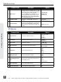
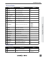
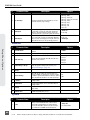
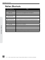
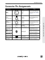
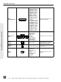
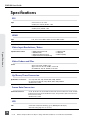
PIX 250i Rack Mount Production Video Recorder User Guide Firmware rev. 2.12 E7556 State Rd. 23 and 33, Reedsburg, WI, USA +1 (608) 524-0625 • Toll-Free: (800) 505-0625 • fax: +1 (608) 524-0655 www.sounddevices.com [email protected] PIX 250i User Guide Table of Contents Introduction 1 Manual Conventions . . . . . . . . . . . . . . . . . . . . . . . . . . . . . 1 Panel Descriptions 2 Front Panel. . . . . . . . . . . . . . . . . . . . . . . . . . . . . . . . . . . . . . 2 Rear Panel. . . . . . . . . . . . . . . . . . . . . . . . . . . . . . . . . . . . . . 3 PIX-CADDY 2 (Optional). . . . . . . . . . . . . . . . . . . . . . . . . . . 5 Menu and Navigation 6 Main View. . . . . . . . . . . . . . . . . . . . . . . . . . . . . . . . . . . . . . 6 Menu . . . . . . . . . . . . . . . . . . . . . . . . . . . . . . . . . . . . . . . . . . 7 Audio Screen. . . . . . . . . . . . . . . . . . . . . . . . . . . . . . . . . . . . 8 File List. . . . . . . . . . . . . . . . . . . . . . . . . . . . . . . . . . . . . . . . . 9 LCD. . . . . . . . . . . . . . . . . . . . . . . . . . . . . . . . . . . . . . . . . . . 11 Inputs and Outputs Video Inputs . . . . . . . . . . . . . . . . . . . . . . . . . . . . . . . . . . . 12 Video Outputs. . . . . . . . . . . . . . . . . . . . . . . . . . . . . . . . . . 12 Audio Inputs. . . . . . . . . . . . . . . . . . . . . . . . . . . . . . . . . . . 13 Audio Outputs. . . . . . . . . . . . . . . . . . . . . . . . . . . . . . . . . . 14 Ethernet 16 Video Monitoring Features 17 Exposure Assist . . . . . . . . . . . . . . . . . . . . . . . . . . . . . . . . . 17 Focus Assist . . . . . . . . . . . . . . . . . . . . . . . . . . . . . . . . . . . . 19 Zoom . . . . . . . . . . . . . . . . . . . . . . . . . . . . . . . . . . . . . . . . . 21 Flip Display. . . . . . . . . . . . . . . . . . . . . . . . . . . . . . . . . . . . . 21 Recording Sound Devices File Format. . . . . . . . . . . . . . . . . . . . . . . . File Splitting. . . . . . . . . . . . . . . . . . . . . . . . . . . . . . . . . . . . False Take. . . . . . . . . . . . . . . . . . . . . . . . . . . . . . . . . . . . . . Selecting Video File Resolution and Frame Rate . . . . . Table of Contents 12 22 22 23 23 23 Selecting a Video Codec . . . . . . . . . . . . . . . . . . . . . . . . . 24 Interruption of Signal During Recording. . . . . . . . . . . . 24 Alignment of Audio and Video . . . . . . . . . . . . . . . . . . . 24 Video Scaling and Frame Rate Conversion 26 Up and Down Conversion. . . . . . . . . . . . . . . . . . . . . . . . 27 Playback Playback Operation . . . . . . . . . . . . . . . . . . . . . . . . . . . . . 29 Shuttle Playback Mode . . . . . . . . . . . . . . . . . . . . . . . . . . 30 Cue Marker. . . . . . . . . . . . . . . . . . . . . . . . . . . . . . . . . . . . 30 29 Looping Playback. . . . . . . . . . . . . . . . . . . . . . . . . . . . . . . 31 Playback Mode. . . . . . . . . . . . . . . . . . . . . . . . . . . . . . . . . 31 Play List. . . . . . . . . . . . . . . . . . . . . . . . . . . . . . . . . . . . . . . . 32 i PIX 250i User Guide Non-Native File Playback. . . . . . . . . . . . . . . . . . . . . . . . . 33 Playing Back Files on a Computer . . . . . . . . . . . . . . . . . 33 Synchronization and Timecode Sync Reference . . . . . . . . . . . . . . . . . . . . . . . . . . . . . . . . . 35 Timecode Reader . . . . . . . . . . . . . . . . . . . . . . . . . . . . . . . 35 Internal Ambient® Lockit: Timecode Generator with Sync Out. . . . . . . . . . . . . . . . . . . . . . . . . . . . . . . . . . . . . . . . . . . 36 Timecode Modes. . . . . . . . . . . . . . . . . . . . . . . . . . . . . . . . Timecode Frame Rate. . . . . . . . . . . . . . . . . . . . . . . . . . . . Timecode Input Sources. . . . . . . . . . . . . . . . . . . . . . . . . . Synchronization/Timecode Examples. . . . . . . . . . . . . . . 34 36 37 37 37 Powering 40 Network Grouping 41 Grouped Settings . . . . . . . . . . . . . . . . . . . . . . . . . . . . . . . 41 Pushing Settings to Group. . . . . . . . . . . . . . . . . . . . . . . . 42 Group Auto-Configuration. . . . . . . . . . . . . . . . . . . . . . . 42 Grouped Transport. . . . . . . . . . . . . . . . . . . . . . . . . . . . . . 42 External Control 44 Table of Contents RS-422. . . . . . . . . . . . . . . . . . . . . . . . . . . . . . . . . . . . . . . . . 44 Web Interface - PIXNET. . . . . . . . . . . . . . . . . . . . . . . . . . 44 PIXNET Unit Page Main View and Menu Tabs . . . . . . . 48 Triggering Recording from External Timecode. . . . . . . 50 Triggering Recording from SDI Flag Bits. . . . . . . . . . . . 50 USB Keyboard. . . . . . . . . . . . . . . . . . . . . . . . . . . . . . . . . . 52 Storage and File Management Storage. . . . . . . . . . . . . . . . . . . . . . . . . . . . . . . . . . . . . . . . 53 Metadata. . . . . . . . . . . . . . . . . . . . . . . . . . . . . . . . . . . . . . 54 Setup Management and Firmware Upgrades Saving and Loading Setup Files. . . . . . . . . . . . . . . . . . . . 59 Custom Default Settings and Setup Menu Option Visibility . . . . . . . . . . . . . . . . . . . . . . . . . . . . . . . . . . . . . . . . . . . . 59 59 Factory Restore. . . . . . . . . . . . . . . . . . . . . . . . . . . . . . . . . 61 Firmware Upgrades . . . . . . . . . . . . . . . . . . . . . . . . . . . . . 61 Setup Menu Options File Storage. . . . . . . . . . . . . . . . . . . . . . . . . . . . . . . . . . . . Video . . . . . . . . . . . . . . . . . . . . . . . . . . . . . . . . . . . . . . . . . Audio. . . . . . . . . . . . . . . . . . . . . . . . . . . . . . . . . . . . . . . . . Timecode/Sync. . . . . . . . . . . . . . . . . . . . . . . . . . . . . . . . . . LCD Monitor . . . . . . . . . . . . . . . . . . . . . . . . . . . . . . . . . . . 53 File Management. . . . . . . . . . . . . . . . . . . . . . . . . . . . . . . 55 62 62 63 64 65 66 On-Screen Display. . . . . . . . . . . . . . . . . . . . . . . . . . . . . . . Remote Control. . . . . . . . . . . . . . . . . . . . . . . . . . . . . . . . . Network. . . . . . . . . . . . . . . . . . . . . . . . . . . . . . . . . . . . . . . System . . . . . . . . . . . . . . . . . . . . . . . . . . . . . . . . . . . . . . . . Quick Setup. . . . . . . . . . . . . . . . . . . . . . . . . . . . . . . . . . . . 67 67 68 68 69 Button Shortcuts 70 Connector Pin Assignments 71 Appendix A - Supported Files 73 ii v. 2.12 Features and specifications are subject to change. Visit www.sounddevices.com for the latest documentation. PIX 250i User Guide Specifications Analog Audio. . . . . . . . . . . . . . . . . . . . . . . . . . . . . . . . . . Digital Audio. . . . . . . . . . . . . . . . . . . . . . . . . . . . . . . . . . . File Storage. . . . . . . . . . . . . . . . . . . . . . . . . . . . . . . . . . . . Timecode and Sync. . . . . . . . . . . . . . . . . . . . . . . . . . . . . . Control. . . . . . . . . . . . . . . . . . . . . . . . . . . . . . . . . . . . . . . . Keyboard. . . . . . . . . . . . . . . . . . . . . . . . . . . . . . . . . . . . . . Power. . . . . . . . . . . . . . . . . . . . . . . . . . . . . . . . . . . . . . . . . Physical. . . . . . . . . . . . . . . . . . . . . . . . . . . . . . . . . . . . . . . . 75 75 75 75 76 76 76 76 Declaration of Conformity 77 Software License 78 Warranty and Technical Support 79 Table of Contents SDI. . . . . . . . . . . . . . . . . . . . . . . . . . . . . . . . . . . . . . . . . . . . 74 HDMI . . . . . . . . . . . . . . . . . . . . . . . . . . . . . . . . . . . . . . . . . 74 Video Input Resolutions / Rates. . . . . . . . . . . . . . . . . . . . 74 Video Codecs and Files. . . . . . . . . . . . . . . . . . . . . . . . . . . 74 Up/Down/Cross Conversion. . . . . . . . . . . . . . . . . . . . . . . 74 Frame Rate Conversion . . . . . . . . . . . . . . . . . . . . . . . . . . 74 LCD. . . . . . . . . . . . . . . . . . . . . . . . . . . . . . . . . . . . . . . . . . . 74 Audio Recording. . . . . . . . . . . . . . . . . . . . . . . . . . . . . . . . 75 74 iii PIX 250i User Guide Copyright Notice and Release All rights reserved. No part of this publication may be reproduced, stored in a retrieval system, or transmitted in any form or by any means, electronic, mechanical, photocopying, recording, or otherwise, without the expressed written permission of SOUND DEVICES, LLC. SOUND DEVICES is not responsible for any use of this information. Microsoft Windows is a registered trademark of Microsoft Corporation. Macintosh, OSX, and ProRes are registered trademarks of Apple, Inc. DNxHD is a registered trademark of Avid, Inc. Other product and company names mentioned herein may be the trademarks of their respective owners. PIX 250i and the sound waves logo are registered trademarks of Sound Devices, LLC. Limitation of Liability Table of Contents LIMITATION ON SOUND DEVICES’ LIABILITY. SOUND DEVICES, LLC SHALL NOT BE LIABLE TO THE PURCHASER OF THIS PRODUCT OR THIRD PARTIES FOR DAMAGES, LOSSES, COSTS, OR EXPENSES INCURRED BY PURCHASER OR THIRD PARTIES AS A RESULT OF: ACCIDENT, MISUSE, OR ABUSE OF THIS PRODUCT OR UNAUTHORIZED MODIFICATIONS, REPAIRS, OR ALTERATIONS TO THIS PRODUCT, OR FAILURE TO STRICTLY COMPLY WITH SOUND DEVICES, LLC’S OPERATING AND INSTALLATION INSTRUCTIONS. TO THE FULLEST EXTENT PERMITTED BY LAW, SOUND DEVICES SHALL HAVE NO LIABILITY TO THE END USER OR ANY OTHER PERSON FOR COSTS, EXPENSES, DIRECT DAMAGES, INCIDENTAL DAMAGES, PUNITIVE DAMAGES, SPECIAL DAMAGES, CONSEQUENTIAL DAMAGES OR OTHER DAMAGES OF ANY KIND OR NATURE WHATSOEVER ARISING OUT OF OR RELATING TO THE PRODUCTS, THESE TERMS AND CONDITIONS OR THE PARTIES’ RELATIONSHIP, INCLUDING, WITHOUT LIMITATION, DAMAGES RESULTING FROM OR RELATED TO THE DELETION OR OTHER LOSS OF AUDIO OR VIDEO RECORDINGS OR DATA, REDUCED OR DIMINISHED AUDIO OR VIDEO QUALITY OR OTHER SIMILAR AUDIO OR VIDEO DEFECTS ARISING FROM, RELATED TO OR OTHERewISE ATTRIBUTABLE TO THE PRODUCTS OR THE END USER’S USE OR OPERATION THEREOF, REGARDLESS OF WHETHER SUCH DAMAGES ARE CLAIMED UNDER CONTRACT, TORT OR ANY OTHER THEORY. “CONSEQUENTIAL DAMAGES” FOR WHICH SOUND DEVICES SHALL NOT BE LIABLE SHALL INCLUDE, WITHOUT LIMITATION, LOST PROFITS, PENALTIES, DELAY DAMAGES, LIQUIDATED DAMAGES AND OTHER DAMAGES AND LIABILITIES WHICH END USER SHALL BE OBLIGATED TO PAY OR WHICH END USER OR ANY OTHER PARTY MAY INCUR RELATED TO OR ARISING OUT OF ITS CONTRACTS WITH ITS CUSTOMERS OR OTHER THIRD PARTIES. NOTWITHSTANDING AND WITHOUT LIMITING THE FOREGOING, IN NO EVENT SHALL SOUND DEVICES BE LIABLE FOR ANY AMOUNT OF DAMAGES IN EXCESS OF AMOUNTS PAID BY THE END USER FOR THE PRODUCTS AS TO WHICH ANY LIABILITY HAS BEEN DETERMINED TO EXIST. SOUND DEVICES AND END USER EXPRESSLY AGREE THAT THE PRICE FOR THE PRODUCTS WAS DETERMINED IN CONSIDERATION OF THE LIMITATION ON LIABILITY AND DAMAGES SET FORTH HEREIN AND SUCH LIMITATION HAS BEEN SPECIFICALLY BARGAINED FOR AND CONSTITUTES AN AGREED ALLOCATION OF RISK WHICH SHALL SURVIVE THE DETERMINATION OF ANY COURT OF COMPETENT JURISDICTION THAT ANY REMEDY HEREIN FAILS OF ITS ESSENTIAL PURPOSE. iv v. 2.12 Features and specifications are subject to change. Visit www.sounddevices.com for the latest documentation. PIX 250i User Guide Introduction The PIX 250i is a rack-mountable, production video recorder with extensive audio and video processing capabilities. The foundation of the PIX 250i is hardware-based, 10-bit video up/down/cross conversion, and hardware-based encoding to Apple ProRes and Avid DNxHD codecs. These features allow for fast, reliable acquisition of video (at any standard HD or SD resolution and frame rate) and audio (up to 16 tracks from Analog, AES, HDMI, or SDI sources) to ready-for-edit, industry standard QuickTime .mov files. Files are recorded simultaneously on (up to) 2 separate, 2.5” SSD storage devices via two front panel PIX-CADDY slots. This redundancy in local, removable storage devices, coupled with standard, Ethernet-based file transfer features further reduces steps in the production workflow. Gigabit Ethernet network ports enable remote access to recorded files and the ability to transfer them quickly into a post-production environment. Full-featured precision timecode and sync reference I/O using Ambient Clockit core technology is provided to allow tight synchronization with external equipment in complex multi-machine configurations. The PIX 250i supports various external control options: RS-422, GPIO, SDI flags, Timecode triggering, and an embedded web server for network-based remote control. Network Grouping functionality enables linked, frame-synchronized recording and playback of multiple PIX 250i units connected to a standard Ethernet network. Introduction This User Guide details installation and operation of the PIX 250i. This User Guide corresponds to PIX 250i firmware version 2.12. User Guide revisions are released at the same time as firmware updates and available online: http://www.sounddevices.com/products/pix250i/downloads/ Manual Conventions Several formatting features have been included to make navigating the guide easier. • Physical buttons on the PIX 250i are represented with capital letters (REC button, MENU, etc). All physical button names are detailed in the Panel Descriptions section. • Button combinations are represented with the plus (+) symbol. For example: “Press LCD + AUDIO” means to first hold down LCD, then press AUDIO, and finally release both buttons. • Setup Menu items are indicated with this text: [Menu Category - Parameter], where the menu category is one of the items in the list displayed when MENU is pushed, and the parameter is an item in the list displayed when that category is selected (by pressing in on the Control Knob). • Blue italicized text references sections of the user guide containing contextually relevant information. When viewing this document on a computer, this text can be clicked to jump to the named section. 1 PIX 250i User Guide Panel Descriptions Front Panel Panel Descriptions 1 2 15 14 3 4 5 13 1) Control Knob The Control Knob can be both turned and pressed. Use the Control Knob to navigate between menu settings and to select menu items. Pressing during playback or stop will toggle Shuttle mode. Turning while playback is paused will jog forward or backward by single frames. 2) AUDIO Button Displays the Audio Screen. From the Audio Screen: Select audio input sources, Arm/disarm tracks, Set audio input gain and delay, View audio input levels, and Edit audio track names. 3) LCD Button Toggles the On-Screen Display. Hold for 2 seconds to toggle LCD on/off. Press to return to the Main View. 4) Handle This handle is designed to provide a gripping point for tilting down the LCD. 6 7 8 12 9 11 5) LCD Display Displays operating information when the On-Screen Display (OSD) is active(See “On-Screen Display”, page 6), user interface, source video, and playback video. 5-inch display; 800x480 resolution. 6) FILES Button Displays the File List View. Press FILES + Fast Forward (>>) during record or playback to add a Cue Marker. Press FILES + Rewind (<<) to delete a Cue Marker. 7) MENU Button Displays the Setup Menu. 8) Play Button Plays the most recently recorded file when pressed. In the File List View, plays the selected file from the File List. Toggles Play and Pause in Playback mode. Press and hold Play to activate Loop Play. (See “Playback”, page 34) 9) Stop Button Stops an active recording or playback. When Stopped, hold the Stop button to display the next filename. 2 v. 2.12 10 Features and specifications are subject to change. Visit www.sounddevices.com for the latest documentation. PIX 250i User Guide 10) Fast Forward Button When Stopped, press to cue up the next file for Playback. During Playback or Pause, press once to jump to the next Cue Marker, press and hold to increase playback speed. Continue to hold for faster speeds. 13) Headphone Volume Knob Adjusts the overall volume of the headphones. NOTE: the headphone output is capable of ear-damaging levels. Take care when adjusting among signal sources. 14) Headphone Output 1/4” TRS stereo headphone connector. Can drive headphones from 8 to 100 ohms to very high headphone levels. 11) REC Button Begins recording. Optional: Splits the recording and begins writing a new file when pressed while recording. [System - Rec Button File Split]. 12) Rewind Button When Stopped, press to cue up the previous file for Playback. During Playback and Pause, press once to jump to the previous Cue Marker or beginning of the file, press and hold to reverse playback speed. Continue to hold for faster reverse speeds. Panel Descriptions 15) USB Keyboard Input USB A female connector to connect a USB keyboard. Keyboards can be used to navigate and control the PIX 250i. Keyboards with integrated USB hubs are not compatible. Rear Panel 2 3 4 5 6 7 8 1 16 15 14 13 12 11 10 9 1) DC Power Input (XLR 4-pin) Accepts 10–27 volts DC. XLR 4-pin connector is wired pin-1 ground, pin-4 positive (+). (See “Powering”, page 40) 4) SYNC Output (BNC) Selectable Genlock or Wordclock output. Configured with Setup Menu option [Timecode/Sync - Sync Out]. 2) Timecode Output (BNC) SMPTE timecode output. 5) SYNC Input (BNC) Genlock input. Configured with [Timecode/Sync] Setup Menu options Sync Ref - Video Playback or Sync Ref - Audio Playback. 3) Timecode Input (BNC) SMPTE timecode input. 3 PIX 250i User Guide 6) Digital Audio Input/Output (DB-25) 8 channels of AES digital audio input and 8 channels of AES digital output. Outputs configured with Setup Menu option [Audio - Line Output]. (See “Connector Pin Assignments”, page 71) 7) Analog Audio Outputs (XLR) 2 channels of balanced, line-level analog audio outputs. Same signal as DB-25 Analog Audio outputs channels 1 and 2. 8) Analog Audio Inputs (XLR) 2 channels of balanced, line-level analog audio inputs. If both XLR and DB-25 signals are connected, the signal will be combined. Panel Descriptions 9) Ethernet (RJ-45) Attaches to 1G or 100M Ethernet networks. Provides Network Grouping (See “Network Grouping”, page 41), web access for remote control (See “Web Interface - PIXNET”, page 44), and network file service. (See “Storage and File Management”, page 53) 10) RS-422 Control (DB-9) Connects to RS-422 Controllers for external control of the PIX 250i. (See “RS-422”, page 44) 11) GPIO Remote (Phoenix 10-pin) Logic contact points for remote control. (See “GPIO (General Purpose Input / Output)”, page 50) 12) SDI Video Input (BNC) SDI video input. Accepts 3G-SDI, HDSDI, or SD-SDI signal with up to 16 channels of embedded audio. 13) SDI Video Output (BNC) SDI video output. Provides 3G-SDI, HDSDI, or SD-SDI signal with up to 16 channels of embedded audio. 14) HDMI Video Input (HDMI) Accepts HDMI (1.4a) signal with 8 channels of embedded audio. The PIX 250i does not record or display content encoded with HDCP. 15) HDMI Video Output (HDMI) Provides HDMI (1.3) signal with 8 channels of embedded audio. Audio configured with Setup Menu option [Audio - HDMI/AES Output]. 16) USB Connection Connect to a Windows computer to load firmware with PIX Loader software (Available on the Sound Devices website). (See “Setup Management and Firmware Upgrades”, page 68) 4 v. 2.12 Features and specifications are subject to change. Visit www.sounddevices.com for the latest documentation. PIX 250i User Guide PIX-CADDY 2 (Optional) The PIX-CADDY 2 is an accessory to connect approved 2.5” drives to the front-panel drive bays. When removed from a PIX 250i, the PIX-CADDY 2 operates as a high-speed drive interface to Mac OS and Windows computers via the onboard FireWire800, USB 3.0, or the optional PIX-DOCK Thunderbolt interface. For reliable operation, it is imperative that the 2.5” drive be firmly screwed to the PIX-CADDY 2 with the supplied screws. Some thinner drives may require the use of the PIX-SHIM accessory to ensure a solid fit. PIX-CADDY CF PIX-CADDY 2 5 3 2 6 2 8 1) FireWire 800 FireWire 800 connector. Requires a powered FireWire 800 or 400 port. Backward compatible when using Firewire 800 to 400 cable. 2) eSATAp High-speed data transfer over 5V eSATAp. Requires a 5V powered eSATAp port. 3) USB 3.0 High-speed data transfer over USB 3.0 (backward compatible with USB 2.0). 4) 2.5” Drive Slot Connector for approved 2.5-inch SATA II and SATA III drives. Sound Devices maintains a list of tested and approved SSD’s or hard drives for use with PIX video recorders. Visit www.sounddevices.com/approved for an up-to-date list of tested and approved drives. Panel Descriptions 7 4 1 5) Activity LED Illuminates when recording, playing, reading, or writing to the attached 2.5” drive. Do not remove the caddy while the Activity LED is illuminated. LED does not illuminate when connected to a computer’s eSATA port. 6) Release Latches Secures the PIX-CADDY 2 to the recorder. Press both latches to remove the caddy assembly. 7) Screw Holes For reliable operation, it is imperative that the 2.5” drive be firmly screwed to the PIX-CADDY 2 with the supplied screws. 8) CF Slot Connector for approved CompactFlash media. Sound Devices maintains a list of tested and approved CF cards. Visit www. sounddevices.com/approved for an up-todate list of tested and approved drives. 5 PIX 250i User Guide Menu and Navigation Main View The Main View displays the live or playback video and the On-Screen Display. The Main View is the default view which appears when no other views or menus are selected. On-Screen Display The On-Screen Display (OSD) provides information superimposed over the Main View. From the Main View, LCD will toggle the OSD on and off. Items included in the OSD are configured with the Setup Menu option [On-Screen Display]. When factory settings are loaded from the [Quick Setup] menu item all OSD items are shown. 1 Menu & Navigation 2 11 3 12 4 13 5 14 6 7 8 9 15 10 16 On-Screen Display Menu Item Description 1. Audio Metering Levels of audio tracks 1 and 2. Shown here in Top (wide) mode. Can be re-positioned with Setup Menu option [On-Screen Display - Audio Metering]. 2. Headphone Source Current headphone routing selection. 3. Date/Time The current time and date. 4. Group Number Displays the selected network group in [Network - Network Group] as well as the amount of units in that group in parentheses. 5. Input - Video Resolution and frame rate of the video input signal. 6. File Resolution/Rate Displays the resolution and frame rate of the file being recorded or played. The File Resolution/ Rate field is displayed in different colors to indicate conversion methods. (See “Video Scaling and Frame Rate Conversion”, page 26) 7. File Codec The presently selected video codec. This information will update for recording and playback. 8. Sync Reference The current source of synchronization. This information will update for recording and playback. 9. Cue Marker Cue marker and playback looping information is displayed here during record and playback. 6 v. 2.12 Features and specifications are subject to change. Visit www.sounddevices.com for the latest documentation. PIX 250i User Guide Item Description 10. Timecode Current timecode and frame rate of the recording or playing file. 11. Audio Source Audio sample rate, bit depth, and channel count. 12. RS-422 Status RS-422 is displayed when [Remote Control - RS-422] is on. 13. IP Address Network IP address of the PIX 250i. 14. Drive 1-2 (D1-D2) status Displays the status and remaining record time of each drive (when video input is present) or remaining space in GB (when no video input is present), Offline (when no media is present), Mounting (when media is becoming ready), No Fmt (when media is not formatted), Network (when drive mode is Ethernet File Transfer), or R/O (when drive mode is Read Only). An asterisk indicates that the drive is On in [File Storage - Drive record/Network Mode]. When recording, all drives that are being written to are displayed in red. When Stopped or in Playback, the green drive is the current default playback drive. Drive status field is orange when a drive is busy. 15. ABS Time Absolute Time: Displays the elapsed time of the file being recorded or played and the transport status (Stop, REC, Play, Fast Forward, and Rew). 16. File Name Name of the current file. Holding Stop shows the next file name. Target drives, ABS Time, File Name, Timecode, and Cue Marker OSD fields change colors to indicate the various transport states, White = Stopped, Red = Record, Green = Play/Pause, Blue = Rew/Fast Forward/Shuttle. Menu & Navigation Menu Press MENU (keyboard: F1) to enter the Setup Menu. Most settings of the PIX 250i are accessed and changed from the Setup Menu. Navigate between menu items by turning the Control Knob and pressing it to select. When in a menu, press MENU to go back to the previous screen. The Setup Menu is not accessible when in Record or Playback. If the Setup Menu is open when record or playback is engaged, the Setup Menu will close and return to the Main View. 7 PIX 250i User Guide Audio Screen From any screen, press AUDIO (keyboard: F3) to view the Audio Screen. The Audio Screen displays all audio input levels and provides configuration of Track Arming, Track Naming, Input Source selection, Input Gain, and Input Delay. The Audio Screen by default displays 16 tracks at a time. This can be changed to 8 or 16 track displays in [Audio - Audio Screen Meters]. To make adjustments in the Audio Screen: 1. Rotate the Control Knob to move the blue highlighter to the desired track. 2. Press the Control Knob to focus the highlighter on parameters for the track. The highlighter will become orange. 3. Rotate the Control Knob to move the orange highlighter to the desired parameter. 4. Press the Control Knob to edit the highlighted parameter. 5. Rotate the Control Knob to adjust the value or setting. If editing Track Names, use the the onscreen keyboard or attached USB keyboard. 6. Press the Control Knob to save the new setting. The highlighter will become blue and once again highlight the entire track. Menu & Navigation Sync Source/Sample Rate Absolute Time Transport Status Headphone Source Highlighted Track Drive Statuses Timecode Value Timecode Frame Rate File Name Expanded Meters Press AUDIO while viewing an Audio Screen to toggle Expanded Meters. Input Source, Gain, and Delay parameters are removed to accommodate for higher resolution meters. 8 v. 2.12 Features and specifications are subject to change. Visit www.sounddevices.com for the latest documentation. PIX 250i User Guide Other audio related settings are accessible from the Setup Menu option Audio. File List Press FILES (keyboard: F2) to display the File List; A list of all of the recorded takes. Takes are arranged chronologically and grouped by Reel. Turn the Control Knob to highlight an item. Press Play to start playback of the highlighted take. Press the Control Knob (Press and hold for multi-file clips) to perform functions based on which item is highlighted. 1 2 Menu & Navigation 3 4 5 6 1) Next Take Information for the next take. 2) Current Take Information for the current take. Item is red while recording. 3) Reel Group A group of clips organized by reel number. Takes below are part of the indicated reel. Number in brackets indicates number of clips in the reel. Press Control Knob to expand or collapse list of takes in this reels. 4) Multi-File Take Take consisting of multiple files. Number of files in the take represented by number in brackets. Press Control Knob to expand or collapse list of files in this take. Press and hold Control Knob to access take details for all files in the take. 7 8 5) Take Represents a single take. Press Control Knob to view Take Details Screen. Press Play to play take immediately. 6) Name The name or number of the take, file, or reel. Number in brackets indicates amount of clips in the reel or amount of files in the take. 7) Date and Time Date and time the take or reel was created. 8) Size Total size of the take, file, or reel. 9 PIX 250i User Guide The selected drive is displayed on the top of the screen. To view the contents of other drives, scroll to the top of the list. A pop up box appears with a list of all available drives. Select the desired drive and press the Control Knob. While in the File List press FILES to collapse all Reel folders and multi-file takes to ease file navigation. Take Details Screen From the File List, highlight a file and press the Control Knob to view the Take Details Screen. To view Multi-file Take details, highlight the menu item with the file extension then press and hold the Control Knob. Take Details include: Menu & Navigation • Start timecode • Timecode frames-per-second • Timecode user bits • Video resolution and rate • File creation date and time • Video codec • Media • File size • Duration • Audio Format File functions are also available in the Take Details Screen: • Delete: Deletes the take or file (Confirmation dialog). (See “Deleting a File”, page 57) • Add to Play List: Adds the take to the Play List. (See “Play List”, page 32) • Remove from Play List: Removes the take from the Play List. (See “Play List”, page 32) • Empty Play List: Empties the entire Play List. (See “Play List”, page 32) 10 v. 2.12 Features and specifications are subject to change. Visit www.sounddevices.com for the latest documentation. PIX 250i User Guide LCD From the Main View (See “Main View”, page 6), press LCD to toggle the On-Screen Display (OSD) on or off, press and hold LCD for two seconds to turn off the LCD, press again to turn on. From all other views, press LCD to return to the Main View. Menu & Navigation The LCD Control Panel provides adjustments to the LCD backlight, image brightness, image contrast, image chroma, and button backlight. To access the LCD Control Panel, press LCD + Control Knob. The parameter with the orange slider bar is the selected parameter. To toggle through the parameters press the Control Knob. To adjust the setting, turn the Control Knob. Press LCD again to exit back to the Main View. 11 PIX 250i User Guide Inputs and Outputs Video Inputs The PIX 250i accepts video input signals over HDMI, HD-SDI, and single link 3G-SDI Level A and B. The PIX 250i does not accept analog video signals. See the Specifications section for a complete list of supported frame rates. HDMI The PIX 250i accepts HDMI version 1.4a video and audio. Supported video resolutions and rates are listed in the Specifications section. The PIX 250i HDMI input accepts up to 10-bit, 4:4:4 video, up to 8 channels of embedded audio. The PIX 250i also accepts Sony’s proprietary timecode over HDMI. The digital audio embedded in the HDMI stream (32 kHz – 192 kHz) is always re-sampled to 48 kHz. 720p30/29.97, 720p25, and 720p24/23.976 are not supported on the HDMI input or the HDMI output. Inputs & Outputs HDCP copy protection prevents direct digital-to-digital copying of copyrighted material. Protected DVDs, Blu-Rays, and streaming content with HDCP encryption is not valid content and will be ignored by the PIX 250i. SDI The SDI input on the PIX 250i accepts video with embedded audio (up to 16 channels) and embedded SMPTE timecode. This connection accepts digital video up to 12-bit, with up to 4:4:4 color sampling. Unlike the HDMI interface, which auto-negotiates rates between devices, what comes out of a camera’s SDI output is received by the PIX 250i with no auto-negotiation or sample rate conversion. The PIX 250i supports 3G-SDI single link, but not dual-link HD-SDI. Timecode over SDI is not available when recording in standard definition Video Outputs Both HDMI and SDI outputs are active simultaneously. This allows for conversion from SDI to HDMI and HDMI to SDI. The output video signal source is the signal present at the currently selected video input (Setup Menu option [Video - Video Input]), except during video playback. The resolution and frame rate of the output stream is determined by the Setup Menu option [Video - File Resolution/Rate] setting, except during video playback. The SDI Output is capable of sending HD (4:2:2 10-bit) or 3G (4:4:4 12-bit), this is set in [Video - SDI Output Type].Video playback signal is sent to the HDMI and SDI Outputs. Standard Definition video is always output using HD Mode because 3G does not support Standard Definition. 12 v. 2.12 Features and specifications are subject to change. Visit www.sounddevices.com for the latest documentation. PIX 250i User Guide The output video stream contains up to 16 tracks of embedded audio for SDI and 8 tracks for HDMI. Timecode and record start and stop flags are included on the SDI output. Timecode overlay can be added to the HDMI and/or SDI output signal in [Video - Video Output OSD]. The timecode overlay is displayed in various colors to indicate the current transport state of the PIX 250i: White = Stopped, Red = Record, Green = Playback. Audio Inputs The PIX 250i can record up to 16 tracks from a variety of audio input sources: Input Type Count Connector(s) Gain Off, -25 to 20 dB Details Analog 2 1-2: XLR (LINE IN 1/2) Balanced, Line-level, XLR. AES Digital 8 -25 1-8: DB-25 (CH 1-8 AES IN/OUT) Off, to 50 dB Selectable between AES or HDMI with Setup Menu option [Audio - HDMI/AES Select] HDMI Digital 8 1-8: HDMI Input Off, -25 to 20 dB Selectable between AES or HDMI with Setup Menu option [Audio - HDMI/AES Select] SDI Digital 16 1-16: SDI Input Off, -25 to 20 dB Analog Audio Inputs Inputs & Outputs The PIX 250i has two, high-performance, line-level analog audio inputs on XLR3-M connectors. Digital Audio Inputs The PIX 250i accepts digital audio from HDMI, SDI, and AES/EBU inputs. All audio is sampled at 48kHz. AES3 The PIX 250i accepts AES3 (AES/EBU) digital signals with sampling rates from 32 kHz up to 192 kHz and bit depths up to 24-bits. AES3 inputs are sample rate converted to 48 kHz. HDMI / SDI Embedded Audio The PIX 250i accepts 8 channels of embedded digital audio on the HDMI Video Input or 16 channels of digital audio on the SDI input. Sample Rate Converters All digital inputs have Sample Rate Converters. These help ensure synchronization of digital audio from multiple sources. Choosing Audio Sources Audio Input Source is selected in the Audio Screen in the Source column. To setup an input: 1. Press AUDIO to access the Audio Screen. If the Source column is not visible, press AUDIO again to reveal it. 2. Rotate the Control Knob to select the desired track. 3. Press the Control Knob to focus the highlighter on the selected track’s parameters. The highlighter will become orange and focus on a single column in the track. 4. Rotate the Control Knob to highlight the Source column. 13 PIX 250i User Guide 5. Press the Control Knob to open the Audio Source options window. Select the general type of input to be used from Off, Line In, HDMI/AES In, or SDI In and press the Control Knob again to open up all options for that input type. 6. Press the Control Knob to make a selection and exit the Audio Input Source options window. For quick general audio source configurations use [Audio - Audio Input Quick Setup]. (See “Setup Menu Options”, page 62) Input Gain Control Audio Input Gain is set in the Audio Screen in the Gain column. To adjust the gain of an audio track: 1. Press AUDIO to access the Audio Screen. If the Gain column is not visible, press AUDIO again to reveal it. 2. Rotate the Control Knob to select the desired track. 3. Press the Control Knob to focus the highlighter on the selected track’s parameters. The highlighter will become orange and focus on a single column in the track. 4. Rotate the Control Knob to highlight the Gain column. 5. Press the Control Knob to edit the gain value. Turn the Control Knob to adjust the gain in 1 dB increments. Gain is adjusted in real time. The available gain range depends on the audio input source. (See “Audio Inputs”, page 13) Inputs & Outputs 6. Once the desired gain value is set, press the Control Knob to exit the gain window. Input Gain can be linked in [Audio - Input Gain Linking]. When linked, adjust any channel’s gain value to adjust the gain of all channels. Gain offsets from channel to channel are maintained. If this is not desired, unlink the gain and set all gain values to the same value, then re-link input gain. Input Delay Control Audio Input Delay is set in the Audio Screen in the Delay column. Delay is adjustable from 0 to 400 mS. To adjust the delay of an audio track: 1. Press AUDIO to access the Audio Screen. If the Delay column is not visible, press AUDIO again to reveal it. 2. Rotate the Control Knob to select the desired track. 3. Press the Control Knob to focus the highlighter on the selected track’s parameters. The highlighter will become orange and focus on a single column in the track. 4. Rotate the Control Knob to highlight the Delay column. 5. Press the Control Knob to edit the delay value. Turn the Control Knob to adjust the delay in 1 mS increments. 6. Once the desired delay value is set, press the Control Knob to exit the delay window. Input Delay can be linked in [Audio - Input Delay Linking]. When linked, adjust any channel’s delay value to adjust the delay of all channels. Delay offsets from channel to channel are maintained. If this is not desired, unlink the delay and set all delay values to the same value then re-link input delay. Audio Outputs Analog Audio Outputs The two analog outputs of the PIX 250i are active-balanced, line-level outputs (+18dBu max). At factory default, the source of the Analog Line Outputs 1-2 is tracks 1 and 2, respectively. 14 v. 2.12 Features and specifications are subject to change. Visit www.sounddevices.com for the latest documentation. PIX 250i User Guide Any of the available 16 Tracks can be sent to the Line Outputs. Line Output routing is set in [Audio - Line Output]. Digital Audio Outputs (HDMI/AES) AES and HDMI Outputs are active at all times but these two outputs share the same source. At factory default, the source of the HDMI/AES Outputs 1-8 is tracks 1 to 8, respectively. Any of the available 8 Tracks can be sent to the HDMI/AES Outputs. HDMI/AES Output routing is set in [Audio - HDMI/AES Output]. SDI Audio Outputs The SDI video output embeds up to 16 channels of digital audio. At factory default, the source of the SDI Audio Outputs 1-16 is tracks 1 to 16, respectively. Any of the availabe 16 Tracks can be sent to the SDI Output. SDI Output routing is set in: [Audio - SDI Output]. Headphone Output The PIX 250i is capable of driving headphones to extremely high sound pressure levels. Hearing experts advise against exposure to high sound pressure levels for extended periods. Inputs & Outputs The PIX 250i’s headphone output is a flexible tool for monitoring audio. The headphone level is adjusted using the Headphone Volume Knob. To quickly select a headphone source, press and hold AUDIO, then turn the Control Knob. The Headphone Source can also be selected in the Setup Menu option [Audio - HP Source]. To solo a track, enter the Audio Screen, highlight the track, then press AUDIO + LCD. The solo headphone source will be indicated on the top-left of the Audio Screen (HP: Solo8 for example). To stop solo of a track, highlight the soloed track, then press AUDIO + LCD. Warning Bells are sent to the headphone monitor to alert the user of various states such as transport changes, and errors such as No Media Connected or No Input Signal Detected. The loudness of these warning bells is adjustable from Off, -60 to -12 dBFS in [System - HP Warning Bell Level]. At factory default, the warning bells are set to -40 dBFS. 15 PIX 250i User Guide Ethernet The PRI and SEC Ethernet ports on the rear panel of the PIX 250i are used for a variety of PIX 250i functions/features: • Network Grouping (See “Network Grouping”, page 41) • File Transfer (Samba) (See “Transferring Files”, page 57) • Web Browser Control (See “Web Interface - PIXNET”, page 44) Up to four PIX 250i units can be daisy-chained using their built-in Ethernet switches. If using five or more PIX 250i units, Sound Devices recommends using an external Ethernet Switch in a star configuration. The PIX 250i can either be allocated an IP address from a DHCP server (recommended) or over Linklocal networking. Link-local networking is a protocol which automatically allocates a 169.254.x.x IP address in the absence of any DHCP server. If a DHCP server is available, the PIX 250i will automatically use it if [Network - Auto IP Settings] is set to On. Inputs & Outputs Alternatively, the IP address can be configured manually. When Setup Menu option [Network - Auto IP Settings] is set to Off, Setup Menu options [Network - IP Address], [Network - Subnet Mask], and [Network - Gateway] are enabled. When these settings are improperly set, the PIX 250i may be unreachable in the network or may cause conflicts resulting in other devices in the network being unreachable. Consult with an IT technician to determine the appropriate settings when connecting to a large network. The PIX 250i uses on-board Auto-MDIX (crossover detection) to allow for direct connection to a computer or to a network. 16 v. 2.12 Features and specifications are subject to change. Visit www.sounddevices.com for the latest documentation. PIX 250i User Guide Video Monitoring Features The PIX 250i includes various monitoring features to assist with exposure and focus. These functions only affect signal on the LCD display and will never affect the recorded video or the video output signal. Exposure Assist LCD + FILES Video Monitoring Features Exposure assist features mark areas of the video image based on the exposure level. With over- or under-exposed areas of the image clearly marked, adjustments can be made on the camera to ensure that the signal reaching the recorder has a proper exposure. Exposure Assist is enabled by pressing LCD + FILES. When Exposure Assist is enabled, “EXP” is displayed on the OSD in yellow text. When exposure assist is enabled, False Color or Zebra stripes will be overlaid on the LCD monitor signal. The Setup Menu option [LCD Monitor - Exposure Assist] determines which mode will activate when exposure assist is toggled on. The following image is a luminance ramp signal displayed on a PIX 250i with no exposure assist enabled. Screen shots in the following sections show the effect of the various Exposure Assist features on this test signal. False Color False Color exposure assist mode replaces pixels with a specific color relative to the luminance level. The two types of False Color (selectable from Setup Menu option [LCD Monitor - Exposure Assist]) are 12-step and 4-step. 17 PIX 250i User Guide 12-step False Color mode divides the monitor signal into 12 luminance ranges and assigns a color to each. 12-step 100-108 Red 95-99 Orange 85-94 Yellow 79-84 Light Yellow 59-78 Light Grey 53-58 Pink 49-52 Medium Grey 43-48 Green 23-42 Dark Grey 13-22 Light Blue 3-12 Blue 0-2 White Video Monitoring Features 4-step False Color mode divides the monitor signal into 4 ranges and assigns a color to all but one range (this range is displayed without chroma). The table below illustrates the colors as they relate to luminance levels (IRE). 4-step 101+ Red 99-100 Orange 3-98 N/A 0-2 Blue Zebras Zebra stripe exposure assist mode overlays diagonal stripes over areas that are in a defined luminance range (Zebra 1) or above a defined luminance threshold (Zebra 2). The range for Zebra 1 is 5% above and below the IRE value of Setup Menu option [LCD Monitor - Zebra 1 Level]. The range for Zebra 2 is everything above the IRE value of Setup Menu option [LCD Monitor - Zebra 2 Threshold]. The options for Zebra display (selectable from Setup Menu option [LCD Monitor - Exposure Assist]) are Zebra 1, Zebra 2, or both Zebra 1 and Zebra 2 simultaneously. 18 v. 2.12 Features and specifications are subject to change. Visit www.sounddevices.com for the latest documentation. PIX 250i User Guide Zebra 1 85 IRE Video Monitoring Features Zebra 2 70 IRE (+/- 5%) Focus Assist LCD + MENU Focus Assist features mark sharp edges in the video image to assist in focusing on the desired subject. Focus assist is enabled pressing LCD + MENU. The word “FOCUS” is displayed in yellow text on the OSD when Focus Assist is enabled. There are two available Focus Assist modes: Peaking and Edge Enhance. Peaking Peaking finds sharp edges in a video (based on luminance) and replaces pixels in those areas to highlight the edges. The Setup Menu option [LCD Monitor - Peaking Sensitivity] sets sensitivity level of the Peaking filter. A setting of High will be more sensitive and highlight more edges. The Setup Menu option [LCD Monitor - Peaking Background Contrast] is used to adjust the area of the video image that is not highlighted while Peaking is enabled. The color of the Peaking marks can be set with the Setup Menu option [LCD Monitor - Peaking Color]. The following image comparison demonstrates the effect of Peaking on an image with a shallow depth-of-field and a short focal length (top) and a longer focal length (bottom). 19 PIX 250i User Guide Video Monitoring Features Edge Enhance The Edge Enhance filter uses an algorithm which enhances the variation of the luminance of all edges present in the video image. The following image comparison demonstrates the effect of Edge Enhance on an image with a shallow depth-of-field and a short focal length (top) and a longer focal length (bottom). 20 v. 2.12 Features and specifications are subject to change. Visit www.sounddevices.com for the latest documentation. PIX 250i User Guide Zoom LCD + AUDIO The Zoom function enlarges the video image to a 1:1 pixel ratio. To toggle Zoom on and off, press LCD + AUDIO. When Zoom is enabled, “ZOOM” is displayed on the OSD in yellow text and all other OSD elements are hidden. When zoomed, turning the Control Knob moves vertically and Rewind and Fast Forward buttons move left and right, respectively. Flip Display Video Monitoring Features Some mounting situations require the PIX 250i (or camera) to be upside-down. The LCD output can be vertically inverted to facilitate upside-down operation with the Setup Menu option [LCD Monitor - Verical Flip Display]. The Setup Menu option [LCD Monitor - Horizontal Flip Display] option reverses the LCD output signal hoizontally (mirror image). Vertical and Horizontal flipping affect the video image on the LCD screen only. Recorded content and HDMI/SDI outputs are not affected. 21 PIX 250i User Guide Recording The PIX 250i records video and audio together to a QuickTime .mov file. The PIX 250i can record to up to two drives simultaneously or in sequence (Setup Menu option [File Storage - Video Record Mode]). Each drive can be configured independently to be available for recording, available for playback (read-only), shared on the network via Samba, or switched to network sharing after becoming full (Setup Menu option [File Storage - Drive Record/Network Mode]). Any number of PIX 250i units can be assigned to one of four available network groups for grouped record and playback of video on multiple units simultaneously (See “Network Grouping”, page 41). Pressing the REC button will start recording provided there is valid video signal present. Recording will continue until the Stop () button is pressed or until all available media is full. Record and Stop can also be triggered by other devices via a web browser, RS-422, GPIO, SDI Triggers, and Timecode. External control of such functions is set in Remote Control. (See “External Control”, page 50) (See “Synchronization and Timecode”, page 39) While recording, the REC button will illuminate red and the OSD items Timecode, File Name, ABS Time, and drives actively recording turn red. The PIX 250i is a record-priority device and will enter record any time the REC button is pressed. If the PIX 250i is not ready to record when a record command is given, the PIX 250i will enter a Record Pending state. In this state the REC button will flash red. This is usually caused by file storage mounting or response time, loss of video input, or Play/ Pause/Shuttle. Recording The Setup Menu is not accessible during recording and playback. The File List is not accessible during Playback. Sound Devices File Format During recording the PIX 250i writes to a temporary file format. Files are written with the extension .SDV. When recording is stopped, the file is “finalized” to a standard Quicktime (.mov extension). The Sound Devices file format allows for reliable recovery of content in situations where power was lost or a drive was removed during recording. Upon powering up, the PIX 250i will search for any 22 v. 2.12 Features and specifications are subject to change. Visit www.sounddevices.com for the latest documentation. PIX 250i User Guide .SDV files on all drives and finalize them to the standard Quicktime file format with a .MOV extension. .SDV files can also be recovered to .MOV files on a Windows computer using the FileSafe utility. (See “FileSafe Utility and the Sound Devices File Format”, page 58) File Splitting Recorded video files are split automatically at the interval selected in Setup Menu option [File Storage - QuickTime File Split every]. When the Setup Menu option [System - REC button File Split] is set to On, pushing the REC button during recording will split the file manually. When a split occurs, a new file will be created and grouped with the other files from the clip in the File View. (See “Storage and File Management”, page 59) Audio tracks on video files will not split seamlessly. Some small, brief clicks may occur on some audio tracks in split video files. The video content of video files will always split seamlessly. False Take Recording To discard the last take and delete the file (False take), press Stop () button + Rewind (<<) button. A dialog box will appear warning that the last take will be deleted and indicate the file name. Use the Control Knob to highlight OK and press the Control Knob to confirm. Selecting Video File Resolution and Frame Rate The PIX 250i can record video in numerous resolutions and frame rates. The Setup Menu option [Video - File Resolution/Rate] sets the resolution and frame rate of recorded QuickTime files. This Setup Menu option also determines the resolution and frame rate of the live HDMI and SDI output signals, except during playback. The PIX 250i can record QuickTime files in the following resolutions and frame rates: • 1080 p 30 • 1080 p 29.97 • 1080 p 25 • 1080 p 24 • 1080 p 23.976 • 1080 i 60 • 1080 i 59.94 • 1080 i 50 • 1080 PsF 30 • 1080 PsF29.97 • 1080 PsF 25 • 1080 PsF 24 • 1080 PsF 23.976 • 720 p 60 • 720 p 59.94 • 720 p 50 • 720 p 30 ** • 720 p 29.97 ** • 720 p 25 ** • 720 p 24 ** • 720 p 23.976 ** • 576 i 50 * • 480 i 59.94 * When Setup Menu option [Video - File Resolution/Rate] is set to Same as Video Input, recorded QuickTime files and video output signals will be of the same resolution and frame rate as the input video signal. * Standard definition recording is only available for ProRes 422 HQ, ProRes 422, and ProRes 422 Proxy. ** Not supported over HDMI 23 PIX 250i User Guide Progressive Segmented Frames (PsF) Some cameras output video signal in progressive segmented frames (PsF). PsF is a method for transmitting progressive video in an interlaced stream. A device generates PsF signal by splitting each frame into two segments. PsF segments are the same as interlaced fields in that one segment represents the even lines of a frame and the other segment represents the odd lines of a frame. PsF segments differ from interlaced fields in that there is no motion between each segment in a pair. The PIX 250i will automatically sense PsF signal from most cameras that output PsF over SDI. This is accomplished through the use of a flag inserted into the SDI signal by the camera. If a camera does not insert this flag into the SDI stream or if it outputs PsF signal over HDMI, then the Setup Menu option [Video - Input PsF Detect] can be set to Interpret 1080i as PsF. This will force the PIX 250i to treat all 1080i signal as if it were PsF and deinterlace it accordingly. Selecting a Video Codec Setup Menu option: [Video - Codec]. The PIX 250i has two families of intra-frame, DCT-based codecs available: Apple ProRes and Avid DNxHD, with five levels of compression for ProRes and four levels of data compression available for DNxHD. Both codecs are intermediate codecs that assist the editing process by eliminating the need to transcode video before importing into Final Cut (ProRes) or Avid (ProRes or DNxHD). Recording ProRes is a variable data rate codec and DNxHD is a fixed data rate codec. PIX 250i supports all compression levels and bit rates of ProRes and DNxHD and automatically records the correct bit rate dependent upon the video input resolutions and frame rate. The data rates indicated in the Setup Menu item [Video - Codec] indicate the maximum data rate at 1080p30. DNxHD 36 Mb/s only supports 1080p signal. Standard definition recording is only available for ProRes 422 HQ, ProRes 422, and ProRes 422 Proxy. Interruption of Signal During Recording In the event that video signal is lost (an unplugged HDMI or SDI cable, for example) during recording, the PIX 250i will pause the recording and wait for video signal to be re-initialized. If video signal is re-initialized, recording will begin again to a new file of the same name with an “A” appended to the end. Further interruptions of signal during that take will cause an alphabetic filename progression (“B”, “C”, etc). Alignment of Audio and Video An advantage to recording audio on the PIX 250i along with the video is the elimination of audio/ video sync problems in post. The PIX 250i has many options regarding audio sources along with the two options for video inputs, HDMI and SDI. Given this flexibility, care must still be taken to ensure good audio/video sync. If recording camera audio embedded on HDMI or SDI, then the audio/video alignment will be excellent provided the alignment is proper on the camera. If recording audio using the dedicated audio inputs (Analog or AES), then a delay may need to be dialed in. The reason for this is that some cameras have a delay of one or more frames from lens to SDI/HDMI output. The PIX 250i on the other hand has no appreciable delay between audio and video. This means that if the camera does have this delay, the audio will lead the video as recorded by the PIX 250i. Note that on some cameras, the lens-to-SDI/HDMI delay changes with resolution/ 24 v. 2.12 Features and specifications are subject to change. Visit www.sounddevices.com for the latest documentation. PIX 250i User Guide frame rate. The best practice is to test the audio/video sync using a clapper slate on a test file for each camera resolution/frame rate to be used on a project before starting. See Audio Input Delay Control for details Audio Track Arming Up to 16 Tracks of audio can be recorded. Tracks must be armed in the Audio Screen in order for them to be recorded. Armed audio tracks will have a red background in the Arm column. Unarmed audio tracks will have a black background in the Arm column. To arm or disarm Tracks for recording: 1. Press AUDIO to access the Audio Screen. 2. Rotate the Control Knob to select the desired track. 3. Press the Control Knob to focus the highlighter on the selected track’s parameters. The highlighter will become orange and focus on a single column in the track. 4. Rotate the Control Knob to highlight the Arm column (The Arm column is the left-most column and displays the track number). 5. Press the Control Knob to access the Arm Menu. Turn the Control Knob to select On, Off, All On, or All Off. (All On and All Off will change the arming status of all tracks, regardless of which track is selected). Recording Changing a track’s Input Source to Off will disarm the track. 25 PIX 250i User Guide Video Scaling and Frame Rate Conversion The PIX 250i features powerful, hardware-based video scaling, frame rate conversion, and de-interlacing. This allows for converting the resolution and frame rate of input video signal to the recorded file and to the HDMI and SDI outputs in real-time. Video Scaling & Frame Rate Conversion Video scaling and/or de-interlacing is active whenever the Setup Menu option [Video - File Resolution/Rate] is set to something other than Same as Video Input. Any supported input signal can be converted to any available resolution. When set to record progressive frames, the PIX 250i will convert incoming interlaced video to progressive frame video via its built-in, powerful, hardware-based de-interlacer. The PIX 250i will also convert progressive segmented frame (PsF) video to progressive video automatically if Setup Menu option [Video - File Resolution/Rate] is set to a progressive frame format (for example 1080p30). If Setup Menu option [Video - File Resolution/Rate] is set to interlaced format (for example 1080PsF30), the PIX 250i will record PsF signal unaltered, but the file will be stamped as interlaced. Frame rate conversion occurs whenever the frame rate of [Video - File Resolution/Rate] differs from the frame rate of the input video signal. Frame rate conversion is achieved by appropriately duplicating or dropping frames. The PIX 250i will auto-sense between integer and non-integer frame rates (for instance 30 frames vs. 29.97 frames). The PIX 250i will not frame rate convert between integer and non-integer frame rate values. For example, if the incoming video signal is 1080i59.94, it can be converted to 1080p29.97 or 720p59.94 but not 1080p30 or 720p60. The Setup Menu option [Video - File Resolution/Rate] contains entries with a combination of integer and non-integer frame rates (such as 1080p30/29.97). When any of these options are selected, the PIX 250i will record in the indicated integer frame rate if the input video is an integer frame rate or record in the indicated noninteger frame rate if the input video is a non-integer frame rate. Not all frame rate conversions are visually desirable. When the OSD Item File Resolution/Rate is red, the conversion of the frame rate of the input video will contain a finite amount of motion judder. For example, if the incoming video is 720p60 and [Video - File Resolution/Rate] is set to 720p50, the cadence of dropped frames may be noticeable depending on the content. Conversions that are simply 1:2 or 2:1 (such as 1080i59.94 to 1080p29.97) introduce no motion judder. For these conversions, the OSD Item File Resolution/Rate remains white. When the input video signal is 720p24 or 720p23.976, up-, down-, and cross-conversion is not available. 3:2 Pulldown Removal Many cameras which shoot with a shutter speed of 24/23.976 frames per second will output signal on the HDMI or SDI output at 60i/59.94i. To achieve this, the camera performs a “3:2 pulldown” process. The 3:2 pulldown process splits each frame into 2 fields and duplicates a field periodically. The PIX 250i is capable of removing 3:2 pulldown from a 60i/59.94i signal and converting it back to 24/23.976 progressive frames per second in real-time. The PIX 3:2 removal process actively views video fields looking for duplicates. When these duplicates are sensed, then this cadence is locked in and the appropriate extra fields are removed. The process depends on motion in the incoming video. The OSD item File Resolution/Rate changes from orange to white when this cadence is detected: 26 v. 2.12 Features and specifications are subject to change. Visit www.sounddevices.com for the latest documentation. PIX 250i User Guide Orange: No 3:2 pulldown sensed in 60i/59.94i input signal. Input video is being converted to 24p/23.976p using a conversion process which drops frames and may introduce judder. White: 3:2 pulldown sensed in 60i/59.94i input video signal. Input video signal is being converted to 24p/23.976p using 3:2 pulldown removal which recreates 24p/23.976p as it is captured from the camera’s shutter. Video Scaling & Frame Rate Conversion It is important that 3:2 pulldown be sensed before beginning a recording. If recording begins before 3:2 pulldown is sensed, 3:2 pulldown will not be applied properly. Up and Down Conversion Standard-definition video resolution employs a 4:3 aspect ratio, and high-definition video resolution employs a 16:9 aspect ratio. Up-conversion is the process of fitting standard-definition video (with a 4:3 aspect ratio) into a high-definition, 16:9 frame. Down-conversion is the opposite process. The PIX 250i has various options for up and down conversion: Down-Conversion Letterbox: Maintains the same height and width ratio. Results in blank bar at top and bottom of image. Crop: Left and right side of image is cropped to fit into 4:3. Results in missing image at sides of picture. Anamorphic: Image is horizontally squashed to fit into 4:3. Results in a narrow looking image. 16 4 9 Letterbox 3 Crop Anamorphic 27 PIX 250i User Guide Up-Conversion Anamorphic: Image is horizontally stretched to fit into 16:9. Results in a wide looking image. Pillarbox: Increases size and maintains same ratio. Results in blank bar at right and left of image and picture cropped at top and bottom. Zoom 14x9: Maintains same size but fills in remaining screen space with blank bar on the right and left of image. Zoom Wide: Increase size and maintains ratio to full screen 16:9. Results in top and bottom being cropped. 4 16 Video Scaling & Frame Rate Conversion 3 Anamorphic Pillarbox Zoom 14x9 Zoom Wide 28 v. 2.12 Features and specifications are subject to change. Visit www.sounddevices.com for the latest documentation. 9 PIX 250i User Guide Playback The PIX 250i has a very powerful playback engine that allows for playback of QuickTime .mov files whether generated by the PIX 250i or elsewhere (See “Appendix A - Supported Files”, page 73). Playback video is shown on the onboard LCD display and is sent to the video outputs. The PIX 250i’s video playback clock is determined by the setting in [Timecode/Sync - Sync Ref - Video Playback]. Any number of PIX 250i units can be assigned