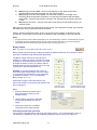
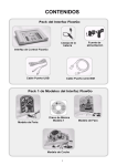
1
DO172 (3) The Go Software User Guide The Go Software User Guide © Data Harvest Group Ltd. 1 DO172 (3) The Go Software User Guide Contents Overview ....................................................................................................................................... 4 The ACEs supplied.................................................................................................................... 4 ACE Town scenario ............................................................................................................... 4 ACE Model Pack 1 and 2....................................................................................................... 5 ACE Interfaces ....................................................................................................................... 5 Example control programs ..................................................................................................... 5 Go operating modes .................................................................................................................. 5 System Requirements ................................................................................................................... 6 Installing the Go software.............................................................................................................. 6 Connecting an Interface ................................................................................................................ 6 Starting Go for the first time .......................................................................................................... 7 Step 1: Selecting a User level ................................................................................................... 7 Step 2: Interface selection ......................................................................................................... 7 Connecting to an ACE................................................................................................................... 8 The ACE window ....................................................................................................................... 8 Sync and Simulation modes ...................................................................................................... 9 The Go screen layout .................................................................................................................. 10 Toolbars................................................................................................................................... 10 The Standard and Control toolbar........................................................................................ 10 The flowchart or procedure selector toolbar ........................................................................ 11 The Symbol toolbar.............................................................................................................. 11 The Map and Text View ....................................................................................................... 11 I/O and Variable panels ....................................................................................................... 12 Program terminology ................................................................................................................... 12 Placing symbols and entering commands .................................................................................. 13 Connecting the symbols.............................................................................................................. 13 Deleting flow lines.................................................................................................................... 14 Running a control program.......................................................................................................... 14 The Symbols ............................................................................................................................... 14 Selection .................................................................................................................................. 14 The Start symbol...................................................................................................................... 15 Start (Flowchart)................................................................................................................... 15 Procedure............................................................................................................................. 15 The Output symbol .................................................................................................................. 16 Switch Output....................................................................................................................... 16 Switch Motor ........................................................................................................................ 16 Sound................................................................................................................................... 16 Binary Output ....................................................................................................................... 17 The Process symbol ................................................................................................................ 18 Wait ...................................................................................................................................... 18 Procedure............................................................................................................................. 18 Make .................................................................................................................................... 19 The Decision symbol ............................................................................................................... 21 Is Input ................................................................................................................................. 21 Is Sensor .............................................................................................................................. 21 Is Variable ............................................................................................................................ 22 Is Binary Input ...................................................................................................................... 22 The Stop symbol...................................................................................................................... 23 Stop...................................................................................................................................... 23 Stop All................................................................................................................................. 23 Flow Line ................................................................................................................................. 23 Text Tool.................................................................................................................................. 24 © Data Harvest Group Ltd. 2 DO172 (3) The Go Software User Guide Delete ...................................................................................................................................... 24 New.......................................................................................................................................... 24 Creating multiple flowcharts ........................................................................................................ 24 Uses for running separate flowcharts .................................................................................. 25 Making flowcharts ‘talk’ to each other .................................................................................. 25 Creating Procedures ................................................................................................................... 25 Using Learn ................................................................................................................................. 26 To check and debug a control program ...................................................................................... 26 Start Settings ........................................................................................................................... 26 Run only the current procedure or flowchart ........................................................................... 26 Pause and Single Step ............................................................................................................ 26 Single Step .............................................................................................................................. 27 Breakpoints.............................................................................................................................. 27 Follow Flowchart...................................................................................................................... 27 Downloading your program ......................................................................................................... 28 Stored program limits .............................................................................................................. 28 Download Program Limits ....................................................................................................... 28 Set Interface Sensors.................................................................................................................. 29 Select, Copy and Paste............................................................................................................... 29 Saving and Opening files ............................................................................................................ 29 Printing ........................................................................................................................................ 30 Options ........................................................................................................................................ 31 Toolbar display options ........................................................................................................ 31 Grid ...................................................................................................................................... 31 Colours................................................................................................................................. 31 User information .......................................................................................................................... 31 Connection problems............................................................................................................... 31 Altering the default configuration for ACE and Go files ........................................................... 32 Glossary of Go commands ...................................................................................................... 32 Developing ACEs ........................................................................................................................ 34 Licence conditions, copyright information and disclaimers ......................................................... 35 Data Harvest's policy is to continually improve products and services, so we reserve the right to make changes without notice. It is acknowledged that there may be error or omissions in this publication for which responsibility cannot be assumed. No liability will be accepted for loss or damage resulting from use of information contained in this manual or from uses as described. © Data Harvest Group Ltd. 2007: all rights reserved This manual may be freely copied for use within the purchaser’s establishment. 1 Eden Court, Leighton Buzzard, Bedfordshire LU7 4FY Tel: +44 (0)1525 373666, Fax: +44 (0)1525 851638 e-mail: [email protected], [email protected] Website: www.data-harvest.co.uk © Data Harvest Group Ltd. 3 Document No: DO 172 Revision 3 DO172 (3) The Go Software User Guide Overview Go is a fully featured Control program. Designed for students aged 8 to 18+, it offers a simple yet powerful programming language that allows students to program and control both sophisticated on-screen Animated Control Environments (ACEs) and real world models and devices (with the addition of a control interface, such as FlowGo or SOLO). The language is based on world wide standard flowcharting principals. Flowcharts offer a high level visual development environment, being both easy to understand and powerful; students can quickly achieve dramatic, positive and valid results. In addition to the standard flowchart language, Go offers a side-by-side view of the program as a traditional textually described program. This high level textual representation uses everyday language and avoids the risk of errors caused by complex syntax and typing entry errors. Offering both graphical and language views, Go gives the student the best of both worlds! Students are used to highly animated, highly visual stimuli (video games, TV, etc.). We need to engage the pupils by matching their expectations within an educational context: to a control project that helps the student to understand a problem that the student can identify with, be it from first hand experience or via a subject area they are interested in ACEs offer stunning graphics and animations. They are often offered in groups that form a whole scenario; these scenarios set the context, and offer familiar environments to the students (Town Centre, Shopping Centre, etc.) and through their innovative approach engage the students. The student’s first view of an ACE often elicits a response such as “It’s like my playstation game” – enthusiasm immediately follows…. The ACEs supplied Go is supplied on CD ROM and is designed to be installed on a stand alone PC or a network of PCs (for which a site licence is required). When Go is installed, the following ACEs will also be installed: ACE Town Scenario Model Pack 1 Model Pack 2 Interfaces Zebra crossing Fairground entrance Traffic light FlowGo Bridge lights Lighthouse Bee SOLO 18 Crossroads Car Washing machine SOLO 28 Pelican crossing Contact Controller Train level crossing Contact Controller Plus Town hall ACE Town scenario The 6 ACEs offer a progression from the simple Zebra crossing (2 outputs) up to more complex systems such as the Train level crossing (multiple inputs, outputs and motors) and finally the Town hall (introduces the use of analogue sensors as triggers). There is an interactive on-screen map, which gives a context to the town and the ACEs within. The ACEs can be identified and opened via the map. © Data Harvest Group Ltd. 4 DO172 (3) The Go Software User Guide ACE Model Pack 1 and 2 There are ACEs that match the models supplied in Model pack one and Model pack two. The ACEs can be used on their own or in combination with a real interface and model. The model packs are available to purchase from Data Harvest. Each pack contains 3 brightly coloured flat packed plastic models, which can be assembled in minutes and are compatible with most interfaces (such as FlowGo). ACE Interfaces When the students are working without an interface attached they can open an on-screen representation of the interface. Example control programs The example control programs shown in the ACE guides are supplied on the Go software CDROM. They are not copied to the PC when Go is installed. If you wish to access these files explore the Go CD-ROM and copy the ‘Example programs’ folder to your PC. Go operating modes Simulation - Go can run a students program without an external Control interface connected. The number of inputs and outputs available to select are dictated by the choices made in the Interface window, see page 7. 1. If a ‘Simulated Interface’ is selected Go the number of outputs, inputs, etc, are: Inputs Outputs Motors Sensors 8 Input/Output Simulated Interface 8 8 4 4 16 Input/Output Simulated Interface 16 16 8 8 32 Input/Output Simulated Interface 32 32 16 16 2. If an interface e.g. FlowGo, is selected Go will simulate the correct number of outputs, inputs, commands, etc. that operate with that interface. Note: No attempt is made to actually connect to the interface until the user clicks on the ‘Connect’ icon. Real-time - Go can control a range of Control interfaces (such as FlowGo or SOLO). The interface and its method of connection need to be selected from the Interface window (File menu) – see page 7. Click on the ‘Connect’ icon for communication to be established. Remote - with some Control interfaces e.g. FlowGo and SOLO, a control program can download from Go into the interface to be run disconnected from the computer. See page 28. Sync - some ACEs can operate in a synchronised mode where they follow what is happening on the real model (e.g. using the ACE of one of the models on the computer together with the model connected to a Control interface). The Go program will look for feedback from inputs and drive outputs as follows: Mode Inputs on/off Simulation Real-time ACE I/O Panel Interface Sensor values altered ACE I/O Panel Interface Sync Interface Interface © Data Harvest Group Ltd. 5 Outputs on/off Motors on/off ACE I/O Panel Interface I/O Panel ACE Interface I/O Panel ACE I/O Panel Interface I/O Panel ACE Interface I/O Panel DO172 (3) The Go Software User Guide System requirements Computer: IBM PC (or compatible) Operating System: Minimum Software: Windows XP, Windows Vista, Windows 7 (32-bit and 64-bit compatible) Microsoft Internet Explorer 6.0 Windows Installer 3.1* Microsoft .NET Framework 2* Adobe Reader software (V7 or above**) Display: Minimum 800 x 600 with 256 colours Recommended: 1024 x 768 with High Colour - 16-bit *If Microsoft .NET Framework 2, Installer 3.1 is not detected during the installation set up process, they will be automatically installed prior to the Go application install. This may extend the installation time significantly. ** To be able to view and print the software manuals you will need Adobe Reader installed. Installing the Go software USB Interface users: Make sure FlowGo or SOLO is not connected to the USB port prior to or while the Go software is being installed. • Log on as ADMINISTRATOR (or with equivalent access rights) on the system. • Close any open programs – you may need to restart your machine for configuration changes to be made. • Insert the Go CD ROM into the CD Drive. Windows should detect the CD and automatically start up the Go auto run program. If auto run fails to start, use Windows Explorer to navigate the CD ROM contents and double click on the Setup.exe file. • Follow the on-screen instructions to complete the installation of Go and its associated files onto the hard disk. • When the installation is complete, eject the CD ROM and store it safely. Restart your system. A Windows installer package (.msi) of the Go software is available. The .msi package for 32 bit systems is supplied in the i386 directory and for 64 bit systems in the amd64 directory. (To check your system properties, click on Start, right click on Computer and select Properties). Note: If you have a later version of Adobe Flash Player installed on your computer than that supplied with the Go software you may get a failed to register error message e.g. 'Error 1904.Module C:\Program Files\DHG\Go\Flash10_.ocx failed to register’. Select OK, the installation will complete and the Go ACEs should still function correctly. See page 32 for information on altering the default locations for ACE and Go files. Connecting an Interface • Serial connection: Connect the interface to the serial port on the computer. Note which serial port you have connected to e.g. COM 1, as this information will be required when you start the Go software. • USB connection The first time FlowGo or SOLO is connected to a USB port on the computer; Windows will automatically detect a new device and install the drivers. © Data Harvest Group Ltd. 6 DO172 (3) The Go Software User Guide Starting Go for the first time Start the Go software e.g. Start ► Programs ► Data Harvest ► and double click on Go Software. Step 1: Selecting a User level The first time the Go program is run a select Program Level window will automatically open. Go offers 2 user levels, roughly corresponding to student ages of: • up to 12 years old - Level 1 • over 12 years old - Level 2 In Level 1 some of the features of the Go software are hidden. These include all references to Variables (A, B, C, X and Y plus all user variables), the Binary Output and Input functions, the Make function, the Breakpoint debug tools and all reference to the functions: TIME, SECONDS, RANDOM. Notes: • Once opened the program level can be altered using the Level icon on the top right of the Go window. Click on the Level icon to cycle through the levels. The currently selected level will be saved when Go is closed. • If you are running in level 1and a symbol uses a level 2 feature, Go will temporarily drop into level 2. Step 2: Interface selection The first time Go is run a ‘Select Interface’ window will open with ‘Simulated 8 In/Output’ selected. If you are not intending to use an interface, click on OK. If you are intending to use a control interface, or are creating a program to run with an interface, select the type of interface and its connection. Note: No attempt will be made to actually connect to the interface until you click on the ‘Connect’ interface icon. (a) Select the correct interface from the drop-down list: • FlowGo • SOLO 18 • SOLO 28 • Contact Controller • Contact Controller Plus (a) (b) (c) (d) (b) Select the appropriate connection method i.e. either Serial or USB Port. • If you are connecting via a USB lead, select USB Port. • If you are using a serial lead, select Serial Port and then the number of the communications port used from the drop-down menu e.g. Communications Port (COM2). (c) If these settings will stay the same leave the ‘Show at startup’ box unticked. If the box is ticked the ‘Select Interface’ window will automatically open when you next start Go, so you can check that the currently selected Interface and method of connection are correct. This is useful if you use a mixture of interfaces (e.g. both FlowGo and SOLO) or if the interfaces use different methods of connection (e.g. Contact Controller which connects via a serial port and FlowGo via a USB port). (d) Click on OK. These settings will be saved and automatically used next time Go is loaded. Note: To change this selection at any time, CANCEL any ‘failure to connect’ errors, select Interface and alter the interface selection. To establish connection to a Control interface, click on the Connect icon on the control toolbar. © Data Harvest Group Ltd. 7 DO172 (3) The Go Software User Guide Connecting to an ACE Click on the Connect ACE icon on the control toolbar. A file dialogue box will appear allowing you to choose which ACE to open. The ACE window An ACE can be moved and re-sized like a standard window. Click and drag to move the window Use to minimise (button on the Windows taskbar) Close Click and drag any edge to resize the window Use to maximise (completely fill the screen) or when maximised to restore down to standard size Right click in window to change the quality of the picture, or print the ACE To show or hide input labels To turn the ACE background sound on or off Inset detail For information about the ACE (description and tasks) Return to the map To show or hide output labels To show detail e.g. in this case the traffic lights To reset an ACE back to its original start conditions click on Reset ACE in the control toolbar. Once an ACE window is connected it can be hidden instantly from view by clicking on the Hide ACE icon. To restore the ACE simply click the Show ACE icon. Close the ACE window by clicking on the Disconnect ACE icon. Switching Output and Inputs on the ACE: Move the mouse cursor pointer to the area of the Output/Input, when it’s over the hot spot it will change to the hand symbol. Click with the mouse to activate the Output/Input. The reaction of an Outputs or Inputs on an ACE will vary but in general: © Data Harvest Group Ltd. 8 DO172 (3) The Go Software User Guide • An Output can be switched on or off by clicking on the hot spot on the ACE. • A Motor output can be a. Switched from 100% forward to 100% reverse by clicking on the hot spot on the ACE e.g. as on the barrier arm in the Level crossing ACE. b. Increase or reduce in speed (in steps of 10%) by clicking on the up / down arrow controls (if available) e.g. as in the Washing machine ACE. • If no interface is connected then an Input a. Maybe switched on or off by clicking on the hot spot on the ACE. b. May change automatically in response to events in the ACE e.g. the sun in the Lighthouse ACE or the train arriving and departing in the Level crossing ACE, so clicking on the ACE or in the I/O panel will have no effect. The ACE will duplicate the way a switch should react e.g. • The car door has a proximity switch so it will be on when the door is shut and off when the door is open (Car ACE). • The switches on the key for setting and stopping the alarm (Car ACE) or the button at a pelican crossing (Pelican Crossing ACE) are push-to-make switches so will only stay on momentarily. Note: If this type of switch is switched on from the I/O panel it will stay on until deselected (unticked). • If an interface is connected then the control of an Input on an ACE is ‘taken over’ by the inputs connected to the Control interface. • If no interface is connected then a Sensor input • May respond to events in the ACE e.g. the level of light in Town hall is controlled automatically by the ACE • Will respond to a change in an environment altered by manual control e.g. using a slide control to increase the temperature in a greenhouse. • If an interface is connected then the Sensor value will be the value of the sensor connected to the Control interface. Sync and Simulation modes Some ACEs can synchronise with a real model (e.g. using an ACE of one of the models on the computer together with the model connected to a Control interface). Other ACEs (usually those with complex animations e.g. Lighthouse) are unable to work together with a real model / control interface as the Go software is unable to synchronise the ACE animation to the model. If you try to open one of these ACEs (that cannot coexist) when you have a control interface connected, Go will inform you to disconnect the interface before attempting to connect to the ACE and visa versa. © Data Harvest Group Ltd. 9 DO172 (3) The Go Software User Guide Map and Text View The Text View tab displays the current flowchart or procedure in a text format. Right click to alter font size. The Go screen layout The Map tab displays the complete control program. Right click to alter the scale of view. Control toolbar Menu bar Standard toolbar Selector toolbar Symbol toolbar Window dividers – drag left/right or up/down to alter the window size/shape I/O and Variables tab or the selection panel Editing area This is where the flowchart or procedure currently being created, edited or reviewed is displayed. • The I/O tab displays the state of all of the inputs / outputs / motors and sensors. • The Variables tab displays a list of the variables and their current value (Level 2 only). • If a symbol is currently selected then this area becomes the selection panel Right click to alter the scale of view. Toolbars The toolbars can be positioned at the top, bottom or left of the window. To move, position the mouse pointer over the dotted line on the left of the toolbar, when it becomes a symbol, click hold down and drag to its new position. The Standard and Control toolbar To begin writing To save your control a new control program program To open an existing Go program To set display options For the print options © Data Harvest Group Ltd. Temporarily halt the running program To Start or Stop the control program running To Connect or Disconnect the interface To run through a program step-by-step 10 To Connect (open) or Disconnect (close) an ACE To download the control program to an interface To Start or Stop Learn mode DO172 (3) The Go Software User Guide The flowchart or procedure selector toolbar Select from the drop-down menu which Start: (flowchart) or Procedure: should be displayed in the edit area. The Symbol toolbar To create programs you need to place appropriate symbols onto the edit area, enter the correct control commands into the symbols and then finally connect the symbols together to specify the flow of the program. Selection – this icon must before active before any selection can take place. It is normally active unless Flow Line is selected. See page 14. Start – a start symbol is required for the beginning of a flowchart or for a procedure that will be called up by the main program. See page 15. Output – use this symbol to turn an output or motor ON or OFF or to add a sound. See page 15. Process – use ‘wait’ for the time that an output should be switched on, ‘procedure’ for the flowchart to call up a procedure or ‘make’ to set up a variable. See page 18. Decision – used when a question must be asked to decide what to do next. It will check for feedback from an input (switch or sensor) or the value of a variable to decide YES – do this or NO – do that. See page 19. Stop – use to end a flowchart or procedure. See page 22. Flow Line - use to connect symbols together in the order they should operate to create the flowchart. See page 22. Text Tool – use to add labels to a flowchart. See page 23. Delete – use to delete selected items. See page 23. The Map and Text View The Text View tab displays the flowchart or procedure that is in edit area in a textual format. The text will be in red italics until the flow line is correctly set i.e. a flow line connects the symbols. Right click in the area to alter the font size. If you click on a line in text view it will highlight the appropriate symbol in the edit area and visa versa. The Map tab displays the complete control program. Right click to alter the scale of view. When a control program is run the symbols will highlight as they become active. Click on a flowchart or procedure for it to be selected to the edit area. © Data Harvest Group Ltd. 11 DO172 (3) The Go Software User Guide I/O and Variable panels Note: If a symbol is currently selected then this area is replaced by the selection panel. The I/O tab: Displays the current state of the inputs, outputs, motors and sensors. To switch an Output on click in the box alongside the output number, the box will colour up. Click back in the box to switch off. With Motor outputs, click either in the left-hand box to turn a motor in an anticlockwise direction (reverse), or in the right-hand box to turn in a clockwise direction (forward). Reduce or increase the speed of the motor in steps of 10 from the drop-down list. To switch an Input on (without an interface connected) click in the box alongside the input number, the box will colour up. Click back in the box to switch off. With Sensor inputs (without an interface connected) either use the up / down arrows next to the relevant sensor to reduce or increase the value in steps of 1 or type in a value. Notes • • If an interface is connected then the control of an input or the value of a sensor is taken over by the input / sensor connected to the Control Interface. With some ACEs the condition of an input or sensor is controlled by the ACE and it will not respond to attempts to alter its condition e.g. in the Lighthouse ACE the sun is Input 1, the ACE controls the sun coming up (Input 1 on) and going down (Input 1 off). The Variables tab: Displays a list of variables and their numerical value. Note: The Variables tab is only available when Go is set to Level 2. Program terminology A computer controlled system needs a sequence of commands, this is called a program. The program should give commands in the correct order to tell the computer exactly what to do and when to do it. • • • The Control program is the entire set of commands. There is only one control program. It can be made up of one or more flowcharts. A Flowchart - each flowchart begins with a Start. There maybe multiple flowcharts in a control program. A Procedure – a procedure is a subset of a flowchart. It will not run on its own, it must be called up by a flowchart. There maybe multiple procedures in a flowchart. Control program Flowchart (Start) Procedure Procedure © Data Harvest Group Ltd. Flowchart (Start) Procedure Procedure 12 Flowchart (Start) Procedure Procedure DO172 (3) The Go Software User Guide Placing symbols and entering commands • If the Selection icon isn’t already active, click to select. • Click on the symbol you require in the symbol toolbar (it will highlight to show it has been selected). • Move the mouse over into the edit area (the selected symbol will be locked to the cursor), when the symbol is in the correct location, click to place it. Note: Usually flowcharts run from the top left of the screen downwards, and if required over to the right. • Once the symbol has been placed in the edit area, the I/O panel will change to a selection panel from which you choose the action required. Depending on the symbol placed, the selection panel will offer different options. For example: With Go set to Level 1, when you place an Output symbol, the selection panel will look like this 1 To switch on an output, click on the Switch Output button (1). Click on the On or Off (2) buttons for the outputs as appropriate. When you have made your selection click on OK (3) and the commands will appear in the symbol in the edit area. Although the selection panel alters according to which symbol and level is selected, it always follows a similar format: 1) 2) 3) 2 3 The command is built up by clicking on buttons. As the command is built up, the choices selected so far are displayed in the text line at the top of the selection panel. With some panels there is an option to enter data using the keyboard (i.e. when manipulating variables). To delete a symbol – if the Selection tool isn’t already active, click to select. Click on the symbol (it will highlight to show it is selected) and click on the Delete icon. Connecting the symbols The next stage is to connect the symbols in the edit area together to show the order in which each symbol (command) should be carried out (the direction of the flowchart): 1) 2) 3) 4) Click on the Flow Line icon (1). Click on the first symbol (2) (usually Start), a blue dot will mark the connect point. Click on the symbol next in the sequence (3). The program will automatically draw the flow line between them (it will try to avoid other symbols and lines where possible). Repeat this process until all of the symbols are 1 connected. To deselect the Flow Line tool: either click back on the Flow Line icon or click on the Selection icon. © Data Harvest Group Ltd. 13 2 3 DO172 (3) The Go Software User Guide Flow lines from a Decision symbol A Decision symbol has 2 flow lines, a YES and a NO line. The first line that will be drawn is from the base of the decision symbol. The line from the base of the symbol is normally the YES line, the line from the right is the NO line. To swap these over, make sure the Selection tool is active, and double click on the decision symbol and they will automatically swap over. Deleting flow lines If you make a mistake and wish to join a line up with a different symbol either Use the Flow Line tool as if there wasn’t already a line there i.e. by placing a new line from one symbol to another to automatically replace the old connection. If the Selection tool isn’t already active, click to select. Select the line and click on the Delete icon. Note: If a flowchart is run and it reaches a symbol that does not have a flow line to dictate where to go next, the flowchart will cease to run. Therefore it is important that all symbols are connected. Running a control program Once your control program has been written it can be run by clicking on the Start/Stop icon. To stop the program, click on the Start/Stop icon. This will stop all parts of the program instantly. • If the program contains multiple flowcharts (that begin with the Start: command), all will begin simultaneously. • When a control program is run the symbols will highlight as they become active. The progress of the complete program can be viewed in the map window. • Click on a flowchart or procedure in the map for it to be selected to the edit area. • If Follow Flowchart (Debug menu) is ticked then the progress of whichever flowchart is currently selected to the edit area will be followed in detail through all procedures. • To run only the procedure or flowchart that is in the edit area, select Run: Procedure: xx or Start: xx (Debug menu). • To restrict exactly which flowcharts (those that begin with the Start: command) will run; select Start Settings (Debug menu). The Symbols Selection This tool allows you to select an existing symbol in the edit area. Once selected it can be moved, edited, deleted, etc. Note: This tool will automatically deselect when Flow Line is selected. To select a symbol – if the Selection tool isn’t already active, click to select. Click on the symbol (it will highlight to show it is selected). © Data Harvest Group Ltd. 14 DO172 (3) The Go Software User Guide To deselect - click in the blank space in the edit area. To select more than one symbol – with Selection active, hold down the CTRL key and click on each symbol. To select part of a flowchart – position the mouse pointer at the top corner of the area to be selected. Click, hold down and drag the rectangular box over the area to be selected and release the mouse. To move a symbol – with Selection active, click on the symbol (it will highlight to show it is selected) and drag to a new position. To edit the commands in a symbol – with Selection active, click on the symbol (it will highlight to show it is selected). Change your current choice in the selection panel. To delete a symbol or line – with Selection active, click on the symbol or line (it will highlight to show it is selected) and click on the Delete icon. The Start symbol Notes: The edit area will only show the flowchart (Start) or procedure (Procedure) that is currently being edited. Therefore when a new Start symbol is selected, any existing flowchart or procedure will disappear from the edit area. • • • • • If Selection isn’t already active, click to select. When Go is opened or New is selected a Start symbol is automatically placed in the edit area. Click on the Start symbol, in the selection panel click on either the Start or a Procedure button. Type in a name and click on OK. To begin a new flowchart or procedure click on the Start icon, a new Start symbol will automatically be placed in the edit area. To edit – check Selection is active and click on the Start symbol (it will highlight to show it is selected). Alter the current choice in the selection panel. To erase a name, highlight and then select delete on your keyboard. Note: If you delete a Start symbol you will delete the entire flowchart or procedure that uses the symbol. Start (Flowchart) Selecting a Start symbol will create a new flowchart. Whenever a control program is ‘run’ this start will be processed and will run alongside any other ‘starts’ that have been created. Multiple starts are a very simple yet powerful way to offer multi-tasking (or multi-threading) features to the students. For example: A control program written to operate a machine could have one flowchart which actually operates the machine whilst a second flowchart could continually look to ensure that the safety cut-out switch has not been pressed. If the switch is pressed, this flowchart could stop the whole program from running. By splitting a ‘safety check’ into a separate flowchart, the switch can be constantly checked, and will therefore be highly responsive. It also prevents students having to add lots of checks into the flowchart that operates the machine. Procedure Selecting Procedure will create a new procedure. A procedure is a subset of a flowchart and cannot be run on its own. A procedure allows specific parts of a flowchart to be programmed in isolation e.g. in a control program for a washing machine it might include a procedure to ‘wash’ the clothes, another to ‘rinse’ and another to ‘spin’. The flowchart can then ‘call up’ these procedures and repeat as required. All procedures must end in a stop command. See page 25 for more details. © Data Harvest Group Ltd. 15 DO172 (3) The Go Software User Guide The Output symbol • • • • • If Selection isn’t already active, click to select. Click on the Output icon, move the mouse into the edit area and click to fix in place. In the selection panel click on the Switch Output, Switch Motor, Sound or Binary Output (Level 2 only) button. Make your selection from the panel. Click on OK to enter the completed command into the output symbol. Switch Output • Click on the On or Off button in the row of the relevant output. • Multiple outputs can be switched on and off in one command – select all the ones you want to use in the symbol before clicking on OK. To edit: Click on the selected button to deselect. Level 1 panel The number of outputs available will alter based upon the interface selected or the ACE connected. In addition to output numbers you may also be offered output names – these are set by the ACE that is currently connected. If Go is set to Level 2 variables will be available with this command. Switch Motor Motors can be switched Forward (Fwd), Reverse (Rev) or Off. The speed of a motor can be specified between 10% and 100% (in steps of 10%). • Click on the Rev, Off or Fwd button in the row of the relevant motor. • The speed of the motor will automatically default to 100%. Click on the arrow button and select the appropriate speed from the drop-down list. Level 1 panel The number of motors available will alter based upon the interface selected or the ACE connected. In addition to motor output letters you may also be offered names – these are set by the ACE that is currently connected. If Go is set to Level 2 variables can be used in this command e.g. to control the speed of a motor, Switch Motor A Fwd x). Note: Variables for controlling motor speed are not suitable for download to the PIC chip in FlowGo and SOLO. Sound Go can use any sound file in a .wav, .mp3 or .wma file format. • • Click on the Browse button. Locate and select the sound file to be used. Select whether the sound file will start and play once (default), play and wait, play and repeat or stop. a) Start playing sound – the sound file will start and play while the control program continues to run until the sound file finishes or the flowchart stops running or the Stop playing all sounds command is used. © Data Harvest Group Ltd. 16 DO172 (3) b) c) d) The Go Software User Guide Start playing sound and wait – the sound file will play for the entire length of the recording before the flowchart moves onto the next command. Start playing sound and then repeat - the sound file will play for the length of the recording (while the flowchart continues to run) and when it finishes it will start again, continuously, until the flowchart stops running or the Stop playing All Sounds command is used. Stop playing all sounds – use this command to stop playing all sound files used in your control program. More than one sound file can be played at the same time. If the flowchart is looped, the sound file will restart each time it reaches the sound command. When a .Go file is saved the location of the .wav file used in the program is saved but not the sound itself. If the location of the sound file is altered Go will not be able to cannot find the file. Notes: • It maybe useful to create a folder specifically for any sound files that you wish to use with the Go program. • Sound files cannot be transferred to the PIC chip used in FlowGo and SOLO. Any sound command downloaded to these devices will be ignored when the control program is run. Binary Output Note: This option is only available when Go is set to Level 2. Binary Output uses an 8-bit byte to allow the setting of significant bits from one command. These bytes are accessed through their decimal equivalent. The Binary Output command is used to switch Outputs on. Unless you send a command to switch an Output on it will automatically be off. If you want an Output to remain on then you need to add the decimal value for turning that Output on to the next command or it will automatically be off. Example: If you want outputs 3 and 4 to be on for a second then off and output 1 and 2 to switch on for a second and switch then off you will need to send Binary Output: 12 (4 + 8) followed by Binary Output: 3 (1 + 2). When binary output is used with SOLO it can reduce the number of commands and therefore the size of a program. A program using binary commands The same program using Switch On/Off commands Either • Enter the decimal equivalent of the byte to be sent by clicking on the number buttons or • Use the Binary calculator to calculate the decimal equivalent and click on Apply. • Select OK to enter the completed command into the output symbol. Calculating the Decimal equivalent If an output is to be switched On the bit for the output is set to 1, if it’s to be left Off it is set to 0. The decimal is created from the byte created by setting the bits for turning the outputs on. © Data Harvest Group Ltd. 17 DO172 (3) The Go Software User Guide The table below indicates the bit pattern and decimal values for the byte when one output is to be turned on at a time. Bit 8 Bit 7 Bit 6 Bit 5 Bit 4 Bit 3 Bit 2 Bit 1 Byte 0 0 0 0 0 0 0 0 1 0 0 0 0 0 0 0 1 0 0 0 0 0 0 0 1 0 0 0 0 0 0 0 1 0 0 0 0 0 0 0 1 0 0 0 0 0 0 0 1 0 0 0 0 0 0 0 1 0 0 0 0 0 0 0 1 0 0 0 0 0 0 0 00000000 00000001 00000010 00000100 00001000 00010000 00100000 01000000 10000000 Decimal value 0 1 2 4 8 16 32 64 128 Output All off 1 on 2 on 3 on 4 on 5 on 6 on 7 on 8 on To control multiple outputs add together the decimal value for each output to be switched on and use the total as the Binary Output value. Example: To switch both Outputs 3 and 7 on the binary value will be 68 (64 + 4 = 68). The Process symbol • • • • • If Selection isn’t already active, click to select. Click on the Process icon, move the mouse into the edit area and click to fix in place. In the selection panel click on either the Wait, Procedure or Make (Level 2 only) button. Make your selection from the panel. Click on OK to enter the completed command into the process symbol. Wait This makes the flowchart (current flowchart only) delay doing anything for the allotted amount of time e.g. to keep an Output switched on for 2 seconds. • Select the time (in seconds) from the keypad or type in the value. The smallest wait allowed is 0.1 seconds. Level 1 panel To edit: Use the ‘C’ key to clear the value or highlight and delete using your keyboard If Go is set to Level 2 variables can be used in this command, e.g. Wait x. Note: Variables for controlling wait times are not suitable for download to the PIC chip in FlowGo and SOLO. Level 2 panel Procedure This function is used to call up a previously defined procedure. You can specify the number of times the procedure should be repeated (if no value is entered, it will default to only running once). • • Select the procedure’s name from the list of existing procedures or type in a new procedure Level 2 panel name. If required type in the number of times you would like the procedure to be repeated. © Data Harvest Group Ltd. 18 DO172 (3) The Go Software User Guide To edit: Select a different procedure. Highlight and delete the repeat number using your keyboard. Make Note: This option is only available when Go is set to Level 2. This function allows variables to be defined and altered. • Select the letters, mathematical symbols and numbers from the keypad or type them in. To edit: Use the ‘C’ key to clear or highlight and delete using your keyboard A variable is a letter or word that can be assigned a value e.g. Make x = 0. The variable and its value will not ‘exist’ until it is created by the control program being run. The value of the variable can be observed (once created by the program) in the Variable panel. Note: If more than one word is used as the name of a variable there should be no spaces between the words. The variables in Go are global, so the value of a variable in one flowchart will be ‘seen’ by all the other flowcharts and procedures in the control program. Most standard mathematical operators can be used within this function [+, -, *, /, ( ), etc.]. E.g. Make x =((x + 5) / y ) * 2 Note: Variables are integer values, they cannot be negative. A variable can be used to count events. E.g. Car Park - the program starts with no cars in the car park so the value of the variable ‘Cars’ is set as zero (Make Cars = 0). As a car enters the car park it switches an input and adds 1 to the number of cars (Make Cars = Cars + 1). A car leaving the car park switches a different input and takes 1 away from the number of cars (Make Cars = Cars – 1). The value of a variable can be checked by a decision symbol (Is Variable x > 5). E.g. when the total number of cars is greater than 5 light the Full sign. Random can be used to generate a random number over a range of values between 0 and x. Random (x) Random (x)+y x = the range of numbers y = the offset along the number line E.g. Random(3) 0 1 2 3 4 5 6 7 8 Random(3)+1 0 1 2 3 4 5 6 7 8 Random(3)+4 0 1 2 3 4 5 6 7 8 © Data Harvest Group Ltd. 19 DO172 (3) The Go Software User Guide Random(3) will randomly generate numbers between 0, 1 and 2. Random(3)+1 will randomly generate numbers between 1, 2 and 3. Random(3)+5 will randomly generate numbers between 5, 6 and 7. A decision symbol can be used to check for a random number. Seconds Seconds is a free running timer that starts from zero to give the elapsed time (in seconds) since a program was started. In this example it is being used to check whether it is more than 5 seconds from when the ‘end time’ variable was created In this example it is being used to check whether it is over 5 seconds from when the program was started. © Data Harvest Group Ltd. 20 DO172 (3) The Go Software User Guide The Decision symbol • • • • • If Selection isn’t already active, click to select. Click on the Decision icon, move the mouse into the edit area and click to fix in place. In the selection panel click on either the Is Input, Is Sensor, Is Variable (Level 2 only) or Is Binary Input (Level 2 only) button. Make the selection from the panel. Click on OK to enter the completed command into the decision symbol. The Decision symbol is used to check for feedback from an input signal to decide what to do next so it has both a YES and a NO line. The first flow line you draw from the symbol will be from the base of the symbol, this will normally be the yes line. To swap these lines over double click on the decision symbol and they will automatically swap. Is Input Used to check the state of an input e.g. to check to see if a switch has been turned on. • Select the number of the input from the list • Click on the On or Off button. The number of inputs available will vary depending on the interface selected or the ACE connected. In addition to input numbers you may also be offered input names – these are set by the connected ACE. Level 1 panel If Go is set to Level 2 then variables will be available. To edit: Click on a different number/name and it will replace your current choice. Is Sensor Used to check the value of an analogue sensor. Analogue sensors are not simply on or off, but provide a reading which changes according to the level of whatever it is sensing. By default a sensor will return a value between 0 and 100%, but sensors can be set to return calibrated values either using Set Interface sensors from the Settings menu (see page 29) or by an ACE. Level 2 panel Select • The number or name of the sensor • Either the greater than (>), equal to (=), less than (<), not equal to (<>), greater than or equal to (>=), less than or equal to (<=) symbol. • The sensor value to use as the trigger In addition to sensor input numbers you may also be offered names – these are set by the ACE that is currently connected. If Go is set to Level 2 then variables are also available. To edit: Click on a different number/name and it will replace your current choice. Use the ‘C’ key to clear the value or highlight and delete using your keyboard. © Data Harvest Group Ltd. 21 DO172 (3) The Go Software User Guide Is Variable Notes: This option is only available when Go is set to Level 2. The command Make (see page 19) is used to generate a variable and assign a value. Use this option to check the value of a variable and make an action based upon it. For example: Is Counter = 5 Is Counter < 99 Is Binary Input Note: This option is only available when Go is set to Level 2. Binary Input uses an 8-bit byte to allow the setting of significant bits from one command. These bytes are accessed through their decimal equivalent. The Binary Input command is used to check the state of multiple inputs in one command. • • • Select the either the greater than (>), equal to (=), less than (<), not equal to (<>), greater than or equal to (>=), less than or equal to (<=) symbol. Enter the decimal equivalent of the byte to be sent by either clicking on the number buttons or use the Binary calculator to calculate the decimal equivalent and click on Apply. Select OK to enter the completed command into the input symbol. Calculating the Decimal equivalent To check if an input is on the bit for the input is set to 1, if not it is set to 0. The decimal is created from the byte created by setting the bits to check the inputs. The table below indicates the bit pattern and decimal values for the byte when one input is to be checked at a time. Bit 8 Bit 7 Bit 6 Bit 5 Bit 4 Bit 3 Bit 2 Bit 1 Byte 0 0 0 0 0 0 0 0 1 0 0 0 0 0 0 0 1 0 0 0 0 0 0 0 1 0 0 0 0 0 0 0 1 0 0 0 0 0 0 0 1 0 0 0 0 0 0 0 1 0 0 0 0 0 0 0 1 0 0 0 0 0 0 0 1 0 0 0 0 0 0 0 00000000 00000001 00000010 00000100 00001000 00010000 00100000 01000000 10000000 Decimal value 0 1 2 4 8 16 32 64 128 Input All off 1 on 2 on 3 on 4 on 5 on 6 on 7 on 8 on To check multiple inputs add together the decimal values for each input and use the total as the Binary Input value. Example: To check Inputs 2 and 3 the binary value will be 6 (2 + 4 = 6). The byte sent would be 00000110. A variable can be compared to the binary code generated by the inputs. This could be used in making a combination lock, where the variables could be used to store a predefined input code. © Data Harvest Group Ltd. 22 DO172 (3) The Go Software User Guide The Stop symbol • • • • If the Selection tool isn’t already active, click to select. Click on the Stop icon, move the mouse into the edit area and click to fix in place. Stop will automatically be selected. If Stop All is required select the Stop All button in the selection panel. Click on OK. Stop The Stop command is used to stop a flowchart or a procedure. Depending on where it is used it will have different effects: Stop at the end of a flowchart – when the program running encounters this command it will simply stop running the flowchart. If there are other flowcharts running (multi-tasking) they will continue un-affected. Stop at the end of a procedure – all procedures must have a stop, without one the program will eventually fail. When the stop is encountered the procedure will stop running and return to the place it was called from. Stop All This is a special version of the stop command. Whenever this command is encountered it will stop all procedures and flowcharts immediately i.e. it will stop the whole control program. In effect this is like an emergency stop, everything will shut down. It is not a ‘graceful’ way for a program to end, but particularly with younger children it can be quite useful, e.g. to program an emergency stop. Flow Line The Flow Line tool is used to connect the symbols in the correct sequence and direction of flow. It is important that the symbols are connected in the order in which the commands need to execute. • • • • Click on the Flow Line icon to select. Click in the first symbol (a blue dot will mark the connect point) and then the second symbol – a line will join them up. Repeat, clicking first in the box above and then again in the next box down, until a continuous flown line is drawn down to the last symbol. To deselect either click back on the Flow Line icon or select the Selection icon. The following rules apply when connecting symbols: a. A Start symbol has a single line leaving the symbol. b. A Stop symbol has a single line entering the symbol. c. Output and Process symbols have two lines, one entering and one leaving. d. Decision symbols have three lines, one entering and two leaving (Yes and No). See page 21. Symbols without the correct number of connections will generate errors when the program is run. © Data Harvest Group Ltd. 23 DO172 (3) The Go Software User Guide Text Tool Use to add text labels to the flowchart. • • • If Selection isn’t already active, click to select. Click on the Text Tool icon. A ‘ghost’ box will appear, move it to the required position for the label, click and an empty label will appear. Type the required text in the dialogue box (selection panel) and click on OK. For text on more than one line: Press Enter on your keyboard to move the cursor down to the next line To move the label: Click on the label and drag to a new location. To edit the text: Click on the label and then edit the text in the selection panel and click on OK. To remove or delete a text box: Click on the text box and then click on the Delete icon to remove the text box. Delete To delete a symbol or line - with Selection active, click on the symbol or line (it will highlight to show it’s selected) and click on the Delete icon. To delete an entire flowchart or procedure: select the flowchart or procedure into the edit area, select its Start symbol and click on the Delete icon. To delete a selection of a flowchart/procedure – position the mouse pointer at the top corner of the area to be selected. Click, hold down and drag the rectangular box over the area and release the mouse (it will highlight to show it’s selected). Click on the Delete icon. New Clears the current program so a new control program can be started. Creating multiple flowcharts Go allows you too quickly and simply develop multi-tasking (or multi thread) programs. Traditionally this is a very complex programming task, but Go offers this programming method in a very simple and easy to use style. To create two separate flowcharts that operates simultaneously: 1. Build your first flowchart using symbols as normal. 2. To start a second flowchart click on the Start icon, the first flowchart will disappear from view and a new Start symbol will automatically be placed in the edit area. 3. In the selection panel click on the Start button and enter a name. 4. Build the second flowchart just like the first, using symbols, procedures, etc. 5. When you click on the Start/Stop icon both flowcharts will be run – it’s that simple! To view your whole control program select the Map tab. Right click in the map area and scale to view e.g. Auto. When a control program is run the symbol which represents the point that the program has reached will ‘colour up’. Click on the procedure or flowchart in the map to select it to the edit area. © Data Harvest Group Ltd. 24 DO172 (3) The Go Software User Guide You are not limited to 2 flowcharts, Go will allow an unlimited number of starts to be created. However, if you plan to download your finished program into an interface for stand-alone remote use, there may be a limit set by the interface (see page 28). Uses for running separate flowcharts There are many occasions where having separate flowcharts within a program is useful. Here are just a few: • When more than one model is being controlled at once (e.g. a roundabout and a ferris wheel both connected to the same Control interface). • When an emergency stop is required. The second flowchart can constantly look for change in an emergency stop button, if the button is pressed it issues a Stop all command to cease all activity. Making flowcharts ‘talk’ to each other Occasionally one flowchart may wish to communicate something to another. This is usually achieved by the first flowchart setting a variable to a set value, which the second flowchart looks for. The variables in Go are global, so when you change it in one flowchart its new value is seen by all the other flowcharts and procedures. For example: A car park barrier system which counts the number of free spaces • The first flowchart will detect and allow new cars into the car park. Each time a car enters a variable is increased to keep a record of the number of cars in the car park. • A second flowchart detects cars leaving, and decrements the number of cars variable accordingly. • The first flowchart will refuse new cars entry if the variable shows that the car park is full. It will only begin to allow cars back in, when the second flowchart has decremented the variable. Creating Procedures As a control program become more complex, it is often desirable to break it down into smaller more manageable tasks. This is where procedures are used. For example in the case of a car park barrier it may be beneficial to break the process down as follows: • • • • • Detect car approaching Dispense ticket Raise car park barrier Wait until car has cleared barrier Lower barrier Each one of these functions could become procedures within a flowchart. In addition to making the control program easier to create it also makes it easier to read by avoiding extremely long programs that seem to scroll down the page forever! Procedures can also be used effectively where something needs to be repeated a set number of times. By creating a procedure and then calling it up using the repeat x times feature, students can avoid having to set up a variable to count the number of times a loop has gone round. For example: To flash a light 5 times simply create a procedure that flashes the light once, and then repeat five times. © Data Harvest Group Ltd. 25 DO172 (3) The Go Software User Guide All procedures must end with the Stop command. To create a procedure: 1. Click on the Start symbol. 2. In the selection panel click on the Procedure button and enter a name To run the procedure that you are currently working with in the edit area, select Run: Procedure: xx from the Debug menu. Using Learn The simplest way to create a flowchart or procedure is to make use of the ‘Learn’ feature. With Learn selected each time an output or motor is switched On or Off a command will appear in the edit area with a wait command to record the time between each switch On or Off. • • • Click on the Start Learn icon. Click on the relevant outputs in the I/O panel or ACE to switch them on or off. The Switch Output: command will automatically appear in the edit area. The time between each selection will automatically appear as a wait command. To stop the learn process click on the Stop Learn icon, a stop command will automatically be entered at the end of the flowchart. Note: Wait times will be rounded up to the nearest whole number when Go is set at Level 1, or to one decimal place at Level 2. The Flowchart created maybe edited or run in the same way as any other flowchart. To check and debug a control program If there is an error in the program, it can be difficult to locate exactly where it occurs because the program is running so quickly. Go includes powerful de-bug features that allow you to restrict which parts of a program runs, and slow down or stops the program at specific points so the problem can be easily located. Start Settings Normally when you click on the Start/Stop icon all flowcharts (those that begin with the Start: command) will run. Start Settings from the Debug menu allows you to restrict exactly which flowcharts will run. To return to running all flowcharts select to ‘Run all Starts’. Run only the current procedure or flowchart To run only the procedure or flowchart that you are currently working with in the edit area, select Run: xx (the current procedure or flowchart’s name) from the Debug menu. Pause and Single Step 1. Click on the Start/Stop icon to start your program running. 2. When it gets to the part you want to check click on the Pause icon to immediately suspend the program running. 3. Click on the Single Step icon to advance one step at a time through the symbols in the program. © Data Harvest Group Ltd. 26 DO172 (3) The Go Software User Guide 4. Repeat this single-step procedure until you locate an error. 5. Click on the Start/Stop icon to stop your program running. Select the symbol whose commands you wish to change and edit as required. • • • To return to running paused programs normally click on the Resume icon. You can switch to any flowchart or procedure to see what is happening in each part of your program by selecting the flowchart or procedure from the map or the selector toolbar. If you wish to single step through the program from the very beginning, click on Single Step rather than the Start/Stop icon – this will automatically start and pause the program on the first symbol. Single Step To single step through only the procedure or flowchart that you are currently working with in the edit area, select Single Step: xx (the current procedure or flowchart’s name) from the Debug menu. Breakpoints Note: This option is only available when Go is set to Level 2. Breakpoint is an advanced debugging tool which can be used to stop and pause a program when a certain symbol is reached. From the symbol you can single-step through the program to locate the error. You can have as many breakpoints in a program as required. This feature is particularly useful in large complex programs, where you know the error occurs around a certain point. Rather than having to single-step through many symbols to get to the problem area, the program can auto run up to the defined point and then stop to allow tracing to begin. 1. If the Selection tool isn’t already active, click to select. Click on the Start/Stop icon to start your program running. 2. When it gets to the part when the program goes wrong click on the Pause button to immediately stop the program running. 3. Select the relevant procedure or flowchart to the edit area (either by clicking on it in the map or from the selector toolbar). 4. Right click in the relevant symbol and select BreakPoint. The top left edge of the symbol will be marked by a red B. 5. Once a breakpoint has been set the program will automatically pause its run when it reaches the breakpoint. 6. Click on Resume for the program to continue. Remove breakpoints To remove breakpoints individually, right click on the relevant symbol and deselect the Breakpoint tick To remove all breakpoints from a program, select Clear Breakpoints from the Debug menu. Start without breakpoints If you want to keep the breakpoints in place but to run your program without the breakpoints being applied, deselect Use Breakpoints from the Debug menu. Follow Flowchart If Follow Flowchart (Debug menu) is ticked then the progress of whichever flowchart is currently selected to the edit area will be followed in detail through all procedures. © Data Harvest Group Ltd. 27 DO172 (3) The Go Software User Guide Downloading your program With some types of interface e.g. FlowGo and SOLO, your control program can be downloaded and run by the interface. Note: Test compile can be done without an interface connected but the correct interface type must be selected (from Interface in the File menu). Compile and download will remain greyed out unless an interface is connected. To check your control program is suitable for download: • Click on the Download icon on the toolbar. • Click on the Test compile button. • If the status shows as compiled OK then the program is suitable for download. To download the program: • Check that a connection is established between the Go software and the interface e.g. the Disconnect icon is shown. • Click on the Download icon on the toolbar. Click on the Compile and download program button. A progress indicator will show the program being compiled into ‘machine code’ and downloaded. • Upon completion exit this window, click on the Disconnect icon and unplug the interface from the computer. Stored program limits There is a limit to the size of the program that can be downloaded to an interface e.g. FlowGo and SOLO 28 have memory for 256 bytes of program, and SOLO 18 has 128 bytes. When you test compile or compile and download your program the memory used indicator will show an approximation of the amount of memory used. The size of program that can be downloaded entirely depends on the complexity of the program. For the simplest program (one start, switching outputs on or off and wait) FlowGo and SOLO 28 will accept 200 commands max., SOLO 18 will accept 75 commands max. There are some limits to a program for download and if they are exceeded a ‘compile error’ message will be displayed. For example with FlowGo: • Use a maximum of 4 flowcharts (Starts) • Use only Variables x and y • Use a maximum of 16 different valued Wait commands (If Wait 2 seconds is used 5 times in a program then this will be counted as one value of wait. If Wait 1, Wait 2 and Wait 3 are used this will count as three values of wait) • Use a maximum of 16 different constants • Use a maximum of 16 different procedures ((If Procedure: Flash is used 5 times in a program then this will be counted as one procedure. If Procedure: Flash, Procedure: Wait and Procedure: Pelican are used this will count as three procedures) • Motor speed control variables are not suitable • Sound commands are incompatible • Binary input commands are incompatible. Binary output commands can be used but will not reduce program size (like they do with SOLO). Download Program Limits Select Limit to Download from the Settings menu to limit the options available to only those that can download to the selected interface. For example: only the variables x & y can be downloaded and run from FlowGo while it is disconnected from the computer, if Limit to Download is ticked then only the x and y variables will be made available. © Data Harvest Group Ltd. 28 DO172 (3) The Go Software User Guide Set Interface Sensors Use Set Interface Sensors from the Settings menu to tell Go which analogue sensors are connected to the interface so the sensor values will be calibrated (rather than use a percentage value). The following sensor types are available: • Voltage • Percentage • Temperature • Light • Rotation Note: If an ACE has sensors then they will automatically be set by the ACE. Select, Copy and Paste Select To select a symbol – if Selection isn’t already active, click to select. Click on the symbol (it will highlight to show it is selected). To deselect - click in the blank space in the edit area. To select more than one symbol – with Selection active, hold down the CTRL key and click on each symbol. To select the entire flowchart or procedure in the edit area – use the Select All option from the Edit menu. To select part of a flowchart – position the mouse pointer at the top corner of the area to be selected. Click, hold down and drag the rectangular box over the area to be selected and release the mouse. Copy and Paste To copy and paste within Go: • Select the symbols you want to copy. • Select Copy from the Edit menu (or use Ctrl C). • Select Paste from the Edit menu (or use Ctrl V) and drag the copy into the correct position, click for the symbols to appear. Use Copy Flowchart to Clipboard from the Edit menu to copy the flowchart or procedure in the edit area onto the clipboard from where it can be pasted into word processor or desktop publishing applications. Use Copy Text to Clipboard from the Edit menu to copy the textual description in the Text view area onto the clipboard from where it can be pasted into word processor or desktop publishing applications. Saving and Opening files Save To save your control program either click on the Save icon or select Save or Save As from the File menu. Save As: A dialogue box will open to allow the file to be saved using a filename and destination of your choice. Files are saved in .Go file format. Save: Providing the file has been saved previously, the information will be automatically saved retaining the name given the first time it was saved. © Data Harvest Group Ltd. 29 DO172 (3) The Go Software User Guide Go will default to saving the .Go file in the currently logged on users My Documents folder (My Documents\Go files\Program files) but the standard windows file dialogue box can be used to alter to another location. See page 32 for altering the defaults. Open To open your previously saved control program either click on the Open icon or select Open from the File menu. Locate the correct .Go file and click on Open. Go will default to showing the .Go files in My Documents\Go files\Program files but the standard windows file dialogue box can be used to alter to another location. See page 32 for altering the defaults. If your control program was saved with an ACE open, it will automatically be re-loaded along with the program. Printing Print The full range of print options is available via Print in the File menu. They will allow you choose what you wish to print, and how it will be fitted to the page. The options are: Page Setup Use this option to select your printer, paper size and orientation, etc. Print Flowchart Step 1: Select whether to print the graphical representation of: • Current Flowchart - the flowchart or procedure currently selected in the edit area • All Flowcharts - all the flowcharts or procedure in your control program • Selected Flowcharts - just the flowcharts or procedures selected from the list. Step 2: Select whether to autoscale and use either one or separate pages • Print everything on one sheet - the flowcharts or procedures selected will be scaled so they will fit on one sheet • Each flowchart on separate sheets and each shrunk to fit – the flowcharts or procedures selected will each be scaled to fit onto separate sheets of paper • Everything full size to separate sheets – will print the selected flowcharts or procedures at 100% scale on separate sheets of paper Print Preview Flowchart The print options window will open. Make your choice and select OK to view the printout before printing. Print Text Select whether to print the textual representation of: • Current Flowchart - the flowchart or procedure currently selected in the edit area • All Flowcharts - all the flowcharts or procedure in your control program • Selected Flowcharts - just the flowcharts or procedures selected from the list. © Data Harvest Group Ltd. 30 DO172 (3) The Go Software User Guide Each flowchart or procedure will be printed on separate pages. Print Preview Text The print options window will open. Make your choice and select OK to view the printout before printing. Options Toolbar display options • Small Toolbar Icons • Display Toolbar Text These options let you choose whether to see small or large icons, and whether the icons show text. Removing the text and using smaller icons can be useful on low resolution displays, as it gives more space back to the main edit area. Grid Use this option to switch a background grid on and off in the editing area. With the grid on, it is easier to place symbols in line with each other Colours Click on the change button alongside the item whose colour you wish to change. A colour palette will open. Select the colour required and click on OK. Click on Reset to reset the colours to the default palate. User information Connection problems If the interface fails to connect, please check the following: Is the correct interface selected? Is the correct connection selected, (USB or Serial)? If serial connection is being used, is the correct serial port selected? If using USB, have the device drivers been loaded? Check in the Interface window (File menu) Check the device is listed as working OK in Device Manager XP: Start ► Control Panel (Classic View) ► System ► Hardware tab ► Device Manager ► Universal Serial Bus Controllers Vista: Start ► Control Panel (Classic View) ► System ► Tasks: Device Manager ► Universal Serial Bus Controllers Is the Control interface powered? Is the power light on? Is the Control device ignoring Go because it is Press the GO button to switch off remote mode running in remote mode (flashing green light on FlowGo (the green light should be lit solid on FlowGo)? not flashing) © Data Harvest Group Ltd. 31 DO172 (3) The Go Software User Guide Altering the default configuration for ACE and Go files The default locations for the local data or ACE directory can be altered by changing the AppConfig.txt file, located at C:\Program Files\DHG\Go\Objects. The default locations are: LocalDataDirectory=[MyDocuments]\Go Programs LocalAceDirectory=[ProgramFiles]\DHG\Go ACE Files Once the AppConfig.txt file has been altered it should be saved. If the ACE files are to be stored onto a shared area on your network (rather than the local machine) then the AppConfig.txt file must be altered on all computers running Go. Edit the configuration file as follows: 1. Open the C:\Program Files\DHG\Go\Objects\AppConfig.txt file into Notepad 2. Locate and change the line LocalAceDirectory= to point to the folder you wish to set as the new default. Glossary of Go commands Is • • • • Is Input> <Number/Variable/Word> <On/Off> Is Sensor> <Number/Variable/Word> < />/=/</<>/>=/<= > <Number/Variable/Word/Seconds/Random> Is Variable> <Variable/Word> < />/=/</<>/>=/<= > <Number/Variable/Word/Seconds/Random> Is Binary Input> < />/=/</<>/>=/<= > <Number/Variable/Word> Used to test a condition and jump to a true or false location. Examples: Is Input 4 On? GoTo line X else GoTo line Y Is Sensor Word <> 20? GoTo line X else GoTo line Y Is Sensor a >= b? GoTo line X else GoTo line Y Is Variable Word > 15? GoTo line X else GoTo line Y Is Binary Input = 56? GoTo line X else GoTo line Y Make • Make <Variable/Word> = <Variable/Number./Seconds/Random[x]> {< + * / < > <= >= <> ^ =} {Variable/Word/Number/Seconds/Random[x]} Used to generate variables and assign them values. All variables are global. Examples are: Make Counter = 0 Make Counter = Counter + 1 Make Counter = Counter – 1 Make Counter = Total + Counter Make Dice = Random(5)+1 Procedure • Procedure <Name> Begins a new procedure, which can be called up from the flowchart or another procedure. • Procedure <Name> repeat {Value/Variable} Used to call a procedure. Optionally with a number of times to repeat the call. © Data Harvest Group Ltd. 32 DO172 (3) The Go Software User Guide Random • Random(x) Generate a random number between 0 and x. (Note, by using Random(x)+1 the user can avoid a zero value when required). See page 19. Seconds Give the elapsed seconds since the program started. See page 20. Sound • Sound <File> {Repeating} Loads and immediately plays the specified wav file. When saved all file references are given relative to the location of the saved control program. By default the sound will only play once each time the symbol is parsed. By using the wait command the flowchart will wait until the sound file finishes before continuing. With the repeat command, the sound will be played until the flowchart stops running, or the stop playing command is used. Start • Start <Name> Begins a new flowchart - up to 10 starts may exist in one program. If the program is downloaded to FlowGo or SOLO this will reduce to 4. Stop • Stop Stops the current procedure and returns to the flowchart or ends the program. Stop all • Stop All Immediately stops all procedures or flowcharts and ends the program. Switch • Switch Output < Number/Variable/Word> <On/Off • Switch Motor <Letter/Variable/Word> <Reverse/Off/Forward> <Percentage/Variable/Word> • Binary Output <Number/Variable/Word> Switches on or off single or multiple outputs or motors. When used with motors it also specifies a direction and optional speed control. Examples: Switch Output 1 On 2 Off Switch Output Red On Switch Motor A Fwd (60) Switch Motor Word Rev (x) Wait • Wait < Number/Variable/Word> Causes the flowchart to wait for the specified time. Timing to 0.1s resolution. © Data Harvest Group Ltd. 33 DO172 (3) The Go Software User Guide Developing ACEs Q. Can I develop my own ACEs? • Yes. Data Harvest has released all of the technical information required to allow anyone to develop ACEs. Q. How do I develop ACEs? • ACEs are built using the Adobe Flash Language. Developers of ACEs will need access to a Flash development environment and the ability to program Flash animations using Active Script. • Data Harvest supply a template that can be loaded into the Flash development environment and used as the starting point for all ACE development. (Visit the download section of www.data-harvest.co.uk for access to the template and further technical information.) • This template contains a base layer that controls all of the communications between the ACE and the Host Control Program (i.e. Go Control software). The developer simply builds their Active Script and animations on top of the base layer. Q. Is there a Copyright or Licence issue I need to be aware of? • Developers can create ACEs, making use of the freely available template from Data Harvest. These (non DHG developed) ACEs may be sold, given away or distributed in any way the author wishes without recourse to Data Harvest Group. • Data Harvest is not seeking to limit the manufacture or supply of ACEs. In fact we are actively encouraging as large a development community as possible. However, we are unable to offer any technical support to the developers of ACEs, commercial or otherwise. • Data Harvest has an ever growing world wide presence. If you develop ACEs, we would like to discuss selling your work via our distribution network…. • The system used to communicate between the ACE and the Host Control Program (i.e. the Go Control Software) is proprietary and Copyright Data Harvest Group. Any attempt to use this protocol to communicate with other programs, not authorised by Data Harvest Group will be viewed as a breach of Data Harvest Group’s Copyright. Note: An ACE created for commercial use must be entirely original. The availability of an image or sound on the Internet does not mean it is copyright free. Q. What support is offered to ACE developers? • Data Harvest supply the template and associated documentation freely. However, Data Harvest is unable to offer any technical support regarding ACE development and the use of the development resources supplied. • The template is supplied ‘as is’; Data Harvest makes no warranty, whether express or implied, as to the merchant ability of the Software or its fitness for any particular purpose. In no circumstances will Data Harvest be liable for any damage, loss of profits, goodwill or for any indirect or consequential loss arising out of your use of the Software, or inability to use the Software, even if Data Harvest has been advised of the possibility of such loss. © Data Harvest Group Ltd. 34 DO172 (3) The Go Software User Guide Licence conditions, copyright information and disclaimers Definitions The following expressions have the meanings given here: • ‘DHG’ means Data Harvest Group Limited, being owner of all intellectual property rights in the Software • ‘Documentation’ means the printed documentation supplied with the Software or the .pdf supplied on the CD ROM. • ‘Software’ means the programs contained in object-code form on the disc(s) supplied with these conditions: Licence DHG grants to the licensee a non-transferable non-exclusive licence (or sub-licence) as follows: • The licence permits the licensee to make further copies of the title for use within the premises of the licensee subject to the conditions set out below. • Copies made in accordance with this licence may not be loaned, sold or used outside the premises of the licensee other than as stated below. • The content of the title being copies under the terms of this licence may not be amended, changed or altered in anyway. It may not be translated into another language nor will it be versioned for use on any other computer system. • No part of the software may be incorporated into other programs developed or used by the licensee. • The copyright notices contained in the Software must be reproduced and included in all copies of the Software. • Documentation is covered by copyright; refer to the document for copyright details. • Copies made under the terms of this licence may be used outside the premises listed in the attached schedule by: o o o • Teachers/tutors preparing lessons Students undertaking work with the permission of the teacher/tutor Students using copies made under the terms of this license in schools/colleges other than those listed in the attached schedule. Copies used in accordance with above may not be further copied whilst out of the premises of the licensee. Term This licence remains in effect unless you terminate it: • by destroying the Software and all copies, and the Documentation, or • by failing to comply with the Conditions. Limited Warranty and Disclaimer of Liability • • DHG warrants the disc(s) upon which the Software is supplied to be free from defects in materials and workmanship under normal use for a period of ninety (90) days from the date of purchase, as evidenced by a copy of your receipt The Software is supplied ‘as is’; DHG makes no warranty, whether express or implied, as to the merchant ability of the Software or its fitness for any particular purpose. In no circumstances will DHG be liable for any damage, loss of profits, goodwill or for any indirect or consequential loss arising out of your use of the Software, or inability to use the Software, even if DHG has been advised of the possibility of such loss. General These conditions supersede any prior agreement, oral or written, between the licensee and DHG relating to the software. Disclaimer The Go Control Software is supplied ‘as is’; DHG makes no warranty, whether express or implied, as to the ability of the Software or its fitness for any particular purpose. In no circumstances will DHG be liable for any damage, loss of profits, goodwill or for any indirect or consequential loss © Data Harvest Group Ltd. 35 DO172 (3) The Go Software User Guide arising out of your use of the Software, or inability to use the Software, even if DHG has been advised of the possibility of such loss. Copyright Go Control Software © Data Harvest Group Ltd. 2007 ACEs supplied with the Go Control Software © Data Harvest Group Ltd. 2007 All documentation supplied with the Go Control Software © Data Harvest Group Ltd. 2007 © Data Harvest Group Ltd. 36