1
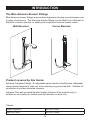
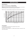
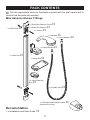
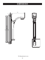
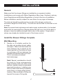
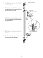
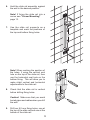
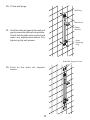
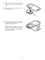
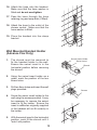
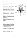
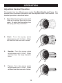
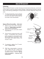
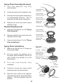
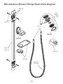
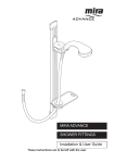
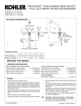
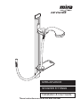
MIRA ADVANCE SHOWER FITTINGS Installation & User Guide These instructions are to be left with the user 1 the nation’s favourite for PLUMBING & HEATING SUPPLIES FREE SHIPPING SECURE PAYMENTS on all orders over £100 to mainland UK shop online with confidence FINANCE AVAILABLE PRICE MATCH spread the cost with low interest rates always get the best deals available we have H U G E R E D U C T I O N S ON THOUSANDS OF ITEMS Boilers Bathroom suites Radiators Kitchen sinks & taps Heating controls Showers Pipes & ittings Wet rooms Cylinders Towel warmers Fires Bathroom furniture Renewable energy & much more visit our website plumbnation.co.uk CALL US ON 0844 800 3460 CONTENTS Introduction...........................................................................................3 Speciication ......................................................................................... 4 Pack Contents ..................................................................................... 5 Dimensions........................................................................................... 6 Installation ............................................................................................ 7 Operation............................................................................................ 14 Maintenance ....................................................................................... 15 Fault Diagnosis................................................................................... 17 Spare parts ......................................................................................... 18 Customer Service ............................................................................... 20 If you experience any dificulty with the installation or operation of your new shower ittings, then please refer to "Fault Diagnosis", before contacting Kohler Mira Limited. Our telephone and fax numbers can be found on the back cover of this guide. 2 INTRODUCTION The Mira Advance Shower Fittings Mira Advance shower ittings are precision engineered to give a great shower over a range of pressures. The Advance shower ittings can be itted onto a lat wall or itted into a corner position, to satisfy and compliment various shower areas. Wall Mounted Corner Mounted Product covered by this Guide: Advance Complete Fittings - An adjustable spray handset, lexible hose, adjustable clamp bracket assembly, slide rail, hose retaining ring and soap dish. Suitable for connection to surface mounted showers. Advance Flex wall mounted handset holder (Advance Flex product only) is suitable for connection to surface mounted shower controls only. Patents Design Registraion 000738141-0006 000738141-0007 000738141-0008 3 SPECIFICATION Speciications Minimum maintained pressure: 6 kPa (0.06 Bar). Maximum maintained pressure: 500 kPa (5.0 bar). Warning! Exceeding the stated maximum maintained pressure could result in excessive spray forces and possible damage to the product. Pressure loss = Pressure difference between the inlet and outlet of the itting 26 24 Flow Rate (Litres/Minute) 22 Force 20 Start 18 16 Soothe 14 12 Eco 10 8 6 4 2 0 0 0.2 0.4 0.6 0.8 1.0 1.2 1.4 Pressure Loss (Bar) The Handset An adjustable spray handset with four different spray actions (Eco,Start, Soothe and Force). The shower hose terminates in a 1/2" BSP female thread for connection to the outlet of the shower. 4 PACK CONTENTS Tick the appropriate boxes to familiarize yourself with the part names and to conirm that the parts are included. Mira Advance Shower Fittings 2 x Slide Rail Support Covers 4 x Wall Plugs 2 x Slide Rail Supports 4 x Screws 1 x Handset 2 x Hose Washers 1 x Clamp Bracket 1 x Slide Rail 1 x Soap Dish 1 x Hose Retaining Ring 1 x Flexible Hose 1 x Wall Mounted Handset Holder (Advance Flex only) Documentation 1 x Installation and User Guide 5 DIMENSIONS 322 86 Flex Version 1000 658 600 23 56 176 All dimensions in mm 6 INSTALLATION General Make sure that the shower ittings are installed by a competent installer. Installations must comply with Water Regulations (Bye-Laws, Scotland), and any Local Regulations and Building Regulations in force at the time of installation. Before installation carefully inspect the new ixture for any signs of damage. The slide rail should be positioned to one side of the shower control at a convenient height for all the family. The slide rail can be ixed to a lat wall or into a corner. Note! To prevent back siphonage and water supply contamination, the handset must either be prevented from dropping below the spill over level of the bath or shower or have an additional single check valve in the system. Single check valves may already be installed as part of the shower control Install the Shower Fittings Complete Wall Mounting 1. Decide on a suitable position for the slide rail avoiding buried cables and pipes. Make sure that when the hose retaining ring is placed on the lowest position on the slide rail there is a minimum of 25 mm between the handset and bath/tray spill-over level. This is necessary to prevent back-siphonage. Note! Special consideration should be given to fixing arrangements when installing onto a dry lined, stud partition, shower cubicle or laminated panel wall structures. Installers may wish to obtain alternative proprietary cavity ixing, or choose other options, however, these methods of ixing are beyond the scope of this guide. 7 Minimum 25mm 2. Carefully remove the protective ilm from the slide rail. 3. Holding the clamp bracket, squeeze the sides together and push the clamp bracket onto the slide rail. Slide Rail Support Long Edge Clamp Bracket Note! It is important that you slide the shorter edge of the clamp bracket onto the slide rail. 4. Slide the hose retaining ring onto the slide rail. 5. Push the slide rail supports onto each end of the slide rail assembly. 8 Short Edge Hose Retaining Ring 6. Hold the slide rail assembly against the wall in the desired position. Note! If fixing the slide rail into a corner see "Corner Mounting" page 13. 7. Use the slide rail supports as a template and mark the positions of the top and bottom ixing holes. Note! When marking the position of the holes, if using the vertical oval hole on the top of the slide rail, then use the horizontal oval hole on the bottom ixing. This will allow you to make slight vertical and horizontal adjustments to the slide rail. 8. Check that the slide rail is vertical before drilling ixing holes. Caution! Make sure that you avoid buried pipes and cables when you drill the wall. 9. Drill two 8.0 mm ixing holes, one at the top of the slide rail and one at the bottom of the slide rail. 9 10. Fit the wall plugs. Wall Plug Wall Screw 11. Hold the slide rail against the wall and gently screw the slide rail into position. Check that the slide rail is vertical and make any adjustments before fully tightening the wall screws. Clamp Bracket Hose Retaining Ring Slide Rail Support Cover 12. Push on the slide rail support covers. 10 13. Align the notch on the soap dish with the recess on the hose retaining ring. 14. Push the soap dish onto the hose retaining ring. Notch Recess 15. To lock the soap dish into position twist the soap dish to the right or if preferred twist to the left. Note! If space is limited, you do not have to it the soap dish to the hose retaining ring, but the hose retaining ring must be itted. 11 16. Attach the hose onto the handset. Make sure that the hose washer is itted and do not overtighten. 17. Pass the hose through the hose retaining ring and soap dish (if itted). 18. Attach the hose to the outlet of the shower control. Make sure that the hose washer is itted. 19. Place the handset into the clamp bracket. Wall Mounted Handset Holder (Advance Flex Only) 1. The shroud must be removed to ix the handset holder to the wall. Ensure the swivel insert is in the horizontal position before removing the shroud. 2. Using the swivel insert holder as a guide, mark the position of the two screw holes. 3. Drill two 8mm holes and insert the wall plugs provided. 4. Screw the swivel insert holder to the wall using the screws provided. It may be necessary to remove the swivel insert to it the holder. Ensure the insert is reitted as originally supplied or the handset will not it correctly in the holder. 5. With the swivel insert in the horizontal position, push it the shroud until it 'locks' into position. 12 Swivel Insert Holder Swivel Insert Shroud Screws Corner Mounting 1. For corner mounting first follow instructions on pages 7 and 8, steps 1 to 6. 2. Hold the slide rail assembly against the wall in the desired position. 3. Use the slide rail supports as a template and mark the position of the two top ixing holes and the two bottom ixing holes. Note! Check that the slide rail supports are sitting on both walls before drilling ixing holes. 4. Drill two 8mm ixing holes at the top of the slide rail and two at the bottom of the slide rail. Caution! Make sure that you avoid buried pipes and cables when you drill the wall. 5. Fit the wall plugs. 6. Hold the slide rail against the wall and gently screw the slide rail into position. Check that the slide rail is vertical and make any adjustments before fully tightening the ixing screws. 7. Push on the slide rail support covers. 8. To complete the installation follow steps 13 to 19 on pages 11 and 12 13 Slide Rail Support Screw Screw Fixing Holes For Corner Position OPERATION Adjustable Handset Operation The handset has four different spray modes, Eco,Start, Soothe and Force. The handset has a combined checkvalve and low regulator itted in the handset. The handset operation is described below: 1. Eco: Water lows from the outer set of holes at a reduced low rate to save water. To select the Eco setting, turn the spray plate fully clockwise. 2. S t a r t : Tu r n t h e s p r a y p l a t e anticlockwise until it 'clicks'. Water will low from the outer set of holes. 3. Soothe: Turn the spray plate anticlockwise until it 'clicks'. Water will flow from the large diameter holes. 4. F o rce: Turn t he spray plat e anticlockwise until it 'clicks'. Water will low from the inner set of holes. 14 MAINTENANCE Cleaning Many household cleaners contain abrasives and chemical substances, and should not be used for cleaning plated or plastic ittings. These inishes should be cleaned with a mild washing up detergent or soap solution, and then wiped dry using a soft cloth. 1. To remove limescale, use your thumb or a soft cloth to wipe any limescale from the soft rubber nozzles and the front face of the showerhead. Spray Plate Assembly - Internal 1. 2. Remove the spray plate assembly. Refer to "Spray plate assembly removal and installation". Remove the inner and outer nozzle ring retainers. Outer Nozzel Ring Retainer 'O' Seals 3. Clean all the components with a stiff brush. If necessary use a plastic kettle descalent in accordance with the manufacturer's instructions. Flush thoroughly with water before the shower is used. Inner Nozzel Ring Retainer Spray Plate Assembly Adjuster Ring 4. If necessary replace the 'O' seals. Refer to Spare Parts. 5. Refit the components in reverse order. Make sure the 'O' seals, and the inner/outer nozzle ring retainers are itted correctly. Refer to "Spray plate assembly - removal and installation". 15 Spray Plate Assembly-Removal 1. Tu r n t h e a d j u s t e r r i n g f u l l y anticlockwise. 2. Unclip and remove the adjuster ring. 3. Unscrew the spray plate assembly in an anticlockwise direction. The 'O' seals will provide some resistance. 4. Remove the inner and outer nozzle retaining rings. Nozzle Ring Removal Handset Body Assembly Outer Nozzle Retaining Ring Inner Nozzle Retaining Ring Spray Plate Assembly Adjuster Ring 1. Carry out instructions 1 to 4 of "Spray Plate Removal". Outer Nozzle Retaining Ring 2. Remove both the inner and outer low capacity nozzle rings. Inner Nozzle Retaining Ring 3. Carry out instructions 1 to 6 of "Spray Plate Installation". Spray Plate Installation 1. 2. Make sure that the four 'O' seals are all correctly itted. Fit inner nozzle ring retainer on to the spray plate assembly and it the outer nozzle ring retainer on to the low divertor. 3. Tu r n t h e f l o w d i v e r t o r f u l l y clockwise. 4. Carefully screw the spray plate assembly onto the low divertor. 5. Align the inner teeth on the adjuster ring with the teeth on the handset low divertor. Clip the adjuster ring into position. 16 Spray Plate Assembly Spray Plate Assembly 'O' Seal Inner Nozzle Retaining Ring Outer Nozzle Retaining Ring 'O' Seals Flow Divertor Teeth Adjuster Ring Spray Plate Assembly Inner Teeth FAULT DIAGNOSIS The trouble shooting information tabled below gives details on what you can do as a user, should you encounter dificulties with the shower ittings whilst operating the shower. Before replacing any parts make sure that the underlying cause of the malfunction has been resolved. Malfunction No low or low low rate from the shower itting. Cause Remedy The spray plate assembly is blocked. Refer to the ‘Cleaning’ section. The hose is blocked or twisted. Clear blockage or replace the hose. Problem with the shower control. Refer to the Appliance Installation and User Guide. A small amount of water may be retained in the shower handset after the shower control has been turned off. This may drain over a few minutes. This is quite normal. Adjusting the position of the shower handset may reduce the draining time. Defective shower control. Refer to the Appliance Installation and User Guide. The shower temperature changes when the spray setting is adjusted. The spray plate assembly is blocked. Make sure that the spray plate assembly is clean. Refer to the ‘Cleaning’ section. If the malfunction persists refer to the Appliance Installation and User Guide. Hose does not it into the clamp bracket securely. Clamp bracket itted upside down in the slide rail. Remove the clamp bracket and rotate 180° and refit. Water dripping from the handset spray plate. 17 SPARES 450.08 Service Pack 'O' Seals - components identiied 'A' 632.73 Hose Washer 1603.098 Handset (White) 1603.102 Slide Rail Supports ( x 2 ) 1603.103 Soap Dish and Hose Retaining Ring 1603.104 Chrome Hose - 1.25m 1603.106 Chrome Hose - 2m (Flex Product) 1603.112 Mounting Pack 1603.113 Slide Rail 06 Satin 1603.114 Slide Rail 10 Satin 1603.115 Adjuster Ring - White 1603.116 Spray Plate Assembly 1603.120 Wall Mounted Handset Holder 1603.131 Adjuster Ring (Grey) 1603.132 Flex Clamp Bracket 1603.128 Handset - (Grey Adjuster Ring) 1644.124 Clamp Bracket 18 Mira Advance Shower Fittings Spare Parts Diagram 1603.102 8 .12 03 98 16 03.0 16 6 .11 03 16 1603.112 A 632.73 1603.115 1603.131 1644.124 1603.132 1603.113 1603.114 1603.120 1603.103 1603.104 1603.106 19 CUSTOMER SERVICE 1073000-W2-A (L12A) 20 © Kohler Mira Limited, February 2007