1
WinDriver USB v8.02 User’s Guide
Jungo Ltd
COPYRIGHT
Copyright ©1997 - 2006 Jungo Ltd. All Rights Reserved
Information in this document is subject to change without notice. The software
described in this document is furnished under a license agreement. The software
may be used, copied or distributed only in accordance with that agreement. No part
of this publication may be reproduced, stored in a retrieval system, or transmitted in
any form or any means, electronically or mechanically, including photocopying and
recording for any purpose without the written permission of Jungo Ltd.
Windows, Win32, Windows 98, Windows Me, Windows CE, Windows Mobile
5.0, Windows NT, Windows 2000, Windows XP and Windows Server 2003 are
trademarks of Microsoft Corp. WinDriver and KernelDriver are trademarks of Jungo.
Other brand and product names are trademarks or registered trademarks of their
respective holders.
1
Contents
Table of Contents
2
List of Figures
3
1
2
WinDriver Overview
1.1
Introduction to WinDriver . . . . . . . . . . . . . . . . . .
1.2
Background . . . . . . . . . . . . . . . . . . . . . . . . . .
1.2.1 The Challenge . . . . . . . . . . . . . . . . . . . .
1.2.2 The WinDriver Solution . . . . . . . . . . . . . . .
1.3
Conclusion . . . . . . . . . . . . . . . . . . . . . . . . . .
1.4
WinDriver Benefits . . . . . . . . . . . . . . . . . . . . . .
1.5
WinDriver Architecture . . . . . . . . . . . . . . . . . . . .
1.6
What Platforms Does WinDriver Support? . . . . . . . . . .
1.7
Limitations of the Different Evaluation Versions . . . . . . .
1.8
How Do I Develop My Driver with WinDriver? . . . . . . .
1.8.1 On Windows 98/Me/2000/XP/Server 2003 and Linux
1.8.2 On Windows CE . . . . . . . . . . . . . . . . . . .
1.9
What Does the WinDriver Toolkit Include? . . . . . . . . .
1.9.1 WinDriver Modules . . . . . . . . . . . . . . . . .
1.9.2 Utilities . . . . . . . . . . . . . . . . . . . . . . . .
1.9.3 WinDriver’s Specific Chipset Support . . . . . . . .
1.9.4 Samples . . . . . . . . . . . . . . . . . . . . . . .
1.10 Can I Distribute the Driver Created with WinDriver? . . . .
Understanding Device Drivers
2.1
Device Driver Overview . . . . . . . . . . . . . . . . .
2.2
Classification of Drivers According to Functionality . . .
2.2.1 Monolithic Drivers . . . . . . . . . . . . . . . .
2.2.2 Layered Drivers . . . . . . . . . . . . . . . . .
2.2.3 Miniport Drivers . . . . . . . . . . . . . . . . .
2.3
Classification of Drivers According to Operating Systems
2
.
.
.
.
.
.
.
.
.
.
.
.
.
.
.
.
.
.
.
.
.
.
.
.
.
.
.
.
.
.
.
.
.
.
.
.
.
.
.
.
.
.
.
.
.
.
.
.
.
.
.
.
.
.
.
.
.
.
.
.
.
.
.
.
.
.
.
.
.
.
.
.
.
4
4
5
5
6
6
7
8
8
9
9
9
10
10
10
11
12
12
12
.
.
.
.
.
.
.
.
.
.
.
.
.
.
.
.
.
.
.
.
.
.
.
.
13
13
14
14
15
15
16
.
.
.
.
.
.
.
.
.
.
CONTENTS
.
.
.
.
.
.
.
.
.
.
.
.
.
.
.
.
.
.
.
.
.
.
.
.
.
.
.
.
.
.
.
.
.
.
.
.
.
.
.
.
.
.
.
.
.
.
.
.
.
.
.
.
.
.
.
.
.
.
.
.
.
.
.
.
.
.
.
.
.
.
.
.
.
.
.
.
.
16
17
17
17
18
18
18
WinDriver USB Overview
3.1
Introduction to USB . . . . . . . . . . . . . . .
3.2
WinDriver USB Benefits . . . . . . . . . . . . .
3.3
USB Components . . . . . . . . . . . . . . . . .
3.4
Data Flow in USB Devices . . . . . . . . . . . .
3.5
USB Data Exchange . . . . . . . . . . . . . . .
3.6
USB Data Transfer Types . . . . . . . . . . . . .
3.6.1 Control Transfer . . . . . . . . . . . . .
3.6.2 Isochronous Transfer . . . . . . . . . . .
3.6.3 Interrupt Transfer . . . . . . . . . . . .
3.6.4 Bulk Transfer . . . . . . . . . . . . . . .
3.7
USB Configuration . . . . . . . . . . . . . . . .
3.8
WinDriver USB . . . . . . . . . . . . . . . . . .
3.9
WinDriver USB Architecture . . . . . . . . . . .
3.10 Which Drivers Can I Write with WinDriver USB?
.
.
.
.
.
.
.
.
.
.
.
.
.
.
.
.
.
.
.
.
.
.
.
.
.
.
.
.
.
.
.
.
.
.
.
.
.
.
.
.
.
.
.
.
.
.
.
.
.
.
.
.
.
.
.
.
.
.
.
.
.
.
.
.
.
.
.
.
.
.
.
.
.
.
.
.
.
.
.
.
.
.
.
.
.
.
.
.
.
.
.
.
.
.
.
.
.
.
.
.
.
.
.
.
.
.
.
.
.
.
.
.
.
.
.
.
.
.
.
.
.
.
.
.
.
.
.
.
.
.
.
.
.
.
.
.
.
.
.
.
20
20
21
22
22
24
25
25
25
26
26
27
29
30
31
2.4
2.5
2.6
3
4
2.3.1 WDM Drivers . . . . . . . .
2.3.2 VxD Drivers . . . . . . . . .
2.3.3 Unix Device Drivers . . . . .
2.3.4 Linux Device Drivers . . . .
The Entry Point of the Driver . . . . .
Associating the Hardware to the Driver
Communicating with Drivers . . . . .
3
.
.
.
.
.
.
.
.
.
.
.
. .
.
.
.
.
.
.
.
.
.
.
.
.
.
.
.
.
.
.
.
.
.
Installing WinDriver
4.1
System Requirements . . . . . . . . . . . . . . . . . . . . . . . . .
4.1.1 For Windows 98/Me . . . . . . . . . . . . . . . . . . . . .
4.1.2 For Windows 2000/XP/Server 2003 . . . . . . . . . . . . .
4.1.3 For Windows CE / Windows Mobile 5.0 . . . . . . . . . .
4.1.4 For Linux . . . . . . . . . . . . . . . . . . . . . . . . . . .
4.2
WinDriver Installation Process . . . . . . . . . . . . . . . . . . . .
4.2.1 Windows 98/Me/2000/XP/Server 2003 WinDriver
Installation Instructions . . . . . . . . . . . . . . . . . . .
4.2.2 Windows CE / Windows Mobile 5.0 WinDriver Installation
Instructions . . . . . . . . . . . . . . . . . . . . . . . . . .
4.2.2.1 Installing WinDriver CE when Building New
CE-Based Platforms . . . . . . . . . . . . . . .
4.2.2.2 Installing WinDriver CE when Developing
Applications for Windows CE / Windows Mobile
5.0 Computers . . . . . . . . . . . . . . . . . .
4.2.2.3 Windows CE Installation Note . . . . . . . . . .
4.2.3 Linux WinDriver Installation Instructions . . . . . . . . . .
4.2.3.1 Preparing the System for Installation . . . . . .
32
32
32
32
33
33
33
34
36
36
38
39
40
40
CONTENTS
4.3
4.4
4.5
5
6
7
4
4.2.3.2 Installation . . . . . . . . . . . . . .
4.2.3.3 Restricting Hardware Access on Linux
Upgrading Your Installation . . . . . . . . . . . . . . .
Checking Your Installation . . . . . . . . . . . . . . . .
4.4.1 On Your Windows and Linux Machines . . . . .
4.4.2 On Your Windows CE Machine . . . . . . . . .
Uninstalling WinDriver . . . . . . . . . . . . . . . . . .
4.5.1 On Windows 98/Me/2000/XP/Server 2003 . . .
4.5.2 On Linux . . . . . . . . . . . . . . . . . . . . .
. .
.
. .
. .
. .
. .
. .
. .
. .
.
.
.
.
.
.
.
.
.
.
.
.
.
.
.
.
.
.
.
.
.
.
.
.
.
.
.
Using DriverWizard
5.1
An Overview . . . . . . . . . . . . . . . . . . . . . . . . . . . .
5.2
DriverWizard Walkthrough . . . . . . . . . . . . . . . . . . . . .
5.3
DriverWizard Notes . . . . . . . . . . . . . . . . . . . . . . . . .
5.3.1 Logging WinDriver API Calls . . . . . . . . . . . . . . .
5.3.2 DriverWizard Logger . . . . . . . . . . . . . . . . . . .
5.3.3 Automatic Code Generation . . . . . . . . . . . . . . . .
5.3.3.1 Generating the Code . . . . . . . . . . . . . .
5.3.3.2 The Generated USB C Code . . . . . . . . . .
5.3.3.3 The Generated Visual Basic and Delphi Code .
5.3.3.4 The Generated C# and Visual Basic .NET Code
5.3.4 Compiling the Generated Code . . . . . . . . . . . . . .
5.3.4.1 Windows 98/Me/2000/XP/Server 2003 and
Windows CE Compilation: . . . . . . . . . . .
5.3.4.2 Linux Compilation . . . . . . . . . . . . . . .
.
.
.
.
.
.
.
.
.
41
43
43
44
44
44
45
45
47
.
.
.
.
.
.
.
.
.
.
.
48
48
49
60
60
60
60
60
60
61
61
61
.
.
61
61
Developing a Driver
6.1
Using the DriverWizard to Build a Device Driver . .
6.2
Writing the Device Driver Without the DriverWizard
6.2.1 Include the Required WinDriver Files . . . .
6.2.2 Write Your Code . . . . . . . . . . . . . . .
6.3
Developing Your Driver on Windows CE Platforms .
6.4
Developing in Visual Basic and Delphi . . . . . . . .
6.4.1 Using DriverWizard . . . . . . . . . . . . .
6.4.2 Samples . . . . . . . . . . . . . . . . . . .
6.4.3 Creating your Driver . . . . . . . . . . . . .
.
.
.
.
.
.
.
.
.
.
.
.
.
.
.
.
.
.
.
.
.
.
.
.
.
.
.
.
.
.
.
.
.
.
.
.
.
.
.
.
.
.
.
.
.
.
.
.
.
.
.
.
.
.
.
.
.
.
.
.
.
.
.
.
.
.
.
.
.
.
.
.
62
62
63
63
64
65
66
66
66
66
Debugging Drivers
7.1
User-Mode Debugging . . . . . . . . . . . . . .
7.2
Debug Monitor . . . . . . . . . . . . . . . . . .
7.2.1 Using Debug Monitor in Graphical Mode
7.2.2 Using Debug Monitor in Console Mode .
.
.
.
.
.
.
.
.
.
.
.
.
.
.
.
.
.
.
.
.
.
.
.
.
.
.
.
.
.
.
.
.
67
67
67
68
70
.
.
.
.
.
.
.
.
CONTENTS
5
7.2.2.1
Running wddebug on Windows, Windows CE
and Linux . . . . . . . . . . . . . . . . . . . . .
70
8
Enhanced Support for Specific Chipsets
8.1
Overview . . . . . . . . . . . . . . . . . . . . . . . . . . . . . . .
8.2
Developing a Driver Using the Enhanced Chipset Support . . . . .
72
72
73
9
USB Control Transfers
9.1
USB Control Transfers Overview . . . . . .
9.1.1 USB Data Exchange . . . . . . . . .
9.1.2 More About the Control Transfer . .
9.1.3 The Setup Packet . . . . . . . . . . .
9.1.4 USB Setup Packet Format . . . . . .
9.1.5 Standard Device Request Codes . . .
9.1.6 Setup Packet Example . . . . . . . .
9.2
Performing Control Transfers with WinDriver
9.2.1 Control Transfers with DriverWizard
9.2.2 Control Transfers with WinDriver API
.
.
.
.
.
.
.
.
.
.
.
.
.
.
.
.
.
.
.
.
.
.
.
.
.
.
.
.
.
.
74
74
74
75
76
77
78
78
80
80
82
10 Dynamically Loading Your Driver
10.1 Why Do You Need a Dynamically Loadable Driver? . . . . . .
10.2 Windows 98/Me/2000/XP/Server 2003 . . . . . . . . . . . . . .
10.2.1 Windows Driver Types . . . . . . . . . . . . . . . . . .
10.2.2 The WDREG Utility . . . . . . . . . . . . . . . . . . .
10.2.3 Dynamically Loading/Unloading windrvr6.sys INF Files
10.3 Linux . . . . . . . . . . . . . . . . . . . . . . . . . . . . . . .
10.4 Windows Mobile 5.0 . . . . . . . . . . . . . . . . . . . . . . .
.
.
.
.
.
.
.
.
.
.
.
.
.
.
83
83
83
83
84
85
86
87
.
.
.
.
.
.
.
.
.
.
88
88
89
89
90
93
93
94
95
98
98
.
.
.
.
.
.
.
.
.
.
.
.
.
.
.
.
.
.
.
.
.
.
.
.
.
.
.
.
.
.
.
.
.
.
.
.
.
.
.
.
.
.
.
.
.
.
.
.
.
.
.
.
.
.
.
.
.
.
.
.
.
.
.
.
.
.
.
.
.
.
.
.
.
.
.
.
.
.
.
.
.
.
.
.
.
.
.
.
.
11 Distributing Your Driver
11.1 Getting a Valid License for WinDriver . . . . . . . . . . . . . . .
11.2 Windows 98/Me/2000/XP/Server 2003 . . . . . . . . . . . . . . .
11.2.1 Preparing the Distribution Package . . . . . . . . . . . .
11.2.2 Installing Your Driver on the Target Computer . . . . . .
11.3 Creating an INF File . . . . . . . . . . . . . . . . . . . . . . . .
11.3.1 Why Should I Create an INF File? . . . . . . . . . . . .
11.3.2 How Do I Install an INF File When No Driver Exists? . .
11.3.3 How Do I Replace an Existing Driver Using the INF File?
11.4 Windows CE / Windows Mobile 5.0 . . . . . . . . . . . . . . . .
11.4.1 Distribution to New Windows CE Platforms . . . . . . .
11.4.2 Distribution to Windows CE / Windows Mobile 5.0
Computers . . . . . . . . . . . . . . . . . . . . . . . . .
11.5 Linux . . . . . . . . . . . . . . . . . . . . . . . . . . . . . . . .
11.5.1 WinDriver Kernel Module . . . . . . . . . . . . . . . . .
. 100
. 101
. 101
CONTENTS
6
11.5.2 User-Mode Hardware Control Application/Shared Objects . 102
11.5.3 Installation Script . . . . . . . . . . . . . . . . . . . . . . 102
12 WinDriver USB Device
12.1 WinDriver USB Device Overview . . . . . . . . . . . . . . . .
12.2 System and Hardware Requirements . . . . . . . . . . . . . . .
12.3 WinDriver Device Firmware (WDF) Directory Overview . . . .
12.3.1 The cypress Directory . . . . . . . . . . . . . . . . . .
12.3.2 The microchip Directory . . . . . . . . . . . . . . . . .
12.3.3 The philips Directory . . . . . . . . . . . . . . . . . .
12.3.4 The silabs Directory . . . . . . . . . . . . . . . . . . .
12.3.5 The WinDriver USB Device Firmware Libraries . . . .
12.3.6 Building the Sample Code . . . . . . . . . . . . . . . .
12.4 WinDriver USB Device Development Process . . . . . . . . . .
12.4.1 Define the Device USB Interface . . . . . . . . . . . .
12.4.1.1 EZ-USB Endpoint Buffers Configuration . .
12.4.2 Generate Device Firmware Code . . . . . . . . . . . .
12.4.3 Develop the Device Firmware . . . . . . . . . . . . . .
12.4.3.1 The Generated DriverWizard USB Device
Firmware Files . . . . . . . . . . . . . . . .
12.4.3.2 Build the Generated DriverWizard Firmware
12.4.3.3 Download the Firmware to the Device . . . .
12.4.4 Diagnose and Debug Your Hardware . . . . . . . . . .
12.4.5 Develop a USB Device Driver . . . . . . . . . . . . . .
.
.
.
.
.
.
.
.
.
.
.
.
.
.
.
.
.
.
.
.
.
.
.
.
.
.
.
.
103
103
106
107
107
108
111
113
115
115
117
117
123
124
126
.
.
.
.
.
.
.
.
.
.
127
129
130
131
131
A WinDriver USB PC Host API Reference
A.1 WinDriver USB (WDU) Library Overview . . . . . . . . . . . .
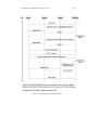
A.1.1 Calling Sequence for WinDriver USB . . . . . . . . . . .
A.1.2 Upgrading from the WD_xxx USB API to the WDU_xxx
API . . . . . . . . . . . . . . . . . . . . . . . . . . . . .
A.2 USB User Callback Functions . . . . . . . . . . . . . . . . . . .
A.2.1 WDU_ATTACH_CALLBACK() . . . . . . . . . . . . . .
A.2.2 WDU_DETACH_CALLBACK() . . . . . . . . . . . . . .
A.2.3 WDU_POWER_CHANGE_CALLBACK() . . . . . . . .
A.3 USB Functions . . . . . . . . . . . . . . . . . . . . . . . . . . .
A.3.1 WDU_Init() . . . . . . . . . . . . . . . . . . . . . . . . .
A.3.2 WDU_SetInterface() . . . . . . . . . . . . . . . . . . . .
A.3.3 WDU_GetDeviceAddr() . . . . . . . . . . . . . . . . . .
A.3.4 WDU_GetDeviceInfo() . . . . . . . . . . . . . . . . . . .
A.3.5 WDU_PutDeviceInfo() . . . . . . . . . . . . . . . . . . .
A.3.6 WDU_Uninit() . . . . . . . . . . . . . . . . . . . . . . .
A.3.7 WDU_Transfer() . . . . . . . . . . . . . . . . . . . . . .
A.3.8 WDU_Wakeup() . . . . . . . . . . . . . . . . . . . . . .
132
. 132
. 133
.
.
.
.
.
.
.
.
.
.
.
.
.
.
136
137
137
138
139
140
140
142
143
144
145
146
147
150
CONTENTS
A.4
A.5
A.6
A.3.9 WDU_TransferDefaultPipe() . . . . . . . .
A.3.10 WDU_TransferBulk() . . . . . . . . . . .
A.3.11 WDU_TransferIsoch() . . . . . . . . . . .
A.3.12 WDU_TransferInterrupt() . . . . . . . . .
A.3.13 WDU_HaltTransfer() . . . . . . . . . . . .
A.3.14 WDU_ResetPipe() . . . . . . . . . . . . .
A.3.15 WDU_ResetDevice() . . . . . . . . . . . .
A.3.16 WDU_GetLangIDs() . . . . . . . . . . . .
A.3.17 WDU_GetStringDesc() . . . . . . . . . . .
USB Structures . . . . . . . . . . . . . . . . . . .
A.4.1 WDU_MATCH_TABLE . . . . . . . . . .
A.4.2 WDU_EVENT_TABLE . . . . . . . . . .
A.4.3 WDU_DEVICE . . . . . . . . . . . . . .
A.4.4 WDU_CONFIGURATION . . . . . . . . .
A.4.5 WDU_INTERFACE . . . . . . . . . . . .
A.4.6 WDU_ALTERNATE_SETTING . . . . . .
A.4.7 WDU_DEVICE_DESCRIPTOR . . . . . .
A.4.8 WDU_CONFIGURATION_DESCRIPTOR
A.4.9 WDU_INTERFACE_DESCRIPTOR . . .
A.4.10 WDU_ENDPOINT_DESCRIPTOR . . . .
A.4.11 WDU_PIPE_INFO . . . . . . . . . . . . .
General WD_xxx Functions . . . . . . . . . . . .
A.5.1 Calling Sequence WinDriver – General Use
A.5.2 WD_Open() . . . . . . . . . . . . . . . . .
A.5.3 WD_Version() . . . . . . . . . . . . . . .
A.5.4 WD_Close() . . . . . . . . . . . . . . . .
A.5.5 WD_Debug() . . . . . . . . . . . . . . . .
A.5.6 WD_DebugAdd() . . . . . . . . . . . . . .
A.5.7 WD_DebugDump() . . . . . . . . . . . . .
A.5.8 WD_Sleep() . . . . . . . . . . . . . . . .
A.5.9 WD_License() . . . . . . . . . . . . . . .
User-Mode Utility Functions . . . . . . . . . . . .
A.6.1 Stat2Str() . . . . . . . . . . . . . . . . . .
A.6.2 get_os_type() . . . . . . . . . . . . . . . .
A.6.3 ThreadStart() . . . . . . . . . . . . . . . .
A.6.4 ThreadWait() . . . . . . . . . . . . . . . .
A.6.5 OsEventCreate() . . . . . . . . . . . . . .
A.6.6 OsEventClose() . . . . . . . . . . . . . . .
A.6.7 OsEventWait() . . . . . . . . . . . . . . .
A.6.8 OsEventSignal() . . . . . . . . . . . . . .
A.6.9 OsEventReset() . . . . . . . . . . . . . . .
A.6.10 OsMutexCreate() . . . . . . . . . . . . . .
7
.
.
.
.
.
.
.
.
.
.
.
.
.
.
.
.
.
.
.
.
.
.
.
.
.
.
.
.
.
.
.
.
.
.
.
.
.
.
.
.
.
.
.
.
.
.
.
.
.
.
.
.
.
.
.
.
.
.
.
.
.
.
.
.
.
.
.
.
.
.
.
.
.
.
.
.
.
.
.
.
.
.
.
.
.
.
.
.
.
.
.
.
.
.
.
.
.
.
.
.
.
.
.
.
.
.
.
.
.
.
.
.
.
.
.
.
.
.
.
.
.
.
.
.
.
.
.
.
.
.
.
.
.
.
.
.
.
.
.
.
.
.
.
.
.
.
.
.
.
.
.
.
.
.
.
.
.
.
.
.
.
.
.
.
.
.
.
.
.
.
.
.
.
.
.
.
.
.
.
.
.
.
.
.
.
.
.
.
.
.
.
.
.
.
.
.
.
.
.
.
.
.
.
.
.
.
.
.
.
.
.
.
.
.
.
.
.
.
.
.
.
.
.
.
.
.
.
.
.
.
.
.
.
.
.
.
.
.
.
.
.
.
.
.
.
.
.
.
.
.
.
.
.
.
.
.
.
.
.
.
.
.
.
.
.
.
.
.
.
.
.
.
.
.
.
.
.
.
.
.
.
.
.
.
.
.
.
.
.
.
.
.
.
.
.
.
.
.
.
.
.
.
.
.
.
.
.
.
.
.
.
.
.
.
.
.
.
.
.
.
.
.
.
.
.
.
.
.
.
.
.
.
.
.
.
.
.
.
.
.
.
.
.
.
.
.
.
.
.
.
.
.
.
.
.
.
.
.
.
.
.
.
.
.
.
.
.
.
.
.
.
.
.
.
.
.
.
.
151
152
153
154
155
156
157
158
160
162
163
163
164
164
165
165
166
167
167
168
168
169
169
171
172
174
175
177
179
181
183
186
186
187
188
189
190
191
192
193
194
195
CONTENTS
.
.
.
.
.
.
.
.
.
.
.
196
197
198
199
200
201
202
203
203
204
205
B USB Device – Cypress EZ-USB FX2LP CY7C68013A API Reference
B.1 Firmware Library API . . . . . . . . . . . . . . . . . . . . . . . .
B.1.1 Firmware Library Types . . . . . . . . . . . . . . . . . . .
B.1.1.1 EP_DIR Enumeration . . . . . . . . . . . . . .
B.1.1.2 EP_TYPE Enumeration . . . . . . . . . . . . .
B.1.1.3 EP_BUFFERING Enumeration . . . . . . . . .
B.1.2 Firmware Library Functions . . . . . . . . . . . . . . . . .
B.1.2.1 WDF_EP1INConfig() / WDF_EP1OUTConfig()
B.1.2.2 WDF_EP2Config / WDF_EP6Config() . . . . .
B.1.2.3 WDF_EP4Config / WDF_EP8Config() . . . . .
B.1.2.4 WDF_FIFOReset() . . . . . . . . . . . . . . . .
B.1.2.5 WDF_SkipOutPacket() . . . . . . . . . . . . . .
B.1.2.6 WDF_FIFOWrite() . . . . . . . . . . . . . . . .
B.1.2.7 WDF_FIFORead() . . . . . . . . . . . . . . . .
B.1.2.8 WDF_FIFOFull() . . . . . . . . . . . . . . . . .
B.1.2.9 WDF_FIFOEmpty() . . . . . . . . . . . . . . .
B.1.2.10 WDF_SetEPByteCount() . . . . . . . . . . . . .
B.1.2.11 WDF_GetEPByteCount() . . . . . . . . . . . . .
B.1.2.12 WDF_I2CInit() . . . . . . . . . . . . . . . . . .
B.1.2.13 WDF_SetDigitLed() . . . . . . . . . . . . . . .
B.1.2.14 WDF_I2CWrite() . . . . . . . . . . . . . . . . .
B.1.2.15 WDF_I2CRead() . . . . . . . . . . . . . . . . .
B.1.2.16 WDF_I2CWaitForEEPROMWrite() . . . . . . .
B.1.2.17 WDF_I2CGetStatus() . . . . . . . . . . . . . . .
B.1.2.18 WDF_I2CClearStatus() . . . . . . . . . . . . . .
B.2 Generated DriverWizard Firmware API . . . . . . . . . . . . . . .
B.2.1 WDF_Init() . . . . . . . . . . . . . . . . . . . . . . . . . .
B.2.2 WDF_Poll() . . . . . . . . . . . . . . . . . . . . . . . . . .
B.2.3 WDF_Suspend() . . . . . . . . . . . . . . . . . . . . . . .
B.2.4 WDF_Resume() . . . . . . . . . . . . . . . . . . . . . . .
B.2.5 WDF_GetDescriptor() . . . . . . . . . . . . . . . . . . . .
209
209
210
210
210
210
211
211
212
214
215
216
217
218
219
220
221
222
223
223
224
225
226
227
227
228
228
229
229
230
230
A.7
A.6.11 OsMutexClose() . . . . . . . . . . .
A.6.12 OsMutexLock() . . . . . . . . . . . .
A.6.13 OsMutexUnlock() . . . . . . . . . .
A.6.14 PrintDbgMessage() . . . . . . . . . .
A.6.15 WD_LogStart() . . . . . . . . . . . .
A.6.16 WD_LogStop() . . . . . . . . . . . .
A.6.17 WD_LogAdd() . . . . . . . . . . . .
WinDriver Status Codes . . . . . . . . . . .
A.7.1 Introduction . . . . . . . . . . . . .
A.7.2 Status Codes Returned by WinDriver
A.7.3 Status Codes Returned by USBD . .
8
.
.
.
.
.
.
.
.
.
.
.
.
.
.
.
.
.
.
.
.
.
.
.
.
.
.
.
.
.
.
.
.
.
.
.
.
.
.
.
.
.
.
.
.
.
.
.
.
.
.
.
.
.
.
.
.
.
.
.
.
.
.
.
.
.
.
.
.
.
.
.
.
.
.
.
.
.
.
.
.
.
.
.
.
.
.
.
.
.
.
.
.
.
.
.
.
.
.
.
.
.
.
.
.
.
.
.
.
.
.
.
.
.
.
.
.
.
.
.
.
.
CONTENTS
B.2.6
B.2.7
B.2.8
B.2.9
B.2.10
B.2.11
B.2.12
B.2.13
9
WDF_SetConfiguration() .
WDF_GetConfiguration()
WDF_SetInterface() . . .
WDF_GetInterface() . . .
WDF_GetStatus() . . . . .
WDF_ClearFeature() . . .
WDF_SetFeature() . . . .
WDF_VendorCmnd() . . .
.
.
.
.
.
.
.
.
.
.
.
.
.
.
.
.
.
.
.
.
.
.
.
.
.
.
.
.
.
.
.
.
.
.
.
.
.
.
.
.
.
.
.
.
.
.
.
.
.
.
.
.
.
.
.
.
.
.
.
.
.
.
.
.
.
.
.
.
.
.
.
.
.
.
.
.
.
.
.
.
.
.
.
.
.
.
.
.
.
.
.
.
.
.
.
.
.
.
.
.
.
.
.
.
.
.
.
.
.
.
.
.
.
.
.
.
.
.
.
.
.
.
.
.
.
.
.
.
.
.
.
.
.
.
.
.
.
.
.
.
.
.
.
.
231
232
233
234
235
235
236
236
C USB Device – Microchip PIC18F4550 API Reference
C.1 Firmware Library API . . . . . . . . . . . . . . . . . . . . .
C.1.1 Firmware Library Types . . . . . . . . . . . . . . . .
C.1.1.1 EP_DIR Enumeration . . . . . . . . . . .
C.1.1.2 EP_TYPE Enumeration . . . . . . . . . .
C.1.1.3 WDF_TRIGGER_OPTIONS Enumeration
C.1.1.4 BD_STAT Union . . . . . . . . . . . . . .
C.1.1.5 BDT Union . . . . . . . . . . . . . . . . .
C.1.1.6 WORD Union . . . . . . . . . . . . . . .
C.1.1.7 DWORD Union . . . . . . . . . . . . . .
C.1.1.8 POINTER Union . . . . . . . . . . . . . .
C.1.1.9 USB_DEVICE_STATUS Union . . . . . .
C.1.1.10 CTRL_TRF_SETUP Union . . . . . . . .
C.1.1.11 EP_DATA Structure . . . . . . . . . . . . .
C.1.1.12 USB_DEVICE_CTX Structure . . . . . . .
C.1.2 wdf_microchip_lib.h Functions and Macros . . . . .
C.1.2.1 WDF_EPConfig() . . . . . . . . . . . . . .
C.1.2.2 WDF_EPWrite() . . . . . . . . . . . . . .
C.1.2.3 WDF_EPWriteRom() . . . . . . . . . . . .
C.1.2.4 WDF_EPWriteNoCopy() . . . . . . . . . .
C.1.2.5 WDF_EPRead() . . . . . . . . . . . . . . .
C.1.2.6 WDF_IsEPStall() . . . . . . . . . . . . . .
C.1.2.7 WDF_IsEPBusy() . . . . . . . . . . . . . .
C.1.2.8 WDF_IsEPDataReady() . . . . . . . . . .
C.1.2.9 WDF_TriggerWriteTransfer() . . . . . . .
C.1.2.10 WDF_TriggerOptionWriteTransfer() . . . .
C.1.2.11 WDF_TriggerReadTransfer() . . . . . . . .
C.1.2.12 WDF_TriggerOptionReadTransfer() . . . .
C.1.2.13 WDF_TriggerReadTransferNoCopy() . . .
C.1.2.14 WDF_GetReadBytesCount() . . . . . . . .
C.1.2.15 WDF_DisableEP1to15() . . . . . . . . . .
C.1.2.16 WDF_DisableEP() . . . . . . . . . . . . .
C.1.3 wdf_usb9.h Functions . . . . . . . . . . . . . . . . .
C.1.3.1 WDF_USBCheckStdRequest() . . . . . . .
.
.
.
.
.
.
.
.
.
.
.
.
.
.
.
.
.
.
.
.
.
.
.
.
.
.
.
.
.
.
.
.
.
.
.
.
.
.
.
.
.
.
.
.
.
.
.
.
.
.
.
.
.
.
.
.
.
.
.
.
.
.
.
.
.
.
.
.
.
.
.
.
.
.
.
.
.
.
.
.
.
.
.
.
.
.
.
.
.
.
.
.
.
.
.
.
.
.
.
237
237
238
238
238
238
239
240
240
241
241
242
242
245
245
246
246
248
249
250
251
252
253
254
255
256
257
258
259
260
261
261
262
263
CONTENTS
C.2
C.3
C.4
10
Mass Storage Firmware Library API . . . . . . . . . .
C.2.1 WDF_MSD_Init() . . . . . . . . . . . . . . .
C.2.2 WDF_MSD_USBCheckMSDRequest() . . . .
C.2.3 WDF_MSD_ProcessIO() . . . . . . . . . . . .
Generated DriverWizard Firmware API . . . . . . . .
C.3.1 WDF_Init() . . . . . . . . . . . . . . . . . . .
C.3.2 WDF_Poll() . . . . . . . . . . . . . . . . . . .
C.3.3 WDF_SOFHandler() . . . . . . . . . . . . . .
C.3.4 WDF_Suspend() . . . . . . . . . . . . . . . .
C.3.5 WDF_Resume() . . . . . . . . . . . . . . . .
C.3.6 WDF_ErrorHandler() . . . . . . . . . . . . . .
C.3.7 WDF_SetConfiguration() . . . . . . . . . . . .
C.3.8 WDF_SetInterface() . . . . . . . . . . . . . .
C.3.9 WDF_GetInterface() . . . . . . . . . . . . . .
C.3.10 WDF_VendorCmnd() . . . . . . . . . . . . . .
C.3.11 WDF_ClearFeature() . . . . . . . . . . . . . .
C.3.12 WDF_SetFeature() . . . . . . . . . . . . . . .
Generated DriverWizard Mass Storage Firmware API .
C.4.1 Generated Mass Storage Firmware Types . . .
C.4.1.1 WDF_DISK_STATUS Enumeration
C.4.1.2 DISK_STATE Union . . . . . . . .
C.4.2 Generated Mass Storage Firmware Functions .
C.4.2.1 WDF_DISK_MediaInitialize() . . .
C.4.2.2 WDF_DISK_SectorRead() . . . . .
C.4.2.3 WDF_DISK_SectorWrite() . . . . .
C.4.2.4 WDF_DISK_Detect() . . . . . . . .
C.4.2.5 WDF_DISK_IsWriteProtected() . .
C.4.2.6 WDF_DISK_GetCapacity() . . . .
D USB Device – Philips PDIUSBD12 API Reference
D.1 Firmware Library API . . . . . . . . . . . . . . . .
D.1.1 Firmware Library Types . . . . . . . . . . .
D.1.1.1 WDF_ENDPOINTS Enumeration
D.1.1.2 D12_MODES Enumeration . . .
D.1.1.3 DMA_DIRECTION Enumeration
D.1.2 Firmware Library Functions . . . . . . . . .
D.1.2.1 WDF_Exit() . . . . . . . . . . . .
D.1.2.2 WDF_ConnectUSB() . . . . . . .
D.1.2.3 WDF_DisconnectUSB() . . . . .
D.1.2.4 WDF_ReconnectUSB() . . . . . .
D.1.2.5 WDF_EnableAllEP() . . . . . . .
D.1.2.6 WDF_DisableEP1AND2() . . . .
D.1.2.7 WDF_StallEP0() . . . . . . . . .
.
.
.
.
.
.
.
.
.
.
.
.
.
.
.
.
.
.
.
.
.
.
.
.
.
.
.
.
.
.
.
.
.
.
.
.
.
.
.
.
.
.
.
.
.
.
.
.
.
.
.
.
.
.
.
.
.
.
.
.
.
.
.
.
.
.
.
.
.
.
.
.
.
.
.
.
.
.
.
.
.
.
.
.
.
.
.
.
.
.
.
.
.
.
.
.
.
.
.
.
.
.
.
.
.
.
.
.
.
.
.
.
.
.
.
.
.
.
.
.
.
.
.
.
.
.
.
.
.
.
.
.
.
.
.
.
.
.
.
.
.
.
.
.
.
.
.
.
.
.
.
.
.
.
.
.
.
.
.
.
.
.
.
.
.
.
.
.
.
.
.
.
.
.
.
.
.
.
.
.
.
.
.
.
.
.
.
.
.
.
.
.
.
.
.
.
.
.
.
.
.
.
.
.
.
.
.
.
.
264
265
266
267
268
268
269
269
270
270
271
272
273
274
275
276
276
277
277
277
278
279
279
280
281
282
282
283
.
.
.
.
.
.
.
.
.
.
.
.
.
.
.
.
.
.
.
.
.
.
.
.
.
.
.
.
.
.
.
.
.
.
.
.
.
.
.
.
.
.
.
.
.
.
.
.
.
.
.
.
.
.
.
.
.
.
.
.
.
.
.
.
.
.
.
.
.
.
.
.
.
.
.
.
.
.
.
.
.
.
.
.
.
.
.
.
.
.
.
284
284
285
285
285
285
286
286
287
288
289
290
290
291
CONTENTS
.
.
.
.
.
.
.
.
.
.
.
.
.
.
.
.
.
.
.
.
.
.
.
.
.
.
.
.
.
.
.
.
.
.
.
.
.
.
.
.
.
.
.
.
.
.
.
.
.
.
.
.
.
.
.
.
.
.
.
.
.
.
.
292
293
294
295
296
297
297
298
299
300
301
302
302
303
303
304
304
305
305
306
306
E USB Device – Silicon Laboratories C8051F320 and C8051F340 API
Reference
E.1
Firmware Library API . . . . . . . . . . . . . . . . . . . . . .
E.1.1 wdf_silabs_lib.h Types . . . . . . . . . . . . . . . . . .
E.1.1.1 EP_DIR Enumeration . . . . . . . . . . . .
E.1.1.2 EP_TYPE Enumeration . . . . . . . . . . .
E.1.1.3 EP_BUFFERING Enumeration . . . . . . .
E.1.1.4 EP_SPLIT Enumeration . . . . . . . . . . .
E.1.2 c8051f320.h Types and General Definitions . . . . . . .
E.1.2.1 Endpoint Address Definitions . . . . . . . .
E.1.2.2 Endpoint State Definitions . . . . . . . . . .
E.1.2.3 EP_INT_HANDLER Function Pointer . . .
E.1.2.4 EP0_COMMAND Structure . . . . . . . . .
E.1.2.5 EP_STATUS Structure . . . . . . . . . . . .
E.1.2.6 PEP_STATUS Structure Pointer . . . . . . .
E.1.2.7 IF_STATUS Structure . . . . . . . . . . . . .
E.1.2.8 PIF_STATUS Structure Pointer . . . . . . .
E.1.3 Firmware Library Functions . . . . . . . . . . . . . . .
E.1.3.1 WDF_EPINConfig() . . . . . . . . . . . . .
E.1.3.2 WDF_EPOUTConfig() . . . . . . . . . . . .
E.1.3.3 WDF_HaltEndpoint() . . . . . . . . . . . . .
.
.
.
.
.
.
.
.
.
.
.
.
.
.
.
.
.
.
.
.
.
.
.
.
.
.
.
.
.
.
.
.
.
.
.
.
.
.
308
308
309
309
309
309
310
310
310
310
311
311
312
312
312
313
313
313
314
316
D.2
D.1.2.8 WDF_EPoutFull() . .
D.1.2.9 WDF_EPinFull() . . .
D.1.2.10 WDF_EPWrite() . . .
D.1.2.11 WDF_EPRead() . . . .
D.1.2.12 WDF_DMASetup() . .
D.1.2.13 WDF_DMARunning()
D.1.2.14 WDF_DMAStop() . .
D.1.2.15 WDF_SetLEDStatus()
D.1.2.16 WDF_GetKeyStatus()
D.1.2.17 outportb() . . . . . . .
D.1.2.18 inportb() . . . . . . . .
Generated DriverWizard Firmware API .
D.2.1 WDF_Init() . . . . . . . . . . . .
D.2.2 WDF_Uninit() . . . . . . . . . .
D.2.3 WDF_SuspendChange() . . . . .
D.2.4 WDF_Poll() . . . . . . . . . . . .
D.2.5 WDF_BusReset() . . . . . . . . .
D.2.6 WDF_SetConfiguration() . . . . .
D.2.7 WDF_SetInterface() . . . . . . .
D.2.8 WDF_GetInterface() . . . . . . .
D.2.9 WDF_VendorRequest() . . . . . .
11
.
.
.
.
.
.
.
.
.
.
.
.
.
.
.
.
.
.
.
.
.
.
.
.
.
.
.
.
.
.
.
.
.
.
.
.
.
.
.
.
.
.
.
.
.
.
.
.
.
.
.
.
.
.
.
.
.
.
.
.
.
.
.
.
.
.
.
.
.
.
.
.
.
.
.
.
.
.
.
.
.
.
.
.
.
.
.
.
.
.
.
.
.
.
.
.
.
.
.
.
.
.
.
.
.
.
.
.
.
.
.
.
.
.
.
.
.
.
.
.
.
.
.
.
.
.
.
.
.
.
.
.
.
.
.
.
.
.
.
.
.
.
.
.
.
.
.
.
.
.
.
.
.
.
.
.
.
.
.
.
.
.
.
.
.
.
.
.
.
.
.
.
.
.
.
.
.
.
.
.
.
.
.
.
.
.
.
.
.
.
.
.
.
.
.
.
.
.
.
.
.
.
.
.
.
.
.
.
.
.
.
.
.
.
.
.
.
.
.
.
.
.
.
.
.
.
.
.
.
.
.
CONTENTS
E.2
E.1.3.4 WDF_EnableEndpoint() .
E.1.3.5 WDF_SetEPByteCount() .
E.1.3.6 WDF_GetEPByteCount() .
E.1.3.7 WDF_FIFOClear() . . . .
E.1.3.8 WDF_FIFOFull() . . . . .
E.1.3.9 WDF_FIFOEmpty() . . .
E.1.3.10 WDF_FIFOWrite() . . . .
E.1.3.11 WDF_FIFORead() . . . .
E.1.3.12 WDF_GetEPStatus() . . .
Generated DriverWizard Firmware API . . .
E.2.1 WDF_USBReset() . . . . . . . . . .
E.2.2 WDF_SetAddressRequest() . . . . .
E.2.3 WDF_SetFeatureRequest() . . . . . .
E.2.4 WDF_ClearFeatureRequest() . . . . .
E.2.5 WDF_SetConfigurationRequest() . .
E.2.6 WDF_SetDescriptorRequest() . . . .
E.2.7 WDF_SetInterfaceRequest() . . . . .
E.2.8 WDF_GetStatusRequest() . . . . . .
E.2.9 WDF_GetDescriptorRequest() . . . .
E.2.10 WDF_GetConfigurationRequest() . .
E.2.11 WDF_GetInterfaceRequest() . . . . .
F Troubleshooting and Support
12
.
.
.
.
.
.
.
.
.
.
.
.
.
.
.
.
.
.
.
.
.
.
.
.
.
.
.
.
.
.
.
.
.
.
.
.
.
.
.
.
.
.
.
.
.
.
.
.
.
.
.
.
.
.
.
.
.
.
.
.
.
.
.
.
.
.
.
.
.
.
.
.
.
.
.
.
.
.
.
.
.
.
.
.
.
.
.
.
.
.
.
.
.
.
.
.
.
.
.
.
.
.
.
.
.
.
.
.
.
.
.
.
.
.
.
.
.
.
.
.
.
.
.
.
.
.
.
.
.
.
.
.
.
.
.
.
.
.
.
.
.
.
.
.
.
.
.
.
.
.
.
.
.
.
.
.
.
.
.
.
.
.
.
.
.
.
.
.
.
.
.
.
.
.
.
.
.
.
.
.
.
.
.
.
.
.
.
.
.
.
.
.
.
.
.
.
.
.
.
.
.
.
.
.
.
.
.
.
.
.
.
.
.
.
.
.
.
.
.
.
.
.
.
.
.
.
.
.
.
.
.
.
.
.
.
.
.
.
.
.
.
.
.
.
.
.
.
.
.
.
.
.
317
318
319
320
321
322
323
324
325
326
326
327
327
328
328
329
329
330
330
331
331
332
G Evaluation Version Limitations
333
G.1 Windows 98/Me/2000/XP/Server 2003 . . . . . . . . . . . . . . . . 333
G.2 Windows CE . . . . . . . . . . . . . . . . . . . . . . . . . . . . . 333
G.3 Linux . . . . . . . . . . . . . . . . . . . . . . . . . . . . . . . . . 334
H Purchasing WinDriver
335
I
Distributing Your Driver – Legal Issues
336
J
Additional Documentation
337
List of Figures
1.1
WinDriver Architecture . . . . . . . . . . . . . . . . . . . . . . . . .
8
2.1
2.2
2.3
Monolithic Drivers . . . . . . . . . . . . . . . . . . . . . . . . . . .
Layered Drivers . . . . . . . . . . . . . . . . . . . . . . . . . . . . .
Miniport Drivers . . . . . . . . . . . . . . . . . . . . . . . . . . . .
14
15
16
3.1
3.2
3.3
3.4
USB Endpoints . . . . . . .
USB Pipes . . . . . . . . . .
Device Descriptors . . . . .
WinDriver USB Architecture
23
24
27
31
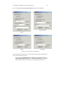
5.1
5.2
5.3
5.4
5.5
5.6
5.7
5.8
5.9
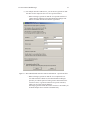
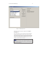
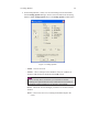
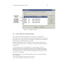
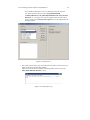
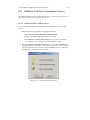
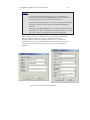
Select Your Device . . . . . . . . . . . . . . . . . . . . . . . . . . .
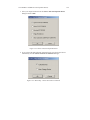
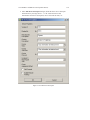
DriverWizard INF File Information . . . . . . . . . . . . . . . . . . .
DriverWizard Multi-Interface INF File Information – Specific Interface
DriverWizard Multi-Interface INF File Information – Composite Device
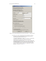
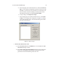
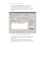
Select Device Interface . . . . . . . . . . . . . . . . . . . . . . . . .
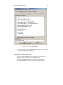
Test Your Device . . . . . . . . . . . . . . . . . . . . . . . . . . . .
USB Requests List . . . . . . . . . . . . . . . . . . . . . . . . . . .
Write to Pipe . . . . . . . . . . . . . . . . . . . . . . . . . . . . . .
Code Generation Options . . . . . . . . . . . . . . . . . . . . . . . .
50
51
52
53
54
55
56
57
58
7.1
7.2
Start Debug Monitor . . . . . . . . . . . . . . . . . . . . . . . . . .
Debug Options . . . . . . . . . . . . . . . . . . . . . . . . . . . . .
68
69
9.1
9.2
9.3
9.4
9.5
USB Data Exchange
USB Read and Write
Custom Request . . .
Request List . . . . .
USB Request Log . .
75
76
80
81
81
.
.
.
.
.
.
.
.
.
.
.
.
.
.
.
.
.
.
.
.
.
.
.
.
.
.
.
.
.
.
.
.
.
.
.
.
.
.
.
.
.
.
.
.
.
.
.
.
.
.
.
.
.
.
.
.
.
.
.
.
.
.
.
.
.
.
.
.
.
.
.
.
.
.
.
.
.
.
.
.
.
.
.
.
.
.
.
.
.
.
.
.
.
.
.
.
.
.
.
.
.
.
.
.
.
.
.
.
.
.
.
.
.
.
.
.
.
.
.
.
.
.
.
.
.
.
.
.
.
.
.
.
.
.
.
.
.
.
.
.
.
.
.
.
.
.
.
.
.
.
.
.
.
.
.
.
.
.
.
.
.
.
.
.
.
.
.
.
.
.
.
.
.
.
.
.
.
.
.
.
.
.
.
.
.
.
.
.
.
.
.
.
.
.
.
.
.
.
.
.
.
.
.
.
.
.
.
.
.
.
.
.
.
.
.
.
.
.
12.1 Create Device Firmware Project . . . . . . . . . . . . . . . . . . . . 117
13
LIST OF FIGURES
12.2 Choose Your Development Board . . . . . . . . . . . .
12.3 Microchip – Choose Your Device Function . . . . . . .
12.4 Edit Device Descriptor . . . . . . . . . . . . . . . . . .
12.5 Configure Your Device . . . . . . . . . . . . . . . . . .
12.6 Define Interfaces and Endpoints . . . . . . . . . . . . .
12.7 Philips PDIUSBD12 – Define Main Endpoint Pipes . . .
12.8 Microchip PIC18F4550 Mass Storage – Edit Inquiry Info
12.9 EZ-USB Endpoint Buffers . . . . . . . . . . . . . . . .
12.10Firmware Code Generation . . . . . . . . . . . . . . . .
14
.
.
.
.
.
.
.
.
.
.
.
.
.
.
.
.
.
.
.
.
.
.
.
.
.
.
.
.
.
.
.
.
.
.
.
.
.
.
.
.
.
.
.
.
.
.
.
.
.
.
.
.
.
.
.
.
.
.
.
.
.
.
.
118
118
119
120
121
122
123
124
125
A.1 WinDriver USB Calling Sequence . . . . . . . . . . . . . . . . . . . 134
A.2 WinDriver USB Structures . . . . . . . . . . . . . . . . . . . . . . . 162
A.3 WinDriver API Calling Sequence . . . . . . . . . . . . . . . . . . . . 169
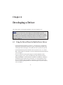
Chapter 1
WinDriver Overview
In this chapter you will explore the uses of WinDriver, and learn the basic steps of
creating your driver.
The WinDriver USB Device toolkit, for development of USB device firmware code, is
outlined separately in Chapter 12.
NOTE
This manual outlines WinDriver’s support for USB devices. WinDriver also
supports development for PCI/PCMCIA/CardBus/ISA/EISA/CompactPCI/PCI
Express devices. For detailed information regarding WinDriver’s support
for these buses, please refer to the WinDriver Product Line page on our
web-site (http://www.jungo.com/windriver.html) and to the WinDriver
PCI/PCMCIA/CardBus/ISA/EISA/CompactPCI/PCI Express User’s Manual, which
is available on-line at:
http://www.jungo.com/support/support_windriver.html.
Support for USB on Windows NT 4.0 is provided in a separate tool-kit – see our
WinDriver USB for NT web-page: http://www.jungo.com/wdusb_nt.html.
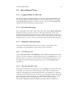
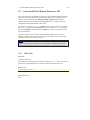
1.1 Introduction to WinDriver
WinDriver is a development toolkit that dramatically simplifies the difficult task
of creating device drivers and hardware access applications. WinDriver includes
a wizard and code generation features that automatically detect your hardware and
generate the driver to access it from your application. The driver and application you
develop using WinDriver is source code compatible between all supported operating
15
1.2 Background
16
systems (WinDriver currently supports Windows 98/Me/2000/XP/Server2003,
Windows CE.NET/Windows Mobile 5.0 and Linux). The driver is binary compatible
between Windows 98/Me/2000/XP/Server 2003. WinDriver provides a complete
solution for creating high-performance drivers.
Don’t let the size of this manual fool you. WinDriver makes developing device
drivers an easy task that takes hours instead of months. Most of this manual deals
with the features that WinDriver offers to the advanced user. However, most
developers will find that reading this chapter and glancing through the DriverWizard
and function reference chapters is all they need to successfully write their driver.
WinDriver supports development for all USB chipsets. Enhanced support is offered
for Cypress, Microchip, Philips, Texas Instruments and Silicon Laboratories USB
chipsets, as outlined in Chapter 8 of the manual.
Visit Jungo’s web site at http://www.jungo.com for the latest news about
WinDriver and other driver development tools that Jungo offers.
1.2 Background
1.2.1 The Challenge
In protected operating systems such as Windows and Linux, a programmer cannot
access hardware directly from the application level (user mode), where development
work is usually done. Hardware can only be accessed from within the operating
system itself (kernel mode or Ring-0), utilizing software modules called device
drivers. In order to access a custom hardware device from the application level, a
programmer must do the following:
• Learn the internals of the operating system he is working on (Windows
98/Me/2000/XP/Server2003, Windows CE.NET/Windows Mobile 5.0 and
Linux).
• Learn how to write a device driver.
• Learn new tools for developing/debugging in kernel mode (DDK, ETK,
DDI/DKI).
• Write the kernel-mode device driver that does the basic hardware input/output.
• Write the application in user mode that accesses the hardware through the
device driver written in kernel mode.
• Repeat the first four steps for each new operating system on which the code
should run.
1.3 Conclusion
17
1.2.2 The WinDriver Solution
Easy Development: WinDriver enables Windows 98 / Me / 2000 / XP / Server2003,
Windows CE.NET / Windows Mobile 5.0 and Linux programmers to create
USB based device drivers in an extremely short time. WinDriver allows
you to create your driver in the familiar user-mode environment, using
MSDEV/Visual C/C++, MSDEV .NET, Borland C++ Builder, Borland Delphi,
Visual Basic 6.0, MS eMbedded Visual C++, MS Platform Builder C++, GCC,
or any other appropriate compiler. You do not need to have any device driver
knowledge, nor do you have to be familiar with operating system internals,
kernel programming, the DDK, ETK or DDI/DKI.
Cross Platform: The driver created with WinDriver will run on Windows
98/Me/2000/XP/Server2003, Windows CE.NET/Windows Mobile 5.0 and
Linux. In other words – write it once, run it on many platforms.
Friendly Wizards: DriverWizard (included) is a graphical diagnostics tool that lets
you view the device’s resources and test the communication with the hardware
with just a few mouse clicks, before writing a single line of code. Once the
device is operating to your satisfaction, DriverWizard creates the skeletal driver
source code, giving access functions to all the resources on the hardware.
Kernel-Mode Performance: WinDriver’s API is optimized for performance.
1.3 Conclusion
Using WinDriver, a developer need only do the following to create an application that
accesses the custom hardware:
• Start DriverWizard and detect the hardware and its resources.
• Automatically generate the device driver code from within DriverWizard,
or use one of the WinDriver samples as the basis for the application (see
Chapter 8 for an overview of WinDriver’s enhanced support for specific
chipsets).
• Modify the user-mode application, as needed, using the generated/sample
functions to implement the desired functionality for your application.
Your hardware access application will run on all the supported platforms: Windows
98/Me/2000/XP/Server2003, Windows CE.NET/Windows Mobile 5.0 and Linux
– just re-compile the code for the target platform. (The code is binary compatible
between Windows 98/Me/2000/XP/Server 2003 platforms, so there is no need to
rebuild the code when porting the driver between these operating systems.)
1.4 WinDriver Benefits
18
1.4 WinDriver Benefits
• Easy user-mode driver development.
• Friendly DriverWizard allows hardware diagnostics without writing a single
line of code.
• Automatically generates the driver code for the project in C, C#, Visual Basic
.NET, Delphi (Pascal) or Visual Basic.
• Supports any USB device, regardless of manufacturer.
• Enhanced support for Cypress, Microchip, Philips, Texas Instruments and
Silicon Laboratories chipsets frees the developer from the need to study the
hardware’s specification.
• Applications are binary-compatible across Windows 98 / Me / 2000 / XP /
Server 2003.
• Applications are source code compatible across Windows 98 / Me / 2000 / XP /
Server2003, Windows CE.NET / Windows Mobile 5.0 and Linux.
• Can be used with common development environments, including
MSDEV/Visual C/C++, MSDEV .NET, Borland C++ Builder, Borland Delphi,
Visual Basic 6.0, MS eMbedded Visual C++, MS Platform Builder C++, GCC,
or any other appropriate compiler.
• No DDK, ETK, DDI or any system-level programming knowledge required.
• Supports multiple CPUs.
• Includes dynamic driver loader.
• Comprehensive documentation and help files.
• Detailed examples in C, C#, Visual Basic .NET, Delphi and Visual Basic 6.0.
• WHQL certifiable driver (Windows).
• Two months of free technical support.
• No run-time fees or royalties.
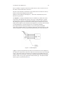
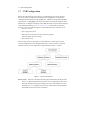
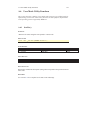
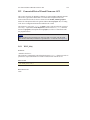
1.5 WinDriver Architecture
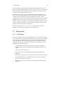
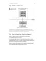
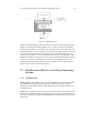
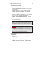
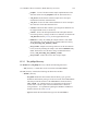
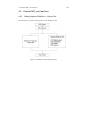
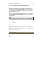
1.5 WinDriver Architecture
Figure 1.1: WinDriver Architecture
For hardware access, your application calls one of the WinDriver user-mode
functions. The user-mode function calls the WinDriver kernel, which accesses the
hardware for you through the native calls of the operating system.
1.6 What Platforms Does WinDriver Support?
WinDriver supports Windows 98/Me/2000/XP/Server2003, Windows
CE.NET/Windows Mobile 5.0 and Linux.
The same source code will run on all supported platforms – simply re-compile
it for the target platform. The source code is binary compatible across Windows
98/Me/2000/XP/Server 2003, so executables created with WinDriver can be ported
between these operating systems without re-compilation.
Even if your code is meant only for one of the supported operating systems, using
WinDriver will give you the flexibility to move your driver to another operating
system in the future without needing to change your code.
19
1.7 Limitations of the Different Evaluation Versions
20
1.7 Limitations of the Different Evaluation Versions
All the evaluation versions of the WinDriver USB Host toolkit are full featured. No
functions are limited or crippled in any way. The evaluation version of WinDriver
varies from the registered version in the following ways:
• Each time WinDriver is activated, an Un-registered message appears.
• When using the DriverWizard, a dialogue box with a message stating that an
evaluation version is being run appears on every interaction with the hardware.
• In the Linux and CE versions, the driver will remain operational for 60
minutes, after which time it must be restarted.
• The Windows evaluation version expires 30 days from the date of installation.
For more details please refer to appendix G.
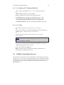
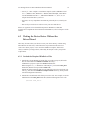
1.8 How Do I Develop My Driver with WinDriver?
1.8.1 On Windows 98/Me/2000/XP/Server 2003 and Linux
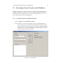
1. Start DriverWizard and use it to diagnose your hardware – see details in
Chapter 5.
2. Let DriverWizard generate skeletal code for your driver, or use one of the
WinDriver samples as the basis for your driver application (see Chapter [8]
for details regarding WinDriver’s enhanced support for specific chipsets).
3. Modify the generated/sample code to suit your application’s needs.
4. Run and debug your driver.
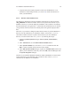
NOTE
The code generated by DriverWizard is a diagnostics program that contains
functions that perform data transfers on the device’s pipes, send requests to the
control pipe, change the active alternate setting, reset pipes, and more.
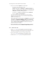
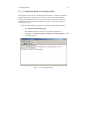
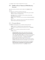
1.9 What Does the WinDriver Toolkit Include?
21
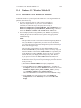
1.8.2 On Windows CE
1. Plug your hardware into a Windows host machine.
2. Diagnose your hardware using DriverWizard.
3. Let DriverWizard generate your driver’s skeletal code.
4. Modify this code using eMbedded Visual C++ to meet your specific needs. If
you are using Platform Builder, activate it and insert the generated *.pbp into
your workspace.
5. Test and debug your code and hardware from the CE emulation running on the
host machine.
1.9 What Does the WinDriver Toolkit Include?
• A printed version of this manual
• Two months of free technical support (Phone/Fax/Email)
• WinDriver modules
• The WinDriver CD
– Utilities
– Chipset support APIs
– Sample files
1.9.1 WinDriver Modules
• WinDriver (WinDriver/include) – the general purpose hardware access toolkit.
The main files here are:
– windrvr.h: Declarations and definitions of WinDriver’s basic API.
– wdu_lib.h: Declarations and definitions of the WinDriver USB (WDU)
library, which provides convenient wrapper USB APIs.
– windrvr_int_thread.h: Declarations of convenient wrapper functions to
simplify interrupt handling.
– windrvr_events.h: Declarations of APIs for handling and Plug-and-Play
and power management events.
– utils.h: Declarations of general utility functions.
1.9 What Does the WinDriver Toolkit Include?
22
– status_strings.h: Declarations of API for converting WinDriver status
codes to descriptive error strings.
• DriverWizard (WinDriver/wizard/wdwizard) – a graphical tool that diagnoses
your hardware and enables you to easily generate code for your driver (refer to
Chapter 5 for details).
• Graphical Debugger (WinDriver/util/wddebug_gui) – a graphical debugging
tool that collects information about your driver as it runs.
WinDriver also includes a console version of this program
(WinDriver/util/wddebug), which can be used on platforms that have no GUI
support, such as Windows CE .
For details regarding the Debug Monitor, refer to section 7.2.
• WinDriver distribution package (WinDriver/redist) – the files you include in
the driver distribution to customers.
• This manual – the full WinDriver manual (this document), in different formats,
can be found under the WinDriver/docs directory.
1.9.2 Utilities
• usb_diag.exe (WinDriver/util/usb_diag.exe) – enables the user to view the
resources of connected USB devices and communicate with the devices –
transfer data to/from the device, set the active alternate setting, reset pipes, etc.
On Windows 98/Me/2000/XP/Server 2003 the program identifies all devices
that have been registered to work with WinDriver using an INF file. On the
other supported operating systems the program identifies all USB devices
connected to the target platform.
• pci_dump.exe (WinDriver/util/pci_dump.exe) – used to obtain a dump of the
PCI configuration registers of the installed PCI cards.
The Windows CE version also includes:
• \REDIST\... \X86EMU\WINDRVR_CE_EMU.DLL: DLL that
communicates with the WinDriver kernel – for the x86 HPC emulation mode
of Windows CE.
• \REDIST\... \X86EMU\WINDRVR_CE_EMU.LIB: an import library that
is used to link with WinDriver applications that are compiled for the x86 HPC
emulation mode of Windows CE.
1.10 Can I Distribute the Driver Created with WinDriver?
23
1.9.3 WinDriver’s Specific Chipset Support
WinDriver provides custom wrapper APIs and sample code for major USB chipsets
(see Chapter 8), including for the following chipsets:
• Cypress EZ-USB – WinDriver/cypress
• Microchip PIC18F4550 – WinDriver/microchip/pic18f4550
• Philips PDIUSBD12 – WinDriver/pdiusbd12
• Texas Instruments TUSB3410, TUSB3210, TUSB2136 and TUSB5052 –
WinDriver/ti
• Silicon Laboratories C8051F320 USB – WinDriver/silabs
1.9.4 Samples
In addition to the samples provided for specific chipsets [1.9.3], WinDriver includes
a variety of samples that demonstrate how to use WinDriver’s API to communicate
with your device and perform various driver tasks.
• C samples: found under the WinDriver/samples directory.
These samples also include the source code for the utilities listed above [1.9.2].
• .NET C# and Visual Basic .NET samples (Windows): found under the
WinDriver\csharp.net and WinDriver\vb.net directories (respectively).
• Delphi (Pascal) samples (Windows) WinDriver\delphi\samples directory.
• Visual Basic samples (Windows): found under the WinDriver\vb\samples
directory.
1.10 Can I Distribute the Driver Created with
WinDriver?
Yes. WinDriver is purchased as a development toolkit, and any device driver created
using WinDriver may be distributed, royalties free, in as many copies as you wish.
See the license agreement (WinDriver/docs/license.pdf) for more details.
Chapter 2
Understanding Device Drivers
This chapter provides you with a general introduction to device drivers and takes you
through the structural elements of a device driver.
NOTE
Using WinDriver, you do not need to familiarize yourself with the internal workings
of driver development. As explained in Chapter 1 of the manual, WinDriver enables
you to communicate with your hardware and develop a driver for your device from
the user mode, using only WinDriver’s simple APIs, without any need for driver or
kernel development knowledge.
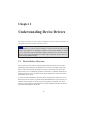
2.1 Device Driver Overview
Device drivers are the software segments that provides an interface between the
operating system and the specific hardware devices such as terminals, disks, tape
drives, video cards and network media. The device driver brings the device into
and out of service, sets hardware parameters in the device, transmits data from the
kernel to the device, receives data from the device and passes it back to the kernel,
and handles device errors.
A driver acts like a translator between the device and programs that use the device.
Each device has its own set of specialized commands that only its driver knows. In
contrast, most programs access devices by using generic commands. The driver,
therefore, accepts generic commands from a program and then translates them into
specialized commands for the device.
24
2.2 Classification of Drivers According to Functionality
2.2 Classification of Drivers According to
Functionality
There are numerous driver types, differing in their functionality. This subsection
briefly describes three of the most common driver types.
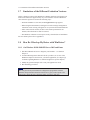
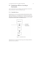
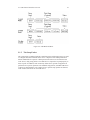
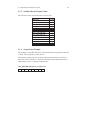
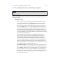
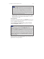
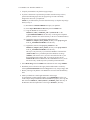
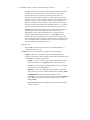
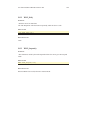
2.2.1 Monolithic Drivers
Monolithic drivers are device drivers that embody all the functionality needed to
support a hardware device. A monolithic driver is accessed by one or more user
applications, and directly drives a hardware device. The driver communicates with
the application through I/O control commands (IOCTLs) and drives the hardware
using calls to the different DDK, ETK, DDI/DKI functions.
Figure 2.1: Monolithic Drivers
Monolithic drivers are supported in all operating systems including all Windows
platforms and all Unix platforms.
25
2.2 Classification of Drivers According to Functionality
26
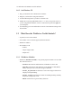
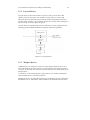
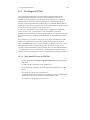
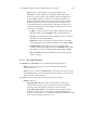
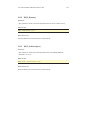
2.2.2 Layered Drivers
Layered drivers are device drivers that are part of a stack of device drivers that
together process an I/O request. An example of a layered driver is a driver that
intercepts calls to the disk and encrypts/decrypts all data being transferred to/from
the disk. In this example, a driver would be hooked on to the top of the existing driver
and would only do the encryption/decryption.
Layered drivers are sometimes also known as filter drivers, and are supported in all
operating systems including all Windows platforms and all Unix platforms.
Figure 2.2: Layered Drivers
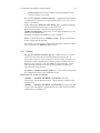
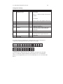
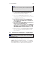
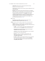
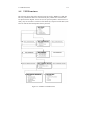
2.2.3 Miniport Drivers
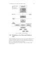
A Miniport driver is an add-on to a class driver that supports miniport drivers. It is
used so the miniport driver does not have to implement all of the functions required
of a driver for that class. The class driver provides the basic class functionality for the
miniport driver.
A class driver is a driver that supports a group of devices of common functionality,
such as all HID devices or all network devices.
Miniport drivers are also called miniclass drivers or minidrivers, and are supported in
the Windows NT (or 2000) family, namely Windows NT/2000/XP and Server 2003.
2.3 Classification of Drivers According to Operating Systems
27
Figure 2.3: Miniport Drivers
Windows NT/2000/XP/Server 2003 provide several driver classes (called ports) that
handle the common functionality of their class. It is then up to the user to add only
the functionality that has to do with the inner workings of the specific hardware. The
NDIS miniport driver is one example of such a driver. The NDIS miniport framework
is used to create network drivers that hook up to NT’s communication stacks, and
are therefore accessible to common communication calls used by applications. The
Windows NT kernel provides drivers for the various communication stacks and other
code that is common to communication cards. Due to the NDIS framework, the
network card developer does not have to write all of this code, only the code that is
specific to the network card he is developing.
2.3 Classification of Drivers According to Operating
Systems
2.3.1 WDM Drivers
WDM (Windows Driver Model) drivers are kernel-mode drivers within the Windows
NT and Windows 98 operating system families. Windows NT family includes
Windows NT/2000/XP/Server 2003, and Windows 98 family includes Windows 98
and Windows Me.
WDM works by channeling some of the work of the device driver into portions of the
code that are integrated into the operating system. These portions of code handle all
of the low-level buffer management, including DMA and Plug and Play (Pnp) device
enumeration.
2.3 Classification of Drivers According to Operating Systems
28
WDM drivers are PnP drivers that support power management protocols, and include
monolithic drivers, layered drivers and miniport drivers.
2.3.2 VxD Drivers
VxD drivers are Windows 95/98/Me Virtual Device Drivers, often called VxDs
because the file names end with the .vxd extension. VxD drivers are typically
monolithic in nature. They provide direct access to hardware and privileged operating
system functions. VxD drivers can be stacked or layered in any fashion, but the driver
structure itself does not impose any layering.
2.3.3 Unix Device Drivers
In the classic Unix driver model, devices belong to one of three categories: character
(char) devices, block devices and network devices. Drivers that implement these
devices are correspondingly known as char drivers, block drivers or network drivers.
Under Unix, drivers are code units linked into the kernel that run in privileged kernel
mode. Generally, driver code runs on behalf of a user-mode application. Access to
Unix drivers from user-mode applications is provided via the file system. In other
words, devices appear to the applications as special device files that can be opened.
Unix device drivers are either layered or monolithic drivers. A monolithic driver can
be perceived as a one-layer layered driver.
2.3.4 Linux Device Drivers
Linux device drivers are based on the classic Unix device driver model. In addition,
Linux introduces some new characteristics.
Under Linux, a block device can be accessed like a character device, as in Unix, but
also has a block-oriented interface that is invisible to the user or application.
Traditionally, under Unix, device drivers are linked with the kernel, and the system is
brought down and restarted after installing a new driver. Linux introduces the concept
of a dynamically loadable driver called a module. Linux modules can be loaded or
removed dynamically without requiring the system to be shut down. A Linux driver
can be written so that it is statically linked or written in a modular form that allows
it to be dynamically loaded. This makes Linux memory usage very efficient because
modules can be written to probe for their own hardware and unload themselves if they
cannot find the hardware they are looking for.
Like Unix device drivers, Linux device drivers are either layered or monolithic
drivers.
2.4 The Entry Point of the Driver
29
2.4 The Entry Point of the Driver
Every device driver must have one main entry point, like the main() function in a
C console application. This entry point is called DriverEntry() in Windows and
init_module() in Linux. When the operating system loads the device driver, this
driver entry procedure is called.
There is some global initialization that every driver needs to perform only once when
it is loaded for the first time. This global initialization is the responsibility of the
DriverEntry()/init_module() routine. The entry function also registers which
driver callbacks will be called by the operating system. These driver callbacks are
operating system requests for services from the driver. In Windows, these callbacks
are called dispatch routines, and in Linux they are called file operations. Each
registered callback is called by the operating system as a result of some criteria, such
as disconnection of hardware, for example.
2.5 Associating the Hardware to the Driver
Operating systems differ in how they link a device to its driver.
In Windows, the link is performed by the INF file, which registers the device to work
with the driver. This association is performed before the DriverEntry() routine is
called. The operating system recognizes the device, looks up in its database which
INF file is associated with the device, and according to the INF file, calls the driver’s
entry point.
In Linux, the link between a device and its driver is defined in the init_module()
routine. The init_module() routine includes a callback which states what hardware
the driver is designated to handle. The operating system calls the driver’s entry point,
based on the definition in the code.
2.6 Communicating with Drivers
A driver can create an instance, thus enabling an application to open a handle to the
driver through which the application can communicate with it.
The applications communicate with the drivers using a file access API (Application
Program Interface). Applications open a handle to the driver using CreateFile()
call (in Windows), or open() call (in Linux) with the name of the device as the file
name. In order to read from and write to the device, the application calls ReadFile()
and WriteFile() (in Windows), or read(), write() in Linux.
2.6 Communicating with Drivers
30
Sending requests is accomplished using an I/O control call, called
DeviceIoControl() (in Windows), and ioctl() in Linux. In this I/O control call,
the application specifies:
• The device to which the call is made (by providing the device’s handle).
• An IOCTL code that describes which function this device should perform.
• A buffer with the data on which the request should be performed.
The IOCTL code is a number that the driver and the requester agree upon for a
common task.
The data passed between the driver and the application is encapsulated into a
structure. In Windows, this structure is called an I/O Request Packet (IRP), and is
encapsulated by the I/O Manager. This structure is passed on to the device driver,
which may modify it and pass it down to other device drivers.
Chapter 3
WinDriver USB Overview
This chapter explores the basic characteristics of the Universal Serial Bus (USB) and
introduces WinDriver USB’s features and architecture.
NOTE
The references to the WinDriver USB toolkit in this chapter relate to the standard
WinDriver USB toolkit for development of USB host drivers.
The WinDriver USB Device toolkit, designed for development of USB device
firmware, is discussed separately in Chapter 12.
3.1 Introduction to USB
USB (Universal Serial Bus) is an industry standard extension to the PC architecture
for attaching peripherals to the computer. It was originally developed in 1995 by
leading PC and telecommunication industry companies, such as Intel, Compaq,
Microsoft and NEC. USB was developed to meet several needs, among them the
needs for an inexpensive and widespread connectivity solution for peripherals in
general and for computer telephony integration in particular, an easy-to-use and
flexible method of reconfiguring the PC, and a solution for adding a large number
of external peripherals. The USB standard meets these needs.
The USB specification allows for the connection of a maximum of 127 peripheral
devices (including hubs) to the system, either on the same port or on different ports.
USB also supports Plug and Play installation and hot swapping.
The USB 1.1 standard supports both isochronous and asynchronous data transfers
and has dual speed data transfer: 1.5 Mb/s (megabits per second) for low-speed USB
31
3.2 WinDriver USB Benefits
32
devices and 12 Mb/s for high-speed USB devices (much faster than the original serial
port). Cables connecting the device to the PC can be up to five meters (16.4 feet)
long. USB includes built-in power distribution for low power devices and can provide
limited power (up to 500 mA of current) to devices attached on the bus.
The USB 2.0 standard supports a signalling rate of 480 Mb/s, known as
”high-speed”, which is 40 times faster than the USB 1.1 full-speed transfer rate.
USB 2.0 is fully forward- and backward-compatible with USB 1.1 and uses existing
cables and connectors.
USB 2.0 supports connections with PC peripherals that provide expanded
functionality and require wider bandwidth. In addition, it can handle a larger number
of peripherals simultaneously.
USB 2.0 enhances the user’s experience of many applications, including interactive
gaming, broadband Internet access, desktop and Web publishing, Internet services
and conferencing.
Because of its benefits (described also in section 3.2 below), USB is currently
enjoying broad market acceptance.
3.2 WinDriver USB Benefits
This section describes the main benefits of the USB standard and the WinDriver USB
toolkit, which supports this standard:
• External connection, maximizing ease of use
• Self identifying peripherals supporting automatic mapping of function to driver
and configuration
• Dynamically attachable and re-configurable peripherals
• Suitable for device bandwidths ranging from a few Kb/s to hundreds of Mb/s
• Supports isochronous as well as asynchronous transfer types over the same set
of wires
• Supports simultaneous operation of many devices (multiple connections)
• Supports a data transfer rate of up to 480 Mb/s (high-speed) for USB 2.0 (for
the operating systems that officially support this standard) and up to 12 Mb/s
(full-speed) for USB 1.1
• Guaranteed bandwidth and low latencies; appropriate for telephony, audio, etc.
(isochronous transfer may use almost the entire bus bandwidth)
• Flexibility: supports a wide range of packet sizes and a wide range of data
transfer rates
3.3 USB Components
33
• Robustness: built-in error handling mechanism and dynamic insertion and
removal of devices with no delay observed by the user
• Synergy with PC industry; Uses commodity technologies
• Optimized for integration in peripheral and host hardware
• Low-cost implementation, therefore suitable for development of low-cost
peripherals
• Low-cost cables and connectors
• Built-in power management and distribution
3.3 USB Components
The Universal Serial bus is comprised of the following primary components:
USB Host: The USB host platform is where the USB host controller is installed and
where the client software/device driver runs. The USB Host Controller is the
interface between the host and the USB peripherals. The host is responsible
for detecting the insertion and removal of USB devices, managing the control
and data flow between the host and the devices, providing power to attached
devices and more.
USB Hub: A USB device that allows multiple USB devices to attach to a single
USB port on a USB host. Hubs on the back plane of the hosts are called root
hubs. Other hubs are called external hubs.
USB Function: A USB device that can transmit or receive data or control
information over the bus and that provides a function. A function is typically
implemented as a separate peripheral device that plugs into a port on a hub
using a cable. However, it is also possible to create a compound device, which
is a physical package that implements multiple functions and an embedded hub
with a single USB cable. A compound device appears to the host as a hub with
one or more non-removable USB devices, which may have ports to support the
connection of external devices.
3.4 Data Flow in USB Devices
During the operation of a USB device, the host can initiate a flow of data between the
client software and the device.
Data can be transferred between the host and only one device at a time (peer to peer
communication). However, two hosts cannot communicate directly, nor can two USB
3.4 Data Flow in USB Devices
34
devices (with the exception of On-The-Go (OTG) devices, where one device acts as
the master (host) and the other as the slave.)
The data on the USB bus is transferred via pipes that run between software memory
buffers on the host and endpoints on the device.
Data flow on the USB bus is half-duplex, i.e. data can be transmitted only in one
direction at a given time.
An endpoint is a uniquely identifiable entity on a USB device, which is the source
or terminus of the data that flows from or to the device. Each USB device, logical
or physical, has a collection of independent endpoints. The three USB speeds (low,
full and high) all support one bi-directional control endpoint (endpoint zero) and 15
unidirectional endpoints. Each unidirectional endpoint can be used for either inbound
or outbound transfers, so theoretically there are 30 supported endpoints.
Each endpoint has the following attributes: bus access frequency, bandwidth
requirement, endpoint number, error handling mechanism, maximum packet size that
can be transmitted or received, transfer type and direction (into or out of the device).
Figure 3.1: USB Endpoints
A pipe is a logical component that represents an association between an endpoint on
the USB device and software on the host. Data is moved to and from a device through
a pipe. A pipe can be either a stream pipe or a message pipe, depending on the type
of data transfer used in the pipe. Stream pipes handle interrupt, bulk and isochronous
transfers, while message pipes support the control transfer type. The different USB
transfer types are discussed below [3.6].
3.5 USB Data Exchange
35
3.5 USB Data Exchange
The USB standard supports two kinds of data exchange between a host and a device:
functional data exchange and control exchange.
Functional data exchange is used to move data to and from the device. There are
three types of data transfers: bulk, interrupt and isochronous.
Control exchange is used to determine device identification and configuration
requirements and to configure a device, and can also be used for other
device-specific purposes, including control of other pipes on the device.
Control exchange takes place via a control pipe, mainly the default Pipe 0,
which always exists. The control transfer consists of a setup stage (in which
a setup packet is sent from the host to the device), an optional data stage and a
status stage.
Figure 3.2 below depicts a USB device with one bi-directional control pipe (endpoint)
and six functional data transfer pipes (endpoints), as identified by WinDriver’s
DriverWizard utility (discussed in Chapter 5).
Figure 3.2: USB Pipes
3.6 USB Data Transfer Types
36
More information on how to implement the control transfer by sending setup packets
can be found in Chapter 9.
3.6 USB Data Transfer Types
The USB device (function) communicates with the host by transferring data through
a pipe between a memory buffer on the host and an endpoint on the device. USB
supports four different transfer types. A type is selected for a specific endpoint
according to the requirements of the device and the software. The transfer type of a
specific endpoint is determined in the endpoint descriptor.
The USB specification provides for the following data transfer types:
3.6.1 Control Transfer
Control Transfer is mainly intended to support configuration, command and status
operations between the software on the host and the device.
This transfer type is used for low-, full- and high-speed devices.
Each USB device has at least one control pipe (default pipe), which provides access
to the configuration, status and control information.
Control transfer is bursty, non-periodic communication.
The control pipe is bi-directional – i.e. data can flow in both directions.
Control transfer has a robust error detection, recovery and retransmission mechanism
and retries are made without the involvement of the driver.
The maximum packet size for control endpoints can be only 8 bytes for low-speed
devices; 8, 16, 32, or 64 bytes for full-speed devices; and only 64 bytes for
high-speed devices.
3.6.2 Isochronous Transfer
Isochronous Transfer is most commonly used for time-dependent information, such
as multimedia streams and telephony.
This transfer type can be used by full-speed and high-speed devices, but not by
low-speed devices.
Isochronous transfer is periodic and continuous.
3.6 USB Data Transfer Types
37
The isochronous pipe is unidirectional, i.e. a certain endpoint can either transmit
or receive information. Bi-directional isochronous communication requires two
isochronous pipes, one in each direction.
USB guarantees the isochronous transfer access to the USB bandwidth (i.e. it
reserves the required amount of bytes of the USB frame) with bounded latency, and
guarantees the data transfer rate through the pipe, unless there is less data transmitted.
Since timeliness is more important than correctness in this type of transfer, no
retries are made in case of error in the data transfer. However, the data receiver can
determine that an error occurred on the bus.
3.6.3 Interrupt Transfer
Interrupt Transfer is intended for devices that send and receive small amounts of data
infrequently or in an asynchronous time frame.
This transfer type can be used for low-, full- and high-speed devices.
Interrupt transfer type guarantees a maximum service period and that delivery will be
re-attempted in the next period if there is an error on the bus.
The interrupt pipe, like the isochronous pipe, is unidirectional and periodical.
The maximum packet size for interrupt endpoints can be 8 bytes or less for low-speed
devices; 64 bytes or less for full-speed devices; and 1,024 bytes or less for high-speed
devices.
3.6.4 Bulk Transfer
Bulk Transfer is typically used for devices that transfer large amounts of non-time
sensitive data, and that can use any available bandwidth, such as printers and
scanners.
This transfer type can be used by full-speed and high-speed devices, but not by
low-speed devices.
Bulk transfer is non-periodic, large packet, bursty communication.
Bulk transfer allows access to the bus on an "as-available" basis, guarantees the data
transfer but not the latency, and provides an error check mechanism with retries
attempts. If part of the USB bandwidth is not being used for other transfers, the
system will use it for bulk transfer.
Like the other stream pipes (isochronous and interrupt), the bulk pipe is also
unidirectional, so bi-directional transfers require two endpoints.
The maximum packet size for bulk endpoints can be 8, 16, 32, or 64 bytes for
full-speed devices, and 512 bytes for high-speed devices.
3.7 USB Configuration
38
3.7 USB Configuration
Before the USB function (or functions, in a compound device) can be operated,
the device must be configured. The host does the configuring by acquiring the
configuration information from the USB device. USB devices report their attributes
by descriptors. A descriptor is the defined structure and format in which the data is
transferred. A complete description of the USB descriptors can be found in Chapter 9
of the USB Specification (see http://www.usb.org for the full specification).
It is best to view the USB descriptors as a hierarchical structure with four levels:
• The Device level
• The Configuration level
• The Interface level (this level may include an optional
sub-level called Alternate Setting)
• The Endpoint level
There is only one device descriptor for each USB device. Each device has one
or more configurations, each configuration has one or more interfaces, and each
interface has zero or more endpoints, as demonstrated in Figure 3.3 below.
Figure 3.3: Device Descriptors
Device Level: The device descriptor includes general information about the USB
device, i.e. global information for all of the device configurations. The device
descriptor identifies, among other things, the device class (HID device, hub,
locator device, etc.), subclass, protocol code, vendor ID, device ID and more.
Each USB device has one device descriptor.
3.7 USB Configuration
39
Configuration Level: A USB device has one or more configuration descriptors.
Each descriptor identifies the number of interfaces grouped in the configuration
and the power attributes of the configuration (such as self-powered, remote
wakeup, maximum power consumption and more). Only one configuration
can be loaded at a given time. For example, an ISDN adapter might have two
different configurations, one that presents it with a single interface of 128 Kb/s
and a second that presents it with two interfaces of 64 Kb/s each.
Interface Level: The interface is a related set of endpoints that present a
specific functionality or feature of the device. Each interface may operate
independently. The interface descriptor describes the number of the interface,
the number of endpoints used by this interface and the interface-specific class,
subclass and protocol values when the interface operates independently.
In addition, an interface may have alternate settings. The alternate settings
allow the endpoints or their characteristics to be varied after the device is
configured.
Endpoint Level: The lowest level is the endpoint descriptor, which provides the
host with information regarding the endpoint’s data transfer type and maximum
packet size. For isochronous endpoints, the maximum packet size is used
to reserve the required bus time for the data transfer – i.e. the bandwidth.
Other endpoint attributes are its bus access frequency, endpoint number, error
handling mechanism and direction.
The same endpoint can have different properties (and consequently different
uses) in different alternate settings.
Seems complicated? Not at all! WinDriver automates the USB configuration process.
The included DriverWizard utility [5] and USB diagnostics application scan the USB
bus, detect all USB devices and their configurations, interfaces, alternate settings
and endpoints, and enable you to pick the desired configuration before starting driver
development.
WinDriver identifies the endpoint transfer type as determined in the endpoint
descriptor. The driver created with WinDriver contains all configuration information
acquired at this early stage.
3.8 WinDriver USB
40
3.8 WinDriver USB
WinDriver USB enables developers to quickly develop high-performance drivers for
USB-based devices, without having to learn the USB specifications or the operating
system’s internals.
Using WinDriver USB, developers can create USB drivers without having to use
the operating system’s development kits (such as the Windows DDK); In addition,
Windows developers do not need to familiarize themselves with Microsoft’s Win32
Driver Module (WDM).
The driver code developed with WinDriver USB is binary compatible across
the supported Windows platforms – Windows 98/Me/2000/XP/Server 2003 –
and source code compatible across all supported operating systems – Windows
98/Me/2000/XP/Server2003, Windows CE.NET/Windows Mobile 5.0 and Linux.
For an up-to-date list of supported operating systems, visit Jungo’s web site at:
http://www.jungo.com.
WinDriver USB is a generic tool kit that supports all USB devices from all vendors
and with all types of configurations.
WinDriver USB encapsulates the USB specification and architecture, letting you
focus on your application logic. WinDriver USB features the graphical DriverWizard
utility [5], which enables you to easily detect your hardware, view its configuration
information, and test it, before writing a single line of code: DriverWizard first lets
you choose the desired configuration, interface and alternate setting combination,
using a friendly graphical user interface. After detecting and configuring your USB
device, you can proceed to test the communication with the device – perform data
transfers on the pipes, send control requests, reset the pipes, etc. – in order to ensure
that all your hardware resources function as expected.
After your hardware is diagnosed, you can use DriverWizard to automatically
generate your device driver source code in C, C#, Visual Basic .NET, Delphi or
Visual Basic. WinDriver USB provides user-mode APIs, which you can call from
within your application in order to implement the communication with your device.
The WinDriver USB API includes USB-unique operations such as reset of a pipe or
a device. The generated DriverWizard code implements a diagnostics application,
which demonstrates how to use WinDriver’s USB API to drive your specific device.
In order to use the application you just need to compile and run it. You can jump-start
your development cycle by using this application as your skeletal driver and then
modifying the code, as needed, to implement the desired driver functionality for your
specific device.
DriverWizard also automates the creation of an INF file that registers your device
to work with WinDriver, which is an essential step in order to correctly identify and
3.9 WinDriver USB Architecture
41
handle USB devices using WinDriver. For an explanation on why you need to create
an INF file for your USB device, refer to section 11.3.1 of the manual. For detailed
information on creation of INF files with DriverWizard, refer to section 5.2 (see
specifically step 3).
With WinDriver USB, all development is done in the user mode, using
familiar development and debugging tools and your favorite compiler (such as
MSDEV/Visual C/C++, MSDEV .NET, Borland C++ Builder, Borland Delphi, Visual
Basic 6.0, MS eMbedded Visual C++, MS Platform Builder C++, or GCC).
3.9 WinDriver USB Architecture
To access your hardware, your application calls the WinDriver kernel module using
functions from the WinDriver USB API. The high-level functions utilize the low-level
functions, which use IOCTLs to enable communication between the WinDriver
kernel module and your user-mode application. The WinDriver kernel module
accesses your USB device resources through the native operating system calls.
There are two layers responsible for abstracting the USB device to the USB device
driver. The upper layer is the USB Driver (USBD) layer, which includes the USB
Hub Driver and the USB Core Driver. The lower level is the Host Controller Driver
(HCD) layer. The division of duties between the HCD and USBD layers is not
defined and is operating system dependent. Both the HCD and USBD are software
interfaces and components of the operating system, where the HCD layer represents a
lower level of abstraction.
The HCD is the software layer that provides an abstraction of the host controller
hardware, while the USBD provides an abstraction of the USB device and the data
transfer between the host software and the function of the USB device.
The USBD communicates with its clients (the specific device driver, for example)
through the USB Driver Interface (USBDI). At the lower level, the Core Driver and
USB Hub Driver implement the hardware access and data transfer by communicating
with the HCD using the Host Controller Driver Interface (HCDI).
The USB Hub Driver is responsible for identifying the addition and removal of
devices from a particular hub. When the Hub Driver receives a signal that a device
was attached or detached, it uses additional host software and the USB Core Driver to
recognize and configure the device. The software implementing the configuration can
include the hub driver, the device driver, and other software.
WinDriver USB abstracts the configuration procedure and hardware access described
above for the developer. With WinDriver’s USB API, developers can perform all the
hardware-related operations without having to master the lower-level implementation
for supporting these operations.
3.10 Which Drivers Can I Write with WinDriver USB?
42
Figure 3.4: WinDriver USB Architecture
3.10 Which Drivers Can I Write with WinDriver
USB?
Almost all monolithic drivers (drivers that need to access specific USB devices) can
be written with WinDriver USB. In cases where a standard driver is required, e.g.
NDIS driver, SCSI driver, Display driver, USB to Serial port drivers, USB layered
drivers, etc., use KernelDriver USB (also from Jungo).
For quicker development time, select WinDriver USB over KernelDriver USB
whenever possible.
Chapter 4
Installing WinDriver
This chapter takes you through the WinDriver installation process, and shows you
how to verify that your WinDriver is properly installed. The last section discusses the
uninstall procedure.
4.1 System Requirements
4.1.1 For Windows 98/Me
• Any x86 32-bit processor.
• Any 32-bit development environment supporting C, VB or Delphi.
4.1.2 For Windows 2000/XP/Server 2003
• Any x86 32-bit or 64-bit (x64: AMD64 or Intel EM64T) processor.
• Any development environment supporting C, .NET, VB or Delphi.
43
4.2 WinDriver Installation Process
44
4.1.3 For Windows CE / Windows Mobile 5.0
• An x86 / MIPS / ARM Windows CE 4.x – 5.0 (.NET) target platform
or:
ARMV4I Windows Mobile 5.0 target platform.
• Windows 2000/XP/Server 2003 host development platform.
• For Windows CE 4.x – 5.0: Microsoft eMbedded Visual C++ with
a corresponding target SDK OR Microsoft Platform Builder with a
corresponding BSP (Board Support Package) for the target platform.
For Windows Mobile 5.0: Microsoft Visual Studio (MSDEV) .NET 2005.
4.1.4 For Linux
• Any 32-bit x86 processor with a Linux 2.4.x or 2.6.x kernel
or:
Any 64-bit x86 AMD64 or Intel EM64T (x86_64) or Itanium and Itanium 2
(IA64) processor – with a Linux 2.4.x or 2.6.x kernel
or:
Any PowerPC 32-bit processor with a Linux 2.4.x or 2.6.x kernel.
• A GCC compiler.
NOTE
The version of the GCC compiler should match the compiler version used for
building the running Linux kernel.
• Any 32-bit or 64-bit development environment (depending on your target
configuration) supporting C for user mode.
• On your development PC: glibc2.3.x.
• libstdc++.so.5 is required for running GUI WinDriver applications (e.g.
DriverWizard [5] ; Debug Monitor [7.2]).
4.2 WinDriver Installation Process
The WinDriver CD contains all versions of WinDriver for all the different operating
systems. The CD’s root directory contains the Windows 98/Me/2000/XP/Server 2003
and Windows CE version. This will automatically begin when you insert the CD into
your CD drive. The other versions of WinDriver are located in sub-directories, i.e.
Linux/, Wince/, etc.
4.2 WinDriver Installation Process
4.2.1
45
Windows 98/Me/2000/XP/Server 2003 WinDriver
Installation Instructions
NOTE
You must have administrative privileges in order to install WinDriver on Windows
98/Me/2000/XP/Server 2003.
1. Insert the WinDriver CD into your CD-ROM drive.
When installing WinDriver by downloading it from Jungo’s web site instead
of using the WinDriver CD, double click the downloaded installation file –
WD802.EXE – and go to step 3.
2. Wait a few seconds until the installation program starts automatically. If for
some reason it does not start automatically, double-click the file WD802.EXE
and click the Install WinDriver button.
3. Read the license agreement carefully, and click Yes if you accept its terms.
4. Choose the destination location in which to install WinDriver.
5. In the Setup Type screen, choose one of the following:
• Typical – install all WinDriver modules (generic WinDriver toolkit +
specific chipset APIs).
• Compact – install only the generic WinDriver toolkit.
• Custom – select which WinDriver modules to install.
6. After the installer finishes copying the required files, choose whether to view
the Quick Start guides.
7. You may be prompted to reboot your computer.
4.2 WinDriver Installation Process
46
NOTE
The WinDriver installation defines a WD_BASEDIR environment variable, which
is set to point to the location of your WinDriver directory, as selected during the
installation. This variable is used during the DriverWizard [5] code generation – it
determines the default directory for saving your generated code and is used in the
include paths of the generated project/make files.
Therefore, if you decide to change the name and/or location of your WinDriver
directory after the installation, you should also edit the value of the WD_BASEDIR
environment variable and set it to point to the location of your new WinDriver
directory. You can edit the value of WD_BASEDIR by following these steps:
1. Open the System Properties dialogue: Start | System | Control Panel |
System.
2. In the Advanced tab, click the Environment Variables button.
3. In the System variables box, select the WD_BASEDIR variable and click the
Edit ... button or double-click the mouse on the variable.
4. In the Edit System Variable dialogue, replace the Variable Value with the full
path to your new WinDriver directory, then click OK, and click OK again from
the System Properties dialogue.
The following steps are for registered users only:
In order to register your copy of WinDriver with the license you received from Jungo,
follow the steps below:
8. Activate DriverWizard GUI (Start | Programs | WinDriver | DriverWizard).
9. Select the Register WinDriver option from the File menu and insert the
license string you received from Jungo. Click the Activate License button.
10. To register source code that you developed during the evaluation period, refer
to the documentation of WDU_Init() [A.3.1].
4.2 WinDriver Installation Process
47
4.2.2 Windows CE / Windows Mobile 5.0 WinDriver Installation
Instructions
4.2.2.1 Installing WinDriver CE when Building New CE-Based Platforms
The following instructions apply to platform developers who build Windows CE
kernel images using Windows CE Platform Builder.
NOTE
We recommend that you read Microsoft’s documentation and understand the
Windows CE and device driver integration procedure before you perform the
installation.
1. Edit the project registry file to match your target hardware. If you select to use
the WinDriver component, as outlined in step 2, the registry file to modify is
WinDriver\samples\wince_install \<TARGET_CPU>\WinDriver.reg (e.g.
WinDriver\samples\wince_install\ARMV4I\ WinDriver.reg). Otherwise,
modify the WinDriver\samples\wince_install\project_wd.reg file.
2. You can simplify the driver integration into your Windows CE platform by
following the procedure described in this step before the Sysgen platform
compilation stage.
NOTE:
• This procedure provides a convenience method for integrating WinDriver
into your Windows CE platform. If you select not to use this method,
you will need to perform the manual integration steps described in step 4
below after the Sysgen stage.
• The procedure described in this step also adds the WinDriver kernel
module (windrvr6.dll) to your OS image. This is a necessary step if you
want the WinDriver CE kernel file (windrvr6.dll) to be a permanent part
of the Windows CE image (NK.BIN), which is the case if you select to
transfer the file to your target platform using a floppy disk. However,
if you prefer to have the file windrvr6.dll loaded on demand via the
CESH/PPSH services, you need to perform the manual integration
method described in step 4 instead of performing the procedure described
in the present step.
(a) Run Microsoft Platform Builder and open your platform.
(b) From the File menu select Manage Catalog Items.... and then click
the Import... button and select the WinDriver.cec file from the relevant
WinDriver\samples\wince_install\<TARGET_CPU>\ directory
(e.g. WinDriver\samples\wince_install\ARMV4I\).
This will add a WinDriver component to the Platform Builder Catalog.
4.2 WinDriver Installation Process
48
(c) In the Catalog view, right-click the mouse on the WinDriver
Component node in the Third Party tree and select Add to OS
design.
3. Compile your Windows CE platform (Sysgen stage).
4. If you have chosen not to perform the procedure described in step 2 above,
perform the following steps after the Sysgen stage in order to manually
integrate the driver into your platform.
NOTE: If you followed the procedure described in step 2, skip this step and go
directly to step 5.
(a) Run Microsoft Platform Builder and open your platform.
(b) Select Open Build Release Directory from the Build menu.
(c) Copy the WinDriver CE kernel file –
WinDriver\redist\<TARGET_CPU>\windrvr6.dll – to the
%_FLATRELEASEDIR% sub-directory on the target development
platform (should be the current directory in the new command window).
(d) Append the contents of the project_wd.reg file in the
WinDriver\samples\wince_install\ directory to the project.reg file
in the %_FLATRELEASEDIR% sub-directory.
(e) Append the contents of the project_wd.bib file in the
WinDriver\samples\wince_install\ directory to the project.bib file
in the %_FLATRELEASEDIR% sub-directory.
This step is only necessary if you want the WinDriver CE kernel file
(windrvr6.dll) to be a permanent part of the Windows CE image
(NK.BIN), which is the case if you select to transfer the file to your
target platform using a floppy disk. If you prefer to have the file
windrvr6.dll loaded on demand via the CESH/PPSH services, you do
not need to carry out this step until you build a permanent kernel.
5. Select Make Image from the Build menu and name the new image NK.BIN.
6. Download your new kernel to the target platform and initialize it either by
selecting Download/Initialize from the Target menu or by using a floppy disk.
7. Restart your target CE platform. The WinDriver CE kernel will automatically
load.
8. Compile and run the sample programs to make sure that WinDriver CE is
loaded and is functioning correctly (see section 4.4.2, which describes how
to check your installation).
4.2 WinDriver Installation Process
49
4.2.2.2 Installing WinDriver CE when Developing Applications for Windows
CE / Windows Mobile 5.0 Computers
NOTE
Unless otherwise specified, ”Windows CE” references in this section include
Windows CE 4.x – 5.x and Windows Mobile 5.0.
The following instructions apply to driver developers who do not build the Windows
CE kernel, but only download their drivers, built using Microsoft eMbedded Visual
C++ (Windows CE 4.x – 5.x) or MSDEV .NET 2005 (Windows Mobile 5.0), to a
ready-made Windows CE platform:
1. Insert the WinDriver CD into your Windows host CD drive.
2. Exit the automatic installation.
3. Double click the CD_SETUP.EXE file found in the WINCE\ directory on
the CD. This will copy all required WinDriver files to your host development
platform.
4. Copy WinDriver’s kernel module – windrvr6.dll – from the
WinDriver\redist\WINCE\<TARGET_CPU> directory on the Windows
host development PC to the Windows\ directory on your target Windows CE
platform.
5. Add WinDriver to the list of device drivers Windows CE loads on boot:
• Modify the registry according to the entries documented in the file
WinDriver\samples\wince_install\ project_wd.reg. This can be
done using the Windows CE Pocket Registry Editor on the hand-held CE
computer or by using the Remote CE Registry Editor Tool supplied with
MS eMbedded Visual C++ (Windows CE 4.x – 5.x) / MSDEV .NET 2005
(Windows Mobile 5.0). Note that in order to use the Remote CE Registry
Editor tool you will need to have Windows CE Services installed on your
Windows host platform.
• On Windows Mobile 5.0 the operating system’s security scheme prevents
the loading of unsigned drivers at boot time, therefore the WinDriver
kernel module has to be reloaded after boot. To load WinDriver on the
target Windows Mobile 5.0 platform every time the OS is started, copy
the WinDriver\redist\Windows_Mobile_5_ARMV4I\ wdreg.exe
utility to the Windows\StartUp\ directory on the target.
6. Restart your target CE computer. The WinDriver CE kernel will automatically
load. You will have to do a warm reset rather than just suspend/resume (use the
reset or power button on your target CE computer).
4.2 WinDriver Installation Process
50
7. Compile and run the sample programs to make sure that WinDriver CE is
loaded and is functioning correctly (see section 4.4, which describes how to
check your installation).
4.2.2.3 Windows CE Installation Note
The WinDriver installation on the host Windows 2000/XP/Server 2003 PC defines
a WD_BASEDIR environment variable, which is set to point to the location of your
WinDriver directory, as selected during the installation. This variable is used during
the DriverWizard [5] code generation – it determines the default directory for saving
your generated code and is used in the include paths of the generated project/make
files.
Therefore, if you decide to change the name and/or location of your host WinDriver
directory after the installation, you should also edit the value of the WD_BASEDIR
environment variable and set it to point to the location of your new WinDriver
directory. You can edit the value of WD_BASEDIR by following these steps:
1. Open the System Properties dialogue: Start | System | Control Panel |
System.
2. In the Advanced tab, click the Environment Variables button.
3. In the System variables box, select the WD_BASEDIR variable and click the
Edit ... button or double-click the mouse on the variable.
4. In the Edit System Variable dialogue, replace the Variable Value with the full
path to your new WinDriver directory, then click OK, and click OK again from
the System Properties dialogue.
Note that if you install the WinDriver Windows 98/Me/2000/XP/Server 2003 tool-kit
on the same host PC, the installation will override the value of the WD_BASEDIR
variable from the Windows CE installation.
4.2 WinDriver Installation Process
51
4.2.3 Linux WinDriver Installation Instructions
4.2.3.1 Preparing the System for Installation
In Linux, kernel modules must be compiled with the same header files that the
kernel itself was compiled with. Since WinDriver installs the kernel module
windrvr6.o/.ko, it must compile with the header files of the Linux kernel during the
installation process.
Therefore, before you install WinDriver for Linux, verify that the Linux source code
and the file versions.h are installed on your machine:
Install the Linux kernel source code:
• If you have yet to install Linux, install it, including the kernel source code, by
following the instructions for your Linux distribution.
• If Linux is already installed on your machine, check whether the Linux source
code was installed. You can do this by looking for ‘linux’ in the /usr/src
directory. If the source code is not installed, either install it, or reinstall Linux
with the source code, by following the instructions for your Linux distribution.
Install version.h:
• The file version.h is created when you first compile the Linux kernel source
code. Some distributions provide a compiled kernel without the file version.h.
Look under /usr/src/linux/include/linux to see if you have this file. If you do
not, follow these steps in order to install the file:
1. Type:
$ make xconfig
2. Save the configuration by choosing Save and Exit.
3. Type:
$ make dep
In order to run GUI WinDriver applications (e.g. DriverWizard [5] ; Debug
Monitor [7.2]) you must also have version 5.0 of the libstdc++ library –
libstdc++.so.5. If you do not have this file, install it from the relevant RPM in your
Linux distribution (e.g. compat-libstdc++).
Before proceeding with the installation, you must also make sure that you have a
‘linux’ symbolic link. If you do not, create one by typing:
/usr/src$ ln -s <target kernel>/ linux
For example, for the Linux 2.4 kernel type:
/usr/src$ ln -s linux-2.4/ linux
4.2 WinDriver Installation Process
52
4.2.3.2 Installation
1. Insert the WinDriver CD into your Linux machine’s CD drive or copy the
downloaded file to your preferred directory.
2. Change directory to your preferred installation directory, for example to your
home directory:
$ cd ~
3. Extract the WinDriver distribution file – WD802LN.tgz:
$ tar xvzf /<file location>/WD802LN.tgz
For example:
• From a CD:
$ tar xvzf /mnt/cdrom/LINUX/WD802LN.tgz
• From a downloaded file:
$ tar xvzf /home/username/WD802LN.tgz
4. Change directory to your WinDriver redist/ directory (the tar automatically
creates a WinDriver/ directory):
$ cd <WinDriver directory path>/redist
5. Install WinDriver:
(a) <WinDriver directory>/redist$ ./configure
NOTE
The configure script creates a makefile based on your specific
running kernel. You may run the configure script based on
another kernel source you have installed, by adding the flag
--with-kernel-source=<path> to the configure script.
The <path> is the full path to the kernel source directory, e.g.
/usr/src/linux.
(b) <WinDriver directory>/redist$ make
(c) Become super user:
<WinDriver directory>/redist$ su
(d) Install the driver:
<WinDriver directory>/redist# make install
6. Create a symbolic link so that you can easily launch the DriverWizard GUI:
$ ln -s <full path to WinDriver>/wizard/wdwizard/
usr/bin/wdwizard
7. Change the read and execute permissions on the file wdwizard so that ordinary
users can access this program.
4.2 WinDriver Installation Process
53
8. Change the user and group IDs and give read/write permissions to the device
file /dev/windrvr6 depending on how you wish to allow users to access
hardware through the device.
If you are using a Linux 2.6.x kernel that has the udev file system, change the
permissions by modifying your /etc/udev/permissions.d/50-udev.permissions
file. For example, add the following line to provide read and write permissions:
windrvr6:root:root:0666
Otherwise, use the chmod command, for example:
chmod /dev/windrvr6 666
9. Define a new WD_BASEDIR environment variable and set it to point to the
location of your WinDriver directory, as selected during the installation. This
variable is used in the make and source files of the WinDriver samples and
generated DriverWizard [5] code and is also used to determine the default
directory for saving your generated DriverWizard project. If you do not define
this variable you will be instructed to do so when attempting to build the
sample/generated code using the WinDriver makefiles.
NOTE: If you decide to change the name and/or location of your WinDriver
directory after the installation, you should also edit the value of the
WD_BASEDIR environment variable and set it to point to the location of your
new WinDriver directory.
10. You can now start using WinDriver to access your hardware and generate your
driver code!
TIP
You can use the wdreg script to load the WinDriver kernel module [10.3].
To automatically load windrvr6.o/.ko on each boot, run the wdreg script from the
target Linux /etc/rc.d/rc.local file:
wdreg windrvr6
The following steps are for registered users only
In order to register your copy of WinDriver with the license you received from Jungo,
follow the steps below:
11. Activate the DriverWizard GUI:
<path to WinDriver>/wizard/wdwizard
12. Select the Register WinDriver option from the File menu and insert the
license string you received from Jungo.
13. Click the Activate License button.
14. To register source code that you developed during the evaluation period, refer
to the documentation of WDU_Init() [A.3.1].
4.3 Upgrading Your Installation
54
4.2.3.3 Restricting Hardware Access on Linux
CAUTION!
Since /dev/windrvr6 gives direct hardware access to user programs, it may
compromise kernel stability on multi-user Linux systems. Please restrict access to
the DriverWizard and the device file /dev/windrvr6 to trusted users.
For security reasons the WinDriver installation script does not automatically
perform the steps of changing the permissions on /dev/windrvr6 and the
DriverWizard executable (wdwizard).
4.3 Upgrading Your Installation
To upgrade to a new version of WinDriver on Windows, follow the steps outlined
in section 4.2.1, which illustrate the process of installing WinDriver for Windows
98/Me/2000/XP/Server 2003. You can either choose to overwrite the existing
installation or install to a separate directory.
After installation, start DriverWizard and enter the new license string, if you have
received one. This completes the upgrade of WinDriver.
To upgrade your source code, pass the new license string as a parameter to
WDU_Init() [A.3.1] (or to WD_License(), when using the old WD_UsbXXX() APIs).
The procedure for upgrading your installation on other operating systems is the
same as the one described above. Please check the respective installation sections
for installation details.
4.4 Checking Your Installation
55
4.4 Checking Your Installation
4.4.1 On Your Windows and Linux Machines
1. Start DriverWizard:
On Windows, by choosing Programs | WinDriver | DriverWizard from
the Start menu, or using the shortcut that is automatically created on your
Desktop. A third option for activating the DriverWizard on Windows is
by running wdwizard.exe from a command prompt under the wizard
sub-directory.
On Linux you can access the wizard application via the file manager under the
wizard sub-directory, or run the wizard application via a shell.
2. Make sure that your WinDriver license is installed (see section 4.2, which
explains how to install WinDriver). If you are an evaluation version user, you
do not need to install a license.
4.4.2 On Your Windows CE Machine
1. Start DriverWizard on your Windows host machine by choosing Programs |
WinDriver | DriverWizard from the Start Menu.
2. Make sure that your WinDriver license is installed. If you are an evaluation
version user, you do not need to install a license.
3. Plug your device into the computer, and verify that DriverWizard detects it.
4. Activate Visual C++ for CE.
5. Load one of the WinDriver samples, e.g.,
WinDriver\samples\speaker\speaker.dsw.
6. Set the target platform to x86em in the Visual C++ WCE configuration toolbar.
7. Compile and run the speaker sample. The Windows host machine’s speaker
should be activated from within the CE emulation environment.
4.5 Uninstalling WinDriver
56
4.5 Uninstalling WinDriver
This section will help you to uninstall either the evaluation or registered version of
WinDriver.
4.5.1 On Windows 98/Me/2000/XP/Server 2003
NOTES
• For Windows 98/Me, replace references to wdreg below with wdreg16.
• For Windows 2000/XP/Server 2003, you can also use the wdreg_gui.exe
utility instead of wdreg.exe.
• wdreg.exe, wdreg_gui.exe and wdreg16.exe are found under the
WinDriver\util directory (see Chapter 10 for details regarding these utilities).
1. Close any open WinDriver applications, including DriverWizard, the Debug
Monitor (wddebug_gui.exe) and user-specific applications.
2. On Plug-and-Play Windows systems (Windows 98 / Me / 2000 / XP / Server
2003): Uninstall all Plug-and-Play devices (USB/PCI/PCMCIA) that have been
registered with WinDriver via an INF file:
• On Windows 2000/XP/Server 2003: Uninstall the device using the
wdreg utility:
wdreg -inf <path to the INF file> uninstall
On Windows 98/Me: Uninstall (Remove) the device manually from the
Device Manager.
• Verify that no INF files that register your device(s) with WinDriver’s
kernel module (windrvr6.sys) are found in the %windir%\inf directory
and/or %windir%\inf\other directory (Windows 98/Me).
3. Uninstall WinDriver:
• On the development PC, on which you installed the WinDriver toolkit:
Run Start | WinDriver | Uninstall, OR run the uninstall.exe utility from
the WinDriver\ installation directory.
The uninstall will stop and unload the WinDriver kernel module
(windrvr6.sys); delete the copy of the windrvr6.inf file from the
%windir%\inf directory (on Windows 2000/XP/Server 2003) or
%windir%\inf \other directory (on Windows 98/Me); delete WinDriver
from Windows’ Start menu; delete the WinDriver\ installation directory
4.5 Uninstalling WinDriver
57
(except for files that you added to this directory); and delete the short-cut
icons to the DriverWizard and Debug Monitor utilities from the Desktop.
• On a target PC, on which you installed the WinDriver kernel module
(windrvr6.sys), but not the entire WinDriver toolkit:
Use the wdreg utility to stop and unload the driver:
wdreg -inf <path to windrvr6.inf> uninstall
(On the development PC, the relevant wdreg uninstall command is
executed for you by the uninstall utility).
NOTES
• If there are open handles to WinDriver when attempting to uninstall
it (either using the uninstall utility or by running the wdreg uninstall
command directly) – for example if there is an open WinDriver
application or a connected Plug-and-Play device that has been
registered to work with WinDriver via an INF file (on Windows
98/Me/2000/XP/Server 2003) – an appropriate warning message will
be displayed. The message will provide you with the option to either
close the open application(s) / uninstall/disconnect the relevant device(s),
and Retry to uninstall the driver; or Cancel the uninstall of the driver,
in which case the windrvr6.sys kernel driver will not be uninstalled.
This ensures that you do not uninstall the WinDriver kernel module
(windrvr6.sys) as long as it is being used.
• You can check if the WinDriver kernel module is loaded by running the
Debug Monitor utility (WinDriver\util\wddebug_gui.exe). When
the driver is loaded the Debug Monitor log displays driver and OS
information; otherwise it displays a relevant error message.
On the development PC the uninstall command will delete this utility,
therefore in order to use it after you execute the uninstallation, create a
copy of wddebug_gui.exe before performing the uninstall procedure.
4. If windrvr6.sys was successfully unloaded, erase the following files (if they
exist):
• %windir%\system32\drivers\windrvr6.sys
• %windir%\inf\windrvr6.inf (Windows 2000/XP/Server 2003)
• %windir%\inf\Jungowindrvr6.inf (Windows 98/Me)
• %windir%\system32\wdapi802.dll
• %windir%\sysWOW64\wdapi802.dll (Windows x64)
5. Reboot the computer.
4.5 Uninstalling WinDriver
4.5.2 On Linux
NOTE
You must be logged in as root to perform the uninstall procedure.
1. Verify that the WinDriver module is not being used by another program:
• View a list of modules and the programs using each of them:
/# /sbin/lsmod
• Close any applications that are using the WinDriver module.
• Unload any modules that are using the WinDriver module:
/sbin# rmmod
2. Unload the WinDriver module:
/sbin# rmmod windrvr6
3. If you are not using a Linux 2.6.x kernel that supports the udev file system,
remove the old device node in the /dev directory:
/# rm -rf /dev/windrvr6
4. Remove the file .windriver.rc from the /etc directory:
/# rm -rf /etc/.windriver.rc
5. Remove the file .windriver.rc from $HOME:
/# rm -rf $HOME/.windriver.rc
6. If you created a symbolic link to DriverWizard, delete the link using the
command:
/# rm -f /usr/bin/wdwizard
7. Delete the WinDriver installation directory using the command:
/# rm -rf ~/WinDriver
8. Erase the following shared object file, if it exists:
/usr/lib/libwdapi802.so (32-bit PowerPC, 32-bit x86 or 64-bit IA64) /
/usr/lib64/libwdapi802.so (64-bit x86).
58
Chapter 5
Using DriverWizard
This chapter describes WinDriver DriverWizard’s hardware diagnostics and driver
code generation capabilities.
To find out how you can use the WinDriver USB Device DriverWizard to develop
device firmware, refer to Chapter 12.
5.1 An Overview
DriverWizard (included in the WinDriver toolkit) is a GUI-based diagnostics and
driver generation tool that allows you to write to and read from the hardware, before
writing a single line of code. The hardware is diagnosed through a Graphical User
Interface – the device’s configuration and pipes information is displayed, data can be
transferred on the pipes, the pipes can be reset, etc. Once the device is operating to
your satisfaction, DriverWizard creates the skeletal driver source code, with functions
to access your hardware’s resources.
If you are developing a driver for a device that is based on one of the
enhanced-support USB chipsets (The Cypress EZ-USB family, Microchip
PIC18F4550, Philips PDIUSBD12, Texas Instruments TUSB3410, TUSB3210,
TUSB2136, TUSB5052, Silicon Laboratories C8051F320), we recommend you read
Chapter 8, which explains WinDriver’s enhanced support for specific chipsets, before
starting your driver development.
DriverWizard can be used to diagnose your hardware and can generate an INF file
for hardware running under Windows 98/Me/2000/XP/Server 2003. Avoid using
DriverWizard to generate code for a device based on one of the supported USB
chipsets [8], as DriverWizard generates generic code which will have to be modified
59
5.2 DriverWizard Walkthrough
60
according to the specific functionality of the device in question. Preferably, use the
complete source code libraries and sample applications (supplied in the package)
tailored to the various USB chipsets.
DriverWizard is an excellent tool for two major phases in your HW/Driver
development:
Hardware diagnostics: After the hardware has been built, attach your device to a
USB port on your machine, and use DriverWizard to verify that the hardware
is performing as expected.
Code generation: Once you are ready to build your code, let DriverWizard generate
your driver code for you.
The code generated by DriverWizard is composed of the following elements:
Library functions for accessing each element of your device’s resources (memory
ranges, I/O ranges, registers and interrupts).
A 32-bit diagnostics program in console mode with which you can diagnose your
device. This application utilizes the special library functions described above.
Use this diagnostics program as your skeletal device driver.
A project workspace/solution that you can use to automatically load all of the
project information and files into your development environment.
For Linux, DriverWizard generates the required makefile.
5.2 DriverWizard Walkthrough
To use DriverWizard:
1. Attach your hardware to the computer:
Attach your device to a USB port on your computer.
2. Run DriverWizard and select your device:
(a) Click Start | Programs | WinDriver | DriverWizard or double click
the DriverWizard icon on your desktop (on Windows), or run the
wdwizard utility from the WinDriver/wizard/ directory.
(b) Click Next in the Choose Your Project dialogue box.
(c) Select your Device from the list of devices detected by DriverWizard.
NOTE
On Windows 98, if you do not see your USB device in the list, reconnect
it and make sure the New Hardware Found/Add New Hardware wizard
appears for your device. Do not close the dialogue box until you have
generated an INF for your device using the steps below.
5.2 DriverWizard Walkthrough
61
Figure 5.1: Select Your Device
3. Generate an INF file for DriverWizard:
Whenever developing a driver for a Plug and Play Windows operating system
(i.e., Windows 98/Me/2000/XP/Server 2003) you are required to install an
INF file for your device. This file will register your Plug and Play device to
work with the windrvr6.sys driver. The file generated by the DriverWizard
in this step should later be distributed to your customers using Windows
98/Me/2000/XP/Server 2003, and installed on their PCs.
The INF file you generate here is also designed to enable DriverWizard to
diagnose your device. As explained earlier, this is required only when using
WinDriver to support a Plug and Play device (such as USB) on a Plug and
5.2 DriverWizard Walkthrough
62
Play system (Windows 98/Me/2000/XP/Server 2003). Additional information
concerning the need for an INF file is explained in section 11.3.1.
If you do not need to generate an INF file (e.g. if you are using
DriverWizard on Linux), skip this step and proceed to the next one.
To generate the INF file with the DriverWizard, follow the steps below:
(a) In the Select Your Device screen, click the Generate .INF file button
or click Next.
(b) DriverWizard will display information detected for your device –
Vendor ID, Product ID, Device Class, manufacturer name and device
name – and allow you to modify this information.
Figure 5.2: DriverWizard INF File Information
5.2 DriverWizard Walkthrough
63
(c) For multiple-interface USB devices, you can select to generate an INF
file either for the composite device or for a specific interface.
• When selecting to generate an INF file for a specific interface of
a multi-interface USB device the INF information dialogue will
indicate for which interface the INF file is generated.
Figure 5.3: DriverWizard Multi-Interface INF File Information – Specific Interface
• When selecting to generate an INF file for a composite device
of a multi-interface USB device, the INF information dialogue
provides you with the option to either generate an INF file for the
root device itself, or generate an INF file for specific interfaces,
which you can select from the dialogue.
Selecting to generate an INF file for the root device will enable you
to handle multiple active interfaces simultaneously.
5.2 DriverWizard Walkthrough
64
Figure 5.4: DriverWizard Multi-Interface INF File Information – Composite Device
(d) When you are done, click Next and choose the directory in which
you wish to store the generated INF file. DriverWizard will then
automatically generate the INF file for you.
On Windows 2000/XP/Server 2003 you can choose to automatically
install the INF file from the DriverWizard by checking the
Automatically Install the INF file option in the DriverWizard’s INF
generation dialogue (this option is checked by default for USB devices).
On Windows 98/Me you must install the INF file manually, using
Windows Add New Hardware Wizard or Upgrade Device Driver
Wizard, as explained in section 11.3.
5.2 DriverWizard Walkthrough
65
If the automatic INF file installation on Windows 2000/XP/Server 2003
fails, DriverWizard will notify you and provide manual installation
instructions for this OS as well.
(e) When the INF file installation completes, select and open your device
from the list in the Select Your Device screen.
4. Uninstall the INF file of your device:
You can use the Uninstall option to uninstall the INF file of your device. Once
you uninstall the INF file, the device will no longer be registered to work with
the windrvr6.sys, and the INF file will be deleted from the Windows root
directory. If you do not need to uninstall an INF file, skip this step and
proceed to the next one.
(a) In the Select Your Device screen, click the Uninstall .INF file button.
(b) Select the INF file to be removed.
5. Select the desired alternate setting:
The DriverWizard detects all the device’s supported alternate settings and
displays them. Select the desired alternate setting from the displayed list.
Figure 5.5: Select Device Interface
5.2 DriverWizard Walkthrough
66
DriverWizard will display the pipes information for the selected alternate
setting.
NOTE
For USB devices with only one alternate setting configured, DriverWizard
automatically selects the detected alternate setting and therefore the Select
Device Interface dialogue will not be displayed.
Figure 5.6: Test Your Device
6. Diagnose your device:
Before writing your device driver, it is important to make sure your hardware is
working as expected. Use DriverWizard to diagnose your hardware. All of your
activity will be logged in the DriverWizard log so that you may later analyze
your tests:
(a) Test your USB device’s pipes: DriverWizard shows the pipes detected
for the selected alternate setting. To perform USB data transfers on the
pipes, follow these steps:
i. Select the desired pipe.
ii. For a control pipe (a bidirectional pipe), click Read/Write to Pipe.
A new dialogue will appear, allowing you to select a standard USB
request or define a custom request, as demonstrated in Figure 5.7.
When you select one of the available standard USB requests, the
setup packet information for the selected request is automatically
5.2 DriverWizard Walkthrough
67
Figure 5.7: USB Requests List
filled and the request description is displayed in the Request
Description box.
For a custom request, you are required to enter the setup packet
information and write data (if exists) yourself. The size of the
setup packet should be eight bytes and it should be defined using
little endian byte ordering. The setup packet information should
conform to the USB specification parameters (bmRequestType,
bRequest, wValue, wIndex, wLength).
NOTE
More detailed information on the standard USB requests, on how
to implement the control transfer and how to send setup packets
can be found in Chapter 9.
5.2 DriverWizard Walkthrough
68
iii. For an input pipe (moves data from device to host) click Listen to
Pipe. To successfully accomplish this operation with devices other
than HID, you need to first verify that the device sends data to the
host. If no data is sent after listening for a short period of time,
DriverWizard will notify you that the Transfer Failed.
iv. To stop reading, click Stop Listen to Pipe.
v. For an output pipe (moves data from host to device), click Write
to Pipe. A new dialogue box will appear (see Figure 5.8), asking
you to enter the data to write. The DriverWizard log will contain
the result of the operation.
Figure 5.8: Write to Pipe
7. Generate the skeletal driver code:
(a) Select Generate Code from the Build menu, or click Next in the Test
Your Device dialogue window.
(b) In the Select Code Generation Options dialogue box that will appear,
choose the code language and development environment(s) for the
generated code and select Next to generate the code.
5.2 DriverWizard Walkthrough
69
Figure 5.9: Code Generation Options
(c) Save your project (if required) and click OK to open your development
environment with the generated driver.
(d) Close DriverWizard.
8. Compile and run the generated code:
• Use this code as a starting point for your device driver. Modify where
needed to perform your driver’s specific functionality.
• The source code DriverWizard creates can be compiled with any
32-bit compiler, and will run on all supported platforms (Windows
98/Me/2000/XP/Server2003, Windows CE.NET/Windows Mobile 5.0
5.2 DriverWizard Walkthrough
and Linux) without modification.
70
5.3 DriverWizard Notes
71
5.3 DriverWizard Notes
5.3.1 Logging WinDriver API Calls
You have the option to log all the WinDriver API calls using the DriverWizard, with
the API calls input and output parameters. You can select this option by selecting
the Log API calls option from the Tools menu or by clicking on the Log API calls
toolbar icon in the DriverWizard’s opening window.
5.3.2 DriverWizard Logger
The wizard logger is the empty window that opens along with the Device Resources
dialogue box when you open a new project. The logger keeps track of all of the
input and output during the diagnostics stage, so that you may analyze your device’s
physical performance at a later time. You can save the log for future reference. When
saving the project, your log is saved as well. Each log is associated with one project.
5.3.3 Automatic Code Generation
After you have finished diagnosing your device and have ensured that it runs
according to your specifications, you are ready to write your driver.
5.3.3.1 Generating the Code
Choose Generate Code from the Build menu. DriverWizard will generate the source
code for your driver, and place it along with the project file (xxx.wdp, where "xxx" is
the project name). The files are saved in a directory DriverWizard creates for every
development environment and operating system selected in the Generate Code
dialogue box.
5.3.3.2 The Generated USB C Code
In the source code directory you now have a new xxx_diag.c source file (where xxx
is the name you selected for your DriverWizard project). This file implements a
diagnostic USB application, which demonstrates how to use WinDriver’s USB API
to locate and communicate with your USB device(s), including detection of Plug and
Play events (device insertion/removal, etc.), performing read/write transfers on the
pipes, resetting the pipes and changing the device’s active alternate setting.
The generated application supports handling of multiple identical USB devices.
5.3 DriverWizard Notes
72
5.3.3.3 The Generated Visual Basic and Delphi Code
The generated DriverWizard Visual Basic and Delphi code includes similar
functions and provides similar functionality as the generated C code described in
section 5.3.3.2.
The generated Delphi code implements a console application (like the C code), while
the Visual Basic code implements a GUI application.
5.3.3.4 The Generated C# and Visual Basic .NET Code
The generated DriverWizard C# and Visual Basic .NET code provides similar
functionality as the generated C code [5.3.3.2], but from a GUI .NET program.
5.3.4 Compiling the Generated Code
5.3.4.1 Windows 98/Me/2000/XP/Server 2003 and Windows CE Compilation:
As explained above, on Windows you can select to generate project and
workspace/solution files for any of the supported integrated development
environments (IDEs) – MSDEV/Visual C++ 5/6, MSDEV .NET 2003/2005, Borland
C++ Builder, Visual Basic 6.0, Borland Delphi, MS eMbedded Visual C++ or MS
Platform Builder – and you can also select to automatically invoke your selected IDE
from the wizard. You can then proceed to immediately build and run the code from
your IDE.
You can also build the generated code from any other IDE that supports the selected
code language and target OS. Simply create a new project file for your selected IDE,
then add the generated source files to your project and compile and run the code.
NOTES
• For Windows 98/Me/2000/XP/Server 2003, the generated IDE files are
located under an x86\ directory – for 32-bit projects, or amd64\ directory –
for 64-bit projects.
• For Windows CE, note that the generated Windows Mobile 5.0 code is
targeted at the Windows Mobile 5.0 ARMV4I SDK.
5.3.4.2 Linux Compilation
Use the makefile that was created for you by DriverWizard in order to build the
generated code using your favourite compiler, preferably GCC.
Chapter 6
Developing a Driver
This chapter takes you through the WinDriver driver development cycle.
NOTE
If your device is based on one of the chipsets for which WinDriver provides
enhanced support (The Cypress EZ-USB family, Microchip PIC18F4550, Philips
PDIUSBD12, Texas Instruments TUSB3410, TUSB3210, TUSB2136, TUSB5052,
Silicon Laboratories C8051F320), read the following overview and then skip
straight to Chapter 8.
6.1 Using the DriverWizard to Build a Device Driver
• Use DriverWizard to diagnose your device: View the device’s configuration
information, transfer data on the device’s pipes, send standard requests to the
control pipe and reset the pipes. Verify that your device operates as expected.
• Use DriverWizard to generate skeletal code for your device in C, C#, Visual
Basic .NET, Delphi or Visual Basic. For more information about DriverWizard,
refer to Chapter 5.
• If you are using one of the specific chipsets for which WinDriver offers
enhanced support (The Cypress EZ-USB family, Microchip PIC18F4550,
Philips PDIUSBD12, Texas Instruments TUSB3410, TUSB3210, TUSB2136,
TUSB5052, Silicon Laboratories C8051F320), we recommend that you use
the specific sample code provided for your chip as your skeletal driver code.
For more details regarding WinDriver’s enhanced support for specific chipsets,
refer to Chapter 8.
73
6.2 Writing the Device Driver Without the DriverWizard
74
• Use any C / .NET / Delphi / Visual Basic compiler (such as MSDEV/Visual
C/C++, MSDEV .NET, Borland C++ Builder, Borland Delphi, Visual Basic
6.0, MS eMbedded Visual C++, MS Platform Builder C++, GCC, etc.) to
compile the skeletal driver you need.
• For Linux, use any compilation environment, preferably GCC, to build your
code.
• That is all you need to do in order to create your user-mode driver.
Please see Appendix A for a detailed description of WinDriver’s USB API.
To learn how to implement control transfers with WinDriver, refer to Chapter 9 of the
manual.
6.2 Writing the Device Driver Without the
DriverWizard
There may be times when you choose to write your driver directly, without using
DriverWizard. In such cases, either follow the steps outlined in this section to
create a new driver project, or use one of the WinDriver samples, which most
closely resembles your target driver, and modify the sample to suite your specific
requirements.
6.2.1 Include the Required WinDriver Files
1. Include the relevant WinDriver header files in your driver project (all header
files are found under the WinDriver/include/ directory).
All WinDriver projects require the windrvr.h header file.
When using the WDU_xxx WinDriver USB API [A.1], include the wdu_lib.h
header file (this file already includes windrvr.h).
Include any other header file that provides APIs that you wish to use from your
code (e.g. files from the WinDriver/samples/shared/ directory, which provide
convenient diagnostics functions.)
2. Include the relevant header files from your source code: For example, to use the
USB API from the wdu_lib.h header file, add the following line to the code:
#include "wdu_lib.h"
6.2 Writing the Device Driver Without the DriverWizard
75
3. Link your code with the wdapi802 library/shared object:
• For Windows 98/Me/2000/XP/Server 2003:
WinDriver\lib\<CPU>\wdapi802.lib or wdapi802_borland.lib (for
Borland C++ Builder), where the <CPU> directory is either x86\ (32-bit
binaries for x86 platforms), am64\ (64-bit binaries for x64 platforms) or
am64\x86\ (32-bit binaries for x64 platforms).
• For Windows CE: WinDriver\lib\WINCE\<CPU>\wdapi802.lib.
• For Linux: WinDriver/lib/libwdapi802.so.
You can also include the library’s source files in your project instead of
linking the project with the library. The C source files are located under the
WinDriver/src/wdapi directory.
NOTE: When linking your project with the the wdapi802 library/shared object,
you will need to distribute the wdapi802 DLL/shared object with your driver.
For Windows, get wdapi802.dll / wdapi802_32.dll (for 32-bit applications
targeted at 64-bit platforms) from the WinDriver\redist directory. For Linux,
distribute WinDriver/lib/libwdapi802.so. For details, refer to the driver
distribution instructions in Chapter 11.
4. Add any other WinDriver source files that implement API that you which to
use in your code (e.g. files from the WinDriver/samples/shared directory.)
6.2.2 Write Your Code
1. Call WDU_Init() [A.3.1] at the beginning of your program to initialize
WinDriver for your USB device and wait for the device-attach callback. The
relevant device information will be provided in the attach callback.
2. Once the attach callback is received, you can start using one of the
WDU_Transfer() [A.3.7] functions family to send and receive data.
3. To finish, call WDU_Uninit() [A.3.6] to un-register from the device.
6.3 Developing Your Driver on Windows CE Platforms
76
6.3 Developing Your Driver on Windows CE
Platforms
In order to register your USB device to work with WinDriver, you can perform one of
two of the following:
• Call WDU_Init() [A.3.1] before the device is plugged into the CE system.
OR
• You can add the following entry to the registry (can be added to your
platform.reg file):
[HKEY_LOCAL_MACHINE\DRIVERS\USB\LoadClients\<ID>\Default\Default\WDR]:
"DLL"="windrvr6.dll"
<ID> is comprised of your vendor ID and product ID, separated by an
underscore character: <MY VENDOR ID>_<MY PRODUCT ID>.
Insert your device specific information to this key. The key registers
your device with Windows CE Plug-and-Play (USB driver) and enables
identification of the device during boot. You can refer to the registry after
calling WDU_Init() and then this key will exist. From that moment the device
will be recognized by CE. If your device has a persistent registry, this addition
will remain until you remove it.
For more information, refer to MSDN Library, under USB Driver Registry
Settings section.
6.4 Developing in Visual Basic and Delphi
77
6.4 Developing in Visual Basic and Delphi
The entire WinDriver API can be used when developing drivers in Visual Basic and
Delphi.
6.4.1 Using DriverWizard
DriverWizard can be used to diagnose your hardware and verify that it is working
properly before you start coding. You can then proceed to automatically generate
source code with the wizard in a variety of languages, including Delphi and Visual
Basic. For more information, refer to Chapter 5 and Section 6.4.3 below.
6.4.2 Samples
Samples for drivers written using the WinDriver API in Delphi or Visual Basic can be
found in:
1. WinDriver\delphi\samples
2. WinDriver\vb\samples
Use these samples as a starting point for your own driver.
6.4.3 Creating your Driver
The method of development in Visual Basic is the same as the method in C using the
automatic code generation feature of DriverWizard.
Your work process should be as follows:
• Use DriverWizard to easily diagnose your hardware.
• Verify that it is working properly.
• Generate your driver code.
• Integrate the driver into your application.
• You may find it useful to use the WinDriver samples to get to know the
WinDriver API and as your skeletal driver code.
Chapter 7
Debugging Drivers
The following sections describe how to debug your hardware access application
code.
7.1 User-Mode Debugging
• Since WinDriver is accessed from the user mode, we recommend that you first
debug your code using your standard debugging software.
• The Debug Monitor utility [7.2] logs debug messages from WinDriver’s kerneland user-mode APIs. You can also use WinDriver APIs to send your own
debug messages to the Debug Monitor log.
• Use DriverWizard to validate your device’s USB configuration and test the
communication with the device.
7.2 Debug Monitor
Debug Monitor is a powerful graphical- and console-mode tool for monitoring all
activities handled by the WinDriver kernel (windrvr6.sys/.dll/.o/.ko).
You can use this tool to monitor how each command sent to the kernel is executed.
In addition, WinDriver enables you to print your own debug messages to the
Debug Monitor, using the WD_DebugAdd() function [A.5.6] or the high-level
PrintDbgMessage() function [A.6.14].
The Debug Monitor has two modes: graphical mode and console mode. The
following sections explain how to operate Debug Monitor in both modes.
78
7.2 Debug Monitor
79
7.2.1 Using Debug Monitor in Graphical Mode
The graphical (GUI) version of the Debug Monitor utility is available for Windows
98/Me/2000/XP/Server 2003 and Linux. You may also use the Debug Monitor
to debug your Windows CE driver code running on CE emulation on a Windows
2000/XP/Server 2003 platform. For Windows CE targets, use Debug Monitor in
console mode [7.2.2].
1. Run the Debug Monitor using either of the following alternative methods:
• Run WinDriver/util/wddebug_gui.
• Run the Debug Monitor from the DriverWizard’s Tools menu.
• In Windows, use Start | Programs | WinDriver | Debug Monitor to start
the Debug Monitor.
Figure 7.1: Start Debug Monitor
7.2 Debug Monitor
80
2. Set the Debug Monitor’s status, trace level and debug sections information
from the Debug Options dialogue, which is activated either from the Debug
Monitor’s View | Debug Options menu or the Debug Options toolbar button.
Figure 7.2: Debug Options
• Status – Set trace on or off.
• Section – Choose what part of the WinDriver API you would like to
monitor. USB developers should select the USB section.
TIP
Choose carefully those sections that you would like to monitor.
Checking more options than necessary could result in an overflow of
information, making it harder for you to locate your problem.
• Level – Choose the level of messages you want to see for the resources
defined.
Error is the lowest trace level, resulting in minimum output to the
screen.
7.2 Debug Monitor
81
Trace is the highest trace level, displaying every operation the
WinDriver kernel performs.
• Select the Send WinDriver Debug Messages To Kernel Debugger
option if you want debugging messages to be sent to an external kernel
debugger as well.
This option enables you to send to an external kernel debugger all the
debug information that is received from WinDriver’s kernel module.
Now run your application, reproduce the problem, and view the debug
information in the external kernel debugger’s log.
Windows users can use Microsoft’s WinDbg tool, for example, which
is freely supplied with Microsoft’s Driver Development Kit (DDK) and
from Microsoft’s web site (Microsoft Debugging Tools page).
3. Once you have defined what you want to trace and on what level, click OK to
close the Debug Options window.
4. Activate your program (step-by-step or in one run).
5. Watch the Debug Monitor log for errors or any unexpected messages.
7.2.2 Using Debug Monitor in Console Mode
The Debug Monitor utility comes in a console-mode version – wddebug – which is
available for all supported operating systems.
7.2.2.1 Running wddebug on Windows, Windows CE and Linux
To use the wddebug console-mode version of the Debug Monitor utility on Windows
98/Me/2000/XP/Server 2003, Windows CE and Linux, run the following command
from the WinDriver/util/ directory:
wddebug [ s t a t ] [ l e v e l ] [ s e c t i o n s ]
NOTE
On Windows CE, start a Windows CE command window (CMD.EXE) on the
Windows CE target and then run the program WDDEBUG.EXE inside this shell.
• stat: The Debug Monitor status –
– on: Turn the Debug Monitor on.
– off: Turn the Debug Monitor off.
7.2 Debug Monitor
82
– dbg_on: Redirect the debug messages from the Debug Monitor to a
kernel debugger and turn the Debug Monitor on.
– dbg_off: Stop redirecting debug messages from the Debug Monitor to a
kernel debugger.
– dump: Continuously display debug information, until the user presses
ENTER.
• level: The debug trace level – ERROR, WARN, INFO or TRACE, where ERROR is the
lowest trace level and TRACE is the highest level (displays all messages).
• section: The debug sections, which determine what part of the WinDriver API
you would like to monitor. For a full list of all supported debug sections, run
wddebug with no parameters to view the program’s usage instructions.
You can also run the command wddebug status to display the Debug Monitor
version, the version of the running WinDriver driver module, and the current Debug
Monitor status information (including the debug level and sections).
Normally, you should turn the Debug Monitor on with the desired debug level and
section(s), then run wddebug dump to see the debug messages. When you are
done, press ENTER to stop the debug dump and run wddebug off to turn off the
Debug Monitor.
E XAMPLE
The following is an example of a typical wddebug usage sequence:
• Turn the Debug Monitor on with the highest trace level for all sections:
wddebug on TRACE ALL
• Dump the debug messages continuously, until you hit ENTER:
wddebug dump
• Turn the Debug Monitor off:
wddebug off
Chapter 8
Enhanced Support for Specific
Chipsets
8.1 Overview
In addition to the standard WinDriver API and the DriverWizard code generation
capabilities described in this manual, which support development of drivers for any
USB device, WinDriver offers enhanced support for specific USB chipsets. The
enhanced support includes custom API and sample diagnostics code, which are
designed specifically for these chipsets.
WinDriver’s enhanced support is currently available for the following chipsets:
The Cypress EZ-USB family, Microchip PIC18F4550, Philips PDIUSBD12, Texas
Instruments TUSB3410, TUSB3210, TUSB2136, TUSB5052, Silicon Laboratories
C8051F320.
NOTE
The WinDriver USB Device toolkit’s enhanced support for development of USB
device firmware for the Cypress EZ-USB FX2LP CY7C68013A, Microchip
PIC18F4550, Philips PDIUSBD12 and Silicon Laboratories C8051F320 and
C8051F340 chipsets, is discussed separately in Chapter 12.
83
8.2 Developing a Driver Using the Enhanced Chipset Support
84
8.2 Developing a Driver Using the Enhanced Chipset
Support
When developing a driver for a device based on one of the enhanced-support
chipsets [8.1], you can use WinDriver’s chipset-set specific support by following
these steps:
1. Locate the sample diagnostics program for your device under the
WinDriver/chip_vendor/chip_name/ directory.
Most of the sample diagnostics program names are derived from the sample’s
main purpose (e.g. download_sample for a firmware download sample)
and their source code can be found directly under the specific chip_name/
directory.
2. Run the custom diagnostics program to diagnose your device and familiarize
yourself with the options provided by the sample program.
3. Use the source code of the diagnostics program as your skeletal device
driver and modify the code, as needed, to suit your specific development
needs. When modifying the code, you can utilize the custom WinDriver
API for your specific chip. The custom API is typically found under the
WinDriver/chip_vendor/lib/ directory.
Chapter 9
USB Control Transfers
9.1 USB Control Transfers Overview
9.1.1 USB Data Exchange
The USB standard supports two kinds of data exchange between the host and the
device:
Functional data exchange is used to move data to and from the device. There are
three types of data transfers: Bulk, Interrupt, and Isochronous transfers.
Control exchange is used to configure a device when it is first attached and can also
be used for other device-specific purposes, including control of other pipes on
the device. Control exchange takes place via a control pipe, mainly the default
Pipe 0, which always exists.
85
9.1 USB Control Transfers Overview
86
Figure 9.1: USB Data Exchange
9.1.2 More About the Control Transfer
The control transaction always begins with a setup stage. The setup stage is
followed by zero or more control data transactions (data stage) that carry the specific
information for the requested operation, and finally a status transaction completes the
control transfer by returning the status to the host.
During the setup stage, an 8-byte setup packet is used to transmit information to
the control endpoint of the device. The setup packet’s format is defined by the USB
specification.
A control transfer can be a read transaction or a write transaction. In a read
transaction the setup packet indicates the characteristics and amount of data to be
read from the device. In a write transaction the setup packet contains the command
sent (written) to the device and the number of control data bytes that will be sent to
the device in the data stage.
Refer to Figure 9.2 (taken from the USB specification) for a sequence of read and
write transactions.
‘(in)’ indicates data flow from the device to the host.
‘(out)’ indicates data flow from the host to the device.
9.1 USB Control Transfers Overview
87
Figure 9.2: USB Read and Write
9.1.3 The Setup Packet
The setup packets (combined with the control data stage and the status stage) are used
to configure and send commands to the device. Chapter 9 of the USB specification
defines standard device requests. USB requests such as these are sent from the host
to the device, using setup packets. The USB device is required to respond properly to
these requests. In addition, each vendor may define device-specific setup packets to
perform device-specific operations. The standard setup packets (standard USB device
requests) are detailed below. The vendor’s device-specific setup packets are detailed
in the vendor’s data book for each USB device.
9.1 USB Control Transfers Overview
88
9.1.4 USB Setup Packet Format
The table below shows the format of the USB setup packet. For more information,
please refer to the USB specification at http://www.usb.org.
Byte
0
Field
bmRequest Type
1
2
bRequest
wValueL
3
4
wValueH
wIndexL
5
6
wIndexH
wLengthL
7
wLengthH
Description
Bit 7: Request direction (0=Host to device – Out, 1=Device to host - In).
Bits 5-6: Request type (0=standard, 1=class, 2=vendor, 3=reserved).
Bits 0-4: Recipient (0=device, 1=interface, 2=endpoint,3=other).
The actual request (see the Standard Device Request Codes table [9.1.5]).
A word-size value that varies according to the request. For example, in
the CLEAR_FEATURE request the value is used to select the feature, in the
GET_DESCRIPTOR request the value indicates the descriptor type and in the
SET_ADDRESS request the value contains the device address.
The upper byte of the Value word.
A word-size value that varies according to the request. The index is
generally used to specify an endpoint or an interface.
The upper byte of the Index word.
A word-size value that indicates the number of bytes to be transferred if
there is a data stage.
The upper byte of the Length word.
9.1 USB Control Transfers Overview
89
9.1.5 Standard Device Request Codes
The table below shows the standard device request codes.
bRequest
GET_STATUS
CLEAR_FEATURE
Reserved for future use
SET_FEATURE
Reserved for future use
SET_ADDRESS
GET_DESCRIPTOR
SET_DESCRIPTOR
GET_CONFIGURATION
SET_CONFIGURATION
GET_INTERFACE
SET_INTERFACE
SYNCH_FRAME
Value
0
1
2
3
4
5
6
7
8
9
10
11
12
9.1.6 Setup Packet Example
This example of a standard USB device request illustrates the setup packet format and
its fields. The setup packet is in Hex format.
The following setup packet is for a control read transaction that retrieves the device
descriptor from the USB device. The device descriptor includes information such as
USB standard revision, vendor ID and product ID.
GET_DESCRIPTOR (Device) Setup Packet
80
06
00
01
00
00
12
00
9.1 USB Control Transfers Overview
90
Setup packet meaning:
Byte
0
Field
BmRequest Type
Value
80
Description
8h=1000b
bit 7=1 -> direction of data is from device
to host.
0h=0000b
1
2
3
bRequest
wValueL
wValueH
06
00
01
4
wIndexL
00
5
6
wIndexH
wLengthL
00
12
7
wLengthH
00
bits 0..1=00 -> the recipient is the device.
The Request is GET_DESCRIPTOR.
The descriptor type is device (values
defined in USB spec).
The index is not relevant in this setup
packet since there is only one device
descriptor.
Length of the data to be retrieved: 18(12h)
bytes (this is the length of the device
descriptor).
In response, the device sends the device descriptor data. A device descriptor of
Cypress EZ-USB Integrated Circuit is provided as an example:
Byte No.
Content
0
12
1
01
2
00
3
01
4
ff
Byte No.
Content
11
00
12
01
13
00
14
00
15
00
5
ff
16
00
6
ff
7
40
8
47
9
05
10
80
17
01
As defined in the USB specification, byte 0 indicates the length of the descriptor,
bytes 2-3 contain the USB specification release number, byte 7 is the maximum
packet size for endpoint 00, bytes 8-9 are the Vendor ID, bytes 10-11 are the Product
ID, etc.
9.2 Performing Control Transfers with WinDriver
91
9.2 Performing Control Transfers with WinDriver
WinDriver allows you to easily send and receive control transfers on Pipe00, while
using DriverWizard to test your device. You can either use the API generated by
DriverWizard [5] for your hardware, or directly call the WinDriver WDU_Transfer()
[A.3.7] function from within your application.
9.2.1 Control Transfers with DriverWizard
1. Choose Pipe00 and click Read/Write To Pipe.
2. You can either enter a custom setup packet, or use a standard USB request.
• For a custom request: enter the required setup packet fields. For a write
transaction that includes a data stage, enter the data in the Write to pipe
data (Hex) field. Click Read From Pipe or Write To Pipe according to
the required transaction (see Figure 9.3).
Figure 9.3: Custom Request
9.2 Performing Control Transfers with WinDriver
92
• For a standard USB request: select a USB request from the requests
list, which includes requests such as GET_DESCRIPTOR
CONFIGURATION, GET_DESCRIPTOR DEVICE, GET_STATUS
DEVICE, etc. (see Figure 9.4). The description of the selected request
will be displayed in the Request Description box on the right hand of the
dialogue window.
Figure 9.4: Request List
3. The results of the transfer, such as the data that was read or a relevant error, are
displayed in Driver Wizard’s Log window.
Figure 9.5 below shows the contents of the Log window after a successful
GET_DESCRIPTOR DEVICE request.
Figure 9.5: USB Request Log
9.2 Performing Control Transfers with WinDriver
93
9.2.2 Control Transfers with WinDriver API
To perform a read or write transaction on the control pipe, you can either use the
API generated by DriverWizard for your hardware, or directly call the WinDriver
WDU_Transfer() [A.3.7] function from within your application.
Fill the setup packet in the BYTE SetupPacket[8] array and call these functions to
send setup packets on Pipe00 and to retrieve control and status data from the device.
• The following sample demonstrates how to fill the SetupPacket[8] variable
with a GET_DESCRIPTOR setup packet:
setupPacket[0]
setupPacket[1]
setupPacket[2]
setupPacket[3]
setupPacket[4]
setupPacket[5]
setupPacket[6]
setupPacket[7]
=
=
=
=
=
=
=
=
0x80;
0x6;
0;
0x1;
0;
0;
0x12;
0;
/*
/*
/*
/*
/*
/*
/*
/*
BmRequstType */
bRequest [0x6 == GET_DESCRIPTOR] */
wValue */
wValue [Descriptor Type: 0x1 == DEVICE] */
wIndex */
wIndex */
wLength [Size for the returned buffer] */
wLength */
• The following sample demonstrates how to send a setup packet to the control
pipe (a GET instruction; the device will return the information requested in the
pBuffer variable):
WDU_TransferDefaultPipe(hDev, TRUE, 0, pBuffer, dwSize,
bytes_transferred, &setupPacket[0], 10000);
• The following sample demonstrates how to send a setup packet to the control
pipe (a SET instruction):
WDU_TransferDefaultPipe(hDev, FALSE, 0, NULL, 0,
bytes_transferred, &setupPacket[0], 10000);
For further information regarding WDU_TransferDefaultPipe(), refer to
section A.3.9. For further information regarding WDU_Transfer(), refer to
section A.3.7.
Chapter 10
Dynamically Loading Your
Driver
10.1 Why Do You Need a Dynamically Loadable
Driver?
When adding a new driver, you may be required to reboot the system in order for it
to load your new driver into the system. WinDriver is a dynamically loadable driver,
which enables your customers to start your application immediately after installing it,
without the need for reboot.
NOTE
In order to successfully UNLOAD your driver, make sure there are no open handles
to the driver from WinDriver applications or from connected Plug and Play devices
that were registered with WinDriver using an INF file.
10.2 Windows 98/Me/2000/XP/Server 2003
10.2.1 Windows Driver Types
Windows drivers can be implemented as either of the following types:
• WDM (Windows Driver Model) drivers: Files with the extension .sys on
Windows 98/Me/2000/XP/Server 2003 (e.g. windrvr6.sys).
WDM drivers are installed via the installation of an INF file (see below).
94
10.2 Windows 98/Me/2000/XP/Server 2003
95
• Non-WDM / Legacy drivers: These include drivers for non-Plug and Play
Windows operating systems (Windows NT 4.0) and files with the extension
.vxd on Windows 98/Me.
The WinDriver Windows kernel module – windrvr6.sys – is a fully WDM driver,
which can be installed using the wdreg utility, as explained in the following sections.
10.2.2 The WDREG Utility
WinDriver provides a utility for dynamically loading and unloading your driver,
which replaces the slower manual process using Windows’ Device Manager (which
can still be used for the device INF). For Windows 2000/XP/Server 2003, this utility
is provided in two forms: wdreg and wdreg_gui. Both versions can be found under
the WinDriver\util directory, can be run from the command line, and provide the
same functionality. The difference is that wdreg_gui displays installation messages
graphically, while wdreg displays them in console mode.
For Windows 98/Me, the wdreg16 utility is provided.
This section describes the usage of wdreg/ wdreg_gui/wdreg16 on Windows
operating systems.
NOTES
• The explanations and examples below refer to wdreg, but for Windows
2000/XP/Server 2003 you can replace any references to wdreg with
wdreg_gui.
For Windows 98/Me, replace the references to wdreg with wdreg16.
• On Windows 98/Me you can only use wdreg16 to install the windrvr6.sys
WDM driver (by installing windrvr6.inf), but you cannot use wdreg16 to
install any other INF files.
This section explains how to use the wdreg utility to install the WDM windrvr6.sys
driver on Windows 98/Me/2000/XP/Server 2003, or to install INF files that register
USB devices to work with this driver on Windows 2000/XP/Server 2003.
Usage: The wdreg utility can be used in two ways as demonstrated below:
1. wdreg -inf <filename> [-silent] [-log <logfile>]
[install | uninstall | enable | disable]
2. wdreg -rescan <enumerator> [-silent] [-log <logfile>]
10.2 Windows 98/Me/2000/XP/Server 2003
96
• OPTIONS
wdreg supports several basic OPTIONS from which you can choose one,
some, or none:
-inf – The path of the INF file to be dynamically installed.
-rescan <enumerator> – Rescan enumerator (ROOT, USB, etc.) for
hardware changes. Only one enumerator can be specified.
-silent – Suppresses the display of messages of any kind (optional).
-log <logfile> – Logs all messages to the specified file (optional).
• ACTIONS
wdreg supports several basic ACTIONS:
install – Installs the INF file, copies the relevant files to their target locations,
dynamically loads the driver specified in the INF file name by replacing
the older version (if needed).
uninstall – Removes your driver from the registry so that it will not load on
next boot (see note below).
enable – Enables your driver.
disable – Disables your driver, i.e. dynamically unloads it, but the driver will
reload after system boot (see note below).
NOTE
In order to successfully disable/uninstall WinDriver, you must first close any open
handles to the windrvr6.sys service. This includes closing any open WinDriver
applications and uninstalling (from the Device Manager or using wdreg) any USB
devices that are registered to work with the windrvr6.sys service (or otherwise
removing such devices). wdreg will display a relevant warning message if you
attempt to stop windrvr6.sys when there are still open handles to the service, and
will enable you to select whether to close all open handles and Retry, or Cancel and
reboot the PC to complete the command’s operation.
10.2.3 Dynamically Loading/Unloading windrvr6.sys INF Files
When using WinDriver, you develop a user-mode application that controls and
accesses your hardware by using the generic windrvr6.sys driver (WinDriver’s
kernel module). Therefore, you might want to dynamically load and unload the driver
windrvr6.sys – which you can do using wdreg.
In addition, in WDM-compatible operating systems, you also need to dynamically
load INF files for your Plug and Play devices. wdreg enables you to do so
automatically on Windows 2000, XP and Server 2003.
10.3 Linux
97
This section includes wdreg usage examples, which are based on the detailed
description of wdreg contained in the previous section.
• To start windrvr6.sys on Windows 98/Me/2000/XP/Server 2003:
wdreg -inf [path to windrvr6.inf] install
This command loads windrvr6.inf and starts the windrvr6.sys service.
• To load an INF file named device.inf, located under the c:\tmp directory, on
Windows 2000/XP/Server 2003:
wdreg -inf c:\tmp\device.inf install
To unload the driver/INF file, use the same commands, but simply replace install in
the examples above with uninstall.
10.3 Linux
• To dynamically load WinDriver on Linux, execute:
/sbin/modprobe windrvr6
• To dynamically unload WinDriver, execute:
/sbin/rmmod windrvr6
• You can also use the wdreg script from the WinDriver/util/ directory to install
(load) windrvr6.o/.ko.
Usage:
wdreg <module name>
To install the windrvr6 module run:
wdreg windrvr6
TIP
To automatically load windrvr6.o/.ko on each boot, run the wdreg script
from the target Linux /etc/rc.d/rc.local file:
wdreg windrvr6
10.4 Windows Mobile 5.0
98
10.4 Windows Mobile 5.0
The WinDriver\redist\Windows_Mobile_5_ARMV4I\ wdreg.exe utility can be
used for loading the WinDriver kernel module (windrvr6.dll) on a Windows Mobile
5.0 platform.
TIP
On Windows Mobile 5.0 the operating system’s security scheme prevents the
loading of unsigned drivers at boot time, therefore the WinDriver kernel module
has to be reloaded after boot. To load WinDriver on the target Windows Mobile
5.0 platform every time the OS is started, copy the wdreg.exe utility to the
Windows\StartUp\ directory on the target.
The source code of the Windows Mobile 5.0 wdreg.exe utility is available under the
WinDriver\samples\wince_install\wdreg\ directory on the development PC.
Chapter 11
Distributing Your Driver
Read this chapter in the final stages of driver development. It will guide you in
preparing your driver for distribution.
NOTE
For Windows 2000/XP/Server 2003, all references to wdreg in this chapter can
be replaced with wdreg_gui, which offers the same functionality but displays GUI
messages instead of console-mode messages.
For Windows 98/Me, all references to wdreg should be replaced with wdreg16.
For more information regarding the wdreg utility, see Chapter 10.
11.1 Getting a Valid License for WinDriver
To purchase a WinDriver license, complete the WinDriver/docs/order.txt order
form and fax or email it to Jungo. Complete details are included on the order
form. Alternatively, you can order WinDriver on-line. For more details, visit
http://www.jungo.com.
In order to install the registered version of WinDriver and to activate driver code that
you have developed during the evaluation period on the development machine, please
follow the installation instructions found in section 4.2 above.
99
11.2 Windows 98/Me/2000/XP/Server 2003
100
11.2 Windows 98/Me/2000/XP/Server 2003
Distributing the driver you created is a multi-step process. First, create a distribution
package that includes all the files required for the installation of the driver on the
target computer. Second, install the driver on the target machine. This involves
installing windrvr6.sys and windrvr6.inf, and installing the specific INF file for your
device. Finally, you need to install and execute the hardware control application that
you developed with WinDriver. These steps can be performed using wdreg utility.
11.2.1 Preparing the Distribution Package
Your distribution package should include the following files:
• Your hardware control application/DLL.
• windrvr6.sys.
Get this file from the WinDriver\redist directory in the WinDriver package.
• windrvr6.inf.
Get this file from the WinDriver\redist directory in the WinDriver package.
• wd_api802.dll (for distribution of 32-bit binaries to 32-bit target platforms or
for distribution of 64-bit binaries to 64-bit platforms) or wdapi802_32.dll (for
distribution of 32-bit binaries to 64-bit platforms).
Get this file from the WinDriver\redist directory in the WinDriver package.
• An INF file for your device.
You can generate this file with the DriverWizard, as explained in section 5.2.
11.2 Windows 98/Me/2000/XP/Server 2003
101
11.2.2 Installing Your Driver on the Target Computer
NOTE
The user must have administrative privileges on the target computer in order to
install your driver.
Follow the instructions below in the order specified to properly install your driver on
the target computer:
• Preliminary Steps:
– To avoid reboot, before attempting to install the driver make sure that
there are no open handles to the windrvr6.sys service. This includes
verifying that there are no open applications that use this service and
that there are no connected Plug-and-Play devices that are registered to
work with windrvr6.sys – i.e., no INF files that point to this driver are
currently installed for any of the Plug-and-Play devices connected to the
PC, or the INF file is installed but the device is disabled. This may be
relevant, for example, when upgrading a driver developed with an earlier
version of WinDriver (version 6.0 and later only, since previous versions
used a different module name).
You should therefore either disable or uninstall all Plug-and-Play
devices that are registered to work with WinDriver from the Device
Manager (Properties | Uninstall, Properties | Disable or Remove –
on Win98/Me), or otherwise disconnect the device(s) from the PC. If
you do not do this, attempts to install the new driver using wdreg will
produce a message that instructs the user to either uninstall all devices
currently registered to work with WinDriver, or reboot the PC in order to
successfully execute the installation command.
– On Windows 2000, remove any INF file(s) previously installed for your
device (such as files created with an earlier version of WinDriver) from
the %windir%\inf directory before installing the new INF file that you
created for the device. This will prevent Windows from automatically
detecting and installing an obsolete file. You can search the INF directory
for the device’s vendor ID and device/product ID to locate the file(s)
associated with the device.
11.2 Windows 98/Me/2000/XP/Server 2003
102
• Install WinDriver’s kernel module:
1. Copy windrvr6.sys and windrvr6.inf to the same directory.
2. Use the utility wdreg/wdreg16 to install WinDriver’s kernel module on
the target computer.
On Windows 2000/XP/Server 2003, type from the command line:
wdreg -inf <path to windrvr6.inf> install
On Windows 98/Me, type from the command line:
wdreg16 -inf <path to windrvr6.inf> install
For example, if windrvr6.inf and windrvr6.sys are in the d:\MyDevice
directory on the target computer, the command should be:
wdreg -inf d:\MyDevice\windrvr6.inf install
You can find the executable of wdreg in the WinDriver package under the
WinDriver\util directory. For a general description of this utility and its
usage, please refer to Chapter 10.
NOTE
wdreg is an interactive utility. If it fails, it will display a message
instructing the user how to overcome the problem. In some cases the
user may be asked to reboot the computer.
CAUTION!
When distributing your driver, take care not to overwrite a newer version
of windrvr6.sys with an older version of the file in Windows drivers
directory (%windir%\system32\drivers). You should configure your
installation program (if you are using one) or your INF file so that the
installer automatically compares the time stamp on these two files and
does not overwrite a newer version with an older one.
• Install the INF file for your device (registering your Plug-and-Play device
with windrvr6.sys):
– Windows 2000/XP/Server 2003: Use the utility wdreg to automatically
load the INF file.
To automatically install your INF file on Windows 2000/XP/Server 2003
and update Windows Device Manager, run wdreg with the install
command:
wdreg -inf <path to your INF file> install
11.2 Windows 98/Me/2000/XP/Server 2003
103
NOTE
On Windows 2000, if another INF file was previously installed for the
device, which registered the device to work with the Plug-and-Play
driver used in earlier versions of WinDriver remove any INF file(s)
for the device from the %windir%\inf directory before installing
the new INF file that you created. This will prevent Windows from
automatically detecting and installing an obsolete file. You can search
the INF directory for the device’s vendor ID and device/product ID to
locate the file(s) associated with the device.
– Windows 98/Me: Install the INF file manually using Windows Add New
Hardware Wizard or Upgrade Device Driver Wizard, as outlined in
detail in section 11.3 below.
• Install wdapi802.dll:
If your hardware control application/DLL uses wdapi802.dll (as is the case for
the sample and generated DriverWizard WinDriver projects), copy this DLL to
the target’s %windir%\system32 directory.
If you are distributing a 32-bit application/DLL to a target 64-bit platform,
rename wdapi802_32.dll to wdapi802.dll and copy this file to the target’s
%windir%\sysWOW64 directory.
NOTE
If you attempt to write a 32-bit installation program that installs a 64-bit
program, and therefore copies the 64-bit wdapi802.dll DLL to the
%windir%\system32 directory, you may find that the file is actually copied
to the 32-bit %windir%\sysWOW64 directory. The reason for this is that
Windows x64 platforms translate references to 64-bit directories from 32-bit
commands into references to 32-bit directories. You can avoid the problem
by using 64-bit commands to perform the necessary installation steps from
your 32-bit installation program. The system64.exe program, provided in the
WinDriver\redist directory of the Windows x64 WinDriver distributions,
enables you to do this.
• Install your hardware control application/DLL: Copy your hardware control
application/DLL to the target and run it!
11.3 Creating an INF File
104
11.3 Creating an INF File
Device information (INF) files are text files that provide information used by
the Plug-and-Play mechanism in Windows 98/Me/2000/XP/Server 2003 to
install software that supports a given hardware device. INF files are required for
hardware that identifies itself, such as USB and PCI. An INF file includes all
necessary information about a device and the files to be installed. When hardware
manufacturers introduce new products, they must create INF files to explicitly define
the resources and files required for each class of device.
In some cases, the INF file for your specific device is supplied by the operating
system. In other cases, you will need to create an INF file for your device.
WinDriver’s DriverWizard can generate a specific INF file for your device. The INF
file is used to notify the operating system that WinDriver now handles the selected
device.
For USB devices, you will not be able to access the device with WinDriver (either
from the DriverWizard or from the code) without first registering the device to
work with windrvr6.sys. This is done by installing an INF file for the device. The
DriverWizard will offer to automatically generate the INF file for your device.
You can use the DriverWizard to generate the INF file on the development machine
– as explained in section 5.2 of the manual – and then install the INF file on any
machine to which you distribute the driver, as explained in the following sections.
11.3.1 Why Should I Create an INF File?
• To stop the Windows Found New Hardware Wizard from popping up after
each boot.
• To enable the DriverWizard to access USB devices.
• To ensure that the operating system can assign physical addresses to a USB
device.
• To load the new driver created for the device.
An INF file must be created whenever developing a new driver for Plug and
Play hardware that will be installed on a Plug-and-Play system.
• To replace the existing driver with a new one.
11.3 Creating an INF File
105
11.3.2 How Do I Install an INF File When No Driver Exists?
NOTE
You must have administrative privileges in order to install an INF file on Windows
98/Me/2000/XP/Server 2003.
• Windows 2000/XP/Server 2003:
On Windows 2000/XP/Server 2003 you can use the wdreg utility with the
install command to automatically install the INF file:
wdreg -inf <path to the INF file> install
(for more information, refer to section 10.2.2 of the manual).
On the development PC, you can have the INF file automatically installed
when selecting to generate the INF file with the DriverWizard, by checking
the Automatically Install the INF file option in the DriverWizard’s INF
generation window (see section 5.2).
It is also possible to install the INF file manually on Windows 2000/XP/Server
2003, using either of the following methods:
– Windows Found New Hardware Wizard: This wizard is activated when
the device is plugged in or, if the device was already connected, when
scanning for hardware changes from the Device Manager.
– Windows Add/Remove Hardware Wizard: Right-click the mouse on
My Computer, select Properties, choose the Hardware tab and click on
Hardware Wizard....
– Windows Upgrade Device Driver Wizard: Select the device from the
Device Manager devices list, select Properties, choose the Driver tab
and click the Update Driver... button. On Windows XP and Windows
Server 2003 you can choose to upgrade the driver directly from the
Properties list.
In all the manual installation methods above you will need to point Windows to
the location of the relevant INF file during the installation.
We recommend using the wdreg utility to install the INF file automatically,
instead of installing it manually.
• Windows 98/Me:
On Windows 98/Me you need to install the INF file for your USB device
manually, either via Windows Add New Hardware Wizard or Upgrade
Device Driver Wizard, as explained below:
– Windows Add New Hardware Wizard:
11.3 Creating an INF File
106
NOTE
This method can be used if no other driver is currently installed for the
device or if the user first uninstalls (removes) the current driver for the
device. Otherwise, Windows New Hardware Found Wizard, which
activates the Add New Hardware Wizard, will not appear for this
device.
(1) To activate the Windows Add New Hardware Wizard, attach
the hardware device to the computer or, if the device is already
connected, scan for hardware changes (Refresh).
(2) When Windows Add New Hardware Wizard appears, follow its
installation instructions. When asked, point to the location of the INF
file in your distribution package.
– Windows Upgrade Device Driver Wizard:
(1) Open Windows Device Manager: From the System Properties
window (right-click on My Computer and select Properties) select
the Device Manager tab.
(2) Select your device from the Device Manager devices list, choose the
Driver tab and click the Update Driver button.
To locate your device in the Device Manager, select View devices by
connection and navigate to Standard PC | PCI bus | PCI to USB
Universal Host Controller (or any other controller you are using
– OHCI/EHCI) | USB Root Hub | <your device>.
(3) Follow the instructions of the Upgrade Device Driver Wizard that
opens. When asked, point to the location of the INF file in your
distribution package.
11.3.3 How Do I Replace an Existing Driver Using the INF File?
NOTE
You must have administrative privileges in order to replace a driver on Windows
98/Me/2000/XP/Server 2003.
1. On Windows 2000, if you wish to upgrade the driver for USB devices
that have been registered to work with earlier versions of WinDriver,
we recommend that you first delete from Windows INF directory
(%windir%\inf) any previous INF files for the device, to prevent Windows
from installing an old INF file in place of the new file that you created. Look
for files containing your device’s vendor and device IDs and delete them.
11.3 Creating an INF File
107
2. Install your INF file:
• On Windows 2000/XP/Server 2003 you can automatically install the
INF file:
You can use the wdreg utility with the install command to
automatically install the INF file on Windows 2000/XP/Server 2003:
wdreg -inf <path to INF file> install
(for more information, refer to section 10.2.2 of the manual).
On the development PC, you can have the INF file automatically
installed when selecting to generate the INF file with the DriverWizard,
by checking the Automatically Install the INF file option in the
DriverWizard’s INF generation window (see section 5.2).
It is also possible to install the INF file manually on Windows
2000/XP/Server 2003, using either of the following methods:
– Windows Found New Hardware Wizard: This wizard is activated
when the device is plugged in or, if the device was already
connected, when scanning for hardware changes from the Device
Manager.
– Windows Add/Remove Hardware Wizard: Right-click on My
Computer, select Properties, choose the Hardware tab and click
on Hardware Wizard....
– Windows Upgrade Device Driver Wizard: Select the device from
the Device Manager devices list, select Properties, choose the
Driver tab and click the Update Driver... button. On Windows
XP and Windows Server 2003 you can choose to upgrade the driver
directly from the Properties list.
In the manual installation methods above you will need to point Windows
to the location of the relevant INF file during the installation. If the
installation wizard offers to install an INF file other than the one you
have generated, select Install one of the other drivers and choose your
specific INF file from the list.
We recommend using the wdreg utility to install the INF file
automatically, instead of installing it manually.
• On Windows 98/Me you need to install the INF file manually via
Windows Add New Hardware Wizard or Upgrade Device Driver
Wizard, as explained below:
– Windows Add New Hardware Wizard:
11.3 Creating an INF File
108
NOTE
This method can be used if no other driver is currently installed for
the device or if the user first uninstalls (removes) the current driver
for the device. Otherwise, the Windows Found New Hardware
Wizard, which activates the Add New Hardware Wizard, will not
appear for this device.
(1) To activate the Windows Add New Hardware Wizard, attach
the hardware device to the computer or, if the device is already
connected, scan for hardware changes (Refresh).
(2) When Windows Add New Hardware Wizard appears, follow
its installation instructions. When asked, specify the location of
the INF file in your distribution package.
– Windows Upgrade Device Driver Wizard:
(1) Open Windows Device Manager: From the System Properties
window (right click on My Computer and select Properties)
select the Device Manager tab.
(2) Select your device from the Device Manager devices list, open
it, choose the Driver tab and click the Update Driver button. To
locate your device in the Device Manager, select View devices
by connection and navigate to Standard PC | PCI bus | PCI to
USB Universal Host Controller (or any other controller you
are using – OHCI/EHCI) | USB Root Hub | <your device>.
(3) Follow the instructions of the Upgrade Device Driver Wizard
that opens. Locate the INF in your distribution package when
asked.
11.4 Windows CE / Windows Mobile 5.0
109
11.4 Windows CE / Windows Mobile 5.0
11.4.1 Distribution to New Windows CE Platforms
To distribute the driver you developed with WinDriver to a new target Windows CE
platform, follow these steps:
1. If you have not already done so, edit the project registry file to
match your target hardware. If you select to use the WinDriver
component, as outlined in step 2, the registry file to modify is
WinDriver\samples\wince_install \<TARGET_CPU>\WinDriver.reg (e.g.
WinDriver\samples\wince_install\ARMV4I\ WinDriver.reg). Otherwise,
modify the WinDriver\samples\wince_install\project_wd.reg file.
2. You can simplify the driver integration into your Windows CE platform by
following the procedure described in this step before the Sysgen platform
compilation stage.
NOTE:
• This procedure provides a convenience method for integrating WinDriver
into your Windows CE platform. If you select not to use this method,
you will need to perform the manual integration steps described in step 4
below after the Sysgen stage.
• The procedure described in this step also adds the WinDriver kernel
module (windrvr6.dll) to your OS image. This is a necessary step if you
want the WinDriver CE kernel file (windrvr6.dll) to be a permanent part
of the Windows CE image (NK.BIN), which is the case if you select to
transfer the file to your target platform using a floppy disk. However,
if you prefer to have the file windrvr6.dll loaded on demand via the
CESH/PPSH services, you need to perform the manual integration
method described in step 4 instead of performing the procedure described
in the present step.
(a) Run Microsoft Platform Builder and open your platform.
(b) From the File menu select Manage Catalog Items.... and then click
the Import... button and select the WinDriver.cec file from the relevant
WinDriver\samples\wince_install\<TARGET_CPU>\ directory
(e.g. WinDriver\samples\wince_install\ARMV4I\).
This will add a WinDriver component to the Platform Builder Catalog.
(c) In the Catalog view, right-click the mouse on the WinDriver
Component node in the Third Party tree and select Add to OS
design.
11.4 Windows CE / Windows Mobile 5.0
110
3. Compile your Windows CE platform (Sysgen stage).
4. If you have chosen not to perform the procedure described in step 2 above,
perform the following steps after the Sysgen stage in order to manually
integrate the driver into your platform.
NOTE: If you followed the procedure described in step 2, skip this step and go
directly to step 5.
(a) Run Microsoft Platform Builder and open your platform.
(b) Select Open Build Release Directory from the Build menu.
(c) Copy the WinDriver CE kernel file –
WinDriver\redist\<TARGET_CPU>\windrvr6.dll – to the
%_FLATRELEASEDIR% sub-directory on the target development
platform (should be the current directory in the new command window).
(d) Append the contents of the project_wd.reg file in the
WinDriver\samples\wince_install\ directory to the project.reg file
in the %_FLATRELEASEDIR% sub-directory.
(e) Append the contents of the project_wd.bib file in the
WinDriver\samples\wince_install\ directory to the project.bib file
in the %_FLATRELEASEDIR% sub-directory.
This step is only necessary if you want the WinDriver CE kernel file
(windrvr6.dll) to be a permanent part of the Windows CE image
(NK.BIN), which is the case if you select to transfer the file to your
target platform using a floppy disk. If you prefer to have the file
windrvr6.dll loaded on demand via the CESH/PPSH services, you do
not need to carry out this step until you build a permanent kernel.
5. Select Make Image from the Build menu and name the new image NK.BIN.
6. Download your new kernel to the target platform and initialize it either by
selecting Download/Initialize from the Target menu or by using a floppy disk.
7. Restart your target CE platform. The WinDriver CE kernel will automatically
load.
8. Install your hardware control application/DLL on the target.
If your hardware control application/DLL uses wdapi802.dll (as is the case
for the sample and generated DriverWizard WinDriver projects), also copy this
DLL from the WinDriver\redist\WINCE\<TARGET_CPU> directory on
the Windows host development PC to the target’s Windows\ directory.
11.4 Windows CE / Windows Mobile 5.0
111
11.4.2 Distribution to Windows CE / Windows Mobile 5.0
Computers
NOTE
Unless otherwise specified, ”Windows CE” references in this section include
Windows CE 4.x – 5.x and Windows Mobile 5.0.
1. Copy WinDriver’s kernel module – windrvr6.dll – from the
WinDriver\redist\WINCE\<TARGET_CPU> directory on the Windows
host development PC to the Windows\ directory on your target Windows CE
platform.
2. Add WinDriver to the list of device drivers Windows CE loads on boot:
• Modify the registry according to the entries documented in the file
WinDriver\samples\wince_install\ project_wd.reg. This can be
done using the Windows CE Pocket Registry Editor on the hand-held CE
computer or by using the Remote CE Registry Editor Tool supplied with
MS eMbedded Visual C++ (Windows CE 4.x – 5.x) / MSDEV .NET 2005
(Windows Mobile 5.0). Note that in order to use the Remote CE Registry
Editor tool you will need to have Windows CE Services installed on your
Windows host platform.
• On Windows Mobile 5.0 the operating system’s security scheme prevents
the loading of unsigned drivers at boot time, therefore the WinDriver
kernel module has to be reloaded after boot. To load WinDriver on the
target Windows Mobile 5.0 platform every time the OS is started, copy
the WinDriver\redist\Windows_Mobile_5_ARMV4I\ wdreg.exe
utility to the Windows\StartUp\ directory on the target.
3. Restart your target CE computer. The WinDriver CE kernel will automatically
load. You will have to do a warm reset rather than just suspend/resume (use the
reset or power button on your target CE computer).
4. Install your hardware control application/DLL on the target.
If your hardware control application/DLL uses wdapi802.dll (as is the case
for the sample and generated DriverWizard WinDriver projects), also copy this
DLL from the WinDriver\redist\WINCE\<TARGET_CPU> directory on
the development PC to the target’s Windows\ directory.
11.5 Linux
112
11.5 Linux
The Linux kernel is continuously under development and kernel data structures are
subject to frequent changes. To support such a dynamic development environment
and still have kernel stability, the Linux kernel developers decided that kernel
modules must be compiled with header files identical to those with which the kernel
itself was compiled. They enforce this by including a version number in the kernel
header files that is checked against the version number encoded into the kernel. This
forces Linux driver developers to facilitate recompilation of their driver based on the
target system’s kernel version.
11.5.1 WinDriver Kernel Module
Since windrvr6.o/.ko is a kernel module, it must be recompiled for every kernel
version on which it is loaded. To facilitate this, we supply the following components
to insulate the WinDriver kernel module from the Linux kernel:
• windrvr_gcc_v2.a, windrvr_gcc_v3.a and windrvr_gcc_v3_regparm.a:
compiled object code for the WinDriver kernel module. windrvr_gcc_v2.a
is used for kernels compiled with GCC v2.x.x, and windrvr_gcc_v3.a is used
for kernels compiled with GCC v3.x.x. windrvr_gcc_v3_regparm.a is used
for kernels compiled with GCC v3.x.x with the regparm flag.
• linux_wrappers.c/h: wrapper library source code files that bind the WinDriver
kernel module to the Linux kernel.
• linux_common.h, windrvr.h, wd_ver.h and wdusb_interface.h: header files
required for building the WinDriver kernel module on the target.
• wdusb_linux.c: used by WinDriver to utilize the USB stack.
• configure: a configuration script, which creates a makefile that compiles and
inserts the module windrvr6.o/.ko into the kernel.
• makefile.in, wdreg and setup_inst_dir: the configure script uses makefile.in,
which creates a makefile. This makefile calls the wdreg utility shell script and
setup_inst_dir, which we supply under the WinDriver/util directory. All three
must be copied to the target.
TIP
You can use the wdreg script to load the WinDriver kernel module [10.3].
To automatically load windrvr6.o/.ko on each boot, run the wdreg script
from the target Linux /etc/rc.d/rc.local file:
wdreg windrvr6
You need to distribute these components along with your driver source/object code.
11.5 Linux
113
11.5.2 User-Mode Hardware Control Application/Shared Objects
Copy the hardware control application/shared objects that you created with
WinDriver to the target.
If your hardware control application/shared objects use libwdapi802.so (as is the
case for the sample and generated DriverWizard WinDriver projects), copy this
shared object from the WinDriver/lib/ directory on the development PC to the
target’s library directory (/usr/lib/ – for 32-bit PowerPC, 32-bit x86 targets or IA64
targets; /usr/lib64/ – for 64-bit x86 targets).
Since your hardware control application/shared objects do not have to be matched
against the kernel version number, you are free to distribute it as binary code (if you
wish to protect your source code from unauthorized copying) or as source code. Note
that under the license agreement with Jungo you may not distribute the source code of
the libwdapi802.so shared object.
CAUTION!
If you select to distribute your source code, make sure you do not distribute your
WinDriver license string, which is used in the code.
11.5.3 Installation Script
We suggest that you supply an installation shell script that copies your driver
executables/DLL to the correct locations (perhaps /usr/local/bin) and then invokes
make or gmake to build and install the WinDriver kernel module.
Chapter 12
WinDriver USB Device
This chapter describes the WinDriver USB Device tool-kit for development of USB
device firmware for devices based on the Cypress EZ-USB FX2LP CY7C68013A,
Microchip PIC18F4550, Philips PDIUSBD12 and Silicon Laboratories C8051F320
and C8051F340 hardware.
NOTE
The WinDriver USB Device tool-kit is currently only supported on Windows – see
section 12.2 for details regarding the supported operating systems.
12.1 WinDriver USB Device Overview
The WinDriver USB Device tool-kit simplifies and facilitates the development of
firmware for USB devices based on the Cypress EZ-USB FX2LP CY7C68013A,
Microchip PIC18F4550, Philips PDIUSBD12 and Silicon Laboratories
C8051F320 and C8051F340 hardware, which will henceforth be referred to in this
chapter as ”the target hardware”.
This tool-kit complements the WinDriver USB Driver Development Kit. Together
these tool-kits provide a complete USB device development software solution – both
for the device firmware and the host driver development stages.
USB device manufacturers need to support the Universal Serial Bus (USB)
specification (see Chapter 3 for an overview of USB). The USB interface is
implemented in two levels: The lower level of the USB protocol is implemented via a
Serial Interface Engine (SIE). The higher layer of the protocol is implemented via the
device firmware.
114
12.1 WinDriver USB Device Overview
115
Firmware consists of software programs and data that define the device’s
configuration and are installed semi-permanently into memory using various types of
programmable ROM chips, such as PROMS, EPROMs, EEPROMs, and flash chips.
WinDriver USB Device enables developers of devices based on the target hardware
to easily create firmware that defines the desired USB interface for their target device,
using a Graphical User Interface (GUI).
WinDriver USB Device includes firmware libraries for the target hardware [12.3.5].
These libraries contain functions for performing common USB firmware
functionality, thus releasing device manufacturers of the time-consuming effort of
writing this firmware code themselves.
For the Microchip PIC18F4550 development board, the tool-kit also includes
a special Mass Storage firmware library, which provides special mass
storage APIs that comply with the USB Mass Storage Class Specification
(http://www.usb.org/developers/devclass_docs/usb_msc_overview_1.2.pdf)
and USB Mass Storage Bulk-Only Transport Specification
(http://www.usb.org/developers/devclass_docs/usbmassbulk_10.pdf).
WinDriver USB Device features the graphical DriverWizard utility from the
WinDriver USB Driver Development Kit, but with different functionality, which
enables you to define your device’s USB interface [12.4.1] – i.e. the device IDs
and device class, the number of interfaces, alternate settings and endpoints and
their attributes, etc. – using friendly GUI dialogues, and then proceed to generate
firmware code for the device, based on the information defined in the wizard’s
dialogues [12.4.2]. The generated DriverWizard firmware code includes convenient
APIs, which utilize the WinDriver USB Device firmware library APIs to implement a
fully functional device firmware.
For the Microchip PIC18F4550 development board, DriverWizard features a special
GUI dialogue for defining a Mass Storage USB device (see section 12.4.1 step # 4).
When using this option, the generated firmware code includes convenient APIs,
which utilize the WinDriver USB Device Microchip PIC18F4550 mass storage
firmware library APIs to implement mass storage device firmware.
Appendices B – E provide a detailed description of the WinDriver USB Device
firmware libraries and generated DriverWizard API.
In addition, the tool-kit includes firmware samples for the target hardware, which
demonstrate how to utilize the library APIs for different purposes [12.3].
12.1 WinDriver USB Device Overview
116
NOTE
The provided APIs and the wizard options for your target hardware are based on
Chapter 9 of the USB 2.0 Specification and on the target hardware’s specification,
thus freeing you of the need to study these specifications yourself.
The Microchip PIC18F4550 mass storage APIs and wizard options free you of the
need to study the USB Mass Storage Class Specification.
After generating the firmware code, you can proceed to modify it, as needed, in
order to implement your desired firmware, using the WinDriver USB Device API
to simplify the development process [12.4.3]. When the firmware implementation
is completed, you can simply build the firmware [12.4.3.2] and download it to the
device [12.4.3.3].
The hardware diagnostics feature of the WinDriver USB Driver Development Kit’s
DriverWizard, as outlined in Chapter 5, is also available in the WinDriver USB
Device DriverWizard. Therefore, once you develop the firmware and download it
to the device, you can use DriverWizard to debug the hardware by viewing the
device’s configuration and testing the communication with the device from the
wizard’s graphical interface [12.4.4].
If you are also a registered user of the WinDriver USB Driver Development Kit, when
the device firmware development and the hardware debugging is completed, you can
use the WinDriver USB tool-kit to develop a driver for your device [12.4.5].
12.2 System and Hardware Requirements
117
12.2 System and Hardware Requirements
To use the WinDriver USB Device tool-kit, the following host system and hardware
requirements must be filled:
• Operating System: Windows 98/Me/2000/XP/Server 2003.
To compile and build the Cypress EZ-USB FX2LP CY7C68013A, Microchip
PIC18F4550 and Silicon Laboratories C8051F320 and C8051F340
firmware code you need Windows 2000/XP/Server 2003.
To compile and build the Philips PDIUSBD12 firmware code you need
Windows 98/Me/2000/XP/Server 2003 or DOS.
To download the PDIUSBD12 evaluation firmware to the device you need
DOS.
• CPU architecture: Any x86 32-bit or 64-bit (x64: AMD64 or Intel EM64T)
processor.
• The following development tools must be installed on your development PC in
order to build the sample and generated firmware code:
– For the Cypress EZ-USB FX2LP CY7C68013A hardware:
The Cypress EZ-USB FX2LP Development Kit.
– For the Microchip PIC18F4550 hardware:
The Microchip MCC18 Toolchain.
– For the Cypress EZ-USB FX2LP CY7C68013A and Silicon
Laboratories C8051F320 and C8051F340 hardware:
The Keil Cx51 development tools for 8x51, version 6.0 or above.
– For the Philips PDIUSBD12 hardware:
A 32-bit DOS C compiler.
• The sample and generated firmware code support the following optional
development environments:
– For the Cypress EZ-USB FX2LP CY7C68013A and Silicon
Laboratories C8051F320 and C8051F340 hardware:
The Keil µVision IDE, version 2.0 or above.
– For the Microchip PIC18F4550 hardware:
The Microchip MPLAB IDE, version 7.20.
– For the Silicon Laboratories C8051F320 and C8051F340 hardware:
The Silicon Laboratories IDE, version 1.9.
– For the Philips PDIUSBD12 hardware:
The Borland C++, version 3.1, 32-bit DOS compiler (”Turbo C”).
12.3 WinDriver Device Firmware (WDF) Directory Overview
118
12.3 WinDriver Device Firmware (WDF) Directory
Overview
This section describes the directory structure and files of the WinDriver\wdf
directory.
The wdf\ directory contains the following sub-directories:
• cypress\ directory: Contains files for devices based on the Cypress EZ-USB
FX2LP CY7C68013A development board.
• microchip\ directory: Contains files for devices based on the Microchip
PIC18F4550 development board.
• philips\ directory: Contains files for devices based on the Philips PDIUSBD12
hardware.
• silabs\ directory: Contains files for devices based on the Silicon Laboratories
C8051F320 and C8051F340 development boards.
12.3.1 The cypress Directory
The WinDriver\wdf\cypress directory contains the following directories:
• FX2LP\ directory: Contains files for devices based on the FX2LP
CY7C68013A development board (henceforth in this section – ”the FX2LP
board”).
The FX2LP\ directory contains the following sub-directories and files:
• include\ directory:
– wdf_cypress_lib.h: Header file that contains firmware library types,
general definitions and function prototypes for devices based on the
FX2LP board. This file provides the interface of the board’s firmware
library (wdf_cypress_fx2lp_eval.lib – for evaluation users; For registered
users the library’s source code is created as part of the DriverWizard
device firmware code generation – see explanation regarding the
WinDriver USB device firmware libraries in section 12.3.5).
– wdf_cypress.h: Header file that contains the required firmware libraries
definitions and #include statements for utilizing the Cypress FX2LP API.
– periph.h: Header file that contains function prototypes for supporting
USB peripheral device functionality for devices based on the FX2LP
board. The functions’ implementation is dependent on the specific
configuration defined for the device. The periph.c source file
12.3 WinDriver Device Firmware (WDF) Directory Overview
119
that contains the implementation for your device is created by the
DriverWizard when generating device firmware code, based on the USB
device configuration that you define in the wizard see the description of
the generated DriverWizard files [12.4.3.1].
• lib\ directory:
– wdf_cypress_fx2lp_eval.lib: Evaluation firmware library for the FX2LP
board (see explanation below [12.3.5]).
• samples\ directory: Device firmware samples for the FX2LP board:
– loopback\ directory: Loopback sample: The sample implements a
loopback, which fills the OUT endpoint’s FIFO buffer with the data that is
read from the IN endpoint’s FIFO buffer.
* periph.c: Source file that contains sample implementation of the
functions declared in the periph.h header file (discussed above).
* wdf_dscr.a51: Assembly file that contains sample descriptor data
tables definitions for the FX2LP board.
* build.bat: A utility for building the sample firmware code.
Note: The build utility uses the evaluation firmware library
(wdf_cypress_fx2lp_eval.lib).
* loopback_eval.hex: Sample loopback firmware for the FX2LP
board, created by building the sample code with the build.bat
utility. Note: The firmware uses the evaluation firmware library
(wdf_cypress_fx2lp_eval.lib).
12.3.2 The microchip Directory
The WinDriver\wdf\microchip directory contains the following directories:
• 18F4550\ directory: Contains files for devices based on the PIC18F4550
development board.
The 18F4550\ directory contains the following sub-directories and files:
• include\ directory:
– class\msd\ directory: Contains USB mass storage device class firmware
API declarations and type definitions for the PIC18F4550 board:
* wdf_msd.h: Header file that contains mass storage firmware
library types, general definitions and function prototypes for the
PIC18F4550 board.
12.3 WinDriver Device Firmware (WDF) Directory Overview
120
* wdf_disk.h: Header file that contains types, general definitions and
function prototypes for accessing the storage media on mass storage
devices based on the PIC18F4550 board.
Note: The implementation of the functions declared in this header
is hardware-specific. The generated DriverWizard wdf_xxx_hw.c
file [12.4.3.1] contains implementation stubs for these functions. The
WinDriver\wdf\microchip\18F4550\samples\msd\sdcard.c file
(described below) contains a sample implementation of the storage
media access functions for an SD Card.
– wdf_microchip_lib.h: Header file that contains general
firmware library types, definitions and function prototypes for
devices based on the PIC18F4550 board. This file, together
with the wdf_usb9.h header and the wdf_msd.h header (when
developing mass storage firmware), provides the interface of the
board’s firmware library (wdf_microchip_18f4550_eval.lib /
wdf_microchip_msd_18f4550_eval.lib (mass storage) – for evaluation
users; For registered users the library’s source code is created as part
of the DriverWizard device firmware code generation – see explanation
regarding the WinDriver USB device firmware libraries in section 12.3.5).
– wdf_usb9.h: Header file that contains firmware library USB descriptors
type definitions and function declarations based on Chapter 9 of the USB
2.0 Specification.
– wdf_microchip.h: Header file that contains general firmware library
definitions for the PIC18F4550 board. This header includes all other
required header files for the PIC18F4550 board, therefore when
developing firmware for this board you need only include this header
from your source files.
– types.h: Header file that defines data types for the PIC18F4550 board.
– periph.h: Header file that contains function prototypes for supporting
USB peripheral device functionality for devices based on the PIC18F4550
board. The functions’ implementation is dependent on the specific
configuration defined for the device. The periph.c source file
that contains the implementation for your device is created by the
DriverWizard when generating device firmware code, based on the USB
device configuration that you define in the wizard see the description of
the generated DriverWizard files [12.4.3.1].
12.3 WinDriver Device Firmware (WDF) Directory Overview
121
• lib\ directory:
– wdf_microchip_18f4550_eval.lib: Evaluation firmware library for the
PIC18F4550 board, compatible with MCC18 version 3.0.
– wdf_microchip_18f4550_eval_v24.lib: Evaluation firmware library for
the PIC18F4550 board, compatible with MCC18 version 2.4.
– wdf_microchip_msd_18f4550_eval.lib: Evaluation mass storage
firmware library for the PIC18F4550 board, compatible with MCC18
version 3.0.
– wdf_microchip_msd_18f4550_eval_v24.lib: Evaluation mass storage
firmware library for the PIC18F4550 board, compatible with MCC18
version 2.4.
For details regarding the firmware libraries, refer to section 12.3.5.
• samples\ directory: Device firmware samples for the PIC18F4550 board:
– loopback\ directory: Loopback sample: The sample implements a
loopback, which fills the OUT endpoint’s FIFO buffer with the data that is
read from the IN endpoint’s FIFO buffer.
* periph.c: C source file that contains sample implementation of the
functions declared in the periph.h header file (discussed above).
* wdf_dscr.h: Header file that contains sample device descriptor
information for the PIC18F4550 board.
* wdf_dscr.c: Source file that contains definition of device descriptor
data structures for the PIC18F4550 board.
* build.bat: A utility for building the sample firmware code.
Note: The build utility uses the evaluation firmware library
(wdf_microchip_18f4550_eval.lib).
* loopback_eval.hex: Sample loopback firmware for the PIC18F4550
board, created by building the sample code with the build.bat
utility. Note: The firmware uses the evaluation firmware library
(wdf_microchip_18f4550_eval.lib).
* loopback_eval.lkr: A linker file for the loopback sample.
– msd\ directory: Mass storage device sample. The sample implements
a mass storage device for the Microchip PICTail daughter board with
a Secure Digital Card (SD Card), using the PIC18F4550 mass storage
evaluation library (wdf_microchip_msd_18f4550_eval.lib).
The sample supports the following SD Cards: EP Memory 512MB;
Lexar 256MB, 512MB and 1GB; SunDisk 128MB, 512MB and 2GB;
SimpleTech 256MB and 1GB; Viking 512MB and 256MB; ATP 1GB.
12.3 WinDriver Device Firmware (WDF) Directory Overview
122
* periph.c: C source file that contains sample implementation of the
functions declared in the periph.h header file (discussed above).
* wdf_dscr.h: Header file that contains sample device descriptor
information for the PIC18F4550 board.
* wdf_dscr.c: Source file that contains definition of device descriptor
data structures for the PIC18F4550 board.
* sdcard.h: Header file that contains types and general definitions for
the supported SD Cards (see list above).
* sdcard.c: Source file that implements the Microchip PIC18F4550
mass storage library’s storage media access functions, declared in the
wdf_disk.h header file [12.3.2], for the supported SD Cards.
* build.bat: A utility for building the sample firmware code. Note:
The build utility uses the mass storage evaluation firmware library
(wdf_microchip_msd_18f4550_eval.lib).
* msd_eval.hex: Sample mass storage firmware for the PIC18F4550
board, created by building the sample code with the build.bat utility.
Note: The firmware uses the mass storage evaluation firmware
library (wdf_microchip_msd_18f4550_eval.lib).
* msd_eval.lkr: A linker file for the mass storage sample.
12.3.3 The philips Directory
The WinDriver\wdf\philips directory contains the following directories:
• d12\ directory: Contains files for devices based on the PDIUSBD12.
The d12\ directory contains the following sub-directories and files:
• include\ directory:
– d12_lib.h: Header file that contains firmware library types, general
definitions and function prototypes for devices based on the PDIUSBD12.
This file provides the interface of the PDIUSBD12’s firmware library
(d12_eval.lib – for evaluation users; For registered users the library’s
source code is created as part of the DriverWizard device firmware
code generation – see explanation regarding the WinDriver USB device
firmware libraries in section 12.3.5).
– types.h: Header file that defines data types for the PDIUSBD12.
12.3 WinDriver Device Firmware (WDF) Directory Overview
123
– d12_io.h: Header file that contains general firmware library definitions
and functions declarations that are hardware-specific. This header
provides the interface of the library’s hardware abstraction layer.
The default implementation of this file is targeted at the D12-ISA (PC)
Eval Kit, version 1.4, which supports connection of a PDIUSBD12-based
board to an x86 PC using an ISA card. However, registered users of
WinDriver USB Device can modify the implementation of the library’s
hardware-specific APIs in this file and in d12_io.c [12.4.3.1], in order to
support any other microcontroller (see also notes in section 12.4.3.2).
– periph.h: Header file that contains function prototypes for supporting
USB peripheral device functionality for devices based on the
PDIUSBD12. The functions’ implementation is dependent on the
specific configuration defined for the device. The periph.c source
file that contains the implementation for your device is created by the
DriverWizard when generating device firmware code, based on the USB
device configuration that you define in the wizard see the description of
the generated DriverWizard files [12.4.3.1].
• lib\ directory:
– d12_eval.lib: Evaluation firmware library for the PDIUSBD12 (see
explanation below [12.3.5]).
• samples\ directory: Device firmware samples for the PDIUSBD12:
– loopback\ directory: Loopback sample: The sample implements a
loopback, which fills the OUT endpoint’s FIFO buffer with the data that is
read from the IN endpoint’s FIFO buffer.
* periph.c: C source file that contains sample implementation of the
functions declared in the periph.h header file (discussed above).
* wdf_dscr.c: Source file that contains definition of device descriptor
data structures for the PDIUSBD12.
* build.bat: A utility for building the sample firmware code. Note:
The build utility uses the evaluation firmware library (d12_eval.lib).
* LOOPBACK.EXE: Sample loopback firmware for the
PDIUSBD12, created by building the sample code with the build.bat
utility. Note: The firmware uses the evaluation firmware library
(d12_eval.lib).
* lb_eval.mak: Makefile for building the loopback sample using the
Turbo C compiler.
12.3 WinDriver Device Firmware (WDF) Directory Overview
124
– dma\ directory: DMA sample: The sample demonstrates the
PDIUSBD12’s DMA capability by initiating a DMA transfer upon
arrival of a relevant vendor request. DMA is performed using the x86
on-board DMA controller. In order to use a different controller, the
hardware-dependent portions of the code need to be replaced with the
hardware-specific code for the selected controller. Note that in order
to modify the hardware-specific portions of the firmware library, you
need to be a registered user of the WinDriver USB Device tool-kit (see
section 12.3.5 for details).
* periph.c: C source file that contains sample implementation of the
functions declared in the periph.h header file (discussed above).
* wdf_dscr.c: Source file that contains definition of device descriptor
data structures for the PDIUSBD12.
* build.bat: A utility for building the sample firmware code. Note:
The build utility uses the evaluation firmware library (d12_eval.lib).
* D12DMA.EXE: Sample DMA firmware for the PDIUSBD12,
created by building the sample code with the build.bat utility. Note:
The firmware uses the evaluation firmware library (d12_eval.lib).
* dma_eval.mak: Makefile for building the DMA sample using the
Turbo C compiler.
12.3.4 The silabs Directory
The WinDriver\wdf\silabs directory contains the following directories:
• F320\ directory: Contains files for devices based on the C8051F320
development board.
• F340\ directory: Contains a readme.txt file, which directs the user to the files
in the F320\ directory, since the C8051F320 code can also be used to develop
firmware for the C8051F340 board.
The F320\ directory contains the following sub-directories and files:
• include\ directory:
– wdf_silabs_lib.h: Header file that contains firmware library types
and function prototypes for devices based on the C8051F320 board.
This file provides the interface of the board’s firmware library
(wdf_silabs_f320_eval.lib – for evaluation users; For registered users
the library’s source code is created as part of the DriverWizard device
firmware code generation – see explanation regarding the WinDriver USB
device firmware libraries in section 12.3.5).
12.3 WinDriver Device Firmware (WDF) Directory Overview
125
– c8051f320.h: Header file that contains general firmware library
definitions for the C8051F320 board.
– c8051f320regs.h: Header file that contains register/bits definitions for the
C8051F320 board.
– periph.h: Header file that contains function prototypes for supporting
USB peripheral device functionality for devices based on the C8051F320
board. The functions’ implementation is dependent on the specific
configuration defined for the device. The periph.c source file that
contains the implementation for your device is created by DriverWizard
when generating device firmware code, based on the USB device
configuration that you define in the wizard see the description of the
generated DriverWizard files [12.4.3.1].
• lib\ directory:
– wdf_silabs_f320_eval.lib: Evaluation firmware library for the
C8051F320 board (see explanation below [12.3.5]).
• samples\ directory: Device firmware samples for the C8051F320 board:
– loopback\ directory: Loopback sample: The sample implements a
loopback, which fills the OUT endpoint’s FIFO buffer with the data that is
read from the IN endpoint’s FIFO buffer.
* periph.c: C source file that contains sample implementation of the
functions declared in the periph.h header file (discussed above).
* wdf_dscr.h: Header file that contains sample device descriptor
information for the C8051F320 board.
* wdf_dscr.c: Source file that contains definition of device descriptor
data structures for the C8051F320 board.
* build.bat: A utility for building the sample firmware code.
Note: The build utility uses the evaluation firmware library
(wdf_silabs_f320_eval.lib).
* loopback_eval.hex: Sample loopback firmware for the C8051F320
board, created by building the sample code with the build.bat
utility. Note: The firmware uses the evaluation firmware library
(wdf_silabs_f320_eval.lib).
12.3 WinDriver Device Firmware (WDF) Directory Overview
126
12.3.5 The WinDriver USB Device Firmware Libraries
When generating firmware code with DriverWizard using the registered version of
the WinDriver USB Device tool-kit, the generated code includes WinDriver USB
Device firmware library source files, which contain API for performing common
USB firmware functionality.
When selecting to generate mass storage firmware code for the PIC18F4550 board
using the registered version of the tool-kit, the generated code also includes the
source files for the wdf_microchip_msd_18f4550_eval.lib mass storage firmware
library, which contain API for development of mass storage USB devices, in
accordance with the USB Mass Storage Class Specification.
For details regarding the generated DriverWizard files, refer to section 12.4.3.1.
The library source files are not part of the evaluation version of the tool-kit. In order
to enable an evaluation of WinDriver USB Device, this tool-kit includes pre-compiled
evaluation libraries, which are utilized by the device firmware samples and the
generated DriverWizard evaluation firmware code.
The evaluation libraries provide the same functionality as the registered library files,
subject to the following single limitation: they only enable you to perform a pre-set
number of transfers (25,000 – for the standard evaluation libraries / 1,000,000 – for
the PIC18F4550 mass storage evaluation library). When this amount is exceeded the
library will cease to work.
For information on how to register firmware developed during the evaluation period,
after receiving a WinDriver USB Device license, refer to the notes in section 12.4.3.2.
12.3.6 Building the Sample Code
To build any WinDriver\wdf\<vendor>\<hardware>\samples\<sample_name>
sample (e.g. the Cypress loopback sample
– WinDriver\wdf\cypress\FX2LP\samples\loopback), use the build.bat utility
for the selected sample (e.g. FX2LP\samples\loopback\build.bat).
Before running the utility, verify that the information in the build.bat file matches
your system configuration:
• For the Cypress EZ-USB FX2LP CY7C68013A and Silicon Laboratories
C8051F320 and C8051F340 boards: verify that the KEIL variable in the
build.bat file is set to point to the location of your Keil development tools
directory. The default Keil directory used in the build.bat files is C:\Keil.
If you installed Keil in a different location, modify the following line in the
build.bat file in order to point to the correct location:
set KEIL=C:\Keil
12.3 WinDriver Device Firmware (WDF) Directory Overview
127
For example, if you installed Keil under D:\MyTools\Keil, modify the line to:
set KEIL=D:\MyTools\Keil
• For the Cypress EZ-USB FX2LP CY7C68013A samples, verify that the
CYPRESS variable in the build.bat file is set to point to the location of your
Cypress EZ-USB Development Kit. The default directory used in the build.bat
file is C:\Cypress. If you installed the Cypress EZ-USB Development Kit in
a different location, modify the following line in the build.bat file in order to
point to the correct location:
set CYPRESS=C:\Cypress
For example, if you installed the Cypress EZ-USB Development Kit under
D:\Cypress, modify the line to:
set CYPRESS=D:\Cypress
• For the Microchip PIC18F4550 samples, verify that the MCC variable in the
build.bat file is set to point to the location of your MCC18 directory. The
default directory used in the build.bat file is C:\mcc18. If you installed the
MCC18 Toolchain in a different location, modify the following line in the
build.bat file in order to point to the correct location:
set MCC=C:\mcc18
For example, if you installed the MCC18 Toolchain under
D:\microchip\mcc18, modify the line to:
set MCC=D:\microchip\mcc18
• For the Philips PDIUSBD12 samples, verify that the TURBOC variable in the
build.bat file is set to point to the location of your Turbo C directory. The
default directory used in the build.bat file is c:\borlandc\. If you installed
the Turbo C compiler in a different location, modify the following line in the
build.bat file in order to point to the correct location:
set TURBOC=c:\borlandc\
For example, if you installed the Turbo C compiler under D:\TurboC, modify
the line to:
set TURBOC=d:\TurboC\
• Run the build.bat utility to build the sample firmware.
12.4 WinDriver USB Device Development Process
128
12.4 WinDriver USB Device Development Process
Use WinDriver USB Device to develop firmware for your USB device (based on any
of the target hardware) by following the steps below:
12.4.1 Define the Device USB Interface
Use the WinDriver USB Device DriverWizard utility to define your device’s USB
interface:
1. Run DriverWizard, using either of the following methods:
• Click Start | Programs | WinDriver | DriverWizard
• Double-click the DriverWizard icon on your desktop
• Run WinDriver\wizard\wdwizard.exe, either by double-clicking the
executable file or by running it from a command-line prompt.
2. Check the New device firmware project option in the wizard’s Choose Your
Project dialogue and click Next ». Alternatively, you can also select to create a
new device firmware project from DriverWizard’s File menu or by clicking the
firmware project icon in the wizard’s toolbar.
Figure 12.1: Create Device Firmware Project
12.4 WinDriver USB Device Development Process
3. Select your target hardware from the Choose Your Development Board
dialogue and click OK.
Figure 12.2: Choose Your Development Board
4. If you selected the Microchip PIC18F4550 board, select the desired device
functionality from the Choose Your Device Function dialogue.
Figure 12.3: Microchip – Choose Your Device Function
129
12.4 WinDriver USB Device Development Process
5. In the Edit Device Descriptor dialogue, define the basic device descriptor
information for your target device – i.e. the vendor and device IDs,
manufacturer and device descriptions, device class and sub-class, etc.
Figure 12.4: Edit Device Descriptor
130
12.4 WinDriver USB Device Development Process
6. In the Configure Your Device dialogue, proceed to define the desired USB
configuration for your device.
Figure 12.5: Configure Your Device
The dialogue enables you to add device interfaces, add alternate settings for
each interface, and add the required endpoints for each alternate setting.
131
12.4 WinDriver USB Device Development Process
132
NOTES
• If you select to define more than one interface, DriverWizard will
generate firmware code for a composite device. The wizard will warn
you about this when you select to add a second interface.
• Definition of multiple interfaces is not currently supported for the Silicon
Laboratories C8051F320 and C8051F340 and Philips PDIUSBD12
hardware.
• When generating mass storage firmware for the Microchip PIC18F4550
board there is no option to add interfaces or alternate settings, since such
firmware is defined for a specific interface and alternate setting.
When adding components, the wizard allows you define the relevant attributes
for each component (such as the interface’s class and sub-class or the
endpoint’s address, transfer type, maximum packet size, etc.). The wizard
further assists you by only providing the relevant configuration options for your
device and by warning you if there is a potential error in your configuration
definitions.
Figure 12.6: Define Interfaces and Endpoints
12.4 WinDriver USB Device Development Process
133
When generating Philips PDIUSBD12 firmware, the wizard simplifies
the configuration of the main endpoints, by allowing you to select the main
isochronous endpoints (if any) and defining these endpoints for you.
Figure 12.7 demonstrates definition of the main endpoints by the wizard when
selecting the ISO_IN_OUT mode, which defines both of the main endpoints as
isochronous.
Figure 12.7: Philips PDIUSBD12 – Define Main Endpoint Pipes
More information on how to configure the endpoints on the Cypress EZ-USB
FX2LP CY7C68013A development board can be found at the end of this
section [12.4.1.1].
When defining the configuration for a mass storage device based on the
Microchip PIC18F4550 board, you can select the Edit Inquiry Descriptor
option to define how the device should reply to a SCSI Inquiry request from the
host.
12.4 WinDriver USB Device Development Process
134
Figure 12.8: Microchip PIC18F4550 Mass Storage – Edit Inquiry Info
You can delete any component that you have added or edit the configuration
information, at any time, from the device configuration dialogue.
7. You can select to save your DriverWizard device firmware project at any stage,
either from the File menu or using the relevant icon in the wizard’s toolbar.
This will enable you to open the saved xxx.wdp device firmware project from
DriverWizard at a later time and resume where you left off.
When you have finished defining the device’s USB interface, proceed to generate
device firmware code, based on your DriverWizard definitions, as outlined in the
following section [12.4.2].
12.4.1.1 EZ-USB Endpoint Buffers Configuration
This section contains a quote from section 1.18 of the EZ-USB Technical Reference
Manual (EZ-USB_TRM.pdf) regarding EZ-USB endpoint buffers configuration.
This information can be useful when using DriverWizard to define the endpoint
configuration for devices based on the Cypress EZ-USB FX2LP CY7C68013A
development board.
For more information, refer to the EZ-USB Technical Manual, which is
available under the Cypress\USB\Doc\FX2LP directory or on-line at:
http://www.keil.com/dd/docs/datashts/cypress/fx2_trm.pdf.
12.4 WinDriver USB Device Development Process
135
The USB 2.0 Specification defines an endpoint as a source or sink of data. Since USB
is a serial bus, a device endpoint is actually a FIFO which sequentially empties or fills
with USB data bytes. The host selects a device endpoint by sending a 4-bit address
and a direction bit. Therefore, USB can uniquely address 32 endpoints, IN0 through
IN15 and OUT0 through OUT15.
From the EZ-USB’s point of view, an endpoint is a buffer full of bytes received
or held for transmission over the bus. The EZ-USB reads host data from an OUT
endpoint buffer, and writes data for transmission to the host to an IN endpoint buffer.
EZ-USB contains three 64-byte endpoint buffers, plus 4 KB of buffer space that can
be configured 12 ways, as indicated in Figure 1-16. The three 64-byte buffers are
common to all configurations.
Figure 12.9: EZ-USB Endpoint Buffers
12.4.2 Generate Device Firmware Code
Generate device firmware code from the Configure Your Device dialogue, using
either of the following methods:
• Click the Next » button or use the Alt+N short-cut key.
• Select the Generate Code toolbar icon.
• From the Build menu select the Generate Code option.
12.4 WinDriver USB Device Development Process
136
The wizard’s Select Code Generation Options dialogue will be displayed:
Figure 12.10: Firmware Code Generation
Verify that all directory paths in the device firmware code generation dialogue point
to the correct locations on your PC:
• For the Cypress EZ-USB FX2LP CY7C68013A and Silicon Laboratories
C8051F320 and C8051F340 hardware, Your Keil base directory should point
to the installation directory of the Keil Cx51 development tools for 8x51.
12.4 WinDriver USB Device Development Process
137
• For the Cypress EZ-USB FX2LP CY7C68013A hardware, Your Cypress
USB directory should point to the location of the Cypress EZ-USB FX2LP
Development Kit Cypress\USB directory.
• For the Microchip PIC18F4550 hardware, Your mcc18 base directory should
point to the installation directory of the MCC18 Toolchain.
• For the Philips PDIUSBD12 hardware, Your Turbo C base directory should
point to the installation directory of the Turbo C compiler.
You can select to generate a specific project/make file for any of the supported
development environments for your target hardware [12.2] by checking the relevant
check-box in the Select Code Generation Options dialogue.
When selecting to generate a project file for the Keil µVision IDE or Silicon
Laboratories IDE, the wizard will automatically change the IDE to Invoke to your
selected IDE. If you do not change the IDE to invoke, the wizard will attempt to
invoke this IDE after generating the code.
The Generate host side driver code option, shown in the dialogue screen shots
above, is available during the evaluation of the tool-kit and for registered users of the
WinDriver USB Driver Development Kit. When this option is selected, in addition to
the device firmware code the wizard will also generate a skeletal WinDriver USB
device driver application for your USB device (as defined in the wizard). – see
Chapter 5 and section 12.4.5 for details regarding the DriverWizard device driver
code generation.
12.4.3 Develop the Device Firmware
After you have generated the firmware code with the wizard, you are free to modify
it, as needed, in order to implement your desired firmware functionality, using
the library and generated WinDriver USB Device firmware API to facilitate your
development efforts.
The API of the USB firmware libraries and generated code is described in detail in
Appendices B – E.
12.4 WinDriver USB Device Development Process
138
NOTE
When modifying the WinDriver library and generated device firmware code, make
sure that your code complies with your target hardware’s specification:
• For the FX2LP CY7C68013A board: EZ-USB_TRM.pdf – see specifically
section 15.6 Endpoint Configuration.
This document is available under theCypress\USB\Doc\FX2LP directory or
on-line at: http://www.keil.com/dd/docs/datashts/cypress/fx2_trm.pdf .
• For the PIC18F4550 board: 39632b.pdf – see specifically section 17.3 USB
RAM and 17.4 Buffer Descriptors and the Buffer Descriptors Table. This
document is available on-line at:
http://ww1.microchip.com/downloads/en/DeviceDoc/39632b.pdf .
• For the PDIUSBD12: PDIUSBD12-08.pdf, available on-line from:
http://www.semiconductors.philips.com/pip/PDIUSBD12D.html#datasheet .
• For the Silicon Laboratories C8051F320 and C8051F340 boards:
C8051F32xRev1_1.pdf (C8051F320) / C8051F34xRev0_5.pdf (C8051F340)
– see specifically the FIFO Management section (C8051F320 – 15.5 /
C8051F340 – 16.5) and the Configuring Endpoints 1-3 section (C8051F320
– 15.11 / C8051F340 – 16.11). These documents are available under the
Silabs\MCU\Documentation\Datasheets directory (if you installed the
Silicon Laboratories IDE) or on-line at:
http://www.keil.com/dd/docs/datashts/silabs/c8051f32x.pdf (C8051F320)
http://www.keil.com/dd/docs/datashts/silabs/c8051f34x.pdf (C8051F340)
12.4.3.1 The Generated DriverWizard USB Device Firmware Files
When generating device firmware code, DriverWizard creates an xxx_FW directory,
which contains the following files:
• periph.c: C source file, which includes implementation of functions for
supporting USB peripheral device functionality for your device, declared in
the WinDriver\wdf\<vendor> \<hardware>\include\periph.h header file
(e.g. WinDriver\wdf\cypress\FX2LP\include\periph.h) [12.3.1]. The
functions’ implementation is derived from the specific device configuration
that you defined with DriverWizard.
• Device descriptor information, which utilizes the device descriptor information
that you defined with DriverWizard:
– For the Cypress EZ-USB FX2LP CY7C68013A hardware:
wdf_dscr.a51: Assembly file.
12.4 WinDriver USB Device Development Process
139
– For the Microchip PIC18F4550, Philips PDIUSBD12 and Silicon
Laboratories C8051F320 and C8051F340 hardware:
wdf_dscr.c and wdf_dscr.h (Microchip and Silicon Laboratories): C files.
• build.bat: A command-line utility for building the firmware code.
• xxx.Uv2/mcp/wsp/mak: Project/make file for building the code using
your selected compiler/IDE (Keil µVision / Microchip MPLAB / Silicon
Laboratories IDE / Turbo C), provided you selected the relevant compiler/IDE
from the Select Code Generation Options dialogue.
• For the Microchip PIC18F4550 board:
– xxx.lkr: A linker file.
– When generating mass storage device firmware for the board:
* wdf_xxx_hw.c: C source file, which contains stubs
for implementation of the hardware-dependent storage
media access functions, declared in the header file
18F4550\include\class\msd\wdf_disk.h [12.3.2].
The following files contain the source code of the WinDriver USB Device firmware
library. These files are generated only when using the registered version of
the WinDriver USB Device tool-kit (see notes in section 12.4.3.2 regarding the
differences between the evaluation and registered version):
• main.c: C source file, which contains the implementation of the firmware’s
main entry point. For devices based on the Silicon Laboratories C8051F320
and C8051F340 and Philips PDIUSBD12 hardware, the file also implements
the required USB interrupt service routine – USB_ISR() (Silicon Laboratories)
/ UsbISR() (Philips). Note: The implementation of the ISR in the Philips
code is platform dependent. The default implementation is for the D12-ISA
(PC) Eval Kit and therefore x86-targeted, however you can modify this
implementation to support any other appropriate microcontroller (see also notes
in section 12.4.3.2).
• wdf_<vendor>_lib.c – for Cypress, Microchip and Silicon Laboratories (e.g.
wdf_cypress_lib.c) / <hardware>_lib.c – for Philips (e.g. d12_lib.c): C
source file, which contains the implementation of the WinDriver USB Device
firmware library functions for the selected target hardware.
• For the Microchip PIC18F4550 board:
– wdf_usb9.c: C source file, which contains the implementation of the
firmware library Chapter 9 USB descriptors functions, declared in the
wdusb9_.h header [12.3.2].
12.4 WinDriver USB Device Development Process
140
– When generating mass storage device firmware for the board:
* wdf_msd.c: C source file, which contains the implementation of
the mass storage device class firmware functions, declared in the
WinDriver\wdf\microchip\18F4550\include\class\msd\wdf_msd.h
header file [12.3.2].
• For the Philips PDIUSBD12:
– d12_ci.h and d12_ci.c: Header file and C source file (respectively), which
contain the PDIUSBD12 command interface general definitions and
function declarations (d12_ci.h) and the implementation of the command
functions (d12_ci.c).
– d12_io.c: C source file, which contains the implementation of the
hardware-specific firmware library functions, declared in the d12_io.h
header file [12.3.3].
12.4.3.2 Build the Generated DriverWizard Firmware
To build the generated firmware code for your device, use any of the following
alternative methods:
• Run the generated build.bat utility from a command-line prompt.
• If you selected to generate a project file for one of the supported IDEs (Keil
µVision – for the Cypress and Silicon Laboratories boards; Microchip MPLAB
– for Microchip; Silicon Laboratories IDE – for Silicon Laboratories), you can
simply build the generated project using your selected IDE.
The build output is an xxx.hex firmware file – for the Cypress, Microchip and Silicon
Laboratories boards / XXX.EXE firmware file – for the Philips PDIUSBD12 (where
xxx is the name you selected for your firmware project).
12.4 WinDriver USB Device Development Process
141
NOTES
• The generated build.bat and compiler-specific project/make files are different
for the registered and for the evaluation version of WinDriver USB Device
and produce different output. The evaluation version of these files uses the
evaluation firmware libraries and the created firmware will be limited to a
maximum of 25,000 transfers – for the standard libraries / 1,000,000 transfers
– for the Microchip PIC18F4550 mass storage library (see above [12.3.5]). The
registered version uses the generated library source files and is not subject to
the evaluation limitations.
• The Philips PDIUSBD12 firmware library and the samples, which utilize
this library, are targeted at the D12-ISA (PC) Eval Kit, which supports
connection of a PDIUSBD12-based board to an x86 PC using an ISA card. The
created firmware is therefore in the form of a DOS executable file. However,
registered WinDriver USB Device users can modify the hardware-specific
x86 portions of the library (specifically in d12_io.h, d12_io.c [12.4.3.1] and
the ISR in main.c) and samples source code in order to support any other
appropriate microcontroller, and then build and download the firmware using
the supported method for the selected microcontroller.
• To register your evaluation firmware, after registering your WinDriver USB
Device tool-kit, open the DriverWizard device firmware project file that you
created during the evaluation period (xxx.wdp) and re-generate the firmware
code with the wizard in order to create new registered versions of the build.bat
and project files. Then use these files to build a registered, full-featured,
firmware and download the firmware to the device.
12.4.3.3 Download the Firmware to the Device
After building the firmware, download it to the hardware using the hardware vendor’s
firmware download tools.
NOTE: The Cypress EZ-USB FX2LP CY7C68013A firmware and the standard
Microchip PIC18F4550 firmware can also be downloaded using the WinDriver
USB Driver Development Kit’s sample firmware download application (Cypress:
see download_sample.exe in the WinDriver\cypress\firmware_sample\WIN32
directory; Microchip: see bootloader_demo.exe in the
WinDriver\microchip\pic18f4550\bootloader_sample\WIN32 directory). This
option is available for registered or evaluation users of the WinDriver USB Driver
Development Kit.
12.4 WinDriver USB Device Development Process
142
12.4.4 Diagnose and Debug Your Hardware
Once you have downloaded the firmware to the device, you can use the DriverWizard
utility to debug the firmware, as outlined in section 5.2 (refer to the USB explanations
in this Chapter). NOTE: The device driver code generation option described in
section 5.2 is not part of the WinDriver USB Device license.
12.4.5 Develop a USB Device Driver
When the device development is completed, if you have also purchased a license
for the WinDriver USB Driver Development Kit, or if you are using the evaluation
version of WinDriver, you can proceed to use WinDriver to develop a driver for your
device, as explained in Chapter 6.
As indicated in section 12.4.2 above, if you have a compatible license you will also
be given the option to generate a skeletal WinDriver USB device driver application
from DriverWizard’s firmware generation dialogue.
Appendix A
WinDriver USB PC Host API
Reference
NOTE
This function reference is C oriented. The WinDriver .NET, Visual Basic and
Delphi APIs have been implemented as closely as possible to the C APIs, therefore
.NET, VB and Delphi programmers can also use this reference to better understand
the WinDriver APIs for their selected development language. For the exact API
implementation and usage examples for your selected language, refer to the
WinDriver .NET/VB/Delphi source code.
A.1
WinDriver USB (WDU) Library Overview
This section provides a general overview of WinDriver’s USB Library (WDU),
including:
• An outline of the WDU_xxx API calling sequence – see section A.1.1.
• Instructions for upgrading code developed with the previous WinDriver USB
API, used in version 5.22 and earlier, to use the improved WDU_xxx API – see
section A.1.2.
If you do not need to upgrade USB driver code developed with an older version
of WinDriver, simply skip this section.
The WDU library’s interface is found in the WinDriver/include/wdu_lib.h and
WinDriver/include/windrvr.h header files, which should be included from any
source file that calls the WDU API. (wdu_lib.h already includes windrvr.h).
143
A.1 WinDriver USB (WDU) Library Overview
144
A.1.1 Calling Sequence for WinDriver USB
The WinDriver WDU_xxx USB API is designed to support event-driven transfers
between your user-mode USB application and USB devices. This is in contrast to
earlier versions, in which USB devices were initialized and controlled using a specific
sequence of function calls.
You can implement the three user callback functions specified in the next
section: WDU_ATTACH_CALLBACK [A.2.1], WDU_DETACH_CALLBACK [A.2.2] and
WDU_POWER_CHANGE_CALLBACK [A.2.3] (at the very least WDU_ATTACH_CALLBACK).
These functions are used to notify your application when a relevant system event
occurs, such as the attaching or detaching of a USB device. For best performance,
minimal processing should be done in these functions.
Your application calls WDU_Init() [A.3.1] and provides the criteria according to
which the system identifies a device as relevant or irrelevant. The WDU_Init()
function must also pass pointers to the user callback functions.
Your application then simply waits to receive a notification of an event. Upon receipt
of such a notification, processing continues. Your application may make use of any
functions defined in the high- or low-level APIs below. The high-level functions,
provided for your convenience, make use of the low-level functions, which in turn use
IOCTLs to enable communication between the WinDriver kernel module and your
user-mode application.
When exiting, your application calls WDU_Uninit() [A.3.6] to stop listening to
devices matching the given criteria and to un-register the notification callbacks for
these devices.
The following figure depicts the calling sequence described above. Each vertical line
represents a function or process. Each horizontal arrow represents a signal or request,
drawn from the initiator to the recipient. Time progresses from top to bottom.
A.1 WinDriver USB (WDU) Library Overview
Figure A.1: WinDriver USB Calling Sequence
145
A.1 WinDriver USB (WDU) Library Overview
The following piece of meta-code can serve as a framework for your user-mode
application’s code:
attach()
{
...
if this is my device
/*
Set the desired alternate setting ;
Signal main() about the attachment of this device
*/
return TRUE;
else
return FALSE;
}
detach()
{
...
signal main() about the detachment of this device
...
}
main()
{
WDU_Init(...);
...
while (...)
{
/* wait for new devices */
...
/* issue transfers */
...
}
...
WDU_Uninit();
}
146
A.1 WinDriver USB (WDU) Library Overview
147
A.1.2 Upgrading from the WD_xxx USB API to the WDU_xxx
API
The WinDriver WDU_xxx USB API, provided beginning with version 6.00, is designed
to support event-driven transfers between your user-mode USB application and USB
devices. This is in contrast to earlier versions, in which USB devices were initialized
and controlled using a specific sequence of function calls.
As a result of this change, you will need to modify your USB applications that were
designed to interface with earlier versions of WinDriver to ensure that they will work
with WinDriver v6.X on all supported platforms and not only on Microsoft Windows.
You will have to reorganize your application’s code so that it conforms with the
framework illustrated by the piece of meta-code provided in section A.1.1.
In addition, the functions that collectively define the USB API have been changed.
The new functions, described in the next few sections, provide an improved interface
between user-mode USB applications and the WinDriver kernel module. Note that
the new functions receive their parameters directly, unlike the old functions, which
received their parameters using a structure.
The table below lists the legacy functions in the left column and indicates in the right
column which function or functions replace(s) each of the legacy functions. Use this
table to quickly determine which new functions to use in your new code.
Problem
This function. . .
WD_Open()
WD_Version()
WD_UsbScanDevice()
WD_UsbDeviceRegister()
WD_UsbGetConfiguration()
WD_UsbDeviceUnregister()
Solution
High Level API
has been replaced by. . .
WDU_Init() [A.3.1]
WDU_SetInterface() [A.3.2]
WDU_GetDeviceInfo() [A.3.4]
WDU_Uninit() [A.3.6]
Low Level API
This function. . .
has been replaced by. . .
WD_UsbTransfer()
WDU_Transfer() [A.3.7]
WDU_TransferDefaultPipe() [A.3.9]
WDU_TransferBulk() [A.3.10]
WDU_TransferIsoch() [A.3.11]
WDU_TransferInterrupt() [A.3.12]
USB_TRANSFER_HALT option
WDU_HaltTransfer() [A.3.13]
WD_UsbResetPipe()
WDU_ResetPipe() [A.3.14]
WD_UsbResetDevice()
WDU_ResetDevice() [A.3.15]
WD_UsbResetDeviceEx()
A.2 USB User Callback Functions
A.2
148
USB User Callback Functions
A.2.1 WDU_ATTACH_CALLBACK()
P URPOSE
• WinDriver calls this function when a new device, matching the given criteria, is
attached, provided it is not yet controlled by another driver.
This callback is called once for each matching interface.
P ROTOTYPE
t y p e d e f BOOL (DLLCALLCONV *WDU_ATTACH_CALLBACK) (
WDU_DEVICE_HANDLE hDevice ,
WDU_DEVICE * p D e v i c e I n f o ,
PVOID p U s e r D a t a ) ;
PARAMETERS
Name
➢ hDevice
➢ pDeviceInfo
➢ pUserData
Type
WDU_DEVICE_HANDLE
WDU_DEVICE*
PVOID
Input/Output
Input
Input
Input
D ESCRIPTION
Name
hDevice
pDeviceInfo
pUserData
Description
A unique identifier for the device/interface
Pointer to a USB device information structure [A.4.3]; Valid
until the end of the function
Pointer to user-mode data for the callback, as passed to
WDU_Init() [A.3.1] within the event table parameter
(pEventTable->pUserData)
R ETURN VALUE
If the WD_ACKNOWLEDGE flag was set in the call to WDU_Init() [A.3.1] (within the
dwOptions parameter), the callback function should check if it wants to control the
device, and if so return TRUE (otherwise – return FALSE).
If the WD_ACKNOWLEDGE flag was not set in the call to WDU_Init(), then the return
value of the callback function is insignificant.
A.2 USB User Callback Functions
149
A.2.2 WDU_DETACH_CALLBACK()
P URPOSE
• WinDriver calls this function when a controlled device has been detached from the
system.
P ROTOTYPE
t y p e d e f v o i d (DLLCALLCONV *WDU_DETACH_CALLBACK) (
WDU_DEVICE_HANDLE hDevice ,
PVOID p U s e r D a t a ) ;
PARAMETERS
Name
➢ hDevice
➢ pUserData
Type
WDU_DEVICE_HANDLE
PVOID
Input/Output
Input
Input
D ESCRIPTION
Name
hDevice
pUserData
R ETURN VALUE
None
Description
A unique identifier for the device/interface
Pointer to user-mode data for the callback, as passed to
WDU_Init() [A.3.1] within the event table parameter
(pEventTable->pUserData)
A.2 USB User Callback Functions
150
A.2.3 WDU_POWER_CHANGE_CALLBACK()
P URPOSE
• WinDriver calls this function when a controlled device has changed its power
settings.
P ROTOTYPE
t y p e d e f BOOL (DLLCALLCONV *WDU_POWER_CHANGE_CALLBACK ) (
WDU_DEVICE_HANDLE hDevice ,
DWORD d w P o w e r S t a t e ,
PVOID p U s e r D a t a ) ;
PARAMETERS
Name
➢ dwPowerState
➢ pUserData
Type
DWORD
PVOID
Input/Output
Input
Input
D ESCRIPTION
Name
hDevice
dwPowerState
pUserData
Description
A unique identifier for the device/interface
Number of the power state selected
Pointer to user-mode data for the callback, as passed to
WDU_Init() [A.3.1] within the event table parameter
(pEventTable->pUserData)
R ETURN VALUE
TRUE/FALSE. Currently there is no significance to the return value.
R EMARKS
• This callback is supported only in Windows operating systems, starting from
Windows 2000.
A.3 USB Functions
A.3
151
USB Functions
A.3.1 WDU_Init()
P URPOSE
• Starts listening to devices matching input criteria and registers notification callbacks
for these devices.
P ROTOTYPE
DWORD WDU_Init (
WDU_DRIVER_HANDLE * p h D r i v e r ,
WDU_MATCH_TABLE * p M a t c h T a b l e s ,
DWORD dwNumMatchTables ,
WDU_EVENT_TABLE * p E v e n t T a b l e ,
const char * sLicense ,
DWORD d w O p t i o n s ) ;
PARAMETERS
Name
➢ phDriver
➢ pMatchTables
➢ dwNumMatchTables
➢ pEventTable
➢ sLicense
➢ dwOptions
Type
WDU_DRIVER_HANDLE *
WDU_MATCH_TABLE*
DWORD
WDU_EVENT_TABLE*
const char*
DWORD
Input/Output
Output
Input
Input
Input
Input
Input
A.3 USB Functions
152
D ESCRIPTION
Name
phDriver
pMatchTables
dwNumMatchTables
pEventTable
sLicense
dwOptions
Description
Handle to the registration of events & criteria
Array of match tables [A.4.1] defining the devices’ criteria
Number of elements in pMatchTables
Pointer to an event table structure [A.4.2], which holds
the addresses of the user-mode device status change
notification callback functions [A.2] and the data to pass
to the callbacks
WinDriver’s license string
Can be zero or :
• WD_ACKNOWLEDGE – the user can seize
control over the device when returning value in
WDU_ATTACH_CALLBACK [A.2.1]
R ETURN VALUE
Returns WD_STATUS_SUCCESS (0) on success, or an appropriate error code
otherwise [A.7].
A.3 USB Functions
153
A.3.2 WDU_SetInterface()
P URPOSE
• Sets the alternate setting for the specified interface.
P ROTOTYPE
DWORD W D U _ S e t I n t e r f a c e (
WDU_DEVICE_HANDLE hDevice ,
DWORD d w I n t e r f a c e N u m ,
DWORD d w A l t e r n a t e S e t t i n g ) ;
PARAMETERS
Name
➢ hDevice
➢ dwInterfaceNum
➢ dwAlternateSetting
Type
WDU_DEVICE_HANDLE
DWORD
DWORD
D ESCRIPTION
Name
hDevice
dwInterfaceNum
dwAlternateSetting
Description
A unique identifier for the device/interface
The interface’s number
The desired alternate setting value
R ETURN VALUE
Returns WD_STATUS_SUCCESS (0) on success, or an appropriate error code
otherwise [A.7].
Input/Output
Input
Input
Input
A.3 USB Functions
154
A.3.3 WDU_GetDeviceAddr()
P URPOSE
• Gets the USB address for a given device.
P ROTOTYPE
DWORD WDU_GetDeviceAddr (
WDU_DEVICE_HANDLE hDevice ,
ULONG * p A d d r e s s ) ;
PARAMETERS
Name
➢ hDevice
➢ pAddress
Type
WDU_DEVICE_HANDLE
ULONG
Input/Output
Input
Output
D ESCRIPTION
Name
hDevice
pAddress
Description
A unique identifier for a device/interface
A pointer to the address number returned by the function
R ETURN VALUE
Returns WD_STATUS_SUCCESS (0) on success, or an appropriate error code
otherwise [A.7].
R EMARKS
• This function is supported on Windows only.
A.3 USB Functions
155
A.3.4 WDU_GetDeviceInfo()
P URPOSE
• Gets configuration information from a device, including all the device descriptors.
NOTE: The caller to this
function is responsible for calling WDU_PutDeviceInfo() [A.3.5] in order to free
the *ppDeviceInfo pointer returned by the function.
P ROTOTYPE
DWORD WDU_GetDeviceInfo (
WDU_DEVICE_HANDLE hDevice ,
WDU_DEVICE ** p p D e v i c e I n f o ) ;
PARAMETERS
Name
➢ hDevice
➢ ppDeviceInfo
Type
WDU_DEVICE_HANDLE
WDU_DEVICE**
Input/Output
Input
Output
D ESCRIPTION
Name
hDevice
ppDeviceInfo
Description
A unique identifier for a device/interface
Pointer to pointer to a USB device information
structure [A.4.3]
R ETURN VALUE
Returns WD_STATUS_SUCCESS (0) on success, or an appropriate error code
otherwise [A.7].
A.3 USB Functions
156
A.3.5 WDU_PutDeviceInfo()
P URPOSE
• Receives a device information pointer, allocated with a previous
WDU_GetDeviceInfo() [A.3.4] call, in order to perform the necessary cleanup.
P ROTOTYPE
v o i d WDU_PutDeviceInfo (WDU_DEVICE * p D e v i c e I n f o ) ;
PARAMETERS
Name
➢ pDeviceInfo
Type
WDU_DEVICE*
Input/Output
Input
D ESCRIPTION
Name
pDeviceInfo
R ETURN VALUE
None
Description
Pointer to a USB device information
structure [A.4.3], as returned by a previous call to
WDU_GetDeviceInfo() [A.3.4]
A.3 USB Functions
157
A.3.6 WDU_Uninit()
P URPOSE
• Stops listening to devices matching a given criteria and un-registers the notification
callbacks for these devices.
P ROTOTYPE
v o i d WDU_Uninit (WDU_DRIVER_HANDLE h D r i v e r ) ;
PARAMETERS
Name
➢ hDriver
Type
WDU_DRIVER_HANDLE
D ESCRIPTION
Name
hDriver
R ETURN VALUE
None
Description
Handle to the registration received from
WDU_Init() [A.3.1]
Input/Output
Input
A.3 USB Functions
158
A.3.7 WDU_Transfer()
P URPOSE
• Transfers data to or from a device.
P ROTOTYPE
DWORD WDU_Transfer (
WDU_DEVICE_HANDLE hDevice ,
DWORD dwPipeNum ,
DWORD fRead ,
DWORD dwOptions ,
PVOID p B u f f e r ,
DWORD d w B u f f e r S i z e ,
PDWORD p d w B y t e s T r a n s f e r r e d ,
PBYTE p S e t u p P a c k e t ,
DWORD dwTimeout ) ;
PARAMETERS
Name
➢ hDevice
➢ dwPipeNum
➢ fRead
➢ dwOptions
➢ pBuffer
➢ dwBufferSize
➢ pdwBytesTransferred
➢ pSetupPacket
➢ dwTimeout
Type
WDU_DEVICE_HANDLE
DWORD
DWORD
DWORD
PVOID
DWORD
PDWORD
PBYTE
DWORD
Input/Output
Input
Input
Input
Input
Input
Input
Output
Input
Input
A.3 USB Functions
159
D ESCRIPTION
Name
hDevice
dwPipeNum
fRead
dwOptions
pBuffer
dwBufferSize
pdwBytesTransferred
pSetupPacket
dwTimeout
Description
A unique identifier for the device/interface received from
WDU_Init() [A.3.1]
The number of the pipe through which the data is
transferred
TRUE for read, FALSE for write
A bit-mask, which can be comprises of any of the following
flags:
• USB_ISOCH_NOASAP – For isochronous data transfers.
Setting this option instructs the lower USB stack driver
(usbd.sys) to use a preset frame number (instead of the next
available frame) while performing the data transfer. Use
this flag if you notice unused frames during the transfer,
on low-speed or full-speed devices (USB 1.1 only) and on
Windows only (excluding WinCE).
• USB_ISOCH_RESET – resets the isochronous pipe before
the data transfer. It also resets the pipe after minor errors
(consequently allowing to continue with the transfer).
• USB_ISOCH_FULL_PACKETS_ONLY – when set, do
not transfer less than packet size on isochronous pipes.
Address of the data buffer
Number of bytes to transfer. The buffer size is not limited
to the device’s maximum packet size; therefore, you can
use larger buffers by setting the buffer size to a multiple
of the maximum packet size. Use large buffers to reduce
the number of context switches and thereby improve
performance.
Number of bytes actually transferred
An 8-byte packet to transfer to control pipes
Timeout interval of the transfer, in milliseconds (ms). If
dwTimeout is zero, the function’s timeout interval never
elapses (infinite wait).
R ETURN VALUE
Returns WD_STATUS_SUCCESS (0) on success, or an appropriate error code
otherwise [A.7].
A.3 USB Functions
160
R EMARKS
• The resolution of the timeout (the dwTimeout parameter) is according to the
operating system scheduler’s time slot. For example, in Windows the timeout’s
resolution is 10 milliseconds (ms).
A.3 USB Functions
161
A.3.8 WDU_Wakeup()
P URPOSE
• Enables/Disables the wakeup feature.
P ROTOTYPE
DWORD WDU_Wakeup(
WDU_DEVICE_HANDLE hDevice ,
DWORD d w O p t i o n s ) ;
PARAMETERS
Name
➢ hDevice
➢ dwOptions
Type
WDU_DEVICE_HANDLE
DWORD
Input/Output
Input
Input
D ESCRIPTION
Name
hDevice
dwOptions
Description
A unique identifier for the device/interface
Can be either:
• WDU_WAKEUP_ENABLE – enable wakeup
OR:
• WDU_WAKEUP_DISABLE – disable wakeup
R ETURN VALUE
Returns WD_STATUS_SUCCESS (0) on success, or an appropriate error code
otherwise [A.7].
A.3 USB Functions
A.3.9 WDU_TransferDefaultPipe()
P URPOSE
• Transfers data to or from a device through the default pipe.
P ROTOTYPE
DWORD W D U _ T r a n s f e r D e f a u l t P i p e (
WDU_DEVICE_HANDLE hDevice ,
DWORD fRead ,
DWORD dwOptions ,
PVOID p B u f f e r ,
DWORD d w B u f f e r S i z e ,
PDWORD p d w B y t e s T r a n s f e r r e d ,
PBYTE p S e t u p P a c k e t ,
DWORD dwTimeout ) ;
PARAMETERS
See parameters of WDU_Transfer() [A.3.7].
Note that dwPipeNum is not a parameter of this function.
D ESCRIPTION
See description of WDU_Transfer() [A.3.7] .
R ETURN VALUE
Returns WD_STATUS_SUCCESS (0) on success, or an appropriate error code
otherwise [A.7].
162
A.3 USB Functions
A.3.10 WDU_TransferBulk()
P URPOSE
• Performs bulk data transfer to or from a device.
P ROTOTYPE
DWORD WDU_TransferBulk (
WDU_DEVICE_HANDLE hDevice ,
DWORD dwPipeNum ,
DWORD fRead ,
DWORD dwOptions ,
PVOID p B u f f e r ,
DWORD d w B u f f e r S i z e ,
PDWORD p d w B y t e s T r a n s f e r r e d ,
DWORD dwTimeout ) ;
PARAMETERS
See parameters of WDU_Transfer() [A.3.7].
Note that pSetupPacket is not a parameter of this function.
D ESCRIPTION
See description of WDU_Transfer() [A.3.7] .
R ETURN VALUE
Returns WD_STATUS_SUCCESS (0) on success, or an appropriate error code
otherwise [A.7].
163
A.3 USB Functions
A.3.11 WDU_TransferIsoch()
P URPOSE
• Performs isochronous data transfer to or from a device.
P ROTOTYPE
DWORD WDU_TransferIsoch (
WDU_DEVICE_HANDLE hDevice ,
DWORD dwPipeNum ,
DWORD fRead ,
DWORD dwOptions ,
PVOID p B u f f e r ,
DWORD d w B u f f e r S i z e ,
PDWORD p d w B y t e s T r a n s f e r r e d ,
DWORD dwTimeout ) ;
PARAMETERS
See parameters of WDU_Transfer() [A.3.7].
Note that pSetupPacket is not a parameter of this function.
D ESCRIPTION
See description of WDU_Transfer() [A.3.7] .
R ETURN VALUE
Returns WD_STATUS_SUCCESS (0) on success, or an appropriate error code
otherwise [A.7].
164
A.3 USB Functions
A.3.12 WDU_TransferInterrupt()
P URPOSE
• Performs interrupt data transfer to or from a device.
P ROTOTYPE
DWORD W D U _ T r a n s f e r I n t e r r u p t (
WDU_DEVICE_HANDLE hDevice ,
DWORD dwPipeNum ,
DWORD fRead ,
DWORD dwOptions ,
PVOID p B u f f e r ,
DWORD d w B u f f e r S i z e ,
PDWORD p d w B y t e s T r a n s f e r r e d ,
DWORD dwTimeout ) ;
PARAMETERS
See parameters of WDU_Transfer() [A.3.7].
Note that pSetupPacket is not a parameter of this function.
D ESCRIPTION
See description of WDU_Transfer() [A.3.7] .
R ETURN VALUE
Returns WD_STATUS_SUCCESS (0) on success, or an appropriate error code
otherwise [A.7].
165
A.3 USB Functions
166
A.3.13 WDU_HaltTransfer()
P URPOSE
• Halts the transfer on the specified pipe (only one simultaneous transfer per pipe is
allowed by WinDriver).
P ROTOTYPE
DWORD WDU_HaltTransfer (
WDU_DEVICE_HANDLE hDevice ,
DWORD dwPipeNum ) ;
PARAMETERS
Name
➢ hDevice
➢ dwPipeNum
Type
WDU_DEVICE_HANDLE
DWORD
D ESCRIPTION
Name
hDevice
dwPipeNum
Description
A unique identifier for the device/interface
The number of the pipe
R ETURN VALUE
Returns WD_STATUS_SUCCESS (0) on success, or an appropriate error code
otherwise [A.7].
Input/Output
Input
Input
A.3 USB Functions
167
A.3.14 WDU_ResetPipe()
P URPOSE
• Resets a pipe by clearing both the halt condition on the host side of the pipe and
the stall condition on the endpoint. This function is applicable for all pipes except
pipe00.
P ROTOTYPE
DWORD WDU_ResetPipe (
WDU_DEVICE_HANDLE hDevice ,
DWORD dwPipeNum ) ;
PARAMETERS
Name
➢ hDevice
➢ dwPipeNum
Type
WDU_DEVICE_HANDLE
DWORD
D ESCRIPTION
Name
hDevice
dwPipeNum
Description
A unique identifier for the device/interface
The pipe’s number
R ETURN VALUE
Returns WD_STATUS_SUCCESS (0) on success, or an appropriate error code
otherwise [A.7].
R EMARKS
• This function should be used if a pipe is halted, in order to clear the halt.
Input/Output
Input
Input
A.3 USB Functions
168
A.3.15 WDU_ResetDevice()
P URPOSE
• Resets a device to help recover from an error, when a device is marked as connected
but is not enabled.
P ROTOTYPE
DWORD WDU_ResetDevice (
WDU_DEVICE_HANDLE hDevice ,
DWORD d w O p t i o n s ) ;
PARAMETERS
Name
➢ hDevice
➢ dwOptions
Type
WDU_DEVICE_HANDLE
DWORD
Input/Output
Input
Input
D ESCRIPTION
Name
hDevice
dwOptions
Description
A unique identifier for the device/interface.
Can be either zero or:
• WD_USB_HARD_RESET – reset the device even
if it is not disabled. After using this option it is
advised to set the interface of the device, using
WDU_SetInterface() [A.3.2].
R ETURN VALUE
Returns WD_STATUS_SUCCESS (0) on success, or an appropriate error code
otherwise [A.7].
R EMARKS
• WDU_ResetDevice() is supported only on Windows and Windows CE 5.0.
• This function issues a request from the Windows USB driver to reset a hub
port, provided the Windows USB driver supports this feature.
A.3 USB Functions
169
A.3.16 WDU_GetLangIDs()
P URPOSE
• Reads a list of supported language IDs and/or the number of supported language IDs
from a device.
P ROTOTYPE
DWORD DLLCALLCONV WDU_GetLangIDs (
WDU_DEVICE_HANDLE hDevice ,
PBYTE pbNumSupportedLangIDs ,
WDU_LANGID * pLangIDs ,
BYTE bNumLangIDs ) ;
PARAMETERS
Name
➢ hDevice
➢ pbNumSupportedLangIDs
➢ pLangIDs
➢ bNumLangIDs
Type
WDU_DEVICE_HANDLE
PBYTE
WDU_LANGID*
BYTE
Input/Output
Input
Output
Output
Input
D ESCRIPTION
Name
hDevice
pbNumSupportedLangIDs
pLangIDs
bNumLangIDs
Description
A unique identifier for the device/interface
Parameter to receive number of supported language IDs
Array of language IDs. If bNumLangIDs is not zero the
function will fill this array with the supported language IDs
for the device.
Number of IDs in the pLangIDs array
R ETURN VALUE
Returns WD_STATUS_SUCCESS (0) on success, or an appropriate error code
otherwise [A.7].
A.3 USB Functions
170
R EMARKS
• If dwNumLangIDs is zero the function will return only the number of
supported language IDs (in pbNumSupportedLangIDs) but will
not update the language IDs array (pLangIDs) with the actual IDs.
For this usage pLangIDs can be NULL (since it is not referenced) but
pbNumSupportedLangIDs must not be NULL.
• pbNumSupportedLangIDs can be NULL if the user only wants to receive
the list of supported language IDs and not the number of supported IDs.
In this case bNumLangIDs cannot be zero and pLangIDs cannot be NULL.
• If the device does not support any language IDs the function will
return success. The caller should therefore check the value of
*pbNumSupportedLangIDs after the function returns.
• If the size of the pLangIDs array (bNumLangIDs) is smaller than the
number of IDs supported by the device (*pbNumSupportedLangIDs), the
function will read and return only the first bNumLangIDs supported language
IDs.
A.3 USB Functions
171
A.3.17 WDU_GetStringDesc()
P URPOSE
• Reads a string descriptor from a device by string index.
P ROTOTYPE
DWORD DLLCALLCONV WDU_GetStringDesc (
WDU_DEVICE_HANDLE hDevice ,
BYTE b S t r I n d e x ,
PCHAR p c D e s c S t r ,
DWORD dwSize ,
WDU_LANGID l a n g I D ) ;
PARAMETERS
Name
➢ hDevice
➢ bStrIndex
➢ pbBuf
➢ dwBufSize
➢ langID
➢ pdwDescSize
Type
WDU_DEVICE_HANDLE
BYTE
PBYTE
DWORD
WDU_LANGID
PDWORD
Input/Output
Input
Input
Output
Input
Input
Output
D ESCRIPTION
Name
hDevice
bStrIndex
pbBuf
dwBufSize
langID
pdwDescSize
Description
A unique identifier for the device/interface
A string index
The read string descriptor (the descriptor is returned as a
bytes array)
The size of pbBuf
The language ID to be used in the get string descriptor
request that is sent to the device. If the langID param is
0, the function will use the first supported language ID
returned from the device (if exists).
If not NULL, will be updated with the size of the returned
descriptor
A.3 USB Functions
172
R ETURN VALUE
Returns WD_STATUS_SUCCESS (0) on success, or an appropriate error code
otherwise [A.7].
R EMARKS
• If pbBuf is not large enough to hold the string descriptor (dwBufSize <
*pdwDescSize), the returned descriptor will be truncated to dwBufSize
bytes.
A.4 USB Structures
A.4
173
USB Structures
The following figure depicts the structure hierarchy used by WinDriver’s USB API.
The arrays situated in each level of the hierarchy may contain more elements than
are depicted in the diagram. Arrows are used to represent pointers. In the interest of
clarity, only one structure at each level of the hierarchy is depicted in full detail (with
all of its elements listed and pointers from it pictured).
Figure A.2: WinDriver USB Structures
A.4 USB Structures
174
A.4.1 WDU_MATCH_TABLE
USB match table structure:
NOTE
(*) For all field members, if value is set to zero – match all.
Name
wVendorId
Type
WORD
wProductId
WORD
bDeviceClass
BYTE
bDeviceSubClass
BYTE
bInterfaceClass
BYTE
bInterfaceSubClass
BYTE
bInterfaceProtocol
BYTE
Description
Required USB Vendor ID to detect, as assigned
by USB-IF (*)
Required USB Product ID to detect, as assigned
by the product manufacturer (*)
The device’s class code, as assigned by USB-IF
(*)
The device’s sub-class code, as assigned by
USB-IF (*)
The interface’s class code, as assigned by
USB-IF (*)
The interface’s sub-class code, as assigned by
USB-IF (*)
The interface’s protocol code, as assigned by
USB-IF (*)
A.4.2 WDU_EVENT_TABLE
USB events table structure:
Name
pfDeviceAttach
Type
WDU_ATTACH_CALLBACK
pfDeviceDetach
WDU_DETACH_CALLBACK
pfPowerChange
WDU_POWER_CHANGE_CALLBACK
pUserData
PVOID
Description
Will be called by WinDriver when a device is
attached
Will be called by WinDriver when a device is
detached
Will be called by WinDriver when there is a
change in a device’s power state
Pointer to user-mode data to be passed to the
callbacks
A.4 USB Structures
175
A.4.3 WDU_DEVICE
USB device information structure:
Name
Descriptor
Pipe0
pConfigs
pActiveConfig
pActiveInterface
Type
WDU_DEVICE_DESCRIPTOR
WDU_PIPE_INFO
Description
Device descriptor information structure [A.4.7]
Pipe information structure [A.4.11] for the
device’s default pipe (Pipe 0)
WDU_CONFIGURATION*
Pointer to the device’s configuration information
structure [A.4.4]
WDU_CONFIGURATION*
Pointer to a configuration information
structure [A.4.4] for the device’s active
configuration
WDU_INTERFACE*
Array of pointers to interface information
[WD_USB_MAX_INTERFACES] structures [A.4.5] for the device’s active
interfaces
A.4.4 WDU_CONFIGURATION
Configuration information structure:
Name
Descriptor
dwNumInterfaces
pInterfaces
Type
Description
WDU_CONFIGURATION_DESCRIPTOR Configuration descriptor information
structure [A.4.8]
DWORD
Number of interfaces supported by this
configuration
WDU_INTERFACE*
Pointer to the beginning of an
array of interface information
structures [A.4.5] for the
configuration’s interfaces
A.4 USB Structures
176
A.4.5 WDU_INTERFACE
Interface information structure:
Name
pAlternateSettings
Type
WDU_ALTERNATE_SETTING*
dwNumAltSettings
DWORD
pActiveAltSetting
WDU_ALTERNATE_SETTING*
Description
Pointer to the beginning of an array
of alternate setting information
structures [A.4.6] for the interface’s
alternate settings
Number of alternate settings supported by
this interface
Pointer to an alternate setting information
structure [A.4.6] for the interface’s active
alternate setting
A.4.6 WDU_ALTERNATE_SETTING
Alternate setting information structure:
Name
Descriptor
Type
WDU_INTERFACE_DESCRIPTOR
pEndpointDescriptors
WDU_ENDPOINT_DESCRIPTOR*
pPipes
WDU_PIPE_INFO*
Description
Interface descriptor information
structure [A.4.9]
Pointer to the beginning of an array
of endpoint descriptor information
structures [A.4.10] for the alternate
setting’s endpoints
Pointer to the beginning of
an array of pipe information
structures [A.4.11] for the alternate
setting’s pipes
A.4 USB Structures
177
A.4.7 WDU_DEVICE_DESCRIPTOR
USB device descriptor information structure:
Name
bLength
bDescriptorType
bcdUSB
Type
UCHAR
UCHAR
USHORT
bDeviceClass
bDeviceSubClass
bDeviceProtocol
bMaxPacketSize0
idVendor
idProduct
UCHAR
UCHAR
UCHAR
UCHAR
USHORT
USHORT
bcdDevice
iManufacturer
iProduct
iSerialNumber
bNumConfigurations
USHORT
UCHAR
UCHAR
UCHAR
UCHAR
Description
Size, in bytes, of the descriptor (18 bytes)
Device descriptor (0x01)
Number of the USB specification with which the
device complies
The device’s class
The device’s sub-class
The device’s protocol
Maximum size of transferred packets
Vendor ID, as assigned by USB-IF
Product ID, as assigned by the product
manufacturer
Device release number
Index of manufacturer string descriptor
Index of product string descriptor
Index of serial number string descriptor
Number of possible configurations
A.4 USB Structures
178
A.4.8 WDU_CONFIGURATION_DESCRIPTOR
USB configuration descriptor information structure:
Name
bLength
bDescriptorType
wTotalLength
bNumInterfaces
bConfigurationValue
iConfiguration
Type
UCHAR
UCHAR
USHORT
UCHAR
UCHAR
UCHAR
bmAttributes
UCHAR
MaxPower
UCHAR
Description
Size, in bytes, of the descriptor
Configuration descriptor (0x02)
Total length, in bytes, of data returned
Number of interfaces
Configuration number
Index of string descriptor that describes this
configuration
Power settings for this configuration:
• D6 – self-powered
• D5 – remote wakeup (allows device to wake up
the host)
Maximum power consumption for this
configuration, in 2mA units
A.4.9 WDU_INTERFACE_DESCRIPTOR
USB interface descriptor information structure:
Name
bLength
bDescriptorType
bInterfaceNumber
bAlternateSetting
bNumEndpoints
bInterfaceClass
Type
UCHAR
UCHAR
UCHAR
UCHAR
UCHAR
UCHAR
bInterfaceSubClass
UCHAR
bInterfaceProtocol
UCHAR
iInterface
UCHAR
Description
Size, in bytes, of the descriptor (9 bytes)
Interface descriptor (0x04)
Interface number
Alternate setting number
Number of endpoints used by this interface
The interface’s class code, as assigned by
USB-IF
The interface’s sub-class code, as assigned by
USB-IF
The interface’s protocol code, as assigned by
USB-IF
Index of string descriptor that describes this
interface
A.4 USB Structures
179
A.4.10 WDU_ENDPOINT_DESCRIPTOR
USB endpoint descriptor information structure:
Name
bLength
bDescriptorType
bEndpointAddress
Type
UCHAR
UCHAR
UCHAR
bmAttributes
UCHAR
wMaxPacketSize
USHORT
bInterval
UCHAR
Description
Size, in bytes, of the descriptor (7 bytes)
Endpoint descriptor (0x05)
Endpoint address: Use bits 0-3 for endpoint
number, set bits 4-6 to zero (0), and set bit 7
to zero (0) for outbound data and one (1) for
inbound data (ignored for control endpoints)
Specifies the transfer type for this endpoint
(control, interrupt, isochronous or bulk). See the
USB specification for further information.
Maximum size of packets this endpoint can send
or receive
Interval, in frame counts, for polling endpoint
data transfers.
Ignored for bulk and control endpoints.
Must equal 1 for isochronous endpoints.
May range from 1 to 255 for interrupt endpoints.
A.4.11 WDU_PIPE_INFO
USB pipe information structure:
Name
dwNumber
dwMaximumPacketSize
Type
DWORD
DWORD
type
direction
DWORD
DWORD
dwInterval
DWORD
Description
Pipe number; Zero for default pipe
Maximum size of packets that can be transferred
using this pipe
Transfer type for this pipe
Direction of the transfer:
• USB_DIR_IN or USB_DIR_OUT for
isochronous, bulk or interrupt pipes.
• USB_DIR_IN_OUT for control pipes.
Interval in milliseconds (ms).
Relevant only to interrupt pipes.
A.5 General WD_xxx Functions
A.5
General WD_xxx Functions
A.5.1 Calling Sequence WinDriver – General Use
The following is a typical calling sequence for the WinDriver API.
Figure A.3: WinDriver API Calling Sequence
180
A.5 General WD_xxx Functions
181
NOTES
• We recommend calling the WinDriver function WD_Version() [A.5.3] after
calling WD_Open() [A.5.2] and before calling any other WinDriver function.
Its purpose is to return the WinDriver kernel module (windrvr) version number,
thus providing the means to verify that your application is version compatible
with the WinDriver kernel module.
• WD_DebugAdd() [A.5.6] and WD_Sleep() [A.5.8] can be called anywhere after
WD_Open().
A.5 General WD_xxx Functions
182
A.5.2 WD_Open()
P URPOSE
• Opens a handle to access the WinDriver kernel module. The handle is used by all
WinDriver APIs, and therefore must be called before any other WinDriver API is
called.
P ROTOTYPE
HANDLE WD_Open ( v o i d ) ;
R ETURN VALUE
The handle to the WinDriver kernel module.
If device could not be opened, returns INVALID_HANDLE_VALUE.
R EMARKS
• If you are a registered user, please refer to the documentation of
WD_License() [A.5.9] for an example of how to register your WinDriver
license.
E XAMPLE
HANDLE hWD;
hWD = WD_Open();
if (hWD == INVALID_HANDLE_VALUE)
{
printf("Cannot open WinDriver device\n");
}
A.5 General WD_xxx Functions
183
A.5.3 WD_Version()
P URPOSE
• Returns the version number of the WinDriver kernel module currently running.
P ROTOTYPE
DWORD WD_Version (
HANDLE hWD,
WD_VERSION * pVer ) ;
PARAMETERS
Name
➢ hWD
➢ pVer
❏ dwVer
❏ cVer
Type
HANDLE
WD_VERSION*
DWORD
CHAR[100]
Input/Output
Input
Output
Output
D ESCRIPTION
Name
hWD
pVer
dwVer
cVer
Description
The handle to WinDriver’s kernel-mode driver received
from WD_Open() [A.5.2]
Pointer to a WinDriver version information structure:
The version number
Version information string
R ETURN VALUE
Returns WD_STATUS_SUCCESS (0) on success, or an appropriate error code
otherwise [A.7].
A.5 General WD_xxx Functions
E XAMPLE
WD_VERSION ver;
BZERO(ver);
WD_Version(hWD, &ver);
printf("%s\n", ver.cVer);
if (ver.dwVer < WD_VER)
{
printf("Error - incorrect WinDriver version\n");
}
184
A.5 General WD_xxx Functions
185
A.5.4 WD_Close()
P URPOSE
• Closes the access to the WinDriver kernel module.
P ROTOTYPE
v o i d WD_Close (HANDLE hWD) ;
PARAMETERS
Name
➢ hWD
Type
HANDLE
Input/Output
Input
D ESCRIPTION
Name
hWD
Description
The handle to WinDriver’s kernel-mode driver received
from WD_Open() [A.5.2]
R ETURN VALUE
None
R EMARKS
• This function must be called when you finish using WinDriver kernel module.
E XAMPLE
WD_Close(hWD);
A.5 General WD_xxx Functions
186
A.5.5 WD_Debug()
P URPOSE
• Sets debugging level for collecting debug messages.
P ROTOTYPE
DWORD WD_Debug (
HANDLE hWD,
WD_DEBUG * pDebug ) ;
PARAMETERS
Name
➢ hWD
➢ pDebug
❏ dwCmd
❏ dwLevel
❏ dwSection
❏ dwLevelMessageBox
❏ dwBufferSize
Type
HANDLE
WD_DEBUG*
DWORD
DWORD
DWORD
DWORD
DWORD
Input/Output
Input
Input
Input
Input
Input
Input
Input
A.5 General WD_xxx Functions
187
D ESCRIPTION
Name
hWD
pDebug
dwCmd
dwLevel
dwSection
dwLevelMessageBox
dwBufferSize
Description
The handle to WinDriver’s kernel-mode driver received
from WD_Open() [A.5.2]
Pointer to a debug information structure:
Debug command: Set filter, Clear buffer, etc.
For more details please refer to DEBUG_COMMAND in
windrvr.h.
Used for dwCmd=DEBUG_SET_FILTER. Sets the debugging
level to collect: Error, Warning, Info, Trace.
For more details please refer to DEBUG_LEVEL in windrvr.h.
Used for dwCmd=DEBUG_SET_FILTER. Sets the sections to
collect: I/O, Memory, Interrupt, etc. Use S_ALL for all.
For more details please refer to DEBUG_SECTION in
windrvr.h.
Used for dwCmd=DEBUG_SET_FILTER. Sets the debugging
level to print in a message box.
For more details please refer to DEBUG_LEVEL in windrvr.h.
Used for dwCmd=DEBUG_SET_BUFFER. The size of buffer in
the kernel.
R ETURN VALUE
Returns WD_STATUS_SUCCESS (0) on success, or an appropriate error code
otherwise [A.7].
E XAMPLE
WD_DEBUG dbg;
BZERO(dbg);
dbg.dwCmd = DEBUG_SET_FILTER;
dbg.dwLevel = D_ERROR;
dbg.dwSection = S_ALL;
dbg.dwLevelMessageBox = D_ERROR;
WD_Debug(hWD, &dbg);
A.5 General WD_xxx Functions
188
A.5.6 WD_DebugAdd()
P URPOSE
• Sends debug messages to the debug log. Used by the driver code.
P ROTOTYPE
DWORD WD_DebugAdd (
HANDLE hWD,
WD_DEBUG_ADD * p D a t a ) ;
PARAMETERS
Name
➢ hWD
➢ pData
❏ dwLevel
❏ dwSection
❏ pcBuffer
Type
HANDLE
WD_DEBUG_ADD*
DWORD
DWORD
CHAR [256]
Input/Output
Input
Input
Input
Input
D ESCRIPTION
Name
hWD
pData
dwLevel
dwSection
pcBuffer
Description
The handle to WinDriver’s kernel-mode driver received
from WD_Open() [A.5.2]
Pointer to an additional debug information structure:
Assigns the level in the Debug Monitor, in which the data
will be declared.
If dwLevel is zero, D_ERROR will be declared.
For more details please refer to DEBUG_LEVEL in windrvr.h.
Assigns the section in the Debug Monitor, in which the data
will be declared.
If dwSection is zero, S_MISC section will be declared.
For more details please refer to DEBUG_SECTION in
windrvr.h.
The string to copy into the message log.
A.5 General WD_xxx Functions
R ETURN VALUE
Returns WD_STATUS_SUCCESS (0) on success, or an appropriate error code
otherwise [A.7].
E XAMPLE
WD_DEBUG_ADD add;
BZERO(add);
add.dwLevel = D_WARN;
add.dwSection = S_MISC;
sprintf(add.pcBuffer, "This message will be displayed in "
"the debug monitor\n");
WD_DebugAdd(hWD, &add);
189
A.5 General WD_xxx Functions
190
A.5.7 WD_DebugDump()
P URPOSE
• Retrieves debug messages buffer.
P ROTOTYPE
DWORD WD_DebugDump (
HANDLE hWD,
WD_DEBUG_DUMP * pDebugDump ) ;
PARAMETERS
Name
➢ hWD
➢ pDebug
❏ pcBuffer
❏ dwSize
Type
HANDLE
WD_DEBUG_DUMP*
PCHAR
DWORD
Input/Output
Input
Input
Input/Output
Input
D ESCRIPTION
Name
hWD
pDebugDump
pcBuffer
dwSize
Description
The handle to WinDriver’s kernel-mode driver received
from WD_Open() [A.5.2]
Pointer to a debug dump information structure:
Buffer to receive debug messages
Size of buffer in bytes
R ETURN VALUE
Returns WD_STATUS_SUCCESS (0) on success, or an appropriate error code
otherwise [A.7].
A.5 General WD_xxx Functions
E XAMPLE
char buffer[1024];
WD_DEBUG_DUMP dump;
dump.pcBuffer=buffer;
dump.dwSize = sizeof(buffer);
WD_DebugDump(hWD, &dump);
191
A.5 General WD_xxx Functions
192
A.5.8 WD_Sleep()
P URPOSE
• Delays execution for a specific duration of time.
P ROTOTYPE
DWORD WD_Sleep (
HANDLE hWD,
WD_SLEEP * p S l e e p ) ;
PARAMETERS
Name
➢ hWD
➢ pSleep
❏ dwMicroSeconds
❏ dwOptions
Type
HANDLE
WD_SLEEP*
DWORD
DWORD
Input/Output
Input
Input
Input
D ESCRIPTION
Name
hWD
pSleep
dwMicroSeconds
dwOptions
Description
The handle to WinDriver’s kernel-mode driver received
from WD_Open() [A.5.2]
Pointer to a sleep information structure:
Sleep time in microseconds – 1/1,000,000 of a second.
A bit-mask, which can be set to either of the following:
• Zero (0) – Busy sleep (default)
OR:
• SLEEP_NON_BUSY – Delay execution without
consuming CPU resources. (Not relevant for under 17,000
micro seconds. Less accurate than busy sleep).
R ETURN VALUE
Returns WD_STATUS_SUCCESS (0) on success, or an appropriate error code
otherwise [A.7].
A.5 General WD_xxx Functions
R EMARKS
• Example usage: to access slow response hardware.
E XAMPLE
WD_Sleep slp;
BZERO(slp);
slp.dwMicroSeconds = 200;
WD_Sleep(hWD, &slp);
193
A.5 General WD_xxx Functions
194
A.5.9 WD_License()
P URPOSE
• Transfers the license string to the WinDriver kernel module and returns information
regarding the license type of the specified license string.
NOTE: When using the WDU USB APIs [A.1] your WinDriver license registration is
done via the call to WDU_Init() [A.3.1], so you do not need to call WD_License()
directly from your code.
P ROTOTYPE
DWORD WD_License (
HANDLE hWD,
WD_LICENSE * p L i c e n s e ) ;
PARAMETERS
Name
➢ hWD
➢ pLicense
❏ cLicense
❏ dwLicense
❏ dwLicense2
Type
HANDLE
WD_LICENSE*
CHAR[]
DWORD
DWORD
Input/Output
Input
Input
Output
Output
A.5 General WD_xxx Functions
195
D ESCRIPTION
Name
hWD
pLicense
cLicense
dwLicense
dwLicense2
Description
The handle to WinDriver’s kernel-mode driver received
from WD_Open() [A.5.2]
Pointer to a WinDriver license information structure:
A buffer to contain the license string that is to be transferred
to the WinDriver kernel module. If an empty string is
transferred, then WinDriver kernel module returns the
current license type to the parameter dwLicense.
Returns the license type of the specified license string
(cLicnese). The return value is a bit-mask of license flags,
defined as an enum in windrvr.h. Zero signifies an invalid
license string. Additional flags for determining the license
type are returned in dwLicense2, if needed.
Returns additional flags for determining the license type,
if dwLicense cannot hold all the relevant information
(otherwise – zero)
R ETURN VALUE
Returns WD_STATUS_SUCCESS (0) on success, or an appropriate error code
otherwise [A.7].
R EMARKS
• When using a registered version, this function must be called before any other
WinDriver API call, apart from WD_Open() [A.5.2], in order to register the
license from the code.
A.5 General WD_xxx Functions
196
E XAMPLE
Example usage: Add registration routine to your application:
DWORD RegisterWinDriver()
{
HANDLE hWD;
WD_LICENSE lic;
DWORD dwStatus = WD_INVALID_HANDLE;
hWD = WD_Open();
if (hWD!=INVALID_HANDLE_VALUE)
{
BZERO(lic);
/* Replace the following string with your license string: */
strcpy(lic.cLicense, "12345abcde12345.CompanyName");
dwStatus = WD_License(hWD, &lic);
WD_Close(hWD);
}
return dwStatus;
}
A.6 User-Mode Utility Functions
A.6
197
User-Mode Utility Functions
This section describes a number of user-mode utility functions you will find useful for
implementing various tasks. These utility functions are multi-platform, implemented
on all operating systems supported by WinDriver.
A.6.1 Stat2Str()
P URPOSE
• Retrieves the status string that corresponds to a status code.
P ROTOTYPE
c o n s t c h a r * S t a t 2 S t r (DWORD d w S t a t u s ) ;
PARAMETERS
Name
➢ dwStatus
Type
DWORD
Input/Output
Input
D ESCRIPTION
Name
dwStatus
Description
A numeric status code
R ETURN VALUE
Returns the verbal status description (string) that corresponds to the specified numeric
status code.
R EMARKS
See section A.7 for a complete list of status codes and strings.
A.6 User-Mode Utility Functions
A.6.2 get_os_type()
P URPOSE
• Retrieves the type of the operating system.
P ROTOTYPE
OS_TYPE g e t _ o s _ t y p e ( v o i d ) ;
R ETURN VALUE
Returns the type of the operating system.
If the operating system type is not detected, returns OS_CAN_NOT_DETECT.
198
A.6 User-Mode Utility Functions
199
A.6.3 ThreadStart()
P URPOSE
• Creates a thread.
P ROTOTYPE
DWORD T h r e a d S t a r t (
HANDLE * phThread ,
HANDLER_FUNC pFunc ,
void * pData ) ;
PARAMETERS
Name
➢ phThread
➢ pFunc
➢ pData
Type
HANDLE*
HANDLER_FUNC
VOID*
Input/Output
Output
Input
Input
D ESCRIPTION
Name
phThread
pFunc
pData
Description
Returns the handle to the created thread
Starting address of the code that the new thread is to execute
Pointer to the data to be passed to the new thread
R ETURN VALUE
Returns WD_STATUS_SUCCESS (0) on success, or an appropriate error code
otherwise [A.7].
A.6 User-Mode Utility Functions
200
A.6.4 ThreadWait()
P URPOSE
• Waits for a thread to exit.
P ROTOTYPE
v o i d T h r e a d W a i t (HANDLE h T h r e a d ) ;
PARAMETERS
Name
➢ hThread
Type
HANDLE
Input/Output
Input
D ESCRIPTION
Name
hThread
R ETURN VALUE
None
Description
The handle to the thread whose completion is awaited
A.6 User-Mode Utility Functions
201
A.6.5 OsEventCreate()
P URPOSE
• Creates an event object.
P ROTOTYPE
DWORD O s E v e n t C r e a t e (HANDLE * phOsEvent ) ;
PARAMETERS
Name
➢ phOsEvent
Type
HANDLE*
Input/Output
Output
D ESCRIPTION
Name
phOsEvent
Description
The pointer to a variable that receives a handle to the newly
created event object
R ETURN VALUE
Returns WD_STATUS_SUCCESS (0) on success, or an appropriate error code
otherwise [A.7].
A.6 User-Mode Utility Functions
202
A.6.6 OsEventClose()
P URPOSE
• Closes a handle to an event object.
P ROTOTYPE
v o i d O s E v e n t C l o s e (HANDLE hOsEvent ) ;
PARAMETERS
Name
➢ hOsEvent
Type
HANDLE
D ESCRIPTION
Name
hOsEvent
R ETURN VALUE
None
Description
The handle to the event object to be closed
Input/Output
Input
A.6 User-Mode Utility Functions
203
A.6.7 OsEventWait()
P URPOSE
• Waits until a specified event object is in the signaled state or the time-out interval
elapses.
P ROTOTYPE
DWORD O s E v e n t W a i t (
HANDLE hOsEvent ,
DWORD dwSecTimeout ) ;
PARAMETERS
Name
➢ hOsEvent
➢ dwSecTimeout
Type
HANDLE
DWORD
Input/Output
Input
Input
D ESCRIPTION
Name
hOsEvent
dwSecTimeout
Description
The handle to the event object
Time-out interval of the event, in seconds.
A time-out value of zero signifies an infinite wait.
R ETURN VALUE
Returns WD_STATUS_SUCCESS (0) on success, or an appropriate error code
otherwise [A.7].
A.6 User-Mode Utility Functions
204
A.6.8 OsEventSignal()
P URPOSE
• Sets the specified event object to the signaled state.
P ROTOTYPE
DWORD O s E v e n t S i g n a l (HANDLE hOsEvent ) ;
PARAMETERS
Name
➢ hOsEvent
Type
HANDLE
D ESCRIPTION
Name
hOsEvent
Description
The handle to the event object
R ETURN VALUE
Returns WD_STATUS_SUCCESS (0) on success, or an appropriate error code
otherwise [A.7].
Input/Output
Input
A.6 User-Mode Utility Functions
205
A.6.9 OsEventReset()
P URPOSE
• Resets the specified event object to the non-signaled state.
P ROTOTYPE
DWORD O s E v e n t R e s e t (HANDLE hOsEvent ) ;
PARAMETERS
Name
➢ hOsEvent
Type
HANDLE
D ESCRIPTION
Name
hOsEvent
Description
The handle to the event object
R ETURN VALUE
Returns WD_STATUS_SUCCESS (0) on success, or an appropriate error code
otherwise [A.7].
Input/Output
Input
A.6 User-Mode Utility Functions
206
A.6.10 OsMutexCreate()
P URPOSE
• Creates a mutex object.
P ROTOTYPE
DWORD O s M u t e x C r e a t e (HANDLE * phOsMutex ) ;
PARAMETERS
Name
➢ phOsMutex
Type
HANDLE*
Input/Output
Output
D ESCRIPTION
Name
phOsMutex
Description
The pointer to a variable that receives a handle to the newly
created mutex object
R ETURN VALUE
Returns WD_STATUS_SUCCESS (0) on success, or an appropriate error code
otherwise [A.7].
A.6 User-Mode Utility Functions
207
A.6.11 OsMutexClose()
P URPOSE
• Closes a handle to a mutex object.
P ROTOTYPE
v o i d OsMutexClose (HANDLE hOsMutex ) ;
PARAMETERS
Name
➢ hOsMutex
Type
HANDLE
Input/Output
Input
D ESCRIPTION
Name
hOsMutex
R ETURN VALUE
None
Description
The handle to the mutex object to be closed
A.6 User-Mode Utility Functions
208
A.6.12 OsMutexLock()
P URPOSE
• Locks the specified mutex object.
P ROTOTYPE
DWORD OsMutexLock (HANDLE hOsMutex ) ;
PARAMETERS
Name
➢ hOsMutex
Type
HANDLE
Input/Output
Input
D ESCRIPTION
Name
hOsMutex
Description
The handle to the mutex object to be locked
R ETURN VALUE
Returns WD_STATUS_SUCCESS (0) on success, or an appropriate error code
otherwise [A.7].
A.6 User-Mode Utility Functions
209
A.6.13 OsMutexUnlock()
P URPOSE
• Releases (unlocks) a locked mutex object.
P ROTOTYPE
DWORD OsMutexUnlock (HANDLE hOsMutex ) ;
PARAMETERS
Name
➢ hOsMutex
Type
HANDLE
Input/Output
Input
D ESCRIPTION
Name
hOsMutex
Description
The handle to the mutex object to be unlocked
R ETURN VALUE
Returns WD_STATUS_SUCCESS (0) on success, or an appropriate error code
otherwise [A.7].
A.6 User-Mode Utility Functions
210
A.6.14 PrintDbgMessage()
P URPOSE
• Sends debug messages to the debug monitor.
P ROTOTYPE
void PrintDbgMessage (
DWORD dwLevel ,
DWORD d w S e c t i o n ,
const char * format
[ , argument ] . . . ) ;
PARAMETERS
Name
➢ dwLevel
➢ dwSection
➢ format
➢ argument
Type
DWORD
DWORD
const char*
Input/Output
Input
Input
Input
Input
D ESCRIPTION
Name
dwLevel
dwSection
format
argument
R ETURN VALUE
None
Description
Assigns the level in the Debug Monitor, in which the data
will be declared. If zero, D_ERROR will be declared.
For more details please refer to DEBUG_LEVEL in windrvr.h.
Assigns the section in the Debug Monitor, in which the data
will be declared. If zero, S_MISC will be declared.
For more details please refer to DEBUG_SECTION in
windrvr.h.
Format-control string
Optional arguments, limited to 256 bytes
A.6 User-Mode Utility Functions
211
A.6.15 WD_LogStart()
P URPOSE
• Opens a log file.
P ROTOTYPE
DWORD WD_LogStart (
c o n s t c h a r * sFileName ,
c o n s t c h a r * sMode ) ;
PARAMETERS
Name
➢ sFileName
➢ sMode
Type
const char*
const char*
Input/Output
Input
Input
D ESCRIPTION
Name
sFileName
sMode
Description
Name of log file to be opened
Type of access permitted.
For example, NULL or w opens an empty file for writing,
and if the given file exists, its contents are destroyed;
a opens a file for writing at the end of the file (i.e. append).
R ETURN VALUE
Returns WD_STATUS_SUCCESS (0) on success, or an appropriate error code
otherwise [A.7].
R EMARKS
• Once a log file is opened, all API calls are logged in this file. You may add
your own printouts to the log file by calling WD_LogAdd() [A.6.17].
A.6 User-Mode Utility Functions
A.6.16 WD_LogStop()
P URPOSE
• Closes a log file.
P ROTOTYPE
VOID WD_LogStop ( v o i d ) ;
R ETURN VALUE
None
212
A.6 User-Mode Utility Functions
213
A.6.17 WD_LogAdd()
P URPOSE
• Adds user printouts into log file.
P ROTOTYPE
VOID DLLCALLCONV WD_LogAdd (
const char * sFormat
[ , argument ] . . . ) ;
PARAMETERS
Name
➢ sFormat
➢ argument
Type
const char*
D ESCRIPTION
Name
sFormat
argument
Description
Format-control string
Optional format arguments
R ETURN VALUE
Returns WD_STATUS_SUCCESS (0) on success, or an appropriate error code
otherwise [A.7].
Input/Output
Input
Input
A.7 WinDriver Status Codes
A.7
214
WinDriver Status Codes
A.7.1 Introduction
Most of the WinDriver functions return a status code, where zero
(WD_STATUS_SUCCESS) means success and a non-zero value means failure.
The Stat2Str() functions can be used to retrieve the status description string for a
given status code. The status codes and their descriptive strings are listed below.
A.7 WinDriver Status Codes
215
A.7.2 Status Codes Returned by WinDriver
Status Code
WD_STATUS_SUCCESS
WD_STATUS_INVALID_WD_HANDLE
WD_WINDRIVER_STATUS_ERROR
WD_INVALID_HANDLE
WD_INVALID_PIPE_NUMBER
WD_READ_WRITE_CONFLICT
WD_ZERO_PACKET_SIZE
WD_INSUFFICIENT_RESOURCES
WD_UNKNOWN_PIPE_TYPE
WD_SYSTEM_INTERNAL_ERROR
WD_DATA_MISMATCH
WD_NO_LICENSE
WD_NOT_IMPLEMENTED
WD_FAILED_ENABLING_INTERRUPT
WD_INTERRUPT_NOT_ENABLED
WD_RESOURCE_OVERLAP
WD_DEVICE_NOT_FOUND
WD_WRONG_UNIQUE_ID
WD_OPERATION_ALREADY_DONE
WD_USB_DESCRIPTOR_ERROR
WD_SET_CONFIGURATION_FAILED
WD_CANT_OBTAIN_PDO
WD_TIME_OUT_EXPIRED
WD_IRP_CANCELED
WD_FAILED_USER_MAPPING
WD_FAILED_KERNEL_MAPPING
WD_NO_RESOURCES_ON_DEVICE
WD_NO_EVENTS
WD_INVALID_PARAMETER
WD_INCORRECT_VERSION
WD_TRY_AGAIN
WD_INVALID_IOCTL
Description
Success
Invalid WinDriver handle
Error
Invalid handle
Invalid pipe number
Conflict between read and write
operations
Packet size is zero
Insufficient resources
Unknown pipe type
Internal system error
Data mismatch
No valid license
Function not implemented
Failed enabling interrupt
Interrupt not enabled
Resource overlap
Device not found
Wrong unique ID
Operation already done
USB descriptor error
Set configuration operation failed
Cannot obtain PDO
Timeout expired
IRP operation cancelled
Failed to map in user space
Failed to map in kernel space
No resources on the device
No events
Invalid parameter
Incorrect WinDriver version installed
Try again
Received an invalid IOCTL
A.7 WinDriver Status Codes
216
A.7.3 Status Codes Returned by USBD
The following WinDriver status codes comply with USBD_XXX status codes
returned by the USB stack drivers.
Status Code
USBD Status Types
WD_USBD_STATUS_SUCCESS
WD_USBD_STATUS_PENDING
WD_USBD_STATUS_ERROR
WD_USBD_STATUS_HALTED
USBD Status Codes (NOTE: These are comprised of one of the status
types above and an error code, i.e., 0xXYYYYYYYL, where X=status
type and YYYYYYY=error code. The same error codes may also
appear with one of the other status types as well.)
HC (Host Controller) Status Codes (NOTE: These use the
WD_USBD_STATUS_HALTED status type.)
WD_USBD_STATUS_CRC
WD_USBD_STATUS_BTSTUFF
WD_USBD_STATUS_DATA_TOGGLE_MISMATCH
WD_USBD_STATUS_STALL_PID
WD_USBD_STATUS_DEV_NOT_RESPONDING
WD_USBD_STATUS_PID_CHECK_FAILURE
WD_USBD_STATUS_UNEXPECTED_PID
WD_USBD_STATUS_DATA_OVERRUN
WD_USBD_STATUS_DATA_UNDERRUN
WD_USBD_STATUS_RESERVED1
WD_USBD_STATUS_RESERVED2
WD_USBD_STATUS_BUFFER_OVERRUN
WD_USBD_STATUS_BUFFER_UNDERRUN
WD_USBD_STATUS_NOT_ACCESSED
WD_USBD_STATUS_FIFO
Description
USBD: Success
USBD: Operation pending
USBD: Error
USBD: Halted
HC status:
HC status:
HC status:
HC status:
HC status:
HC status:
HC status:
HC status:
HC status:
HC status:
HC status:
HC status:
HC status:
HC status:
HC status:
CRC
Bit stuffing
Data toggle mismatch
PID stall
Device not responding
PID check failed
Unexpected PID
Data overrun
Data underrun
Reserved1
Reserved2
Buffer overrun
Buffer Underrun
Not accessed
FIFO
A.7 WinDriver Status Codes
Status Code
For Windows only:
WD_USBD_STATUS_XACT_ERROR
WD_USBD_STATUS_BABBLE_DETECTED
WD_USBD_STATUS_DATA_BUFFER_ERROR
For Windows CE only:
WD_USBD_STATUS_NOT_COMPLETE
WD_USBD_STATUS_CLIENT_BUFFER
For all platforms:
WD_USBD_STATUS_CANCELED
Returned by HCD (Host Controller Driver) if a transfer is submitted to
an endpoint that is stalled:
WD_USBD_STATUS_ENDPOINT_HALTED
Software Status Codes (NOTE: Only the error bit is set):
WD_USBD_STATUS_NO_MEMORY
WD_USBD_STATUS_INVALID_URB_FUNCTION
WD_USBD_STATUS_INVALID_PARAMETER
Returned if client driver attempts to close an endpoint/interface or
configuration with outstanding transfers:
WD_USBD_STATUS_ERROR_BUSY
Returned by USBD if it cannot complete a URB request. Typically this
will be returned in the URB status field (when the IRP is completed)
with a more specific NT error code. The IRP status codes are indicated
in WinDriver’s Debug Monitor tool (wddebug_gui):
WD_USBD_STATUS_REQUEST_FAILED
WD_USBD_STATUS_INVALID_PIPE_HANDLE
Returned when there is not enough bandwidth available to open a
requested endpoint:
WD_USBD_STATUS_NO_BANDWIDTH
Generic HC (Host Controller) error:
WD_USBD_STATUS_INTERNAL_HC_ERROR
Returned when a short packet terminates the transfer, i.e.,
USBD_SHORT_TRANSFER_OK bit not set:
WD_USBD_STATUS_ERROR_SHORT_TRANSFER
217
Description
HC status: The host controller has set
the Transaction Error (XactErr) bit in
the transfer descriptor’s status field
HC status: Babble detected
HC status: Data buffer error
USBD: Transfer not completed
USBD: Cannot write to buffer
USBD: Transfer cancelled
HCD: Transfer submitted to stalled
endpoint
USBD: Out of memory
USBD: Invalid URB function
USBD: Invalid parameter
USBD: Attempted to close
endpoint/interface/configuration with
outstanding transfer
USBD: URB request failed
USBD: Invalid pipe handle
USBD: Not enough bandwidth for
endpoint
USBD: Host controller error
USBD: Transfer terminated with short
packet
A.7 WinDriver Status Codes
Status Code
Returned if the requested start frame is not within
USBD_ISO_START_FRAME_RANGE of the current USB frame
(NOTE: The stall bit is set):
WD_USBD_STATUS_BAD_START_FRAME
Returned by HCD (Host Controller Driver) if all packets in an
isochronous transfer complete with an error:
WD_USBD_STATUS_ISOCH_REQUEST_FAILED
Returned by USBD if the frame length control for a given HC (Host
Controller) is already taken by another driver:
WD_USBD_STATUS_FRAME_CONTROL_OWNED
Returned by USBD if the caller does not own frame length control and
attempts to release or modify the HC frame length:
WD_USBD_STATUS_FRAME_CONTROL_NOT_OWNED
Additional software error codes added for USB 2.0 (for Windows
only):
WD_USBD_STATUS_NOT_SUPPORTED
WD_USBD_STATUS_INAVLID_CONFIGURATION_DESCRIPTOR
WD_USBD_STATUS_INSUFFICIENT_RESOURCES
WD_USBD_STATUS_SET_CONFIG_FAILED
WD_USBD_STATUS_BUFFER_TOO_SMALL
WD_USBD_STATUS_INTERFACE_NOT_FOUND
WD_USBD_STATUS_INAVLID_PIPE_FLAGS
WD_USBD_STATUS_TIMEOUT
WD_USBD_STATUS_DEVICE_GONE
WD_USBD_STATUS_STATUS_NOT_MAPPED
Extended isochronous error codes returned by USBD.
These errors appear in the packet status field of an isochronous
transfer:
WD_USBD_STATUS_ISO_NOT_ACCESSED_BY_HW
WD_USBD_STATUS_ISO_TD_ERROR
WD_USBD_STATUS_ISO_NA_LATE_USBPORT
218
Description
USBD: Start frame outside range
HCD: Isochronous transfer completed
with error
USBD: Frame length control already
taken
USBD: Attempted operation on frame
length control not owned by caller
USBD: API not
supported/implemented
USBD: Invalid configuration descriptor
USBD: Insufficient resources
USBD: Set configuration failed
USBD: Buffer too small
USBD: Interface not found
USBD: Invalid pipe flags
USBD: Timeout
USBD: Device gone
USBD: Status not mapped
USBD: The controller did not access
the TD associated with this packet
USBD: Controller reported an error in
the TD
USBD: The packet was submitted in
time by the client but failed to reach the
miniport in time
A.7 WinDriver Status Codes
Status Code
WD_USBD_STATUS_ISO_NOT_ACCESSED_LATE
219
Description
USBD: The packet was not sent
because the client submitted it too
late to transmit
Appendix B
USB Device – Cypress EZ-USB
FX2LP CY7C68013A API
Reference
B.1 Firmware Library API
This section describes the WinDriver USB Device firmware library API for the
Cypress EZ-USB FX2LP CY7C68013A development board. The functions and
general types and definitions described in this section are declared and defined
(respectively) in the FX2LP\include\wdf_cypress_lib.h header file. The functions
are implemented in the generated DriverWizard wdf_cypress_lib.c file – for
registered users, or in the FX2LP\lib\wdf_cypress_fx2lp_eval.lib evaluation
firmware library – for evaluation users (see section 12.3.5 for details).
NOTE
Registered users can modify the library source code. When modifying the code,
make sure that you comply with the USB Specification and with your hardware’s
specification – see note in section 12.4.3.
220
B.1 Firmware Library API
B.1.1
221
Firmware Library Types
The APIs described in this section are defined in FX2LP\wdf_cypress_lib.h.
B.1.1.1 EP_DIR Enumeration
Enumeration of endpoint directions:
Enum Value
DIR_OUT
DIR_IN
Description
Direction OUT (write from the host to the device)
Direction IN (read from the device to the host)
B.1.1.2 EP_TYPE Enumeration
Enumeration of endpoint types.
The endpoint’s type determines the type of transfers to be performed on the endpoint
– bulk, interrupt or isochronous.
Enum Value
ISOCHRONOUS
BULK
INTERRUPT
Description
Isochronous endpoint
Bulk endpoint
Interrupt endpoint
B.1.1.3 EP_BUFFERING Enumeration
Enumeration of endpoint buffering types:
Enum Value
DOUBLE_BUFFERING
TRIPLE_BUFFERING
QUAD_BUFFERING
Description
Double buffering
Triple buffering
Quadruple buffering
B.1 Firmware Library API
B.1.2
222
Firmware Library Functions
The functions described in this section are declared in FX2LP\wdf_cypress_lib.h.
B.1.2.1 WDF_EP1INConfig() / WDF_EP1OUTConfig()
P URPOSE
• Configures endpoint 1 for IN transfers (WDF_EP1INConfig()) or OUT transfers
(WDF_EPOUTConfig()).
P ROTOTYPE
v o i d WDF_EP1INConfig ( EP_TYPE t y p e ) ;
v o i d WDF_EP1OUTConfig( EP_TYPE t y p e ) ;
PARAMETERS
Name
➢ type
Type
EP_TYPE
D ESCRIPTION
Name
type
R ETURN VALUE
None
Description
The endpoint’s transfer type [B.1.1.2]
Input/Output
Input
B.1 Firmware Library API
223
B.1.2.2 WDF_EP2Config / WDF_EP6Config()
NOTE
The prototype and description of WDF_EP2Config() and WDF_EP6Config()
is identical, except for the endpoint number. The description below will refer
to endpoint 2, but you can simply replace all "2" references with "6" to get the
description of WDF_EP6Config().
P URPOSE
• Configures endpoint 2.
P ROTOTYPE
v o i d WDF_EP2Config (
EP_DIR d i r ,
EP_TYPE t y p e ,
EP_BUFFERING b u f f e r i n g ,
i nt size ,
i n t nPacketPerMF ) ;
PARAMETERS
Name
➢ dir
➢ type
➢ buffering
➢ size
➢ nPacketPerMF
Type
EP_DIR
EP_TYPE
EP_BUFFERING
int
int
Input/Output
Input
Input
Input
Input
Input
B.1 Firmware Library API
224
D ESCRIPTION
Name
dir
type
buffering
size
nPacketPerMF
R ETURN VALUE
None
Description
The endpoint’s direction [B.1.1.1]
The endpoint’s transfer type [B.1.1.2]
The endpoint’s buffering type [B.1.1.3]
The size of the endpoint’s FIFO buffer (in bytes)
Number of packets per microframe
B.1 Firmware Library API
225
B.1.2.3 WDF_EP4Config / WDF_EP8Config()
NOTE
The prototype and description of WDF_EP4Config() and WDF_EP8Config()
is identical, except for the endpoint number. The description below will refer
to endpoint 4, but you can simply replace all "4" references with "8" to get the
description of WDF_EP8Config().
P URPOSE
• Configures endpoint 4.
P ROTOTYPE
v o i d WDF_EP4Config (
EP_DIR d i r ,
EP_TYPE t y p e ) ;
PARAMETERS
Name
➢ dir
➢ type
Type
EP_DIR
EP_TYPE
D ESCRIPTION
Name
dir
type
R ETURN VALUE
None
Description
The endpoint’s direction [B.1.1.1]
The endpoint’s transfer type [B.1.1.2]
Input/Output
Input
Input
B.1 Firmware Library API
226
B.1.2.4 WDF_FIFOReset()
P URPOSE
• Restores an endpoint’s FIFO (First In First Out) buffer to its default state.
P ROTOTYPE
v o i d WDF_FIFOReset ( i n t ep ) ;
PARAMETERS
Name
➢ ep
Type
int
D ESCRIPTION
Name
ep
R ETURN VALUE
None
Description
Endpoint number (address)
Input/Output
Input
B.1 Firmware Library API
227
B.1.2.5 WDF_SkipOutPacket()
P URPOSE
• Signals an endpoint’s FIFO (First In First Out) buffer to ignore received OUT
packets.
P ROTOTYPE
v o i d WDF_SkipOutPacket ( i n t ep ) ;
PARAMETERS
Name
➢ ep
Type
int
D ESCRIPTION
Name
ep
R ETURN VALUE
None
Description
Endpoint number (address)
Input/Output
Input
B.1 Firmware Library API
228
B.1.2.6 WDF_FIFOWrite()
P URPOSE
• Writes data to an endpoint’s FIFO (First In First Out) buffer.
The call to this function should be followed by a call to
WDF_SetEPByteCount() [B.1.2.10].
P ROTOTYPE
v o i d WDF_FIFOWrite (
i n t ep ,
BYTE b u f [ ] ,
int size ) ;
PARAMETERS
Name
➢ ep
➢ buf
➢ size
Type
int
BYTE[ ]
int
D ESCRIPTION
Name
ep
buf
size
R ETURN VALUE
None
Description
Endpoint number (address)
Data buffer to write
Number of bytes to write
Input/Output
Input
Input
Input
B.1 Firmware Library API
229
B.1.2.7 WDF_FIFORead()
P URPOSE
• Reads data from an endpoint’s FIFO (First In First Out) buffer.
The call to this function should be preceded by a call
to WDF_GetEPByteCount() [B.1.2.11] in order to determine the amount of bytes to
read.
P ROTOTYPE
v o i d WDF_FIFORead (
i n t ep ,
BYTE b u f [ ] ,
int size ) ;
PARAMETERS
Name
➢ ep
➢ buf
➢ size
Type
int
BYTE[ ]
int
Input/Output
Input
Output
Input
D ESCRIPTION
Name
ep
buf
size
R ETURN VALUE
None
Description
Endpoint number (address)
Buffer to hold the read data
Number of bytes to read from the FIFO buffer
B.1 Firmware Library API
230
B.1.2.8 WDF_FIFOFull()
P URPOSE
• Checks if an endpoint’s FIFO (First In First Out) buffer is completely full.
P ROTOTYPE
BOOL WDF_FIFOFull ( i n t ep ) ;
PARAMETERS
Name
➢ ep
Type
int
D ESCRIPTION
Name
ep
Description
Endpoint number (address)
R ETURN VALUE
Returns TRUE if the endpoint’s FIFO buffer is full; otherwise returns FALSE.
Input/Output
Input
B.1 Firmware Library API
231
B.1.2.9 WDF_FIFOEmpty()
P URPOSE
• Checks if an endpoint’s FIFO (First In First Out) buffer is empty.
P ROTOTYPE
BOOL WDF_FIFOEmpty ( i n t ep ) ;
PARAMETERS
Name
➢ ep
Type
int
D ESCRIPTION
Name
ep
Description
Endpoint number (address)
R ETURN VALUE
Returns TRUE if the endpoint’s FIFO buffer is empty; otherwise returns FALSE.
Input/Output
Input
B.1 Firmware Library API
232
B.1.2.10 WDF_SetEPByteCount()
P URPOSE
• Sets the bytes count of an endpoint’s FIFO (First In First Out) buffer.
The call to this function should be preceded by a call to WDF_FIFOWrite() [B.1.2.6]
in order to update the endpoint’s FIFO buffer with the data to be transferred to the
host.
P ROTOTYPE
v o i d WDF_SetEPByteCount (
i n t ep ,
WORD b y t e s _ c o u n t ) ;
PARAMETERS
Name
➢ ep
➢ bytes_count
Type
int
WORD
D ESCRIPTION
Name
ep
bytes_count
R ETURN VALUE
None
Description
Endpoint number (address)
Bytes count to set
Input/Output
Input
Input
B.1 Firmware Library API
233
B.1.2.11 WDF_GetEPByteCount()
P URPOSE
• Gets the current bytes count of an endpoint’s FIFO (First In First Out) buffer.
This function should be called before calling WDF_FIFORead() [B.1.2.7] to read from
the endpoint’s FIFO buffer, in order to determine the amount of bytes to read.
P ROTOTYPE
WORD WDF_GetEPByteCount ( i n t ep ) ;
PARAMETERS
Name
➢ ep
Type
int
D ESCRIPTION
Name
ep
Description
Endpoint number (address)
R ETURN VALUE
Returns the endpoint’s FIFO bytes count.
Input/Output
Input
B.1 Firmware Library API
234
B.1.2.12 WDF_I2CInit()
P URPOSE
• Initializes the I2C bus.
P ROTOTYPE
v o i d WDF_I2CInit ( v o i d ) ;
R ETURN VALUE
None
B.1.2.13 WDF_SetDigitLed()
P URPOSE
• Displays the specified digit in the development board’s digit LED.
P ROTOTYPE
v o i d WDF_SetDigitLed ( i n t d i g i t ) ;
PARAMETERS
Name
➢ digit
Type
int
D ESCRIPTION
Name
digit
R ETURN VALUE
None
Description
The digit to display
Input/Output
Input
B.1 Firmware Library API
235
B.1.2.14 WDF_I2CWrite()
P URPOSE
• Writes data to a specified address on the I2C bus.
P ROTOTYPE
BOOL WDF_I2CWrite (
BYTE a d d r ,
BYTE l e n ,
BYTE x d a t a * d a t ) ;
PARAMETERS
Name
➢ addr
➢ len
➢ dat
Type
BYTE
BYTE
xdata*
Input/Output
Input
Input
Input
D ESCRIPTION
Name
addr
len
dat
Description
The address to which to write
The number of bytes to write
Pointer to a buffer containing the data to write
R ETURN VALUE
Returns TRUE for a successful write operation; otherwise returns FALSE.
B.1 Firmware Library API
236
B.1.2.15 WDF_I2CRead()
P URPOSE
• Reads data from a specified address on the I2C bus.
P ROTOTYPE
BOOL WDF_I2CRead (
BYTE a d d r ,
BYTE l e n ,
BYTE x d a t a * d a t ) ;
PARAMETERS
Name
➢ addr
➢ len
➢ dat
Type
BYTE
BYTE
xdata*
Input/Output
Input
Input
Output
D ESCRIPTION
Name
addr
len
dat
Description
The address from which to read
The number of bytes to read
Pointer to a buffer containing the data that is read
R ETURN VALUE
Returns TRUE for a successful read operation; otherwise returns FALSE.
B.1 Firmware Library API
237
B.1.2.16 WDF_I2CWaitForEEPROMWrite()
P URPOSE
• Waits for the completion of the current write operation on the specified I2C bus
address.
P ROTOTYPE
v o i d WDF_I2CWaitForEEPROMWrite (BYTE a d d r ) ;
PARAMETERS
Name
➢ addr
Type
BYTE
D ESCRIPTION
Name
addr
R ETURN VALUE
None
Description
The I2C bus address on which to wait
Input/Output
Input
B.1 Firmware Library API
B.1.2.17 WDF_I2CGetStatus()
P URPOSE
• Gets the current status of the I2C bus.
P ROTOTYPE
i n t WDF_I2CGetStatus ( v o i d ) ;
R ETURN VALUE
Returns the I2C bus status.
B.1.2.18 WDF_I2CClearStatus()
P URPOSE
• Clears the I2C bus status from errors/NAKs.
P ROTOTYPE
void WDF_I2CClearStatus ( void ) ;
R ETURN VALUE
None
238
B.2 Generated DriverWizard Firmware API
239
B.2 Generated DriverWizard Firmware API
This section describes the WinDriver USB Device generated DriverWizard firmware
API for the Cypress EZ-USB FX2LP CY7C68013A development board. The
functions described in this section are declared in the FX2LP\include\periph.h
header file and implemented in the generated DriverWizard periph.c file, according
to the device configuration information defined in the wizard.
The firmware’s entry point – main() in main.c (source code provided for registered
users only) – implements a Task Dispatcher, which calls the WDF_xxx() functions
declared in periph.h (and implemented in periph.c) in order to communicate with
the peripheral device.
NOTE
When modifying the generated code, make sure that you comply with the USB
Specification and with your hardware’s specification – see note in section [12.4.3].
B.2.1
WDF_Init()
P URPOSE
• Initializes the device.
This function is automatically called from the firmware’s main() function in order to
perform the required initialization to enable communication with the device.
P ROTOTYPE
v o i d WDF_Init ( v o i d ) ;
R ETURN VALUE
None
B.2 Generated DriverWizard Firmware API
B.2.2
240
WDF_Poll()
P URPOSE
• Polls the device for FIFO data.
The Task Dispatcher calls this function repeatedly while the device is idle.
P ROTOTYPE
v o i d WDF_Poll ( v o i d ) ;
R ETURN VALUE
None
B.2.3
WDF_Suspend()
P URPOSE
• This function is called by the Task Dispatcher before the device goes into suspend
mode.
P ROTOTYPE
BOOL WDF_Suspend ( v o i d ) ;
R ETURN VALUE
Returns TRUE if successful; otherwise returns FALSE.
B.2 Generated DriverWizard Firmware API
B.2.4
WDF_Resume()
P URPOSE
• This function is called by the Task Dispatcher after the device resumes activity.
P ROTOTYPE
BOOL WDF_Resume ( v o i d ) ;
R ETURN VALUE
Returns TRUE if successful; otherwise returns FALSE.
B.2.5
WDF_GetDescriptor()
P URPOSE
• This function is called by the Task Dispatcher when a GET DESCRIPTOR
command is received.
P ROTOTYPE
BOOL W D F _ G e t D e s c r ip to r ( v o i d ) ;
R ETURN VALUE
Returns TRUE if successful; otherwise returns FALSE.
241
B.2 Generated DriverWizard Firmware API
B.2.6
242
WDF_SetConfiguration()
P URPOSE
• This function is called by the Task Dispatcher when a SET CONFIGURATION
command is received.
P ROTOTYPE
BOOL W D F _ S e t C o n f i g u r a t i o n (BYTE c o n f i g ) ;
PARAMETERS
Name
➢ config
Type
BYTE
D ESCRIPTION
Name
config
Description
Configuration number to set
R ETURN VALUE
Returns TRUE if successful; otherwise returns FALSE.
Input/Output
Input
B.2 Generated DriverWizard Firmware API
B.2.7
WDF_GetConfiguration()
P URPOSE
• This function is called by the Task Dispatcher when a GET CONFIGURATION
command is received.
P ROTOTYPE
BOOL W D F _ G e t C o n f i g u r a t i o n ( v o i d ) ;
R ETURN VALUE
Returns TRUE if successful; otherwise returns FALSE.
243
B.2 Generated DriverWizard Firmware API
B.2.8
244
WDF_SetInterface()
P URPOSE
• This function is called by the Task Dispatcher when a SET INTERFACE command
is received.
P ROTOTYPE
BOOL W D F _ S e t I n t e r f a c e (
BYTE i f c ,
BYTE a l t _ s e t ) ;
PARAMETERS
Name
➢ ifc
➢ alt_set
Type
BYTE
BYTE
D ESCRIPTION
Name
ifc
alt_set
Description
Interface number to set
Alternate setting number to set
R ETURN VALUE
Returns TRUE if successful; otherwise returns FALSE.
Input/Output
Input
Input
B.2 Generated DriverWizard Firmware API
B.2.9
245
WDF_GetInterface()
P URPOSE
• This function is called by the Task Dispatcher when a GET INTERFACE command
is received.
P ROTOTYPE
BOOL W D F _ G e t I n t e r f a c e (BYTE i f c ) ;
PARAMETERS
Name
➢ ifc
Type
BYTE
D ESCRIPTION
Name
ifc
Description
Interface number
R ETURN VALUE
Returns TRUE if successful; otherwise returns FALSE.
Input/Output
Input
B.2 Generated DriverWizard Firmware API
246
B.2.10 WDF_GetStatus()
P URPOSE
• This function is called by the Task Dispatcher when a GET STATUS command is
received.
P ROTOTYPE
BOOL WDF_GetStatus ( v o i d ) ;
R ETURN VALUE
Returns TRUE if successful; otherwise returns FALSE.
B.2.11 WDF_ClearFeature()
P URPOSE
• This function is called by the Task Dispatcher when a CLEAR FEATURE command
is received.
P ROTOTYPE
BOOL W D F _ C l e a r F ea tu r e ( v o i d ) ;
R ETURN VALUE
Returns TRUE if successful; otherwise returns FALSE.
B.2 Generated DriverWizard Firmware API
247
B.2.12 WDF_SetFeature()
P URPOSE
• This function is called by the Task Dispatcher when a SET FEATURE command is
received.
P ROTOTYPE
BOOL WDF_SetFeature ( v o i d ) ;
R ETURN VALUE
Returns TRUE if successful; otherwise returns FALSE.
B.2.13 WDF_VendorCmnd()
P URPOSE
• This function is called by the Task Dispatcher when a vendor-specific command is
received.
P ROTOTYPE
BOOL WDF_VendorCmnd ( v o i d ) ;
R ETURN VALUE
Returns TRUE if successful; otherwise returns FALSE.
Appendix C
USB Device – Microchip
PIC18F4550 API Reference
C.1
Firmware Library API
This section describes the WinDriver USB Device standard firmware library API for
the Microchip PIC18F4550 development board. The functions, macros and general
types and definitions described in this section are declared and defined (respectively)
in the 18F4550\include\wdf_microchip_lib.h, 18F4550\include\types.h and
18F4550\include\wdf_usb9.h header files. The functions are implemented in the
generated DriverWizard wdf_microchip_lib.c and wdf_usb9.c files – for registered
users, or in the 18F4550\lib\wdf_microchip_18f4550_eval.lib evaluation firmware
library – for evaluation users (see section 12.3.5 for details).
The Microchip PIC18F4550 board’s mass storage firmware library contains the same
firmware files and APIs that comprise the standard firmware library, as described in
this section. In addition, the mass storage library defines mass storage specific APIs,
which are described in section [C.2] below.
NOTE
Registered users can modify the library source code. When modifying the code,
make sure that you comply with the USB Specification and with your hardware’s
specification – see note in section 12.4.3.
248
C.1 Firmware Library API
249
C.1.1 Firmware Library Types
The data types described in this section are defined in the 18F4550\include\types.h
header file.
C.1.1.1 EP_DIR Enumeration
Enumeration of endpoint directions:
Enum Value
OUT
IN
Description
Direction OUT (write from the host to the device)
Direction IN (read from the device to the host)
C.1.1.2 EP_TYPE Enumeration
Enumeration of endpoint types.
The endpoint’s type determines the type of transfers to be performed on the endpoint
– bulk, interrupt or isochronous.
Enum Value
ISOCHRONOUS
BULK
INTERRUPT
CONTROL
Description
Isochronous endpoint
Bulk endpoint
Interrupt endpoint
Control endpoint
C.1.1.3 WDF_TRIGGER_OPTIONS Enumeration
Trigger options enumeration:
Enum Value
TRIGGER_NO_TOGGLE_DTS
TRIGGER_IGNORE_DTS
TRIGGER_DAT0
TRIGGER_DAT1
Description
Do not toggle the Data Toggle Synchronization bit
(DTS)
Ignore the value of the DTS
Toggle the DTS to DAT0
Toggle the DTS to DAT1
C.1 Firmware Library API
250
C.1.1.4 BD_STAT Union
Endpoint buffer descriptor status union type:
Name
➢ _byte
➢
❏ BC8
❏ BC9
❏ BSTALL
❏ DTSEN
❏ INCDIS
❏ KEN
❏ DTS
❏ UOWN
➢
❏ BC8
❏ BC9
❏ PID0
❏ PID1
❏ PID2
❏ PID3
❏
❏ UOWN
➢
❏
❏ PID
❏
Type
byte
struct
bit field (1)
bit field (1)
bit field (1)
bit field (1)
bit field (1)
bit field (1)
bit field (1)
bit field (1)
struct
bit field (1)
bit field (1)
bit field (1)
bit field (1)
bit field (1)
bit field (1)
bit field (1)
bit field (1)
struct
bit field (2)
bit field (4)
bit field (2)
Description
Bit 8 of the endpoint’s last transfer byte count
Bit 9 (MSB) of the endpoint’s last transfer byte
count
Buffer stall enable
Data toggle synchronization enable
Address increment disable
Buffer descriptor keep enable
Data toggle synchronization value
USB ownership
Bit 8 of the endpoint’s last transfer byte count
Bit 9 (MSB) of the endpoint’s last transfer byte
count
Bit 0 of the packet identifier
Bit 1 of the packet identifier
Bit 2 of the packet identifier
Bit 3 of the packet identifier
Reserved
USB ownership
Reserved
Packet identifier
Reserved
C.1 Firmware Library API
251
C.1.1.5 BDT Union
Endpoint buffer descriptor table union type:
Name
➢
❏ Stat
❏ Cnt
❏ ADRL
❏ ADRH
➢
❏
❏
❏ ADR
Type
struct
BD_STAT
byte
Description
byte
byte
struct
bit field (8)
bit field (8)
byte*
Buffer descriptor status [C.1.1.4]
The endpoint’s last transfer byte count. The byte
count’s most significant bits are stored in the BC8
and BC9 fields of the BD_STAT union (Stat)
Low buffer address
High buffer address
Reserved
Reserved
Pointer to the buffer address
C.1.1.6 WORD Union
2-bytes access union type:
Name
➢ _word
➢
❏v
Type
word
struct
byte[2]
Description
word type
2-bytes array struct
2-bytes array
C.1 Firmware Library API
252
C.1.1.7 DWORD Union
4-bytes access union type:
Name
➢ _dword
➢
❏ byte0
❏ byte1
❏ byte2
❏ byte3
➢
❏ word0
❏ word1
➢
❏ Word0
❏ Word1
➢
❏v
Type
dword
struct
byte
byte
byte
byte
struct
word
word
struct
WORD
WORD
struct
byte[4]
Description
dword type
4 bytes struct
1st byte
2nd byte
3rd byte
4th byte
2 words struct
1st word
2nd word
2 WORDs struct
1st WORD [C.1.1.6]
2nd WORD [C.1.1.6]
4-bytes array struct
4-bytes array
C.1.1.8 POINTER Union
Pointer union type:
Name
➢ _pFunc
➢ bRam
Type
typedef void(*pFunc)(void);
byte*
➢ wRam
word*
➢ bRom
byte*
➢ wRom
word*
Description
Function pointer
RAM byte pointer: a 2-bytes pointer pointing to
1 byte of data
RAM word pointer: a 2-bytes pointer pointing to
2 bytes of data
ROM byte pointer; size depends on compiler
settings
ROM word pointer; size depends on compiler
settings
C.1 Firmware Library API
253
C.1.1.9 USB_DEVICE_STATUS Union
USB device status union type:
Name
➢ _byte
➢
❏ remote_wakeup
Type
byte
struct
bit field (1)
❏ self_powered
bit field (1)
❏ ctr_trf_mem
bit field (1)
Description
Device status information
Status information structure:
Device remote wake-up status:
• 0: Remote wake-up disabled
• 1: Remote wake-up enabled
Device self-powered status:
• 0: Device is bus powered
• 1: Device is self powered
Location of data for the active control transfer:
• 0: RAM
• 1: ROM
C.1.1.10 CTRL_TRF_SETUP Union
Control transfer setup packet information union type:
Name
➢
❏ bmRequestType
Type
struct
byte
❏ bRequest
❏ wValue
byte
word
❏ wIndex
word
❏ wLength
word
Description
Request Type:
Bit 7: Request direction (0=Host to device - Out,
1=Device to host - In).
Bits 5-6: Request type (0=standard, 1=class,
2=vendor, 3=reserved).
Bits 0-4: Recipient (0=device, 1=interface,
2=endpoint,3=other).
The specific request
A word-size value that varies according to the
request. This value is typically used to specify an
endpoint or an interface.
A word-size value that varies according to the
request
The length (in bytes) of the request’s data
segment – i.e. the number of bytes to transfer
if there is a data stage
C.1 Firmware Library API
Name
➢
❏
❏
❏ W_Value
❏ W_Index
❏ W_Length
➢
❏ Recipient
Type
struct
bit field (8)
bit field (8)
WORD
WORD
WORD
struct
bit field (5)
❏ RequestType
❏ DataDir
bit field (2)
bit field (1)
❏
❏ bFeature
❏
❏
❏
❏
❏
bit field (8)
byte
bit field (8)
bit field (8)
bit field (8)
bit field (8)
bit field (8)
struct
bit field (8)
bit field (8)
byte
➢
❏
❏
❏ bDscIndex
❏ bDescType
❏ wLangID
❏
❏ bFeature
❏
➢
❏
❏
❏ bDevADR
❏ bDevADRH
❏
❏
❏
❏
byte
word
bit field (8)
byte
bit field (8)
struct
bit field (8)
bit field (8)
byte
byte
bit field (8)
bit field (8)
bit field (8)
bit field (8)
254
Description
The request’s recipient: device / interface /
endpoint / other
Request type: standard / class / vendor / reserved
The transfer’s direction:
• 0 – host to device (OUT)
• 1 – device to host (IN)
Descriptor index (relevant only for configuration
and string descriptors)
Descriptor type – device / configuration / string
Language ID (relevant for string descriptors)
Device address (0 – 127)
Must be set to zero
C.1 Firmware Library API
Name
➢
❏
❏
❏ bCfgValue
❏ bCfgRSD
❏
❏
❏
❏
➢
❏
❏
❏ bAltID
❏ bAltID_H
❏ bIntfID
❏ bIntfID_H
❏
❏
➢
❏
❏
❏ bEPID
❏ bEPID_H
❏
❏
❏
❏
➢
❏
❏
❏
❏
❏ EPNum
❏
❏ EPDir
❏
❏
❏
Type
struct
bit field (8)
bit field (8)
byte
byte
bit field (8)
bit field (8)
bit field (8)
bit field (8)
struct
bit field (8)
bit field (8)
byte
byte
byte
byte
bit field (8)
bit field (8)
struct
bit field (8)
bit field (8)
byte
byte
bit field (8)
bit field (8)
bit field (8)
bit field (8)
struct
bit field (8)
bit field (8)
bit field (8)
bit field (8)
bit field (4)
bit field (3)
bit field (1)
bit field (8)
bit field (8)
bit field (8)
255
Description
Configuration number (0 – 255)
Must be set to zero (reserved)
Alternate setting number (0 – 255)
Must be set to zero
Interface number (0 – 255)
Must be set to zero
Endpoint ID – number and direction
Must be set to zero
Endpoint number (0 – 15)
Endpoint direction:
• 0 – OUT
• 1 – IN
C.1 Firmware Library API
256
C.1.1.11 EP_DATA Structure
Endpoint data structure type:
Name
number
reg
max_packet
e_bdt
Type
byte
near byte*
word
BDT*
o_bdt
BDT*
e_buffer
o_buffer
byte*
byte*
Description
Endpoint number
UEPn register address
The endpoint’s maximum packet size (in bytes)
Pointer to the endpoint’s even buffer descriptor
table [C.1.1.5]
Pointer to the endpoint’s odd buffer descriptor
table [C.1.1.5]
Pointer to the endpoint’s even data buffer
Pointer to the endpoint’s odd data buffer
C.1.1.12 USB_DEVICE_CTX Structure
USB device context data structure type:
Name
ep0_out
Type
EP_DATA
ep0_in
EP_DATA
pSrc
POINTER
pDst
POINTER
wCount
WORD
usb_stat
usb_device_state
usb_active_cfg
ctrl_trf_state
USB_DEVICE_STATUS
byte
byte
byte
Description
Endpoint data structure [C.1.1.11] for control
pipe (endpoint 0) OUT requests
Endpoint data structure [C.1.1.11] for control
pipe (endpoint 0) IN requests
Data source pointer [C.1.1.8] for the active
control transfer
Data destination pointer [C.1.1.8] for the active
control transfer
The size of the data (in bytes) for the data stage
of the active control transfer
USB device status information [C.1.1.9]
Device state
The number of the active device configuration
The state of the active control transfer
C.1 Firmware Library API
257
C.1.2 wdf_microchip_lib.h Functions and Macros
This section describes the firmware library’s general functions and macros.
The functions and macros described in this section are declared and defined
(respectively) in the wdf_microchip_lib.h header file. The functions are
implemented in the generated DriverWizard wdf_microchip_lib.c file – for registered
users, or in the 18F4550\lib\wdf_microchip_18f4550_eval.lib evaluation firmware
library – for evaluation users (see section 12.3.5 for details).
C.1.2.1 WDF_EPConfig()
P URPOSE
• Configures and enables a given endpoint for USB transfers.
P ROTOTYPE
v o i d WDF_EPConfig (
EP_DATA * e p _ d a t a ,
b y t e ep_num ,
EP_DIR d i r ,
EP_TYPE t y p e ,
word max_packet ,
near byt e * reg ,
BDT * e _ b d t ,
byte * e_buffer ,
BDT * o _ b d t ,
byte * o_buffer ) ;
C.1 Firmware Library API
258
PARAMETERS
Name
➢ ep_data
➢ ep_num
➢ dir
➢ type
➢ max_packet
➢ reg
➢ e_bdt
➢ e_buffer
➢ o_bdt
➢ o_buffer
Type
EP_DATA*
byte
EP_DIR
EP_TYPE
word
near byte*
BDT*
byte*
BDT*
byte*
Input/Output
Input/Output
Input
Input
Input
Input
Input
Input
Input
Input
Input
D ESCRIPTION
Name
ep_data
ep_num
dir
type
max_packet
reg
e_bdt
e_buffer
o_bdt
o_buffer
R ETURN VALUE
None
Description
Pointer to an endpoint data structure [C.1.1.11]
The endpoint’s number
The endpoint’s direction [C.1.1.1]
The endpoint’s transfer type [C.1.1.2]
The endpoint’s maximum packet size (in bytes)
Pointer to the endpoint’s UEPn register
Pointer to the endpoint’s even buffer
descriptor table [C.1.1.5]
Pointer to the endpoint’s even data buffer
Pointer to the endpoint’s odd buffer descriptor
table [C.1.1.5].
Can be NULL when double buffering is disabled.
Pointer to the endpoint’s odd data buffer.
Can be NULL when double buffering is disabled.
C.1 Firmware Library API
259
C.1.2.2 WDF_EPWrite()
P URPOSE
• Writes data from a random-access memory (RAM) buffer to a given endpoint.
Should be followed by a call to WDF_TriggerWriteTransfer() [C.1.2.9] or
WDF_TriggerOptionWriteTransfer() [C.1.2.10].
P ROTOTYPE
v o i d WDF_EPWrite(
EP_DATA * e p _ d a t a ,
byte * buffer ,
word l e n ) ;
PARAMETERS
Name
➢ ep_data
➢ buffer
➢ len
Type
EP_DATA*
byte*
word
Input/Output
Input
Input
Input
D ESCRIPTION
Name
ep_data
buffer
len
R ETURN VALUE
None
Description
Pointer to an endpoint data structure [C.1.1.11]
Pointer to a buffer containing the data to write
The number of bytes to write
C.1 Firmware Library API
260
C.1.2.3 WDF_EPWriteRom()
P URPOSE
• Writes data from a read-only memory (ROM) buffer to a given endpoint.
Should be followed by a call to WDF_TriggerWriteTransfer() [C.1.2.9] or
WDF_TriggerOptionWriteTransfer() [C.1.2.10].
P ROTOTYPE
v o i d WDF_EPWriteRom (
EP_DATA * e p _ d a t a ,
rom b y t e * b u f f e r ,
word l e n ) ;
PARAMETERS
Name
➢ ep_data
➢ buffer
➢ len
Type
EP_DATA*
byte*
word
Input/Output
Input
Input
Input
D ESCRIPTION
Name
ep_data
buffer
len
R ETURN VALUE
None
Description
Pointer to an endpoint data structure [C.1.1.11]
Pointer to a ROM buffer containing the data to write
The number of bytes to write
C.1 Firmware Library API
261
C.1.2.4 WDF_EPWriteNoCopy()
P URPOSE
• Writes data to a given endpoint using the input RAM buffer.
The data is written directly from the function’s input data buffer address (addr),
without being copied to the data buffer contained in the endpoint’s data structure
(ep_data). NOTE: The input data buffer in the call to this function must be
within the 0x400 – 0x7FF 1KB RAM address space.
Should be followed by a call to WDF_TriggerWriteTransfer() [C.1.2.9] or
WDF_TriggerOptionWriteTransfer() [C.1.2.10].
P ROTOTYPE
v o i d WDF_EPWriteNoCopy(
EP_DATA * e p _ d a t a ,
byte * buffer ,
word l e n ) ;
PARAMETERS
Name
➢ ep_data
➢ buffer
➢ len
Type
EP_DATA*
rom byte*
word
Input/Output
Input
Input
Input
D ESCRIPTION
Name
ep_data
buffer
len
R ETURN VALUE
None
Description
Pointer to an endpoint data structure [C.1.1.11]
Pointer to a buffer containing the data to write
The number of bytes to write
C.1 Firmware Library API
262
C.1.2.5 WDF_EPRead()
P URPOSE
• Reads data from a given endpoint to a random-access memory (RAM) buffer.
Should be preceded by a call to WDF_TriggerReadTransfer() [C.1.2.11] or
WDF_TriggerOptionReadTransfer() [C.1.2.12].
P ROTOTYPE
word WDF_EPRead (
EP_DATA * e p _ d a t a ,
byte * buffer ,
word l e n ) ;
PARAMETERS
Name
➢ ep_data
➢ buffer
➢ len
Type
EP_DATA*
byte*
word
Input/Output
Input
Output
Input
D ESCRIPTION
Name
ep_data
buffer
len
Description
Pointer to an endpoint data structure [C.1.1.11]
Pointer to a buffer to be updated with the read data
The number of bytes to read
R ETURN VALUE
Returns the number of bytes that were read.
C.1 Firmware Library API
263
C.1.2.6 WDF_IsEPStall()
P URPOSE
• Checks if the given endpoint is currently stalled.
P ROTOTYPE
BOOL WDF_IsEPStall ( EP_DATA * e p _ d a t a ) ;
PARAMETERS
Name
➢ ep_data
Type
EP_DATA*
Input/Output
Input
D ESCRIPTION
Name
ep_data
Description
Pointer to an endpoint data structure [C.1.1.11]
R ETURN VALUE
Returns TRUE if the endpoint is currently stalled; otherwise returns FALSE.
C.1 Firmware Library API
264
C.1.2.7 WDF_IsEPBusy()
P URPOSE
• Checks if the given endpoint is currently busy.
P ROTOTYPE
WDF_IsEPBusy ( e p _ d a t a )
PARAMETERS
Name
➢ ep_data
Type
EP_DATA*
Input/Output
Input
D ESCRIPTION
Name
ep_data
Description
Pointer to an endpoint data structure [C.1.1.11]
R ETURN VALUE
Returns TRUE if the endpoint is currently busy; otherwise returns FALSE.
C.1 Firmware Library API
265
C.1.2.8 WDF_IsEPDataReady()
P URPOSE
• Checks if the given endpoint contains data received from the host.
P ROTOTYPE
WDF_IsEPDataReady ( e p _ d a t a )
PARAMETERS
Name
➢ ep_data
Type
EP_DATA*
Input/Output
Input
D ESCRIPTION
Name
ep_data
Description
Pointer to an endpoint data structure [C.1.1.11]
R ETURN VALUE
Returns TRUE if the endpoint contains data from the host; otherwise returns FALSE.
C.1 Firmware Library API
266
C.1.2.9 WDF_TriggerWriteTransfer()
P URPOSE
• Triggers a write data transfer on a given endpoint, transferring the USB ownership
of the relevant buffer descriptor to the SIE.
P ROTOTYPE
WDF_TriggerWriteTransfer ( ep_data )
PARAMETERS
Name
➢ ep_data
Type
EP_DATA*
Input/Output
Input
D ESCRIPTION
Name
ep_data
R ETURN VALUE
None
Description
Pointer to an endpoint data structure [C.1.1.11]
C.1 Firmware Library API
267
C.1.2.10 WDF_TriggerOptionWriteTransfer()
P URPOSE
• Triggers a write data transfer on a given endpoint, transferring the USB ownership
of the relevant buffer descriptor to the SIE.
This function enables the user to set the trigger options [C.1.1.3] for the write
transfer.
P ROTOTYPE
void WDF_TriggerOptionWriteTransfer (
EP_DATA * e p _ d a t a ,
byte options ) ;
PARAMETERS
Name
➢ ep_data
➢ options
Type
EP_DATA*
byte
Input/Output
Input
Input
D ESCRIPTION
Name
ep_data
options
R ETURN VALUE
None
Description
Pointer to an endpoint data structure [C.1.1.11]
Trigger option – can be set to zero (no option) or to any of
the WDF_TRIGGER_OPTIONS enumeration values [C.1.1.3]
C.1 Firmware Library API
268
C.1.2.11 WDF_TriggerReadTransfer()
P URPOSE
• Triggers a read data transfer on a given endpoint, transferring the USB ownership of
the relevant buffer descriptor to the SIE.
P ROTOTYPE
WDF_TriggerReadTransfer ( ep_dat a )
PARAMETERS
Name
➢ ep_data
Type
EP_DATA*
Input/Output
Input
D ESCRIPTION
Name
ep_data
R ETURN VALUE
None
Description
Pointer to an endpoint data structure [C.1.1.11]
C.1 Firmware Library API
269
C.1.2.12 WDF_TriggerOptionReadTransfer()
P URPOSE
• Triggers a read data transfer on a given endpoint, transferring the USB ownership of
the relevant buffer descriptor to the SIE.
This function enables the user to set the trigger options [C.1.1.3] for the read transfer.
P ROTOTYPE
void WDF_TriggerOptionReadTransfer (
EP_DATA * e p _ d a t a ,
byte options ) ;
PARAMETERS
Name
➢ ep_data
➢ options
Type
EP_DATA*
byte
Input/Output
Input
Input
D ESCRIPTION
Name
ep_data
options
R ETURN VALUE
None
Description
Pointer to an endpoint data structure [C.1.1.11]
Trigger option – can be set to zero (no option) or to any of
the WDF_TRIGGER_OPTIONS enumeration values [C.1.1.3]
C.1 Firmware Library API
270
C.1.2.13 WDF_TriggerReadTransferNoCopy()
P URPOSE
• Triggers a read data transfer on a given endpoint, transferring the USB ownership of
the relevant buffer descriptor to the SIE.
The read data will be copied to the function’s input data buffer address (addr)
instead of to the data buffer contained in the endpoint’s data structure (ep_data).
NOTE: The address of the function’s input data buffer (addr) must be within the
0x400 – 0x7FF 1KB RAM address space.
After the call to this function the read data will be available in the caller’s data
buffer (addr), therefore you should not follow the call to this function with a call
to WDF_EPRead() [C.1.2.5].
P ROTOTYPE
v o i d WDF_TriggerReadTransferNoCopy (
EP_DATA * e p _ d a t a ,
byte * addr ) ;
PARAMETERS
Name
➢ ep_data
➢ addr
Type
EP_DATA*
byte*
Input/Output
Input
Input
D ESCRIPTION
Name
ep_data
addr
R ETURN VALUE
None
Description
Pointer to an endpoint data structure [C.1.1.11]
Pointer to the beginning of a data buffer to which the read
data should be copied
C.1 Firmware Library API
271
C.1.2.14 WDF_GetReadBytesCount()
P URPOSE
• Gets the current bytes count in a given endpoint’s read buffer.
This function should be called before calling WDF_EPRead() [C.1.2.5] to read from
the endpoint, in order to determine the amount of bytes to read.
P ROTOTYPE
WORD WDF_GetReadBytesCount (EP_DATA * e p _ d a t a ) ;
PARAMETERS
Name
➢ ep_data
Type
EP_DATA*
Input/Output
Input
D ESCRIPTION
Name
ep_data
Description
Pointer to an endpoint data structure [C.1.1.11]
R ETURN VALUE
Returns the endpoint’s read buffer bytes count.
C.1 Firmware Library API
272
C.1.2.15 WDF_DisableEP1to15()
P URPOSE
• Disables endpoints 1 to 15.
P ROTOTYPE
v o i d WDF_DisableEP1to15 ( v o i d ) ;
R ETURN VALUE
None
C.1.2.16 WDF_DisableEP()
P URPOSE
• Disables a given endpoint.
P ROTOTYPE
v o i d WDF_DisableEP ( EP_DATA * ep ) ;
PARAMETERS
Name
➢ ep_data
Type
EP_DATA*
Input/Output
Input
D ESCRIPTION
Name
ep_data
R ETURN VALUE
None
Description
Pointer to an endpoint data structure [C.1.1.11]
C.1 Firmware Library API
273
C.1.3 wdf_usb9.h Functions
This section describes the firmware library’s USB descriptors functions, which
support Chapter 9 of the USB 2.0 Specification.
The functions described in this section are declared in the wdf_usb9.h header file and
implemented in the generated DriverWizard wdf_usb9.c file – for registered users, or
in the 18F4550\lib\wdf_microchip_18f4550_eval.lib evaluation firmware library –
for evaluation users (see section 12.3.5 for details).
C.1 Firmware Library API
274
C.1.3.1 WDF_USBCheckStdRequest()
P URPOSE
• Verifies that a given standard USB control request complies with the USB 2.0
Specification, and if so, handles the request.
P ROTOTYPE
BOOL USBCheckStdRequest (
USB_DEVICE_CTX * d e v i c e _ c t x ,
CTRL_TRF_SETUP * s e t u p ,
byte * data_buffer ) ;
PARAMETERS
Name
➢ device_ctx
➢ setup
➢ data_buffer
Type
USB_DEVICE_CTX*
CTRL_TRF_SETUP*
byte*
Input/Output
Input/Output
Input
Output
D ESCRIPTION
Name
device_ctx
setup
data_buffer
Description
Pointer to a device context information structure [C.1.1.12]
Pointer to a control transfer setup packet information
union [C.1.1.10]
Pointer to the data buffer for the transfer
R ETURN VALUE
Returns TRUE if the request was valid; otherwise returns FALSE.
C.2 Mass Storage Firmware Library API
C.2
275
Mass Storage Firmware Library API
This section describes the mass storage APIs of the WinDriver USB Device mass
storage firmware library. The functions described in this section are declared
in the 18F4550\include\class\msd\wdf_msd.h header file and implemented
in the generated DriverWizard wdf_msd.c file – for registered users, or in the
18F4550\lib\wdf_microchip_msd_18f4550_eval.lib evaluation firmware library
– for evaluation users (see section 12.3.5 for details).
NOTE
Registered users can modify the library source code. When modifying the code,
make sure that you comply with the USB and Mass Storage Specifications and with
your hardware’s specification – see note in section 12.4.3.
C.2 Mass Storage Firmware Library API
276
C.2.1 WDF_MSD_Init()
P URPOSE
• Initializes a mass storage device.
P ROTOTYPE
v o i d WDF_MSD_Init (
EP_DATA * e p _ i n ,
EP_DATA * e p _ o u t ,
b y t e max_lun ,
byte i n t e r f a c e ,
byte a l t e r n a t e _ s e t t i n g ) ;
PARAMETERS
Name
➢ ep_data_in
➢ ep_data_out
➢ max_lun
➢ interface
➢ alternate_setting
Type
EP_DATA*
EP_DATA*
byte
byte
byte
Input/Output
Input
Input
Input
Input
Input
D ESCRIPTION
Name
ep_data_in
ep_data_out
max_lun
interface
alternate_setting
R ETURN VALUE
None
Description
Pointer to the device’s mass storage IN endpoint’s data
structure [C.1.1.11]
Pointer to the device’s mass storage OUT endpoint’s data
structure [C.1.1.11]
The number of the last supported logical unit on the device
(0 based).
The number of the device’s mass storage interface
The number of the device’s mass storage alternate setting
C.2 Mass Storage Firmware Library API
277
C.2.2 WDF_MSD_USBCheckMSDRequest()
P URPOSE
• Verifies that a given USB control request complies with the USB Mass Storage
Class Specification, and if so, handles the request.
P ROTOTYPE
BOOL WDF_MSD_USBCheckMSDRequest (
USB_DEVICE_CTX * d e v i c e _ c t x ,
CTRL_TRF_SETUP * s e t u p ,
byte * data_buffer ) ;
PARAMETERS
Name
➢ device_ctx
➢ setup
➢ data_buffer
Type
USB_DEVICE_CTX*
CTRL_TRF_SETUP*
byte*
Input/Output
Input/Output
Input
Output
D ESCRIPTION
Name
device_ctx
setup
data_buffer
Description
Pointer to a device context information structure [C.1.1.12]
Pointer to a control transfer setup packet information
union [C.1.1.10]
Pointer to the data buffer for the transfer
R ETURN VALUE
Returns TRUE if the request was valid; otherwise returns FALSE.
C.2 Mass Storage Firmware Library API
C.2.3 WDF_MSD_ProcessIO()
P URPOSE
• Processes a mass storage SCSI command.
P ROTOTYPE
v o i d WDF_MSD_ProcessIO ( v o i d ) ;
R ETURN VALUE
None
278
C.3 Generated DriverWizard Firmware API
C.3
279
Generated DriverWizard Firmware API
This section describes the WinDriver USB Device generated DriverWizard firmware
API for the Microchip PIC18F4550 development board. The functions described
in this section are declared in the 18F4550\include\periph.h header file and
implemented in the generated DriverWizard periph.c file, according to the device
configuration information defined in the wizard.
The firmware’s entry point – main() in main.c (source code provided for registered
users only) – implements a Task Dispatcher, which calls the WDF_xxx() functions
declared in periph.h (and implemented in periph.c) in order to communicate with
the peripheral device.
The Microchip PIC18F4550 board’s generated mass storage code includes, in
addition to the files and APIs described in this section, specific mass storage APIs,
which are described in section [C.4] below.
NOTE
When modifying the generated code, make sure that you comply with the USB
Specification and with your hardware’s specification – see note in section [12.4.3].
C.3.1 WDF_Init()
P URPOSE
• Initializes the device.
This function is automatically called from the firmware’s main() function in order to
perform the required initialization to enable communication with the device.
P ROTOTYPE
v o i d WDF_Init ( v o i d ) ;
R ETURN VALUE
None
C.3 Generated DriverWizard Firmware API
C.3.2 WDF_Poll()
P URPOSE
• Polls the device for FIFO data.
The Task Dispatcher calls this function repeatedly while the device is idle.
P ROTOTYPE
v o i d WDF_Poll ( v o i d ) ;
R ETURN VALUE
None
C.3.3 WDF_SOFHandler()
P URPOSE
• Start of frame interrupt handler function.
P ROTOTYPE
v o i d WDF_SOFHandler ( v o i d ) ;
R ETURN VALUE
Returns TRUE if successful; otherwise returns FALSE.
280
C.3 Generated DriverWizard Firmware API
281
C.3.4 WDF_Suspend()
P URPOSE
• This function is called by the Task Dispatcher before the device goes into suspend
mode.
P ROTOTYPE
BOOL WDF_Suspend ( v o i d ) ;
R ETURN VALUE
Returns TRUE if successful; otherwise returns FALSE.
C.3.5 WDF_Resume()
P URPOSE
• This function is called by the Task Dispatcher after the device resumes activity.
P ROTOTYPE
BOOL WDF_Resume ( v o i d ) ;
R ETURN VALUE
Returns TRUE if successful; otherwise returns FALSE.
C.3 Generated DriverWizard Firmware API
C.3.6 WDF_ErrorHandler()
P URPOSE
• USB error interrupt handler function.
P ROTOTYPE
v o i d WDF_ErrorHandler ( v o i d ) ;
R ETURN VALUE
None
282
C.3 Generated DriverWizard Firmware API
283
C.3.7 WDF_SetConfiguration()
P URPOSE
• This function is called by the Task Dispatcher when a SET CONFIGURATION
command is received.
P ROTOTYPE
void WDF_SetConfiguration ( byt e c o n f i g ) ;
PARAMETERS
Name
➢ config
Type
byte
D ESCRIPTION
Name
config
R ETURN VALUE
None
Description
Configuration number to set
Input/Output
Input
C.3 Generated DriverWizard Firmware API
284
C.3.8 WDF_SetInterface()
P URPOSE
• This function is called by the Task Dispatcher when a SET INTERFACE command
is received.
P ROTOTYPE
void WDF_SetInterface (
byte ifc ,
byte a l t _ s e t ) ;
PARAMETERS
Name
➢ ifc
➢ alt_set
Type
byte
byte
D ESCRIPTION
Name
ifc
alt_set
R ETURN VALUE
None
Description
Interface number to set
Alternate setting number to set
Input/Output
Input
Input
C.3 Generated DriverWizard Firmware API
285
C.3.9 WDF_GetInterface()
P URPOSE
• This function is called by the Task Dispatcher when a GET INTERFACE command
is received.
P ROTOTYPE
byt e WDF_GetInterface ( byt e i f c ) ;
PARAMETERS
Name
➢ ifc
Type
byte
D ESCRIPTION
Name
ifc
Description
Interface number
R ETURN VALUE
Returns the number of the active alternate setting for the given interface.
Input/Output
Input
C.3 Generated DriverWizard Firmware API
286
C.3.10 WDF_VendorCmnd()
P URPOSE
• This function is called by the Task Dispatcher when a vendor-specific command is
received.
P ROTOTYPE
BOOL WDF_VendorCmnd (
byt e bRequest ,
word wValue ,
word wIndex ,
word wLength ) ;
PARAMETERS
Name
➢ bRequest
➢ wValue
➢ wIndex
➢ wLength
Type
byte
word
word
word
Input/Output
Input
Input
Input
Input
D ESCRIPTION
Name
bRequest
wValue
wIndex
wLength
Description
The actual request
The request’s wValue field
The request’s wIndex field
The number of bytes to transfer (if the request has a data
stage)
R ETURN VALUE
Returns TRUE if successful; otherwise returns FALSE.
C.3 Generated DriverWizard Firmware API
287
C.3.11 WDF_ClearFeature()
P URPOSE
• This function is called by the Task Dispatcher when a CLEAR FEATURE command
is received.
P ROTOTYPE
BOOL W D F _ C l e a r F ea tu r e ( v o i d ) ;
R ETURN VALUE
Returns TRUE if successful; otherwise returns FALSE.
C.3.12 WDF_SetFeature()
P URPOSE
• This function is called by the Task Dispatcher when a SET FEATURE command is
received.
P ROTOTYPE
BOOL WDF_SetFeature ( v o i d ) ;
R ETURN VALUE
Returns TRUE if successful; otherwise returns FALSE.
C.4 Generated DriverWizard Mass Storage Firmware API
C.4
288
Generated DriverWizard Mass Storage Firmware
API
This section describes the WinDriver USB Device generated DriverWizard mass
storage firmware API for accessing the storage media on devices based on the
Microchip PIC18F4550 development board.
The functions described in
this section are declared in the 18F4550\include\class\msd\wdf_disk.h header
file and implemented
in the generated DriverWizard wdf_xxx_hw.c file. This file actually contains
functions implementation stubs, which need to be filled by the user according to
the specific storage media used with the PIC18F4550 board. The mass storage
WinDriver\wdf\microchip\18F4550\samples\msd\sdcard.c sample file contains
a sample implementation of the storage media access functions for a Secure Digital
Card (SD Card).
NOTE
When modifying the generated code, make sure that you comply with the USB and
Mass Storage Specifications and with your hardware’s specification – see note in
section [12.4.3].
C.4.1 Generated Mass Storage Firmware Types
C.4.1.1 WDF_DISK_STATUS Enumeration
Enumeration of status codes for operations performed on a device’s storage media:
Enum Value
DISK_STATUS_SUCCESS
DISK_INIT_COMM_FAILURE
DISK_INIT_TIMEDOUT
DISK_TYPE_INVALID
DISK_INVALID_COMMAND
DISK_TIMEDOUT
DISK_CRC_ERROR
DISK_DATA_REJECTED
Description
Status OK
Communication has never been established with the
storage media
Storage media initialization has timed out
Failed defining the storage media’s type
Command was not recognized by the storage media
Storage media timed out during a read, write or erase
sequence
A CRC error occurred during a read transfer; the read
data should be invalidated
The storage media’s CRC did not match that of the data
that was sent
C.4 Generated DriverWizard Mass Storage Firmware API
C.4.1.2 DISK_STATE Union
Storage media state union type:
Name
➢
❏ is_initialized
➢ _byte
Type
struct
bit field (1)
byte
Description
Set to 1 after a successful media initialization
289
C.4 Generated DriverWizard Mass Storage Firmware API
C.4.2 Generated Mass Storage Firmware Functions
C.4.2.1 WDF_DISK_MediaInitialize()
P URPOSE
• Initializes the device’s storage media.
P ROTOTYPE
WDF_DISK_STATUS W D F _ D I S K _ M e d i a I n i t i a l i z e ( v o i d ) ;
R ETURN VALUE
Returns the result of the storage media initialization [C.4.1.1].
290
C.4 Generated DriverWizard Mass Storage Firmware API
291
C.4.2.2 WDF_DISK_SectorRead()
P URPOSE
• Reads a given sector from the device’s storage media.
P ROTOTYPE
WDF_DISK_STATUS WDF_DISK_SectorRead (
dword s e c t o r _ a d d r ,
byte * buffer ) ;
PARAMETERS
Name
➢ sector_addr
➢ buffer
Type
dword
byte*
Input/Output
Input
Output
D ESCRIPTION
Name
sector_addr
buffer
R ETURN VALUE
Returns the read result [C.4.1.1].
Description
Sector address to read from
Pointer to a buffer to be updated with the read data
C.4 Generated DriverWizard Mass Storage Firmware API
292
C.4.2.3 WDF_DISK_SectorWrite()
P URPOSE
• Writes a given sector to the device’s storage media.
P ROTOTYPE
WDF_DISK_STATUS WDF_DISK_SectorWrite (
dword s e c t o r _ a d d r ,
byte * buffer ) ;
PARAMETERS
Name
➢ sector_addr
➢ buffer
Type
dword
byte*
Input/Output
Input
Input
D ESCRIPTION
Name
sector_addr
buffer
R ETURN VALUE
Returns the write result [C.4.1.1].
Description
Sector address to write to
Pointer to a buffer containing the data to write
C.4 Generated DriverWizard Mass Storage Firmware API
C.4.2.4 WDF_DISK_Detect()
P URPOSE
• Checks if storage media is present on the device.
P ROTOTYPE
BOOL WDF_DISK_Detect ( v o i d ) ;
R ETURN VALUE
Returns TRUE if storage media is present; otherwise returns FALSE.
C.4.2.5 WDF_DISK_IsWriteProtected()
P URPOSE
• Checks if the storage media on the device is write protected.
P ROTOTYPE
BOOL W D F _ D I S K _ I s W r it e Pr o te c te d ( v o i d ) ;
R ETURN VALUE
Returns TRUE if the storage media is write protected; otherwise returns FALSE.
293
C.4 Generated DriverWizard Mass Storage Firmware API
294
C.4.2.6 WDF_DISK_GetCapacity()
P URPOSE
• Gets the capacity of the device’s storage media.
P ROTOTYPE
v o i d WDF_DISK_GetCapacity (
dword * l a s t _ l b a ,
dword * b l o c k _ l e n ) ;
PARAMETERS
Name
➢ last_lba
➢ block_len
Type
dword*
dword*
Input/Output
Output
Output
D ESCRIPTION
Name
last_lba
block_len
R ETURN VALUE
None
Description
The storage media’s last logical block address (LBA)
The storage media’s block length (in bytes)
Appendix D
USB Device – Philips
PDIUSBD12 API Reference
D.1 Firmware Library API
This section describes the WinDriver USB Device firmware library API for the
Philips PDIUSBD12 development board. The functions and general types and
definitions described in this section are declared and defined (respectively) in the
d12\include\d12_lib.h and d12\include\types.h header files. The functions are
implemented in the generated DriverWizard d12_lib.c file – for registered users, or
in the d12\lib\d12_eval.lib evaluation firmware library – for evaluation users (see
section 12.3.5 for details).
NOTE
Registered users can modify the library source code. When modifying the code,
make sure that you comply with the USB Specification and with your hardware’s
specification – see note in section 12.4.3.
295
D.1 Firmware Library API
D.1.1 Firmware Library Types
The data types described in this section are defined in the d12\include\types.h
header file.
D.1.1.1 WDF_ENDPOINTS Enumeration
Enumeration of PDIUSBD12 endpoints:
Enum Value
EP0_OUT
EP0_IN
EP1_OUT
EP1_IN
EP2_OUT
EP2_IN
Description
Control (endpoint 0) OUT endpoint
Control (endpoint 0) IN endpoint
Generic OUT endpoint
Generic IN endpoint
Main OUT endpoint
Main IN endpoint
D.1.1.2 D12_MODES Enumeration
Enumeration of PDIUSBD12 modes:
Enum Value
NO_ISO
ISO_IN
ISO_OUT
ISO_INOUT
Description
None of the main endpoints are isochronous
The main IN endpoint is isochronous
The main OUT endpoint is isochronous
Both of the main endpoints are isochronous
D.1.1.3 DMA_DIRECTION Enumeration
Enumeration of Direct Memory Access (DMA) directions:
Enum Value
DMA_IN
DMA_OUT
Description
DMA direction IN – from the device memory to the
PDIUSBD12 (and from there to the host)
DMA direction OUT – from the PDIUSBD12 (as
received from the host) to the device’s memory
296
D.1 Firmware Library API
297
D.1.2 Firmware Library Functions
The functions described in sections D.1.2.1 – D.1.2.16 are declared in the
d12\d12_lib.h header file.
The functions described in sections D.1.2.17 – D.1.2.18 are declared in
d12\d12_io.h. These functions provide the library’s hardware abstraction layer. The
default implementation of these functions is targeted at the D12-ISA (PC) Eval Kit,
version 1.4, which supports connection of a PDIUSBD12-based board to an x86 PC
using an ISA card. However, registered WinDriver USB Device users can modify
the implementation of these functions, in the generated DriverWizard d12_io.c file,
as well as the hardware-specific definitions in the d12_io.h header file, in order to
support any other appropriate microcontroller.
D.1.2.1 WDF_Exit()
P URPOSE
• Exists the firmware library.
P ROTOTYPE
v o i d WDF_Exit ( v o i d ) ;
R ETURN VALUE
None
D.1 Firmware Library API
298
D.1.2.2 WDF_ConnectUSB()
P URPOSE
• Establishes communication between the device and the USB bus.
P ROTOTYPE
v o i d WDF_ConnectUSB (D12_MODES mode ) ;
PARAMETERS
Name
➢ mode
Type
D12_MODES
D ESCRIPTION
Name
mode
R ETURN VALUE
None
Description
PDIUSBD12 mode [D.1.1.2]
Input/Output
Input
D.1 Firmware Library API
D.1.2.3 WDF_DisconnectUSB()
P URPOSE
• Disconnects communication between the device and the USB bus.
P ROTOTYPE
v o i d WDF_DisconnectUSB ( v o i d ) ;
R ETURN VALUE
None
299
D.1 Firmware Library API
300
D.1.2.4 WDF_ReconnectUSB()
P URPOSE
• Disconnects communication between the device and the USB bus
(WDF_DisconnectUSB()) and then re-connects the communication
(WDF_ConnectUSB()).
P ROTOTYPE
v o i d WDF_ReconnectUSB ( D12_MODES mode ) ;
PARAMETERS
Name
➢ mode
Type
D12_MODES
D ESCRIPTION
Name
mode
R ETURN VALUE
None
Description
PDIUSBD12 mode [D.1.1.2]
Input/Output
Input
D.1 Firmware Library API
D.1.2.5 WDF_EnableAllEP()
P URPOSE
• Enables all the device’s endpoints.
P ROTOTYPE
v o i d WDF_EnableAllEP ( v o i d ) ;
R ETURN VALUE
None
D.1.2.6 WDF_DisableEP1AND2()
P URPOSE
• Disables the device’s generic endpoint (EP1) and main endpoint (EP2).
P ROTOTYPE
v o i d WDF_DisableEP1AND2( v o i d ) ;
R ETURN VALUE
None
301
D.1 Firmware Library API
D.1.2.7 WDF_StallEP0()
P URPOSE
• Stalls the device’s control endpoint (endpoint 0).
P ROTOTYPE
v o i d WDF_StallEP0 ( v o i d ) ;
R ETURN VALUE
None
302
D.1 Firmware Library API
303
D.1.2.8 WDF_EPoutFull()
P URPOSE
• Checks if a given generic or main OUT endpoint’s data buffer contains data from the
host.
P ROTOTYPE
u n s i g n e d c h a r WDF_EPoutFull ( WDF_ENDPOINTS ep ) ;
PARAMETERS
Name
➢ ep
Type
WDF_ENDPOINTS
D ESCRIPTION
Name
ep
Description
The endpoint to check [D.1.1.1]
R ETURN VALUE
Returns 1 if the endpoint’s data buffer contains data from the host, 0 if it does not,
and GENERR in case of an error (i.e. ep is not of type EP1_OUT or EP2_OUT).
Input/Output
Input
D.1 Firmware Library API
304
D.1.2.9 WDF_EPinFull()
P URPOSE
• Checks if a given generic or main IN endpoint is ready to accept data from the
firmware (which will later be transferred to the host).
P ROTOTYPE
u n s i g n e d c h a r WDF_EPinFull (WDF_ENDPOINTS ep ) ;
PARAMETERS
Name
➢ ep
Type
WDF_ENDPOINTS
Input/Output
Input
D ESCRIPTION
Name
ep
Description
The endpoint to check [D.1.1.1]
R ETURN VALUE
Returns 1 if the endpoint is ready to accept data, 0 if it is not, and GENERR in case of
an error (i.e. ep is not of type EP1_OUT or EP2_OUT).
D.1 Firmware Library API
305
D.1.2.10 WDF_EPWrite()
P URPOSE
• Writes data to a given endpoint.
P ROTOTYPE
u n s i g n e d c h a r WDF_EPWrite (
WDF_ENDPOINTS ep ,
u n s i g n e d c h a r c o d e * pData ,
unsigned s h or t len ) ;
PARAMETERS
Name
➢ ep
➢ pData
➢ len
Type
WDF_ENDPOINTS
unsigned char code*
unsigned short
Input/Output
Input
Input
Input
D ESCRIPTION
Name
ep
pData
len
Description
The endpoint to write to [D.1.1.1]
Pointer to a buffer containing the data to write
The number of bytes to write
R ETURN VALUE
Returns 0 or GENERR in case of invalid parameters.
D.1 Firmware Library API
306
D.1.2.11 WDF_EPRead()
P URPOSE
• Reads data from a given endpoint.
P ROTOTYPE
u n s i g n e d c h a r WDF_EPRead (
WDF_ENDPOINTS ep ,
u n s i g n e d c h a r c o d e * pData ,
unsigned s h or t len ) ;
PARAMETERS
Name
➢ ep
➢ pData
➢ len
Type
WDF_ENDPOINTS
unsigned char code*
unsigned short
D ESCRIPTION
Name
ep
pData
len
Description
The endpoint to write to [D.1.1.1]
Pointer to a buffer containing the read data
The number of bytes to read
R ETURN VALUE
Returns 0 or GENERR in case of invalid parameters.
Input/Output
Input
Output
Input
D.1 Firmware Library API
307
D.1.2.12 WDF_DMASetup()
P URPOSE
• Sets up a Direct Memory Access (DMA) transfer.
P ROTOTYPE
v o i d WDF_DMASetup (
DMA_DIRECTION d i r e c t i o n ,
u n s i g n e d c h a r dmaFlags ,
void * pUserData ) ;
PARAMETERS
Name
➢ direction
➢ dmaFlags
➢ pUserData
Type
DMA_DIRECTION
unsigned char
void*
Input/Output
Input
Input
Input/Output
D ESCRIPTION
Name
direction
dmaFlags
pUserData
R ETURN VALUE
None
Description
The direction of the DMA transfer [D.1.1.3]
DMA flags. Can be any of the following:
• D12_DMASINGLE – DMA in single mode
• D12_BURST_4 – DMA in burst 4 mode
• D12_BURST_8 – DMA in burst 8 mode
• D12_BURST_16 – DMA in burst 16 mode
Pointer to the DMA buffer
D.1 Firmware Library API
D.1.2.13 WDF_DMARunning()
P URPOSE
• Checks if there is currently an active DMA transfer.
P ROTOTYPE
u n s i g n e d c h a r WDF_DMARunning( v o i d ) ;
R ETURN VALUE
Returns 1 if there is currently an active DMA transfer; otherwise returns 0.
D.1.2.14 WDF_DMAStop()
P URPOSE
• Stops an active DMA transfer.
P ROTOTYPE
v o i d WDF_DMAStop ( v o i d ) ;
R ETURN VALUE
None
308
D.1 Firmware Library API
309
D.1.2.15 WDF_SetLEDStatus()
P URPOSE
• Sets the status of a given LED on the PDIUSBD12’s evaluation board.
This function is specific to the D12-ISA (PC) Eval Kit.
P ROTOTYPE
v o i d WDF_SetLEDStatus (
u n s i g n e d c h a r ledNum ,
unsigned char s t a t u s ) ;
PARAMETERS
Name
➢ ledNum
➢ status
Type
unsigned char
unsigned char
D ESCRIPTION
Name
ledNum
status
R ETURN VALUE
None
Description
LED number
LED status
Input/Output
Input
Input
D.1 Firmware Library API
D.1.2.16 WDF_GetKeyStatus()
P URPOSE
• Gets the status of a given key on the PDIUSBD12’s evaluation board.
This function is specific to the D12-ISA (PC) Eval Kit.
P ROTOTYPE
c h a r WDF_GetKeyStatus ( v o i d ) ;
R ETURN VALUE
Returns the key status.
310
D.1 Firmware Library API
311
D.1.2.17 outportb()
P URPOSE
• Writes a byte to a given a port.
P ROTOTYPE
void o u t p o r t b ( unsigned s h o r t port , unsigned char val ) ;
Name
➢ port
➢ val
Type
unsigned short
unsigned char
D ESCRIPTION
Name
port
val
R ETURN VALUE
None
Description
The port to write to
The byte to write
Input/Output
Input
Input
D.1 Firmware Library API
312
D.1.2.18 inportb()
P URPOSE
• Reads a byte from a given a port.
P ROTOTYPE
unsigned char inportb ( unsigned s h or t port ) ;
Name
➢ port
Type
unsigned short
D ESCRIPTION
Name
port
Description
The port to read from
R ETURN VALUE
Returns the byte that was read from the given port.
Input/Output
Input
D.2 Generated DriverWizard Firmware API
313
D.2 Generated DriverWizard Firmware API
This section describes the WinDriver USB Device generated DriverWizard firmware
API for the Philips PDIUSBD12 development board. The functions described in
this section are declared in the d12\include\periph.h header file and implemented
in the generated DriverWizard periph.c file, according to the device configuration
information defined in the wizard.
The firmware’s entry point – main() in main.c (source code provided for registered
users only) – implements a Task Dispatcher, which calls the WDF_xxx() functions
declared in periph.h (and implemented in periph.c) in order to communicate with
the peripheral device.
NOTE
When modifying the generated code, make sure that you comply with the USB
Specification and with your hardware’s specification – see note in section [12.4.3].
D.2.1 WDF_Init()
P URPOSE
• Performs user-specific device initialization and sets the device’s alternate settings
modes.
This function is automatically called from the firmware’s main() function during the
initialization of the firmware library.
P ROTOTYPE
v o i d WDF_Init ( v o i d ) ;
R ETURN VALUE
None
D.2 Generated DriverWizard Firmware API
314
D.2.2 WDF_Uninit()
P URPOSE
• Performs user-specific device un-initialization.
This function is automatically called from the firmware’s main() function during the
un-initialization of the firmware library.
P ROTOTYPE
v o i d WDF_Uninit ( v o i d ) ;
R ETURN VALUE
None
D.2.3 WDF_SuspendChange()
P URPOSE
• This function is called by the Task Dispatcher before the device goes into suspend
mode or when it returns from suspend mode.
P ROTOTYPE
v o i d WDF_SuspendChange ( v o i d ) ;
R ETURN VALUE
Returns TRUE if successful; otherwise returns FALSE.
D.2 Generated DriverWizard Firmware API
D.2.4 WDF_Poll()
P URPOSE
• Polls the device for data.
The Task Dispatcher calls this function repeatedly.
P ROTOTYPE
v o i d WDF_Poll ( v o i d ) ;
R ETURN VALUE
None
D.2.5 WDF_BusReset()
P URPOSE
• This function is called by the Task Dispatcher when a bus reset occurs.
P ROTOTYPE
v o i d WDF_BusReset ( v o i d ) ;
R ETURN VALUE
None
315
D.2 Generated DriverWizard Firmware API
316
D.2.6 WDF_SetConfiguration()
P URPOSE
• This function is called by the Task Dispatcher when a SET CONFIGURATION
command is received.
P ROTOTYPE
void WDF_SetConfiguration ( void ) ;
R ETURN VALUE
None
D.2.7 WDF_SetInterface()
P URPOSE
• This function is called by the Task Dispatcher when a SET INTERFACE command
is received.
P ROTOTYPE
void WDF_SetInterface ( void ) ;
R ETURN VALUE
None
D.2 Generated DriverWizard Firmware API
317
D.2.8 WDF_GetInterface()
P URPOSE
• This function is called by the Task Dispatcher when a GET INTERFACE command
is received.
P ROTOTYPE
void WDF_GetInterface ( void ) ;
R ETURN VALUE
None
D.2.9 WDF_VendorRequest()
P URPOSE
• This function is called by the Task Dispatcher when a vendor-specific command is
received.
P ROTOTYPE
c h a r WDF_VendorRequest (
uns i gned char bRequest ,
u n s i g n e d s h o r t wValue ,
u n s i g n e d s h o r t wIndex ,
u n s i g n e d s h o r t wLength ,
u n s i g n e d c h a r * pData ,
u n s i g n e d s h o r t * pwRetLen ,
u n s i g n e d c h a r ** p p R e t D a t a ) ;
D.2 Generated DriverWizard Firmware API
318
PARAMETERS
Name
➢ bRequest
➢ wValue
➢ wIndex
➢ wLength
➢ pData
➢ pwRetLen
➢ ppRetData
Type
unsigned char
unsigned short
unsigned short
unsigned short
unsigned char*
unsigned short*
unsigned char**
Input/Output
Input
Input
Input
Input
Input
Output
Output
D ESCRIPTION
Name
bRequest
wValue
wIndex
wLength
pData
pwRetLen
ppRetData
Description
The actual request
The request’s wValue field
The request’s wIndex field
The number of bytes to transfer (if the request has a data
stage)
Pointer to the data for the request’s data stage, as received
from the host (relevant only for OUT requests)
The length (in bytes) of the returned data (*ppRetData)
Pointer to a pointer to a buffer containing the data to be sent
to the host in the request’s data stage (relevant only for IN
requests)
R ETURN VALUE
Returns zero for an illegal vendor request; otherwise returns a non-zero value.
Appendix E
USB Device – Silicon
Laboratories C8051F320 and
C8051F340 API Reference
NOTE
The Silicon Laboratories C8051F320 API described in this reference can also be
used to develop firmware for the Silicon Laboratories C8051F340 development
board.
E.1 Firmware Library API
This section describes the WinDriver USB Device firmware library API for the
Silicon Laboratories C8051F320 development board. The functions and general types
and definitions described in this section are declared and defined (respectively) in
the F320\include\wdf_silabs_lib.h header file. The functions are implemented in
the generated DriverWizard wdf_silabs_lib.c file – for registered users, or in the
F320\lib\wdf_silabs_f320_eval.lib evaluation firmware library – for evaluation
users (see section 12.3.5 for details).
NOTE
Registered users can modify the library source code. When modifying the code,
make sure that you comply with the USB Specification and with your hardware’s
specification – see note in section 12.4.3.
319
E.1 Firmware Library API
E.1.1
320
wdf_silabs_lib.h Types
The APIs described in this section are defined in F320\wdf_silabs_lib.h.
E.1.1.1 EP_DIR Enumeration
Enumeration of endpoint directions:
Enum Value
DIR_OUT
DIR_IN
Description
Direction OUT (write from the host to the device)
Direction IN (read from the device to the host)
E.1.1.2 EP_TYPE Enumeration
Enumeration of endpoint types.
The endpoint’s type determines the type of transfers to be performed on the endpoint
– bulk, interrupt or isochronous.
Enum Value
ISOCHRONOUS
BULK
INTERRUPT
Description
Isochronous endpoint
Bulk endpoint
Interrupt endpoint
E.1.1.3 EP_BUFFERING Enumeration
Enumeration of endpoint buffering types:
Enum Value
NO_BUFFERING
DOUBLE_BUFFERING
Description
No buffering
Double buffering
E.1 Firmware Library API
321
E.1.1.4 EP_SPLIT Enumeration
Enumeration of endpoint’s FIFO (First In First Out) buffer split modes
Enum Value
NO_SPLIT
SPLIT
E.1.2
Description
Do not split the endpoint’s FIFO buffer
Split the endpoint’s FIFO buffer
c8051f320.h Types and General Definitions
The APIs described in this section are defined in F320\c8051f320.h.
E.1.2.1 Endpoint Address Definitions
The following preprocessor definitions depict an endpoint’s address (i.e. its number):
Name
EP1_IN
EP1_OUT
EP2_IN
EP2_OUT
EP3_IN
EP3_OUT
Description
Endpoint 1, direction IN – address 0x81
Endpoint 1, direction OUT – address 0x01
Endpoint 2, direction IN – address 0x82
Endpoint 2, direction OUT – address 0x02
Endpoint 3, direction IN – address 0x83
Endpoint 3, direction OUT – address 0x03
E.1.2.2 Endpoint State Definitions
The following preprocessor definitions depict an endpoint’s state:
Name
EP_IDLE
EP_TX
EP_ERROR
EP_HALTED
EP_RX
EP_NO_CONFIGURED
Description
The endpoint is idle
The endpoint is transferring data
An error occurred in the endpoint
The endpoint is halted
The endpoint is receiving data
The endpoint is not configured
E.1 Firmware Library API
322
E.1.2.3 EP_INT_HANDLER Function Pointer
Endpoint interrupt handler function pointer type.
typedef void (*EP_INT_HANDLER)(PEP_STATUS);
E.1.2.4 EP0_COMMAND Structure
Control endpoint (Pipe 0) host command information structure type:
Name
bmRequestType
Type
BYTE
bRequest
wValue
BYTE
WORD
wIndex
WORD
wLength
WORD
Description
Request Type:
Bit 7: Request direction (0=Host to device - Out,
1=Device to host - In).
Bits 5-6: Request type (0=standard, 1=class,
2=vendor, 3=reserved).
Bits 0-4: Recipient (0=device, 1=interface,
2=endpoint,3=other).
The specific request
A WORD-size value that varies according to the
request
A WORD-size value that varies according to the
request. This value is typically used to specify an
endpoint or an interface.
The length (in bytes) of the data segment for the
request – i.e. the number of bytes to transfer if
there is a data stage
E.1 Firmware Library API
323
E.1.2.5 EP_STATUS Structure
Endpoint status information structure type, used for IN, OUT and endpoint 0
(control) requests:
Name
bEp
uNumBytes
uMaxP
bEpState
pData
Type
BYTE
UINT
UINT
BYTE
void*
wData
pfIsr
WORD
EP_INT_HANDLER
Description
Endpoint address [E.1.2.1]
Number of bytes available for transfer
Maximum packet size
Endpoint state
Pointer to a data buffer used for transferring data
to/from the endpoint
Storage for small data packets
Interrupt Service Routine (ISR) [E.1.2.3]
E.1.2.6 PEP_STATUS Structure Pointer
Pointer to an EP_STATUS structure [E.1.2.5].
E.1.2.7 IF_STATUS Structure
Interface status structure type:
Name
bNumAlts
Type
BYTE
bCurrentAlt
bIfNumber
BYTE
BYTE
Description
Number of alternate settings choices for the
interface
Current active alternate setting for the interface
Interface number
E.1 Firmware Library API
324
E.1.2.8 PIF_STATUS Structure Pointer
Pointer to an IF_STATUS structure.
E.1.3
Firmware Library Functions
The functions described in this section are declared in F320\wdf_silabs_lib.h.
E.1.3.1 WDF_EPINConfig()
P URPOSE
• Configures endpoints 1-3 for IN transfers.
P ROTOTYPE
v o i d WDF_EPINConfig (
PEP_STATUS p E p S t a t u s ,
BYTE a d d r e s s ,
EP_TYPE t y p e ,
i n t maxPacketSize ,
EP_INT_HANDLER p f I s r ,
EP_BUFFERING b u f f e r i n g ,
EP_SPLIT s p l i t M o d e ) ;
PARAMETERS
Name
➢ pEpStatus
➢ address
➢ type
➢ maxPacketSize
➢ pfIsr
➢ buffering
➢ splitMode
Type
PEP_STATUS
BYTE
EP_TYPE
int
EP_INT_HANDLER
EP_BUFFERING
EP_SPLIT
Input/Output
Output
Input
Input
Input
Input
Input
Input
E.1 Firmware Library API
325
D ESCRIPTION
Name
pEpStatus
address
type
maxPacketSize
pfIsr
buffering
splitMode
Description
Pointer to an endpoint’s status information
structure [E.1.2.6]. The function updates the structure with
the relevant status information.
Endpoint address [E.1.2.1]
The endpoint’s transfer type [E.1.1.2]
The endpoint’s maximum packet size
The endpoint’s interrupt handler [E.1.2.3]
The endpoint’s buffering type [E.1.1.3]
The endpoint’s split mode [E.1.1.4]
R ETURN VALUE
None
E.1.3.2 WDF_EPOUTConfig()
P URPOSE
• Configures endpoints 1-3 for OUT transfers.
P ROTOTYPE
v o i d WDF_EPOUTConfig (
PEP_STATUS p E p S t a t u s ,
BYTE a d d r e s s ,
EP_TYPE t y p e ,
i n t maxPacketSize ,
EP_INT_HANDLER p f I s r ,
EP_BUFFERING b u f f e r i n g ) ;
PARAMETERS
Name
➢ pEpStatus
➢ address
➢ type
➢ maxPacketSize
➢ pfIsr
➢ buffering
Type
PEP_STATUS
BYTE
EP_TYPE
int
EP_INT_HANDLER
EP_BUFFERING
Input/Output
Output
Input
Input
Input
Input
Input
E.1 Firmware Library API
326
D ESCRIPTION
Name
pEpStatus
address
type
maxPacketSize
pfIsr
buffering
R ETURN VALUE
None
Description
Pointer to an endpoint’s status information
structure [E.1.2.6]. The function updates the structure with
the relevant status information.
Endpoint address [E.1.2.1]
The endpoint’s transfer type [E.1.1.2]
The endpoint’s maximum packet size
The endpoint’s interrupt handler [E.1.2.3]
The endpoint’s buffering type [E.1.1.3]
E.1 Firmware Library API
327
E.1.3.3 WDF_HaltEndpoint()
P URPOSE
• Halts an endpoint.
P ROTOTYPE
BYTE WDF_HaltEndpoint ( PEP_STATUS p E p S t a t u s ) ;
PARAMETERS
Name
➢ pEpStatus
Type
PEP_STATUS
D ESCRIPTION
Name
pEpStatus
R ETURN VALUE
Returns the endpoint’s state [E.1.2.2].
Description
Pointer to an endpoint’s status information
structure [E.1.2.6]
Input/Output
Input/Output
E.1 Firmware Library API
328
E.1.3.4 WDF_EnableEndpoint()
P URPOSE
• Enables an endpoint.
P ROTOTYPE
BYTE WDF_EnableEndpoint ( PEP_STATUS p E p S t a t u s ) ;
PARAMETERS
Name
➢ pEpStatus
Type
PEP_STATUS
D ESCRIPTION
Name
pEpStatus
R ETURN VALUE
Returns the endpoint’s state [E.1.2.2].
Description
Pointer to an endpoint’s status information
structure [E.1.2.6]
Input/Output
Input/Output
E.1 Firmware Library API
329
E.1.3.5 WDF_SetEPByteCount()
P URPOSE
• Sets the bytes count of an endpoint’s FIFO (First In First Out) buffer.
The call to this function should be preceded by a call to WDF_FIFOWrite() [E.1.3.10]
in order to update the endpoint’s FIFO buffer with the data to be transferred to the
host.
P ROTOTYPE
v o i d WDF_SetEPByteCount (
BYTE bEp ,
UINT b y t e s _ c o u n t ) ;
PARAMETERS
Name
➢ bEp
➢ bytes_count
Type
BYTE
UINT
D ESCRIPTION
Name
bEp
bytes_count
R ETURN VALUE
None
Description
Endpoint address [E.1.2.1]
Bytes count to set
Input/Output
Input
Input
E.1 Firmware Library API
330
E.1.3.6 WDF_GetEPByteCount()
P URPOSE
• Gets the current bytes count of an endpoint’s FIFO (First In First Out) buffer.
This function should be called before calling WDF_FIFORead() [E.1.3.11] to read
from the endpoint’s FIFO buffer, in order to determine the amount of bytes to read.
P ROTOTYPE
UINT WDF_GetEPByteCount (BYTE bEp ) ;
PARAMETERS
Name
➢ bEp
Type
BYTE
D ESCRIPTION
Name
bEp
Description
Endpoint address [E.1.2.1]
R ETURN VALUE
Returns the endpoint’s FIFO bytes count.
Input/Output
Input
E.1 Firmware Library API
331
E.1.3.7 WDF_FIFOClear()
P URPOSE
• Empties and endpoint’s FIFO (First In First Out) buffer.
P ROTOTYPE
v o i d WDF_FIFOClear (BYTE bEp ) ;
PARAMETERS
Name
➢ bEp
Type
BYTE
D ESCRIPTION
Name
bEp
R ETURN VALUE
None
Description
Endpoint address [E.1.2.1]
Input/Output
Input
E.1 Firmware Library API
332
E.1.3.8 WDF_FIFOFull()
P URPOSE
• Checks if an endpoint’s FIFO (First In First Out) buffer is completely full.
P ROTOTYPE
BOOL WDF_FIFOFull (BYTE bEp ) ;
PARAMETERS
Name
➢ bEp
Type
BYTE
D ESCRIPTION
Name
bEp
Description
Endpoint address [E.1.2.1]
R ETURN VALUE
Returns TRUE if the endpoint’s FIFO buffer is full; otherwise returns FALSE.
Input/Output
Input
E.1 Firmware Library API
333
E.1.3.9 WDF_FIFOEmpty()
P URPOSE
• Checks if an endpoint’s FIFO (First In First Out) buffer is empty.
P ROTOTYPE
BOOL WDF_FIFOEmpty (BYTE bEp ) ;
PARAMETERS
Name
➢ bEp
Type
BYTE
D ESCRIPTION
Name
bEp
Description
Endpoint address [E.1.2.1]
R ETURN VALUE
Returns TRUE if the endpoint’s FIFO buffer is empty; otherwise returns FALSE.
Input/Output
Input
E.1 Firmware Library API
334
E.1.3.10 WDF_FIFOWrite()
P URPOSE
• Writes data to an endpoint’s FIFO (First In First Out) buffer.
The call to this function should be followed by a call to
WDF_SetEPByteCount() [E.1.3.5].
P ROTOTYPE
v o i d WDF_FIFOWrite (
BYTE bEp ,
UINT uNumBytes ,
BYTE * p D a t a ) ;
PARAMETERS
Name
➢ bEp
➢ pData
➢ uNumBytes
Type
BYTE
BYTE*
UINT
D ESCRIPTION
Name
bEp
pData
uNumBytes
R ETURN VALUE
None
Description
Endpoint address [E.1.2.1]
Data buffer to write
Number of bytes to write
Input/Output
Input
Input
Input
E.1 Firmware Library API
335
E.1.3.11 WDF_FIFORead()
P URPOSE
• Reads data from an endpoint’s FIFO (First In First Out) buffer.
The call to this function should be preceded
by a call to WDF_GetEPByteCount() [E.1.3.6] in order to determine the amount of
bytes to read.
P ROTOTYPE
v o i d WDF_FIFORead (
BYTE bEp ,
UINT uNumBytes ,
BYTE * p D a t a ) ;
PARAMETERS
Name
➢ bEp
➢ pData
➢ uNumBytes
Type
BYTE
BYTE*
UINT
Input/Output
Input
Output
Input
D ESCRIPTION
Name
bEp
pData
uNumBytes
R ETURN VALUE
None
Description
Endpoint address [E.1.2.1]
Buffer to hold the read data
Number of bytes to read from the FIFO buffer
E.1 Firmware Library API
336
E.1.3.12 WDF_GetEPStatus()
P URPOSE
• Gets an endpoint’s status information.
P ROTOTYPE
PEP_STATUS WDF_GetEPStatus (BYTE bEp ) ;
PARAMETERS
Name
➢ bEp
Type
BYTE
Input/Output
Input
D ESCRIPTION
Name
bEp
Description
Endpoint address [E.1.2.1]
R ETURN VALUE
Returns a pointer to a structure that holds the endpoint’s status information [E.1.2.6].
E.2 Generated DriverWizard Firmware API
337
E.2 Generated DriverWizard Firmware API
This section describes the WinDriver USB Device generated DriverWizard firmware
API for the Silicon Laboratories C8051F320 development board. The functions
described in this section are declared in the F320\include\periph.h header file and
implemented in the generated DriverWizard periph.c file, according to the device
configuration information defined in the wizard.
NOTE
When modifying the generated code, make sure that you comply with the USB
Specification and with your hardware’s specification – see note in section [12.4.3].
E.2.1
WDF_USBReset()
P URPOSE
• Initializes the device status information to zero and resets all endpoints.
P ROTOTYPE
v o i d WDF_USBReset ( v o i d ) ;
R ETURN VALUE
None
E.2 Generated DriverWizard Firmware API
E.2.2
WDF_SetAddressRequest()
P URPOSE
• Handles a SET ADDRESS request.
P ROTOTYPE
v o i d WDF_SetAddressRequest ( v o i d ) ;
R ETURN VALUE
None
E.2.3
WDF_SetFeatureRequest()
P URPOSE
• Handles a SET ADDRESS request.
P ROTOTYPE
void WDF_SetFeatureRequest ( void ) ;
R ETURN VALUE
None
338
E.2 Generated DriverWizard Firmware API
E.2.4
WDF_ClearFeatureRequest()
P URPOSE
• Handles a CLEAR FEATURE request.
P ROTOTYPE
void WDF_ClearFeatureRequest ( void ) ;
R ETURN VALUE
None
E.2.5
WDF_SetConfigurationRequest()
P URPOSE
• Handles a SET CONFIGURATION request.
P ROTOTYPE
void WDF_SetConfigurationRequest ( void ) ;
R ETURN VALUE
None
339
E.2 Generated DriverWizard Firmware API
E.2.6
WDF_SetDescriptorRequest()
P URPOSE
• Handles a SET DESCRIPTOR request.
P ROTOTYPE
void WDF_SetDescriptorRequest ( void ) ;
R ETURN VALUE
None
E.2.7
WDF_SetInterfaceRequest()
P URPOSE
• Handles a SET INTERFACE request.
P ROTOTYPE
void WDF_SetInterfaceRequest ( void ) ;
R ETURN VALUE
None
340
E.2 Generated DriverWizard Firmware API
E.2.8
WDF_GetStatusRequest()
P URPOSE
• Handles a GET STATUS request.
P ROTOTYPE
void WDF_GetStatusRequest ( void ) ;
R ETURN VALUE
None
E.2.9
WDF_GetDescriptorRequest()
P URPOSE
• Handles a GET DESCRIPTOR request.
P ROTOTYPE
void WDF_GetDescriptorRequest ( void ) ;
R ETURN VALUE
None
341
E.2 Generated DriverWizard Firmware API
E.2.10 WDF_GetConfigurationRequest()
P URPOSE
• Handles a GET CONFIGURATION request.
P ROTOTYPE
void WDF_GetConfigurationRequest ( void ) ;
R ETURN VALUE
None
E.2.11 WDF_GetInterfaceRequest()
P URPOSE
• Handles a GET INTERFACE request.
P ROTOTYPE
void WDF_GetInterfaceRequest ( void ) ;
R ETURN VALUE
None
342
Appendix F
Troubleshooting and Support
Please refer to http://www.jungo.com/support/support_windriver.html for
additional resources for developers, including:
• Technical documents
• FAQs
• Samples
• Quick start guides
343
Appendix G
Evaluation Version Limitations
G.1 Windows 98/Me/2000/XP/Server 2003
• Each time WinDriver is activated, an Unregistered message appears.
• When using DriverWizard, a dialogue box with a message stating that an
evaluation version is being run appears on every interaction with the hardware.
• DriverWizard [5]:
– Each time DriverWizard is activated, an Unregistered message appears.
– An evaluation message is displayed on every interaction with the
hardware using DriverWizard.
• WinDriver will function for only 30 days after the original installation.
G.2 Windows CE
• Each time WinDriver is activated, an Unregistered message appears.
• The WinDriver CE Kernel (windrvr6.dll) will operate for no more than 60
minutes at a time.
• DriverWizard [5] (used on a host Windows 2000/XP/Server 2003 PC):
– Each time DriverWizard is activated, an Unregistered message appears.
– An evaluation message is displayed on every interaction with the
hardware using DriverWizard.
344
G.3 Linux
345
• WinDriver CE emulation on Windows 2000/XP/Server 2003 will stop working
after 30 days.
G.3 Linux
• Each time WinDriver is activated, an Unregistered message appears.
• DriverWizard [5]:
– Each time DriverWizard is activated, an Unregistered message appears.
– An evaluation message is displayed on every interaction with the
hardware using DriverWizard.
• WinDriver’s kernel module will work for no more then 60 minutes at a time.
In order to continue working, the WinDriver kernel module must be reloaded
(remove and insert the module) using the following commands:
To remove:
/sbin/rmmod windrvr6
To insert:
/sbin/modprobe windrvr6
Appendix H
Purchasing WinDriver
Fill in the order form found in Start | WinDriver | Order Form on your Windows
start menu, and send it to Jungo via email, fax or mail (see details below).
Your WinDriver package will be sent to you via Fedex or standard postal mail. The
WinDriver license string will be emailed to you immediately.
EMAIL
Support: [email protected]
Sales: [email protected]
PHONE/FAX
Phone:
USA (Toll-Free): 1-877-514-0537
Worldwide: +972-9-8859365
Fax:
USA (Toll-Free): 1-877-514-0538
Worldwide: +972-9-8859366
W E B:
http://www.jungo.com
POSTAL ADDRESS
Jungo Ltd.
P.O.Box 8493
Netanya 42504
ISRAEL
346
Appendix I
Distributing Your Driver –
Legal Issues
WinDriver is licensed per-seat. The WinDriver license allows one developer on a
single computer to develop an unlimited number of device drivers, and to freely
distribute the created drivers without royalties, as outlined in the license agreement
in the WinDriver/docs/license.pdf file.
347
Appendix J
Additional Documentation
Updated Manuals
The most updated WinDriver user manuals can be found on Jungo’s site at:
http://www.jungo.com/support/support_windriver.html.
Version History
If you wish to view WinDriver version history, please refer to
http://www.jungo.com/wdver.html. Here you will be able to view a list of all
new features, enhancements and fixes which have been added in each WinDriver
version.
Technical Documents
For additional information, you may refer to the Technical Documents database on
our site at:
http://www.jungo.com/support/tech_docs_indexes/main_index.html.
The Technical Documents database includes detailed descriptions of WinDriver’s
features, utilities and APIs and their correct usage, troubleshooting of common
problems, useful tips and answers to frequently asked questions.
348