1
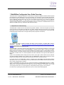
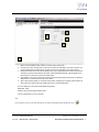
MOD-MBUS CONFIGURATOR SOFTWARE User Guide SyxthSense Ltd. 3 Topsham Units. Dart Business Park. Topsham. Exeter. Devon. EX3 0QH. United Kingdom. Tel: 0844 840 3100 www.syxthsense.com Fax: 0844 840 3200 Copyright Notice This document has been prepared by SyxthSense Limited using (i) its own proprietary information and (ii) proprietary information owned and controlled by other third parties (for which SyxthSense Limited has a right to use). The contents are copyrighted and must not be communicated in whole or in part to any other party without the prior written approval of SyxthSense Limited. The following notice applies to this document and shall be reproduced on any permitted copies: © 2013 SyxthSense Limited. All rights reserved. Any request for further information concerning this document should be addressed to: SyxthSense Limited 3 Topsham Units Dart Business Park Topsham Exeter EX3 0QH United Kingdom Online Store: www.syxthsense.com Enquiries: T: 0844 840 3100 F: 0844 840 3200 Copyright 2013 SyxthSense Ltd. Ver 0.1 MoD-M-BUS CONFIGURATION S/W USER GUIDE 2 CONTENTS 1 2 MOD/M-BUS CONFIGURATOR USER GUIDE OVERVIEW................................................................ 4 1. PREPARATION FOR COMMISSIONING ............................................................................................................ 4 2. EQUIPMENT OVERVIEW................................................................................................................................ 5 3. DEVICE SPECIFIC SETTINGS AND CHANGING THE MODBUS SETTINGS......................................................... 8 4. CHANGING THE MODBUS SETTINGS............................................................................................................. 8 5. SEARCHING FOR MBUS DEVICES ................................................................................................................ 8 6. ADDING NEW METERS ................................................................................................................................. 9 APPENDIX ...................................................................................................................................................... 12 PRE-COM CHECK SHEET ..................................................................................................................................... 12 MBUS Pre-Com check sheet............................................................................................................................. 12 Modbus Pre-Com check sheet .......................................................................................................................... 12 Modbus Connections ........................................................................................................................................ 12 3 DOCUMENT CONTROL ............................................................................................................................. 12 Online Store: www.syxthsense.com Enquiries: T: 0844 840 3100 F: 0844 840 3200 Copyright 2013 SyxthSense Ltd. Ver 0.1 MoD-M-BUS CONFIGURATION S/W USER GUIDE 3 1 Mod/M-Bus Configurator User Guide Overview The function of the Configurator software is to allow users to configure the Modbus to M-Bus modules supplied by SyxthSense Ltd. The software will scan a port connected on your computer for a level converter that must first be connected to allow communications. This software will search the com ports ticked as shown and search for a range of addresses and baud rates to find your units. The software will then allow you to connect to the Module and associated MBUS Meters. In a test mode you can view the meters and add them into the device for continuous polling of data and conversion into the Modbus protocol for connection to a Modbus Master such as a Webserver or BMS system (e.g. SyxthSense SDC Sedona Controller). 1. Preparation for commissioning The MOD-M-BUS modules will talk to the software using RS232 or RS485. To allow this to operate you will need a level converter as most laptops use USB ports only. When configured with the correct drivers your computer will allocate your level converter a Port number. A suitable level converter is the ADAM-4561 1-port Isolated USB to RS-232/422/485 Converter which can support either protocol (via specific connections). You can also use RS232 to RS485 converters with USB to Serial converters. A suitable USB to Serial is SyxthSense GLT-2368 (http://www.syxthsense.com/software-and-systems/glt-2368/glt-2368-usb-to-serialconverter/). The RS232 to 485 converter must support auto hand-shaking. Suitable converter is B&B Electronics 485SD9TB RS232/485 Port Powered converter. The MOD-M-BUS unit requires a 24Vdc power supply before it can be used with this software, it will also need cable to connect the level converter to the MOD-M-BUS converter and also cable to connect to your MBUS Meter. Ensure all connections are as per the documentation prior to applying power. For the avoidance of doubt, the MBUS network is not polarity sensitive however the cable used must be suitable for the total length of run and the quantity of meters on the run. Contact SyxthSense for further information on the types of cable allowed for MBUS. Further to this the Modbus network design must also use the correct type of cable and the end of line devices must be terminated as detailed in the guidance notes. The MOD-M-BUS device must be allocated a unique Modbus device address and the network baud rate must also be known to conclude the set-up. If you have more than one MOD-M-BUS device to configure on the same Modbus LAN then please configure each device in turn on a 1:1 basis locally, do not try to add the device to the Modbus LAN until each device has been correctly configured and re-checked. Important: The MOD-MBUS units will not allow you to configure the addressing of the MBUS Meters themselves. The MBUS meters or devices must be allocated individual addresses prior to trying to configure the MOD-MBUS devices. This will need additional time and specialist software and tools. Please verify and have confirmation of the addresses prior to trying communicating with the meters. For help and equipment to configure MBUS Addressing please contact SyxthSense. For further help on planning the project please see the pre-com check sheet included appendix. Online Store: www.syxthsense.com Enquiries: T: 0844 840 3100 F: 0844 840 3200 Copyright 2013 SyxthSense Ltd. Ver 0.1 MoD-M-BUS CONFIGURATION S/W USER GUIDE 4 2. Equipment Overview A typical strategy is as follows: DR60-24VDC Supply USB RS485 MOD-MBUS8/RS485 ADAM-4561 MBUS Meter Network 6 2 9 MBUS Meter Address (set by others) Online Store: www.syxthsense.com Enquiries: T: 0844 840 3100 F: 0844 840 3200 Copyright 2013 SyxthSense Ltd. Ver 0.1 MoD-M-BUS CONFIGURATION S/W USER GUIDE 5 3. 2 4. 5. 1. 1. 2. 3. 4. 5. When running the MBUS-CONF program the above window will be seen. Un-tick any com port not being used. Leave only the comm port allocated to your level convertor e.g. if unknown please check windows device manager to see the port allocated to your level convertor Deselect baud rates if unit baud rate is already known. E.g. if Default Speed of converter being used is 19200 then only leave 19200 ticked to save time scanning at different speeds. If the baud rate of your level converter is unknown then leave all speeds ticked. If the address of your level converter is known then please select the upper and minimum to reflect the address set. If not known then leave as shown above. When ready and the options you are aware of have been configured you can simply click this button to start a auto scan of the port and the software will find your connected device(s). If you are setting up a new unit then the defaults are typically: Baud Rate: 19200 Address: 255 (in above image set start to 255) Com port: Assigned by your own computer Note: If your unit type is known you may add it manually into your project by selecting the folder with the green cross. Online Store: www.syxthsense.com Enquiries: T: 0844 840 3100 F: 0844 840 3200 Copyright 2013 SyxthSense Ltd. Ver 0.1 MoD-M-BUS CONFIGURATION S/W USER GUIDE 6 When a new device has been found (or manually created) you will be presented with the following screen. This screen prepares the discovered module for searching the MBUS connection and finding any MBUS meters that are discoverable. 1. 2 1. 2. LOCAL COM PORT SETTINGS: The area deals with the settings of the connection being used to talk to the MOD-M-BUS module COMMON: Test Connection allows verification of the connection between the computer and the MODM-BUS unit. When a test is made the window will display the software version of the device and the state of the Module. See the following image that reflects a successful connection. (It is not necessary for an MBUS meter to be connected at this stage). Online Store: www.syxthsense.com Enquiries: T: 0844 840 3100 F: 0844 840 3200 Copyright 2013 SyxthSense Ltd. Ver 0.1 MoD-M-BUS CONFIGURATION S/W USER GUIDE 7 4 2. 3 Download Configuration allows any changes made in the Device Specific window to be sent to the MBUSModbus module. The Test button allows a connected MBUS meter and a configured MOD-MBUS unit to be visualised inside the Test Bench Area of the Window. This can be used once a meter has been connected to the MBUS-Modbus module and the software has searched and found the meter or a compatible template has been selected from the library. For live data to be seen, the correct M-Bus baud rate must be set. Usually this is 2400. Use a connected MOD-MBUS device to search the MBUS channel to find any configured meters 3. Device Specific Settings and changing the Modbus settings This area allows the specific configuration of the MOD-MBUS units selected. Here the device Modbus address, Baudrate of the Modbus Network, MBUS Baudrate and query timeout can be changed. These need to be set as suited by the site and networking requirements. When changes are made to any of these fields they will need to be sent to the MOD-MBUS device by using the DOWLOAD Configuration button in the Common area (section 2). 4. Changing the Modbus Settings Should the Modbus address and Modbus Baud rate be changed then you will need to create a new connection to the MOD-MBUS device you are configuring as the connection will be broken by the recent download. The easiest way to do this is to make the changes in Local Com Port Settings to match your new Modbus address and Baud Rate and then save your project using the Save Project Disc Icon on the tool bar (see above image 4). You will need to close the Project and re-open your saved project to restart with the new settings. From this point forward you will now be using your required Modbus Address and Baud rate to talk to your MBUS-Modbus unit. 5. Searching for MBUS Devices In the device specific area you can then select to search for MBUS Slaves. This will poll the MBUS network looking for MBUS Addresses within a range that you can specify with a live connection to the MOD-MBUS device. Online Store: www.syxthsense.com Enquiries: T: 0844 840 3100 F: 0844 840 3200 Copyright 2013 SyxthSense Ltd. Ver 0.1 MoD-M-BUS CONFIGURATION S/W USER GUIDE 8 6. Adding New Meters There are two ways to get your meters into the project file: 1. Allow the MBUS-Modbus unit to scan the network by selecting Search MBUS Slaves 2. Add the meters manually using the add device tool meters or create your own to suit your project. . Choose from a pre-defined Library of standard In this example I will select the Cyble Sensor and connect to a Cyble Sensor from Itron. I have created the meter into the project file. I have set the Modbus address to be 70, the Modbus Baud rate to be 19200 and the MBUS Baud Rate to be 2400. I had previously configured the MBUS address to be 5. By selecting the Cyble Meter in my project window I can set the Meter Address. (See next image) Online Store: www.syxthsense.com Enquiries: T: 0844 840 3100 F: 0844 840 3200 Copyright 2013 SyxthSense Ltd. Ver 0.1 MoD-M-BUS CONFIGURATION S/W USER GUIDE 9 Once the meter is in the project Window (See Below) the configuration must be sent to the MBUS-Modbus device 1. Simply select DOWNLOAD CONFIGURATION (1) from the Common settings window as above. The configuration will be sent to the device and from this point forward the meter can be polled by the unit. This can be tested and verified by selecting the Test button (2). The meter will be polled based on all the settings given and if successful the meter conditions will be seen as below Online Store: www.syxthsense.com Enquiries: T: 0844 840 3100 F: 0844 840 3200 Copyright 2013 SyxthSense Ltd. Ver 0.1 MoD-M-BUS CONFIGURATION S/W USER GUIDE 10 2 The Modbus register addressing can be seen in the test bench area, these can be configured into your Modbus master to permit Automated Reading of your MBUS meter. Continue to configure any additional meters, I recommend saving your project file after each meter is added to save changes as you progress. Online Store: www.syxthsense.com Enquiries: T: 0844 840 3100 F: 0844 840 3200 Copyright 2013 SyxthSense Ltd. Ver 0.1 MoD-M-BUS CONFIGURATION S/W USER GUIDE 11 2 APPENDIX 7. PRE-COM Check Sheet MBUS Pre-Com check sheet 1. 2. 3. 4. Have all the MBUS meters/devices been addressed, located and pre-configured Is the network fully connected Do I know the MBUS Baud rate? Is the cable type correct for this project Modbus Pre-Com check sheet 1. 2. 3. 4. 5. 6. 7. Do I know the Modbus address to be given to my level convertor(s)? Do I know the baud rate of the network to be given to the unit? Do I have a power supply for the MOD-MBUS? Do I have the software loaded and working? Do I have a level convertor to connect my laptop to the MOD-MBUS device? Do I know the port number that my level converter will use? Is the Modbus cable correctly connected to all Modbus devices observing polarity and termination of end of line devices. Modbus Connections Modbus can use different labelling on its devices depending on the manufacturer and options used, communications can be connected as +ve and –ve / A and B / Rx and Tx. Below is a table to help ensure connections are made correctly. A B -ve +ve Rx/TX - Rx/Tx+ The Devices at the end of the Modbus RS485 LAN must be terminated with a 120 Ohm resistor at each end. A three core cable should always be installed for Modbus wherever possible. 3 Document Control Version Date Change History 0.1 29-Jan-2013 Original Release Online Store: www.syxthsense.com Enquiries: T: 0844 840 3100 F: 0844 840 3200 Copyright 2013 SyxthSense Ltd. Ver 0.1 MoD-M-BUS CONFIGURATION S/W USER GUIDE 12 SyxthSense Limited 3 Topsham Units Dart Business Park Exeter EX3 0QH United Kingdom Enquiries: T: 0844 840 3100 F: 0844 480 3200 Online store: www.syxthsense.com Online Store: www.syxthsense.com Enquiries: T: 0844 840 3100 F: 0844 840 3200 Copyright 2013 SyxthSense Ltd. Ver 0.1 MoD-M-BUS CONFIGURATION S/W USER GUIDE 13