1
M1000 Series
Signal Conditioning
System User Guide
©1996 Micro Movements Ltd.
Contents
ii
M2200-8 Thermal Chart Recorder User Guide
©1993 Micro Movements Ltd.
M1000 Series Signal Conditioning System User Guide
SECTION 1 - INTRODUCTION
1
SECTION 2 - DESCRIPTION
2
2.1
General Description
2
2.1.1
2.1.2
2
4
Signal Conditioning Cabinets
Signal Conditioning
2.2
Applications
4
2.3
Specifications
5
2.4
Signal Conditioning Modules
6
2.5
Output Conditioning Modules
8
SECTION 3 - SET-UP
10
3.1
Installation
10
3.2
Preparing for use
11
3.2.1
3.2.2
3.2.3
11
11
11
3.3
3.4
Basic set up
Operating Controls
Switching on
Connection Details
12
3.3.1
3.3.2
3.3.3
3.3.4
3.3.5
12
12
12
13
17
Mains Input
Signal Input
Output Conditioning
Output Connections
A6 Inverter
Rack Mounting Kit (M1000-24 only)
SECTION 4 - OPERATION
©1996
Contents
17
18
4.1
Front Panel Controls
18
4.2
Rear Panel Controls
21
Micro Movements Ltd.
Contents
M1000 Series Signal Conditioning System User Guide
©1996
Micro Movements Ltd.
M1000 Series Signal Conditioning System User Guide
Introduction
SECTION 1 - INTRODUCTION
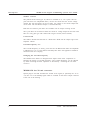
This manual has been produced to allow the User to make full use of the Micro
Movements M1000 Series Signal Conditioning System. It is not intended that the
User should undertake major maintenance, for which the System should be returned
to Micro Movements. Consequently some of the technical descriptions and
maintenance procedures are not explained in full.
For further details on Maintenance and Fault Finding please refer to the Service
Manual.
This manual is divided into 3 main sections, which cover:
Description
Set Up
Operation
WARNING
HEALTH AND SAFETY AT WORK
MICRO MOVEMENTS LIMITED HAVE ENSURED THAT, AS FAR AS
PRACTICABLE, ANY PERSON CARRYING OUT NORMAL MAINTENANCE
OPERATIONS ON THE ABOVE SYSTEM IS NOT EXPOSED TO ANY UNDUE
HAZARD FROM ELECTRIC SHOCK OR PERSONAL INJURY.
HOWEVER, MAINTENANCE AND/OR SERVICING OPERATIONS MAY
INVOLVE REMOVAL OF COVERS OR DISASSEMBLY OF COMPONENTS.
UNDER SUCH CONDITIONS THE INTEGRITY OF THE EQUIPMENT MAY BE
IMPAIRED. MICRO MOVEMENTS THEREFORE RECOMMEND THAT
MAINTENANCE IS ONLY CARRIED OUT BY A COMPETENT PERSON OR
PERSONS CONVERSANT WITH THE HAZARDS OF WORKING WITH
ELECTRO-MECHANICAL SYSTEMS.
©1996
Micro Movements Ltd.
1
Introduction
2
M1000 Series Signal Conditioning System User Guide
©1996
Micro Movements Ltd.
M1000 Series Signal Conditioning System User Guide
Description
SECTION 2 - DESCRIPTION
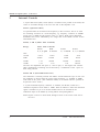
2.1
General Description
The M1000 series signal conditioning cabinets are multi-channel systems that can
accept signals from most types of transducers. These are conditioned, amplified
and matched to drive tape recorders, lightbeam recorders, computers, etc. The
following features are included in all systems:
2.1.1
•
Power supplies for all the transducers
•
Configuration switches, e.g. full, half or quarter bridge
•
Individual gain and balance controls
•
A digital monitor with channel selector
•
An accurate calibration facility.
Signal Conditioning Cabinets
Four cabinets types are available:
•
M1000-6
The M1000-6 is a self contained compact unit primarily intended for mobile
applications. It can house up to 6 channels of Micro Movements Signal
Conditioning Amplifiers.
•
M1000-12
The M1000-12 has similar facilities as the M1000-6 but with a maximum
channel capacity of 12. The M1000-12/P is similar but also has a postconditioning facility; i.e. filter, power amplifiers, etc. can be plugged into the
top of the cabinet.
•
M1000-16
The M1000-16 and -16/P have similar facilities to the M1000-12 and -12/P
respectively but with a maximum channel capacity of 16.
•
M1000-24
The M1000-24 and -24/P have similar facilities to the M1000-16 and -16/P
respectively but with a maximum channel capacity of 24.
©1996
Micro Movements Ltd.
1
M1000 Series Signal Conditioning System User Guide
Description
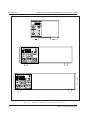
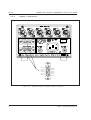
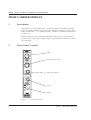
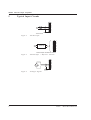
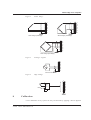
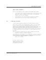
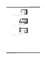
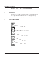
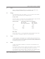
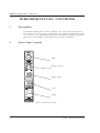
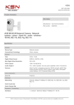
Figure 2-1
2
M1000-6 , M1000-12 and M1000-16 Front Panels
©1996
Micro Movements Ltd.
M1000 Series Signal Conditioning System User Guide
2.1.2
Description
Signal Conditioning
Standard plug-in modules are available to condition Pressure, Temperature,
Acceleration and Flow transducers, etc. Also available is a wide range of modules
that have been designed for special customer requirements (see section 2.4).
2.2
Applications
The cabinets have been designed to be used as stand alone units. In this mode they
are used to drive tape recorders, data loggers, computers or other data storage
equipment.
The cabinets also have facilities to drive Micro Movements M300H Lightbeam
Recorders and all the matching circuits for the galvanometers are included in the
modules. Direct interconnection cables are available from the M1000 to the M300H
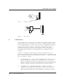
recorder.
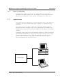
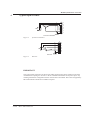
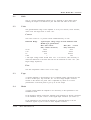
The M1000 series housings have been particularly designed to interface with DATA
ACQUISITION SYSTEMS. The voltage output connector on the rear of the housing
can be connected directly to a PC based data acquisition card, either ISA or
PCMCIA. Micro Movements can provide complete data acquisition systems or
advice on integration with an existing system.
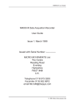
M1000 HOUSING
©1996
Micro Movements Ltd.
3
M1000 Series Signal Conditioning System User Guide
Description
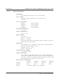
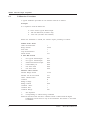
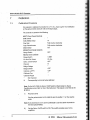
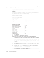
2.3
Specifications
Signal Input
7 pin lockable DIN connector, one for each channel
Power Supply
115/230V 45-440Hz, selectable via rear panel control
12/24VDC
Power Consumption
M1000-6
20VA maximum
M1000-12
25VA maximum
M1000-16
28VA maximum
M1000-24
30VA maximum
Operating Temperature
0°C to 40°C
Storage Temperature
-20°C to +70°C
Digital Monitor
3 1/2 digits
Range 1 - 1.999 volts
Range 2 - 19.99 volts
Dual range LED display shows channel number, calibration input and
voltage output for each channel.
Calibration
±1mV through ±10 V continuously variable (Four switched attenuator
ranges and Fine interpolation control).
Attenuator accuracy - 0.5%
Stability - 200 p.p.m./°C
Transducer Power Supply
3-12 VDC in 1V steps
Output Conditioning
-12/P, -16/P and -24/P model cabinets have an output conditioning
section below a hinged panel on the top cover. Each slot must be filled
with either a module or an M1088-P channel completion module to route
the voltage and current outputs to the rear panel.
Signal Outputs (VOLTAGE)
M1000-6
M1000-12
M1000-16
M1000-24
Standard
15 Pin D
15 Pin D
25 Pin D
25 Pin D
Optional
BNC
BNC
BNC
BNC
Special
As required subject to space limitations
4
©1996
Micro Movements Ltd.
M1000 Series Signal Conditioning System User Guide
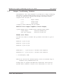
2.4
Description
Signal Conditioning Modules
The following signal conditioning modules are available for use with the M1000
Series.
M1020 Designers Module
A matrix-pattern printed circuit card contained within a standard amplifier module
which enables non-standard circuits, “specials”, etc. to be utilised within the system.
Input, output, power supplies, calibration, etc. are all accessed via the module
connector.
M1049 Oscillator/Amplifier/Demodulator/Filter
For energising and conditioning of variable reluctance transducers, differential
transformers, AC-excited LVDTs, etc. With built-in continuously variable, stored
calibration facility. Separately controlled buffered voltage output to drive data
storage equipment.
M1055 Passive Conditioner
Universal module with bridge balance, span adjust and shunt calibration controls,
for resistive transducers. Range adjustable by resistor-change to match most
inputs to low-frequency galvanometers.
M1060 High Gain DC Amplifier
Differential Amplifier for use with most types of low-level transducers, e.g. strain
gauges in 1, 2, or 4 active arm configuration, bonded and unbonded strain gauge
transducers and load cells. Separately controlled buffered output to drive data
storage equipment.
M1061 Thermocouple Amplifier
For use with thermocouples and similar low-level devices. Full scale output for 1mV
to 100mV input. Separately controlled buffered voltage output to drive tape
recorders, etc.
C1061/R Connector
Special connector with integral cold junction compensation for above.
M1070 Attenuator/Amplifier
General purpose unit for medium to high level inputs, e.g. potentiometric
transducers, DC/DC LVDTs, servo accelerometers, tape replay amplifiers.
Separately controlled buffered voltage output to drive data storage equipment.
©1996
Micro Movements Ltd.
5
Description
M1000 Series Signal Conditioning System User Guide
C1070/H Adaptor
High impedance adaptor, for operation of M1070 with piezo-electric sensors or
signals with very high source impedance.
M1071 Variable Attenuator
Resistive network to provide attenuation, matching and damping between high level
inputs and most types of galvanometer. Separately controlled buffered voltage
output to drive tape recorders, etc.
C103 High Voltage Connector
With 60dB balanced attenuator network for measuring high input voltages (up to
500V RMS).
C104 High Voltage Connector
With 80dB balanced attenuator network for measuring high input voltages (up to
500V RMS).
C/NA Shunt Connector
For current measurement (N specifies the current). Range 0.1 to 10 amps.
M1073 RMS/DC Converter
Precision rectifier unit for monitoring amplitude changes in AC waveforms. Includes
separate buffered voltage output for tape recording, etc.
M1080 Frequency/DC Converter
For use with impeller flowmeters, magnetic or photo-electric RPM pickups,
tachometers, vibration pickups. Separately controlled buffered voltage output to
drive data storage equipment.
M1085 Oscillator Module
Nine calibrated ranges from 20Hz to 10kHz (crystal controlled), for calibration of
M1080.
M1090 Series Filters
A range of filters is available from 2 to 6 pole with Butterworth, Bessel or Chebyshev
characteristic.
6
©1996
Micro Movements Ltd.
M1000 Series Signal Conditioning System User Guide
2.5
Description
Output Conditioning Modules
The M1000-12/P, -16/P, -24/P instruments are provided with an Output Conditioning
Stage which is accessible through the hatch at the top of the unit. If this section is
not used, the connections are normally linked through with M1088-P Channel
Completion Cards. The links are:
9 - 10
Output Common
7 - 12
Voltage Output
8 - 11
Current Output
A number of output conditioning units are available:
M1072-P Power Output Amplifier (Current Output)
A power amplifier option is available with the following possible outputs:
Current Output:
Galvo. Drive Amplifier:
±10mA into 500 ohms max.
±50mA into 42 ohms max.
M1090 Active Filters
Low Pass Active Filters are available. The type numbers of the filters are given as
follows:
M1090-02-* 2 pole Low pass
M1090-04-* 4 pole Low pass
M1090-06-* 6 pole Low pass
M1090-04/2-*/*
4 pole Low pass, 2 selectable cut-off frequencies
M1090-04/3-*/*/*
4 pole Low pass, 3 selectable cut-off frequencies
* = Cut-off frequency (-3dB)
Note: On the 04/2 and 04/3 selectable frequency versions, the maximum range of
frequencies on any individual PCB is 20:1
Normally filters are supplied with Butterworth characteristics unless otherwise
specified. Bessel, Chebychev or Paynter can be characterised at no extra cost.
©1996
Micro Movements Ltd.
7
M1000 Series Signal Conditioning System User Guide
Description
Number of Poles
The printed circuit board (type ‘P’) filters are available as 2, 4 or 6 poles. The two
pole units have two independent filters, one for the current and one for the voltage
outputs. The four pole filters can be on either the voltage or the current outputs but
not on both. The non-filtered output is connected directly.
Both the two and four pole filters are available with an output reversing switch.
The 6 pole filter can be fitted to either the current or voltage output but not both. This
filter is a unity gain type and is fitted with a bypass switch (‘Filter On/Off’).
Construction
The suffix P denotes that the filter is a PCB and is fitted into the output stage of the
amplifier cabinet.
Cut-Off Frequency “fc”
The Cut-Off Frequency is factory preset and for the Butterworth filter the amplitude
is 3dB down at “fc”. For the Bessel and Chebychev filters the application should be
discussed with the Company.
Changing the Cut-Off Frequency
The M1090 Series Filters are designed with “Equal Value” filter components to
facilitate the change of Cut-Off Frequency. The Cut-Off Frequency can be reduced
by either increasing the filter capacitors or alternatively increasing the two filter
resistors.
M1090/4-20 4to 20 mA converter
Special plug-in card that translates the normal 0-10v signal (or optionally the -10 to
+10) into a 4 to 20 milliamp signal which is available on the 'Galvo' output connector
at the rear of the housing.
8
©1996
Micro Movements Ltd.
M1000 Series Signal Conditioning System User Guide
Set-up
SECTION 3 - SET-UP
3.1
Installation
The M1000 Series Signal Conditioning System cabinets are portable and therefore
not dedicated to one installation point. During use there are some simple
precautions to follow if the system is to operate safely and correctly.
a)
Supply voltage
Before connecting the cabinet to the power supply, check that the voltage has
been set to the correct position for the local supply voltage and that the
appropriate fuse has been fitted. The supply voltage is selected by means of
a rotary switch located on the rear panel of the cabinet.
b)
The top cover should not be removed except by qualified personnel.
c)
It is essential that the air vents around the cabinet are not blocked while it is
in operation, as adequate ventilation is required to prevent overheating.
The following items are supplied with each cabinet:
©1996
•
1 Mains power lead with moulded socket.
•
1 x 7 pin locking DIN connector. One further connector is supplied with each
signal conditioning amplifier ordered with the mainframe.
•
1 set of manuals.
Micro Movements Ltd.
1
M1000 Series Signal Conditioning System User Guide
Set-up
3.2
Preparing for use
3.2.1
Basic set up
a)
Ensure the power switch is in the OFF position (located on the rear panel on
the M1000-6).
b)
Select the voltage of the power source using a screwdriver on the rear panel
selector. The settings are:
DC - 12V and 24V
AC - 115V and 230V, 45 - 400 Hz
3.2.2
c)
Connect the power source to the appropriate socket on the rear panel. In the
case of the M1000-12, -16 and -24 the left hand 4 pin socket is for the DC
supply, the right hand 3 pin socket for the AC supply. The M1000-6 has a
smaller 2 pin socket for the DC supply located above the 3 pin AC socket.
d)
Connect the 7 pin connectors to the signal input connectors (see section 3.3
for connection details).
e)
Connect the D-type output connectors to the voltage and current output
sockets (see section 3.3 for connection details).
Operating Controls
Set the operating controls on the front panel to suit the requirement ( see section 4
for the use of controls).
3.2.3
Switching on
Set the power switch to the ON position (located on the rear panel of the M1000-6).
The system should now be ready for use.
2
©1996
Micro Movements Ltd.
M1000 Series Signal Conditioning System User Guide
3.3
Set-up
Connection Details
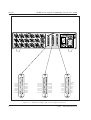
The rear panel connector layouts for the four cabinet types are shown in Figures 3-1
to 3-4.
3.3.1
Mains Input
This is a fixed socket with moulded free lead conforming to IEE regulations.
Europe:
Brown connects to Live
Blue connects to Neutral
Green/Yellow connects to Earth.
North America:
Black connects to Live
White connects to Neutral
Green connects to Earth.
Note: Set voltage selector to position for local supply with fuse value as follows:
220-260 VAC - 0.5 amp SLO BLO
100-130 VAC - 1 amp SLO BLO
3.3.2
Signal Input
The 7 pin connections for the input signals to the conditioning modules must be
correctly wired. Signal input pin connections are;
Pin
Connection
1
Transducer Supply +ve
2
Transducer Supply -ve
3
Not connected
4
Input LO
5
Input HI
6
Auxiliary Supply/Input
7
Frame
Note: The above connections only apply if there is a signal conditioner fitted to that
particular channel.
3.3.3
Output Conditioning
The M1000-12/P, -16/P and -24/P cabinets have an output conditioning section
(accessed by a hinged cover on top of the cabinet), which accepts various postconditioning cards, e.g. active filters, integrators, power amplifiers, etc. If this
section is not used, it is necessary to fit Channel Completion cards type M1088-P to
route the voltage and current outputs through to the rear panel D connectors.
©1996
Micro Movements Ltd.
3
M1000 Series Signal Conditioning System User Guide
Set-up
3.3.4
Output Connections
8
15
CH 6 LO
CH 5 LO
CH 4 LO
CH 6 HI
CH 5 HI
CH 4 HI
CH 3 LO
CH 2 LO
CH 1 LO
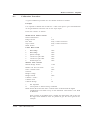
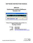
Figure 3-1
4
CH 3 HI
CH 2 HI
9
1 CH 1 HI
M1000-6 Voltage and Galvo Output Connectors
©1996
Micro Movements Ltd.
M1000 Series Signal Conditioning System User Guide
8
8
15
CH 6 LO
CH 5 LO
CH 4 LO
CH 2 LO
CH 1 LO
CH 5 HI
CH 4 HI
1 CH 1 HI
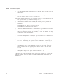
Figure 3-2
©1996
CH 8 LO
CH 7 LO
15
CH 12 HI
CH 11 HI
CH 10 HI
CH 9 LO
CH 3 HI
CH 2 HI
9
8
15
CH 12 LO
CH 11 LO
CH 10 LO
CH 6 HI
CH 3 LO
Set-up
CH 9 HI
CH 8 HI
9
1 CH 7 HI
CH 12
CH 10
CH 8
CH 9
CH 7
CH 6
CH 4
CH 2
Common
CH 11
CH 5
CH 3
9
1 CH 1
M1000-12 Voltage and Current Output Connectors
Micro Movements Ltd.
5
M1000 Series Signal Conditioning System User Guide
Set-up
13
13
25
CH 8 LO
CH 7 LO
CH 6 LO
CH 5 LO
CH 4 LO
CH 3 LO
CH 2 LO
CH 1 LO 9
CH 8 HI
CH 7 HI
CH 6 HI
CH 5 HI
CH 4 HI
CH 3 HI
CH 2 HI
1 CH 1 HI
Figure 3-3
6
13
25
CH 16 LO
CH 14 LO
CH 13 LO
CH 12 LO
CH 12
CH 10
CH 8
CH 9
CH 7
CH 6
CH 11 HI
CH 10 HI
9
CH 15
CH 13
CH 11
CH 14
CH 13 HI
CH 12 HI
CH 11 LO
Common
CH 16
CH 16 HI
CH 15 HI
CH 14 HI
CH 15 LO
CH 10 LO
CH 9 LO
25
CH 4
CH 2
1 CH 9 HI
CH 5
CH 3
9
1 CH 1
M1000-16 Voltage and Current Output Connectors
©1996
Micro Movements Ltd.
M1000 Series Signal Conditioning System User Guide
CH 1
1
CH 3
CH 5
CH 7
CH 9
CH 11
CH 13
CH 15
CH 17
CH 19
CH 21
CH 23
Common 13
9
CH 2
CH 4
CH 6
CH 8
CH 10
CH 12
CH 14
CH 16
CH 18
CH 20
CH 22
CH 1 HI 1
CH 2 HI
CH 3 HI
CH 4 LO
CH 5 LO
CH 6 LO
CH 6 HI
CH 7 HI
CH 8 HI
CH 7 LO
CH 8 LO
CH 9 LO
CH 10 LO
CH 9 HI
CH 10 HI
25 CH 24
CH 1 LO
CH 2 LO
CH 3 LO
CH 4 HI
CH 5 HI
Figure 3-4
©1996
9
CH 11 HI 1
9
CH 12 HI
CH 13 HI
CH 14 HI
CH 15 HI
CH 16 HI
CH 11 LO
CH 21 HI 1
CH 12 LO
CH 13 LO
CH 14 LO
CH 22 HI
CH 23 HI
CH 24 HI
9
CH 21 LO
CH 22 LO
CH 23 LO
CH 24 LO
CH 15 LO
CH 16 LO
CH 17 LO
CH 18 LO
CH 17 HI
CH 18 HI
CH 19 HI
CH 20 HI
CH 19 LO
CH 20 LO
25
13
Set-up
25
13
25
13
M1000-24 Voltage and Current Output Connectors
Micro Movements Ltd.
7
M1000 Series Signal Conditioning System User Guide
Set-up
3.3.5
A6 Inverter
The A6 Inverter is a factory installed option, which is available on all models,
allowing DC operation of the systems. The connections and precautions listed
below should be followed:
i)
Ensure that the mains lead is disconnected and set the Voltage Selector to
the correct position.
ii)
Connect the DC supply (Battery) to the cabinet using the cable supplied.
Cable Specifications
Nominal Area
6 sq. mm
10 sq. mm
16 sq. mm
35 sq. mm
Maximum Length
2M each lead
5M each lead
10M each lead
25M each lead
Supply Voltage Range
Nominal 12VDC:
Nominal 24VDC:
11 - 14V
22 - 29V
Nominal Current
12V
24V
3.4
M1000-6
1 amp
0.5 amp
M1000-12
1 amp
0.5 amp
M1000-16
2 amps
1 amp
M1000-24
2.5 amps
1.5 amps
Rack Mounting Kit (M1000-24 only)
The M1000-24 may be factory fitted with Rack Mounting Brackets, compatible with
standard 19" rack frames. If the rack depth is advised, telescopic slides can be
provided which fit directly onto the sides of the cabinet. The Rack Mounting option
may be retrofitted.
8
©1996
Micro Movements Ltd.
M1000 Series Signal Conditioning System User Guide
Operation
SECTION 4 - OPERATION
The M1000 Series of instruments are configured to accept a range of plug-in signal
conditioning modules and data amplifiers and can thus be used as completely selfcontained data acquisition systems with a very wide range of transducers, such as
load cells, thermocouples, strain gauges, pressure transducers, accelerometers,
flowmeters, displacement transducers etc..
The controls described in this section are adjusted in conjunction with the
conditioning module controls to set the system for use. Their operation in most
cases is self evident, however some details need explanation. For further details of
the conditioning controls, calibration and set up refer to the individual conditioning
module User Guides.
4.1
Front Panel Controls
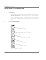
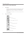
Figure 4-1 shows the front views of the M1000-6 and -12. The front panel controls of
the M1000-16 and -24 are similar to those of the M1000-12, only the number of
usable channels differ.
Figure 4-1
©1996
Front panel of M1000-6 , M1000-12 and M1000-16
Micro Movements Ltd.
1
M1000 Series Signal Conditioning System User Guide
Operation
Monitor
The monitor on the -12, -16 and -24 displays two lines of data, the -6 displays one
line:
•
Channel number being displayed or calibration e.g. CH11 or CAL. (Not for
M1000-6)
•
A 3 1/2 digit voltmeter with auto polarity which is used to monitor either the
voltage output from any signal conditioning module or the output from the calibrator.
There are also three switches associated with the monitor:
1.999/19.99
This is the Voltmeter Range Selector switch. The maximum value that can be
displayed is represented by the two switch positions, 1.999 and 19.99.
CH. No./CAL
The CH.No./CAL toggle switch (not M1000-6) is used to select the monitor input,
either a channel input or the calibration section output.
Galvo. OFF/ON
The Galvo. ON/OFF toggle switch (not M1000-6) controls the power supply to the
signal conditioning modules. With this switch on the Galvo. OFF position the
galvanometers can be rotated to a suitable mechanical zero, (refer to the
Calibration Section at the end of each module User Guide).
2
©1996
Micro Movements Ltd.
M1000 Series Signal Conditioning System User Guide
Operation
Channel No. (M1000-6)
This rotary switch selects the channel ouput (1 to 6) for display on the monitor. The
internal DC calibration voltage can also be selected for display.
Channel (M1000-12, -16, -24)
Two switches are used for channel selection:
a)
A rotary switch to select channels 1 to 12
b)
A toggle switch to select 1 to 12 or 13 to 24
In the 13 to 24 position 12 must be added to the value indicated on the rotary switch.
The channel selected is displayed on the monitor.
Bridge
The two switches in the BRIDGE box control the output of the Transducer Power
Supply.
The rotary switch selects the voltage of the power supply between 3 and 12 volts in
1V increments and the toggle switch is an ON/OFF control.
Calibrate
In the CALIBRATE box there are two switches and a potentiometer to control the
M1016 calibrator. The range switch is a four position rotary switch with the ranges
10mV, 100mV, 1V and 10 volts. The three position toggle switch gives three values
of calibration:
Positive, OFF and Negative.
The fine gain potentiometer allows adjustment of the calibration voltage to any
value. The calibration can be set utilising the monitor in the CAL position. To set a
small voltage accurately adjust the value on a higher range of the rotary switch and
then turn to the lower range.
e.g.
©1996
If a value of 4.32 volts is set on the 10V range and the rotary switch is turned
to the 10mV range, a voltage of 4.32mV will appear at the input to the
amplifiers. More details can be obtained from the calibration section
contained within the indiviual module User Guides.
Micro Movements Ltd.
3
M1000 Series Signal Conditioning System User Guide
Operation
4.2
4
Rear Panel Controls
•
Input Connectors - 7 pin DIN. (See section 2 for connection details).
•
Voltage Outputs - Female D connector contains voltage output suitable for tape or
logger from each of the signal conditioning channels.
•
Galvanometer Outputs - Female D connector contains output for connections to a
Micro Movements galvanometer from each of the signal conditioning channels.
•
Voltage Selector - Rotary switch for selection of required supply voltage, 12VDC,
24VDC, 115VAC or 230VAC.
•
DC Fuse - 2 amp (M100-6) 5 amp (M1000-12, -16, -24), 5 x 20mm fuselink.
•
DC Power In - 2 pin connector (M1000-6), 4 pin XLR connector (M1000-12, -16, 24).
•
AC Power In - standard IEC socket.
•
Power - On/Off switch for instrument (M1000-6 only), applicable to DC or AC
supply.
•
AC Fuse - 0.5 amp, 5 x 20mm fuselink.
©1996
Micro Movements Ltd.
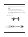
C103/C104 High Voltage Connectors
C103/C104 HIGH VOLTAGE CONNECTORS
CONTENTS
1
©1996
Description
2
1.1
1.2
2
2
Attenuation
Installation
2
Calibration
2
3
Typical Input Circuit
3
Micro Movements Ltd.
1
C103/C104 High Voltage Connectors
C103/C104 HIGH VOLTAGE CONNECTORS
1
Description
The C103 and C104 are High Voltage input connectors for use with signal
conditioning amplifier modules. The C103 connector includes a 60dB balanced
attenuator with an input impedance of 10 Megohms to earth on each input (20
megohms balanced). The C104 connector includes an 80dB balanced attenuator
with an input impedance of 100 Megohms to earth on each input (200 megohms
balanced). Both include a mating socket for connection to the high voltage source.
They can be used with the Mxx60 and Mxx70 amplifiers to extend their range to read
voltages up to 250 volts A.C. and also with the Mxx80 to measure the frequency of
high A.C. voltages, e.g. 230V/115V power lines.
1.1
Attenuation
C103 Fixed 60dB (1,000:1)
C104 Fixed 80dB (10,000:1)
1.2
Installation
Incoming High Voltage lead:
1
Lo
2
Hi
3
Earth
} Signal Input
WARNING
THIS CONNECTOR MUST BE EARTHED TO PIN 3 OF INPUT CONNECTOR
AND CONNECTOR SHELL.
2
©1996
Micro Movements Ltd.
C103/C104 High Voltage Connectors
2
Calibration
When used with Mxx60 and Mxx70 modules, the calibration procedures are followed
as per the individual modules and the voltage referred to the input is multiplied by
either 1,000 (C103) or 10,000 (C104).
Example
An input voltage of 200V is required to deflect 2 cm on the recorder.
The Mxx60 or Mxx70 are calibrated using a calibration voltage of 200 divided by
10,000 = 20 mV.
The Mxx80 calibration is not affected by the use of the C104. It should be noted
however, that the Mxx80 has a minimum sensitivity of 10 millivolts RMS. When the
Mxx80 is used with the C104 the minimum sensitivity of the Mxx80 is therefore
increased to 100V RMS.
3
Typical Input Circuit
2
Earth
Figure 1
3
1
2
3
4
5
6
7
High Voltage
Figure 2
©1996
C104
1
Micro Movements Ltd.
C103/C104 Side View
3
C103/C104 High Voltage Connectors
4
©1996
Micro Movements Ltd.
C1061 Series Thermocouple Reference Junction Connector
2
©1996
Micro Movements Ltd.
CN/A Current Shunt Connectors
C103/C104 HIGH VOLTAGE CONNECTORS
1
Description
The CN/A series are current shunt connectors for use with signal conditioning
amplifier modules. The CN/A contains a very low resistance, non-inductively
wound copper wire with voltage take-off points fed to the 7-pin DIN connector. The
value of the shunt resistance provides for an insertion voltage drop of 50mV at
maxiomum rated current. There are three model allowing for maximum currents of
10Amp, 5Amp and 1Amp. They can be used with the Mxx60 and Mxx70 amplifiers
and are suitable for AC and DC current measurements.
1.1
1.2
Shunt Values
C10/A
10 amps (50mV drop at 10 amps)
C5/A
5 amps (50mV drop at 5 amps)
C1/A
1 amp (50mV drop at 1 amp)
Installation
Incoming lead:
1
Not connected
2
Earth
3
Input High
4
Input Low
WARNING
THIS CONNECTOR MUST BE EARTHED TO PIN 2 OF INPUT CONNECTOR
AND CONNECTOR SHELL.
2
©1996
Micro Movements Ltd.
CN/A Current Shunt Connectors
4
©1996
Micro Movements Ltd.
M1043 Synchro/D.C. Converter
M1043 SYNCHRO/D.C. CONVERTER
CONTENTS
©1996
1
Description
2
2
Front Panel Controls
2
2.1
2.2
2.3
2.4
3
3
3
3
Shift
Tape
Sector
Gain
3
Specification
4
4
Typical Input Circuits
4
5
Calibration
5
5.1
5
Micro Movements Ltd.
Calibration Procedure
1
M1043 Synchro/D.C. Converter
M1043 SYNCHRO/D.C. CONVERTER
1
Description
The M1043 Synchro/DC Converter produces a DC output signal proportional to the
angular position of a synchro or resolver. The input range is from 11.8 to 90VAC.
Applications include radar antenna position information, C.N.C. machine tool positional
control, motor control, robot axis control, gyros and general aircraft and marine use. The
module comprises a high precision integrated converter and DAC. The gain and sector
controls allow maximisation of angular resolution.
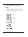
2
Front Panel Controls
Shift
Tape
Sector
Gain (Coarse)
Gain (Fine)
Figure 1
2
M1043 Front Panel
©1996
Micro Movements Ltd.
M1043 Synchro/D.C. Converter
2.1
Shift
This is a 22-turn potentiometer which acts as a back-off or output offset control on the
current output, enabling the galvanometer to be shifted over plus or minus full scale output.
2.2
Tape
A 15-turn potentiometer is used to adjust the voltage output of the amplifier independent of
the galvanometer output. The tape voltage output can be used to drive recorders,
oscilloscopes, digital voltmeters or other voltage driven devices. The output voltage is
adjustable up to 2V DC.
2.3
Sector
An 8 position rotary switch is used to select one of eight sectors, 0 - 360° in 45° steps. The
sector control injects a fixed offset and places the zero at the beginning of the selected
sector (as shown in the diagram at the bottom of the front panel). The shift control provides
fine trimming of the zero position.
Using these controls allows, at one extreme, one complete revolution (360°) to be set for
full scale output, or, at the other extreme, 315° to 360° to be set for full scale output.
2.4
Gain
The range over which the unit will operate is determined by two controls, coarse and fine.
Coarse
The coarse control is a rotary switch giving the following gain values:
x1
x2
x4
x8
Fine
The fine control is a 15-turn potentiometer which interpolates the switched steps.
©1996
Micro Movements Ltd.
3
M1043 Synchro/D.C. Converter
3
Specification
Input Configuration:
Input Impedance:
Input Range:
Input Frequency:
Resolution:
Accuracy:
Repeatability:
Bandwidth:
Tracking Rate:
Settling Time:
Noise:
Sector:
Gain:
Shift:
Output Voltage:
Output Impedance (Voltage):
Output Current:
Output Impedance (Current):
Package:
4
S1, S2, S3, R1, R2 Synchro
S1, S2, S3, S4, R1, R2 Resolver
160 Kohms differential
11.8V line to line (S1 - S4)
4V to 50V r.m.s. (R1 - R2)
50Hz to 400Hz
12 bit (5.3 minutes)
±10 minutes
5.3 minutes
500 Hz
200 RPS
15 mS
Less than 0.1% (r.t.o.)
8 ranges, 0 - 360° in 45° sectors
4 ranges, x1, x2, x4, x8 with interpolate
control.
0 - 45°
Up to ±10V DC
0.5 ohms
±10mA into 120 ohms
250 ohms
Double width M1000 series module.
©1996
Micro Movements Ltd.
M1043 Synchro/D.C. Converter
4
Typical Input Circuits
1
2
3
4
5
6
7
REF.
Synchro Transmitter
Figure 2
Synchro Transmitter
1
2
3
4
5
6
7
REF.
Figure 3
Resolver
Resolver
IMPORTANT
The typical inputs shown are for direct input. Many applications require isolation in the form
of transformer coupling for resolvers or Scott connected transformers for Synchro input. Any
isolating transformer configuration will be external to the instrument. These can be supplied by
Micro Movements. Details are available on request.
©1996
Micro Movements Ltd.
5
M1043 Synchro/D.C. Converter
6
©1996
Micro Movements Ltd.
M1049 Carrier Oscillator, Amplifier and Demodulator
M1049 CARRIER MODULE
1
Description
The M1049 is a self-contained carrier oscillator, amplifier, demodulator and filter
which is primarily intended for operation with inductive transducers in half or full
bridge configuration, e.g. variable reluctance transducers, differential transformers
(LVDTs) etc.
Features include low noise and high bandwidth for this type of system, full input
protection up to ±30V, wide dynamic range and galvanometer protection by output
current limiting.
2
Front Panel Controls
Shift
Span (Coarse Gain)
Span (Fine Gain)
Tape
Mode
Figure 1
2
M1049 Front Panel
©1996
Micro Movements Ltd.
M1049 Carrier Oscillator, Amplifier and Demodulator
3
Internal controls
3.1
Calibration Level
There are three calibration voltages which can be set by the DIP switches on the
side of the module.
Switch 3
Range
Pole 1 Pole 2 Pole 3 Calibration
Typical Applications
LOW
ON
OFF
OFF
5mV RMS
Resistance Bridge
MEDIUM
OFF
ON
OFF
20mV RMS
Inductive Pressure
HIGH
OFF
OFF
ON
100mV RMS
LVDTs
The amplifier has a separate buffered voltage output which appears on a socket at
the rear of the recorder/signal conditioning cabinet. The nominal output level with a
10cm deflection on the galvanometer can be adjusted by means of the
potentiometer marked Tape between 1V and 2V approximately.
3.2
Zero Balance Range
There are three Zero Balance ranges which can be preset by the DIP switches on
the side of the module.
Switch 3
Range
Pole 4
Fine
ON
Medium OFF
Coarse OFF
4
Pole 5
OFF
ON
OFF
Typical Applications
Bridges with a close balance (within ±0.2%)
Inductive Pressure Transducers with balance ±2%
LVDTs with balance ±10%
Bridge Completion
The M1049 will operate directly with transducers in the half or full bridge mode (see
section 6).
4
©1996
Micro Movements Ltd.
M1049 Carrier Oscillator, Amplifier and Demodulator
6
Typical Input Circuits
1
2
3
4
5
6
7
Variable Reluctance
Figure 2
Variable Reluctance
1
2
3
4
5
6
7
Figure 3
Differential Transformer
1
2
3
4
5
6
7
Figure 4
6
Piezoresistive Transducer
Piezoresistive Transducer
©1996
Micro Movements Ltd.
M1049 Carrier Oscillator, Amplifier and Demodulator
Note:
7.1
•
On the M12-150A the Galvo. ON/OFF switch is fitted inside the Signal
Conditioning access hatch on the top of the instrument.
•
This feature is not fitted to M1000-6.
Calibration Procedure
1)
Recorders Only
Use the galvanometer tool to rotate the galvanometer to align the spot to
position 11 on the viewing scale.
Note: If all channels are not in use it is preferable to use the centre channels for the
best optical fidelity, e.g. Channels 3 through to 7.
2)
Galvo. ON/OFF switch to ON.
This switch provides power to the amplifiers. Rotate the shift control to set
the monitor voltage to 0.00V. Observe the galvo. spot on the viewing scale; it
should be on the position as set in 1). i.e. 11. If it is not, check the procedures
again. Otherwise there is a fault in the amplifier.
3)
RUN/OFF/CAL switch to CAL.
Use the fine gain potentiometer to set the spot to give a deflection of 5.56cm
on the viewing scale, i.e. 11 - 5.56 = 5.44.
4)
Use the TAPE potentiometer to set the Monitor display to 1.112 volts
5)
RUN/OFF/CAL switch to RUN.
Position the LVDT armature to a known position, e.g. centre point. Use the
zero balance to adjust the monitor to the corresponding value, e.g. the centre
point would be 1.00 volts.
The system is now fully calibrated and ready for use.
8
©1996
Micro Movements Ltd.
M1060 High Gain Amplifier
M1060 HIGH GAIN AMPLIFIER
CONTENTS
1
Description
2
2
Front Panel Controls
2
2.1
2.2
2.3
2.4
3
3
3
4
3
4
©1996
Zero
Span
Tape
Mode
Internal controls
4
3.1
3.2
4
4
Bridge Completion
Low Noise Operation
Sensor Excitation
5
4.1
4.2
5
5
Transducer Supply
Zero Balance Range
5
Voltage Output Range
5
6
Specification
6
7
Typical Input Circuits
6
8
Calibration
7
8.1
8
Micro Movements Ltd.
Calibration Procedure
1
M1060 High Gain Amplifier
M1060 HIGH GAIN AMPLIFIER
1
Description
M1060 is a high gain differential-input DC amplifier primarily intended for operation
with strain gauges in 1, 2 or 4 external arm mode, load cells, pressure transducers
and similar low-level sensors.
Features include high input impedance, low noise and drift, full input protection up to
30V differential, wide dynamic range and galvanometer protection by output currentlimiting.
2
Front Panel Controls
Zero
Span (Coarse Gain)
Span (Fine Gain)
Tape
Mode
Figure 1
2
M1060 Front Panel
©1996
Micro Movements Ltd.
M1060 High Gain Amplifier
2.1
Zero
This is a 22-turn potentiometer which functions as a bridge balance or input offset
control. Its range is approximately ±20mV at the input terminals (±4000 microstrain
at 10V bridge excitation). However, the range can be modified by internal
adjustment, (see section 4.2).
2.2
Span
The amplifier span (gain) is set by two controls, coarse and fine, which cover the
approximate range 20 to 5000:1.
Coarse Gain
The Coarse Gain control is a 10-position rotary switch calibrated such that in each
successive position the gain is halved. The gain settings are as follows:
Position Gain (approx.)
0
1
2
3
4
5
6
7
8
00
5000
2500
1250
625
312
156
78
39
20
0.5
Typical input for a 5cm deflection
Min. (V)
Max. (V).
0.4
0.7
0.7
1.5
1.5
3
3
6
6
11
11
22
22
45
45
90
90
175
N/A
N/A
Fine Gain
The Fine Gain control is a 15-turn potentiometer which interpolates the gain steps
so that the gain is continuously variable over the switched range.
2.3
Tape
A separate amplifier is incorporated to give a buffered voltage output from the unit to
drive oscilloscopes, tape recorders, etc. via the Voltage Output connector located
on the cabinet rear panel. This is adjustable by means of a 15-turn potentiometer on
the module front panel up to ±2V DC.
©1996
Micro Movements Ltd.
3
M1060 High Gain Amplifier
2.4
Mode
A toggle switch enables the amplifier to be used easily in the Operational or the
Calibration mode.
In the Operation (RUN) position the amplifier input terminals are directly connected
to the transducer via pins 4 and 5 on the Signal Input Connector (see section 8).
In the Calibration (CAL) position the input is connected to a DC calibration voltage
derived from the recorder or signal conditioning cabinet being used.
3
Internal controls
3.1
Bridge Completion
The amplifier may be used with resistive bridge networks in the 1, 2 or 4 arm mode.
In the 1 or 2 arm mode bridge completion is achieved by connecting dummy bridge
arms within the amplifier by means of an internal switch (SW2).
The switch is a 6-pole 2-position type, of which poles 1, 2 and 3 are concerned with
bridge conditioning. The dummy bridge arms should be switched in according to the
input configuration, as follows:
Full Bridge:
In this case the bridge is completed within the transducer,
therefore poles 1, 2 and 3 should be in the Open position.
Half Bridge:
Poles 1 and 2 are Closed, bringing in the two 499 ohm dummy
arms (R25 and R26). Pole 3 remains Open.
Quarter Bridge: Poles 1, 2 and 3 are Closed. Note that closing Pole 3 brings in
R27, which is normally 120 ohms. If the resistance of the single external bridge arm
is different from this value R27 must be changed to match it. (See also Typical Input
Circuits).
3.2
Low Noise Operation
To minimise output noise at high gains a low pass filter can be switched in by
closing Poles 4 and 5 of SW2. This, however, has the effect of reducing the
bandwidth to approximately 150Hz.
4
©1996
Micro Movements Ltd.
M1060 High Gain Amplifier
4
Sensor Excitation
4.1
Transducer Supply
The 3 - 12V DC transducer supply (M1015) appears on pins 1 and 2 of the amplifier.
These are connected (via R1 and R2) to pins 3 and 4, which in turn are connected to
pins 1 and 2 on the 7-pin Signal Input Connector at the rear of the instrument. Thus
the transducer cannot be energised unless there is an amplifier present in that
particular channel. Note that the amplifier is normally supplied with R1 and R2
replaced by wire links so that the full supply (3 - 12V DC as selected by the Bridge
Volts switch) appears across the transducer. However, if a reduced supply is
required on a particular channel these may be replaced by resistors of the
appropriate value to act as droppers in the supply lines.
For example:
With 10V excitation selected, a particular strain gauge is
required to be energised with 2.5V.
Bridge resistance = 120 ohms
Bridge excitation = 2.5V
Volt drop required = 7.5V
Therefore:
R1 + R2 = (120x7.5)/2.5 = 360 ohms
So R1 and R2 are 180 ohms each.
Provision is also made to reverse the excitation polarity by means of links, (A or B),
on the board, or of course this may also be achieved by reversing pins 1 and 2 on
the Signal Input connector.
4.2
Zero Balance Range
Bridge balance is set by a 22-turn potentiometer which has a nominal range of
±20mV at the input (±4000 microstrain for 10V bridge excitation). For transducers
with a very large residual imbalance the range of this control may be increased by
the adjustment of R10.
5
Voltage Output Range
The amplifier has a separate buffered voltage output which appears on the Voltage
Output socket on the rear of the instrument. The nominal output level with a 10cm
deflection on the galvanometer can be adjusted by means of the potentiometer
marked Tape up to ±2V DC.
©1996
Micro Movements Ltd.
5
M1060 High Gain Amplifier
6
Specification
Input Configuration:
Input Impedance:
Input Mode:
High Gain Differential
1 Megohm Differential
1) Resistive bridge in 1, 2 or 4 arm connection with
internal bridge completion.
2) Low level signals generally.
Up to 500 mV (approx.)
30V D.C.
90dB (D.C. to 60 Hz)
Less than 5 microvolts r.m.s.(r.t.i.) at max. gain.
Less than 2 microvolts/°C (r.t.i.) at max. gain.
D.C. - 5KHz.
20 - 5,000 in switched steps with interpolate
control.
Up to ±10V DC
0.5 ohms
±10mA into 120 ohms
250 ohms
Standard M1000 series module
Input Range:
Maximum Input:
Common Mode Rejection:
Noise:
Drift:
Bandwidth:
Gain:
Output (Voltage):
Output impedance (Voltage):
Output (Current)
Output Impedance (Current):
Package:
7
Typical Input Circuits
1
2
3
4
5
6
7
1
2
3
4
5
6
7
Strain Gauge (1/4 Bridge)
Strain Gauge (1/2 Bridge)
1
2
3
4
5
6
7
Strain Gauge (Full Bridge)
Figure 2
6
Strain Gauge
©1996
Micro Movements Ltd.
M1060 High Gain Amplifier
1
2
3
4
5
6
7
Analogue Signals
Figure 3
Analogue Signals
2
Earth
Figure 4
8
3
C104
1
1
2
3
4
5
6
7
High Voltage
Calibration
A true calibration of any system can only be achieved by applying a known physical
stimulus to the sensor, for example, if the sensor is a pressure transducer, by the
use of a deadweight tester, or, in the case of a load cell, by applying known weights,
etc. The M1016 calibrator works by removing the output connections from the
transducer and injecting a known DC voltage into the amplifier input which
corresponds to the signal produced by the transducer for a given stimulus, this
being determined by reference to the manufacturers test certificate for that
transducer.
Confusion is sometimes caused during the calibration procedure due to the
apparent zero shift produced by the different operating modes. It is important for the
user to understand why this may occur and how to correct for it. There are basically
three zero modes to consider:
©1996
a)
The galvanometer zero - That is, the true mechanical zero when no current is
flowing through the coil. The best way to determine this is to switch the
supply to the amplifier off and then the galvanometer may be rotated so that
the spot is focused at the point on the chart where the zero for that particular
channel is required. The Galvo. On/Off switch is used for this purpose.
b)
The amplifier zero - The M1060 module has a variable zero, which is
controlled by the potentiometer marked Zero. In practice the amplifier zero
should be made coincident with the galvanometer zero by the use of this
control. Switch the mode switch on the amplifier to Cal and the Ch. No./Cal
Micro Movements Ltd.
7
M1060 High Gain Amplifier
switch on the recorder to Ch. No. The meter should now read 0.00V. Adjust
using the Zero potentiometer.
c)
The sensor zero - Virtually all sensors, except some self-generating types,
have a residual zero offset, that is an output which is present when no
physical stimulus is applied by the system under test. This may be due to the
sensor itself, e.g. mis-match between strain gauges in a Wheatstone bridge,
or to physical effects. e.g. an accelerometer would have an output equivalent
to 1g in the vertical plane, an absolute pressure transducer would have an
output equivalent to ambient barometric pressure, etc. or a combination of
both these conditions. This offset can be nulled by the amplifier zero control,
as in b) above.
There are two further considerations regarding the zero condition:
d)
If a sensor is calibrated in the laboratory and then taken out and mounted on
the system under test there may be a difference in the zero due to a change
in the temperature or mounting stresses, etc., and this should simply be
nulled off as in b) above, the calibration is normally unaffected.
e)
When the amplifier is switched from Run to Cal mode there may be a zero
shift due to a change in the input conditions. This can be nulled as before
without any effect on the calibration.
Mode Switch (Amplifier)
This is usually a 2-pole changeover switch connected to the amplifier input
terminals.
8.1
•
In the Operation (RUN) position the amplifier input is connected directly to
the signal source (usually a transducer) via pins 4 and 5 on the Signal Input
connector at the rear of the instrument.
•
In the Calibration (CAL) position the input is connected to a calibration
voltage derived from the recorder or signal conditioning cabinet.
•
There are some versions of the M1060 module which are fitted with other
types of calibration facility (e.g. Shunt cal.). If in doubt consult the Company.
Calibration Procedure
A typical calibration procedure for one channel would be as follows:
Take a pressure transducer with a nominal output of 40mV for full scale pressure
with 10V excitation (typical for an unbonded strain gauge type). However, it is
unlikely that any particular transducer would have an output of exactly 40mV, more
likely it would be somewhere within ±10% of this value. So, we look at the
manufacturers calibration certificate supplied with the transducer and see that this
is a 75 PSI unit which has an output of +38.68mV at 75 PSI if energised with a 10V
DC supply.
8
©1996
Micro Movements Ltd.
M1060 High Gain Amplifier
Note: If energised by a different supply the output is normally pro-rata but the
temperature coefficient is sometimes degraded.
The transducer has a zero imbalance (i.e. an output when no pressure is applied) of
-2.97mV. Therefore the total output change for 75 PSI applied is the sum of these
two (because the zero imbalance happens to be negative):
38.68 + 2.97 = 41.65mV.
It would be sensible if we made 75 PSI equivalent to 7.5cm excursion on the chart so
that in analysis the pressure is read direct from the grid lines (1cm = 10PSI). Thus
the calibration figure would be:
41.65 x (10/7.5) = 55.5mV for 10cm deflection.
Preset the controls as follows:
M1060 Front Panel Controls
Zero Balance Potentiometer
*
Range Switch :
6
Fine Gain
Fully Counter-clockwise
Tape Control
Fully Counter-clockwise
Run/Cal Switch
Cal
DIP Switch
1
Half Bridge
OFF
2
Half Bridge
OFF
3
Quarter Bridge
OFF
4
Low Pass Filter
OFF
5
Low Pass Filter
OFF
6
Not Used
OFF
Monitor Unit Controls
Monitor Range Switch
19.99
Monitor Ch. No./Cal Switch
Cal
Galvo. On/Off
OFF
Channel
N
Bridge Voltage
(as required for transducer)
10V
Bridge On/Off
OFF
Calibrate +/OFF/+
Calibrate Fine
*
Calibrate Range
10V
*
Not Important
N
Corresponding to channel being calibrated
Note: On the M12-150A the Galvo. On/Off switch is fitted inside the Signal
Conditioning access hatch on top of the instrument. This feature is not fitted
to M1000-6.
©1996
Micro Movements Ltd.
9
M1060 High Gain Amplifier
1)
Using the Calibrate FINE potentiometer set the voltage on the Monitor to
5.55V.
2)
Turn Calibrate RANGE to 100mV. There will now be 55.5mV on the
mainframe calibration bus.
3)
Recorders only. Use the galvanometer tool to rotate the galvanometer to align
the spot to position 11 on the viewing scale.
Note: If all channels are not in use, it is preferable to use the centre channels for the
best optical fidelity.
4)
Galvo. ON/OFF switch to ON. (This switch provides power to the amplifiers.)
Calibrate +/OFF/- switch to OFF
Monitor CH. No./CAL switch to CH. No.
5)
Adjust the ZERO balance potentiometer on the amplifier to give 0.00V on the
monitor. Observe the galvo. spot, it should correspond to the position set in 3)
i.e. 11. If there is a discrepancy, recheck, as either the amplifier is faulty or
there has been a wrong setting.
6)
Calibrate +/OFF/- switch to +.
Adjust the spot deflection to 10cm. i.e. position 1 on the viewing scale using
the FINE gain control on the amplifier. If 10cm cannot be achieved turn the
RANGE switch one position clockwise to increase the gain by 2, then reduce
the FINE gain to re-adjust to 10cm.
7)
Using the TAPE potentiometer on the amplifier, set the monitor voltage to a
suitable value, e.g. 2.00V. At this stage the system has been calibrated for a
sensitivity of 1cm/10 PSI on the recorder and a voltage output of 200mV per
10 PSI.
8)
Calibrate +/OFF/- switch to OFF.
If there has been a change from the original settings of 11 on the graticule or
0.00V on the monitor repeat the above procedure from the original preset
values in order to fine tune the system.
9)
RUN/CAL switch on the amplifier to RUN.
Use the ZERO balance potentiometer to set 0.000V on the monitor. The
galvanometer spot should still correspond to position 11 on the viewing scale.
10)
Bridge ON/OFF switch to ON
The zero will almost certainly move due to residual offset. Use the Zero
control to position the spot to the original zero position, i.e. 11 on the
graticule.
11)
10
The system is now fully calibrated and ready for use. If a different position is
©1996
Micro Movements Ltd.
M1060 High Gain Amplifier
preferred for the galvo. mechanical zero, set the Galvo. ON/OFF switch to the
OFF position before moving the galvo. Return the switch to ON after the
galvo. has been set.
12)
©1996
If, after step 10), the galvo. or voltmeter are completely off scale note the
position of the range switch and temporarily reduce the gain of the amplifier
by turning the range switch counter-clockwise one or two positions to find the
spot and then re-balance. If it still cannot be re-balanced there must be a fault
in the bridge circuit, all four arms of the bridge should be checked at the free
connector.
Micro Movements Ltd.
11
M1060 High Gain Amplifier
12
©1996
Micro Movements Ltd.
M1061 Thermocouple Amplifier
M1061 THERMOCOUPLE AMPLIFIER
CONTENTS
1
Description
2
2
Front Panel Controls
2
2.1
2.2
2.3
2.4
3
3
3
3
3
©1996
Offset
mV f.s.d.
Tape
Mode
Internal controls
4
3.1
4
Compensation Range
4
Specification
5
5
Typical Input Circuits
6
6
Calibration
7
6.1
8
Micro Movements Ltd.
Calibration Procedure
1
M1061 Thermocouple Amplifier
M1061 THERMOCOUPLE AMPLIFIER
1
Description
M1061 is a high gain amplifier for use with thermocouples and similar low-level
sources. (A special input connector, type C1061/R, with a built-in cold junction
reference, is available for use with this module.)
Features include high input impedance, low noise and drift and input protection up to
±12V across the input terminals.
2
Front Panel Controls
Offset
mV f.s.d.(Coarse Gain)
mV f.s.d.(Fine Gain)
Tape
Mode
Figure 1
2
M1061 Front Panel
©1996
Micro Movements Ltd.
M1061 Thermocouple Amplifier
2.1
Offset
A 22-turn potentiometer which acts as a back-off or input offset control enabling the
output to be shifted over plus and minus full scale range.
2.2
mV f.s.d.
The amplifier gain is set by two controls, coarse and fine.
Coarse Gain
The Coarse Gain control is a rotary switch calibrated in input millivolts for full-scale
output in the following steps:
100mV
30mV
10mV
3mV
1mV
Fine Gain
The Fine Gain control is a 15-turn potentiometer which interpolates the gain steps
so that the gain is continuously variable over the switched range.
2.3
Tape
A separate amplifier is incorporated to give a buffered voltage output from the unit to
drive oscilloscopes, tape recorders, etc. via the Voltage Output connector located
on the cabinet rear panel. This is adjustable by means of a 15-turn potentiometer on
the module front panel up to ±2V DC.
2.4
Mode
A toggle switch enables the amplifier to be used easily in the Operational or the
Calibration mode.
In the Operation (RUN) position the amplifier input terminals are directly connected
to the transducer via pins 4 and 5 on the Signal Input Connector (see section 8).
In the Calibration (CAL) position the input is connected to a DC calibration voltage
derived from the recorder or signal conditioning cabinet being used.
©1996
Micro Movements Ltd.
3
M1061 Thermocouple Amplifier
3
Internal controls
3.1
Compensation Range
Because different types of thermocouple exhibit different sensitivities it is
necessary to change the range of the compensation network which is used with the
input connector/reference junction. This is achieved by operation of poles 1 - 3 on
the internal 6-pole switch (SW3). For application information, refer to C1061/R.
When this connector is not used, poles 1, 2 and 3 of SW2 should be left open.
Poles 1, 2 and 3 of SW3 are used as follows:
Pole 1 Closed: Gives cold junction compensation at a rate of 41µV/°C RTI
(Type K thermocouple - Chromel/Alumel).
Positive:
Nickel/chromium
Negative:
Nickel/aluminium
Pole 2 Closed: Gives cold junction compensation at a rate of 53µV/°C RTI
(Type J thermocouple - Iron/Constantan)
Positive:
Iron
Negative:
Constantan
Pole 3 Closed: Enables other sensitivities of thermocouple to be compensated. A
resistor may be fitted by the user to provide the desired compensation rate.
The value of this resistor may be determined from the formula below:
R37 = ((1224/Vth)-12) kohms
where Vth is the thermocouple sensitivity in µV/°C.
4
©1996
Micro Movements Ltd.
M1061 Thermocouple Amplifier
4
Specification
Input Configuration:
Input Impedance:
Input Mode:
Input Range:
Maximum Input:
Common Mode Rejection:
Noise:
Drift:
Bandwidth:
Gain:
Output (Voltage):
Output impedance (Voltage):
Output (Current)
Output Impedance (Current):
Package:
©1996
Micro Movements Ltd.
High Gain Differential
200 Kohm Differential
1) Any type of thermocouple with or without
C1061/R electronic reference module
2) Low level, low frequency signals generally.
Up to 100 mV
±12V D.C.
90dB (D.C. to 60 Hz)
Less than 5 microvolts r.m.s.(r.t.i.) at max. gain.
Less than 2 microvolts/°C (r.t.i.) at max. gain.
D.C. - 1KHz.
25 - 10,000 in 5 switched steps with interpolate
control.
Up to ±10V DC
0.5 ohms
±10mA into 120 ohms
250 ohms
Standard M1000 series module
5
M1061 Thermocouple Amplifier
5
Typical Input Circuits
1
2
3
4
5
6
7
Thermocouple
Figure 2
Thermocouple
1
2
3
4
5
6
7
C1061/R
Thermocouple + Reference Junction
Figure 3
Thermocouple + Reference Junction
1
2
3
4
5
6
7
Figure 4
6
Analogue Signals
©1996
Micro Movements Ltd.
M1061 Thermocouple Amplifier
6
Calibration
A true calibration of any system can only be achieved by applying a known physical
stimulus to the sensor, for example, if the sensor is a pressure transducer, by the
use of a deadweight tester, or, in the case of a load cell, by applying known weights,
etc. The M1016 calibrator works by removing the output connections from the
transducer and injecting a known DC voltage into the amplifier input which
corresponds to the signal produced by the transducer for a given stimulus, this
being determined by reference to the manufacturers test certificate for that
transducer.
Confusion is sometimes caused during the calibration procedure due to the
apparent zero shift produced by the different operating modes. It is important for the
user to understand why this may occur and how to correct for it. There are basically
three zero modes to consider:
a)
The galvanometer zero - That is, the true mechanical zero when no current is
flowing through the coil. The best way to determine this is to switch the
supply to the amplifier off and then the galvanometer may be rotated so that
the spot is focused at the point on the chart where the zero for that particular
channel is required. The Galvo. On/Off switch is used for this purpose.
b)
The amplifier zero - The M1061 module has a variable zero, which is
controlled by the potentiometer marked Zero. In practice the amplifier zero
should be made coincident with the galvanometer zero by the use of this
control. Switch the mode switch on the amplifier to Cal and the Ch. No./Cal
switch on the recorder to Ch. No. The meter should now read 0.00V. Adjust
using the Zero potentiometer.
c)
The sensor zero - Virtually all sensors, except some self-generating types,
have a residual zero offset, that is an output which is present when no
physical stimulus is applied by the system under test. This may be due to the
sensor itself, e.g. mis-match between strain gauges in a Wheatstone bridge,
or to physical effects. e.g. an accelerometer would have an output equivalent
to 1g in the vertical plane, an absolute pressure transducer would have an
output equivalent to ambient barometric pressure, etc. or a combination of
both these conditions. This offset can be nulled by the amplifier zero control,
as in b) above.
There are two further considerations regarding the zero condition:
©1996
d)
If a sensor is calibrated in the laboratory and then taken out and mounted on
the system under test there may be a difference in the zero due to a change
in the temperature or mounting stresses, etc., and this should simply be
nulled off as in b) above, the calibration is normally unaffected.
e)
When the amplifier is switched from Run to Cal mode there may be a zero
shift due to a change in the input conditions. This can be nulled as before
without any effect on the calibration.
Micro Movements Ltd.
7
M1061 Thermocouple Amplifier
6.1
Calibration Procedure
A typical calibration procedure for one channel would be as follows:
Example
It is required to scale the M1061 for:
0 - 100°C with a Type K thermocouple
0 - 100 mm deflection (recorders only)
0 - 2.00 volts (recorders and cabinets)
Before the calibration is started, the controls require presetting as follows:
M1061 Front Panel
Offset Potentiometer
*
Range Switch
10mV
Fine Gain
*
Tape Potentiometer
*
Mode Switch
Cal
6 Pole DIP Switch
1
For Type K thermocouple
ON
2
For Type T thermocouple
OFF
3
Unallocated thermocouple
OFF
4
Cal divided by 25
OFF
5
Low Pass Filter
OFF
6
Low Pass Filter
OFF
Monitor Unit Controls
Monitor Range Switch
19.99
Monitor Ch. No./Cal switch
Cal
Galvo. On/Off switch
OFF
Channel
N
Bridge Voltage
*
Bridge On/Off
OFF
Calibrate +/Off/+
Calibrate Fine
*
Calibrate Range
10V
*
Not Important
N
Corresponding to channel being calibrated
Note: On the M12-150A the Galvo. ON/OFF switch is fitted inside the Signal
Conditioning access hatch on top of the instrument. This feature is not fitted
to M1000-6.
8
©1996
Micro Movements Ltd.
M1061 Thermocouple Amplifier
1)
From Type K thermocouple tables, the output of the thermocouple at 100°C =
4.10mV.
2)
Adjust the Calibrate FINE potentiometer on the recorder to read 4.10 volts on
the monitor.
3)
Switch the Calibrate RANGE switch to 10mV. The voltage on the amplifier
calibration terminals will now be 4.10mV. (This voltage cannot be measured
accurately on the monitor and is achieved by means of a precision divider on
the Range switch.)
4)
If a recorder is being used, set the galvo. spot to 11 on the viewing scale.
Note: If all channels are not in use, it is preferable to use the centre channels for the
best optical fidelity.
©1996
5)
Set the Galvo. ON/OFF switch to ON. The amplifiers are now energised.
6)
Monitor CH. No./CAL Switch to CH. No.
Monitor RANGE switch to 1.999V
Calibrate +/OFF/- switch to OFF
7)
Use the OFFSET potentiometer to set the voltage monitor to 0.000V. Observe
the galvo. spot, which should be at the position as set in 4), i.e. 11. If
otherwise, the amplifier is faulty.
8)
Set the Calibrate +/OFF/- switch to +. Use the FINE gain on the M1061 to
adjust the galvo. spot to 1 on the viewing scale. Set the +/OFF/- switch to
OFF. Check the galvo. spot has not moved from 11. If it has moved, repeat 7)
and 8) until the spot can be moved from 11 to 1 using the Calibrate +/OFF/switch in the OFF and + positions.
9)
Return the Calibrate +/OFF/- switch to +, switch the monitor RANGE switch
to 19.99V and adjust the TAPE potentiometer on the M1061 to read 2.00 volts
on the monitor. (Repeat 7), 8) and 9) as required).
10)
Set the Calibrate +/OFF/- switch to OFF, and the Bridge ON/OFF switch to
ON. Observe the position of the galvo. spot and the monitor voltage. The
values of both should correspond to the temperature of the C1061/R
connector, typically 3 to 5°C above the ambient temperature, i.e.
approximately 25°C. The deflection of the spot would be 25mm left of the
position 11 and the voltmeter would read 0.50 volts.
11)
Set the MODE switch to RUN, and the Bridge ON/OFF switch to OFF.
Observe the spot and the monitor. The values observed should now be the
difference between the temperature at the thermocouple and the temperature
at the C1061/R.
e.g.
If the thermocouple is in free air reading ambient temperature the reading will
usuallly be negative due to the C1061/R being at a slightly higher
temperature, i.e. the spot would be 3 to 5mm right of position 11 and the
voltmeter would read - 0.03 to 0.05.
Micro Movements Ltd.
9
M1061 Thermocouple Amplifier
12)
Set the Bridge ON/OFF switch to ON. The temperature as measured on the
cold junction C1061/R is now added to the previous reading and the recorder
and the monitor will indicate the temperature of the thermocouple in °C.
The system is now fully calibrated, operational and ready for use
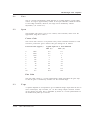
Type
0°C
100°C
200°C
400°C
600°C
1000°C
K
Nickel Chromium/Nickel Aluminium
0
4.1
8.13
16.4
24.91
41.31
J
Iron/Constantan
0
5.37
10.95
22.1
33.67
-
T
Copper/Constantan
0
4.28
9.20
21.0
-
-
Table 1
10
Thermocouple types referenced to 0°C (millivolts)
©1996
Micro Movements Ltd.
M1064 High Gain Amplifier
M1064 HIGH GAIN AMPLIFIER
CONTENTS
1
Description
2
2
Front Panel Controls
2
2.1
2.2
2.3
2.4
3
3
4
4
3
4
©1996
Zero
Span
Tape
Mode
Internal controls
4
3.1
3.2
4
5
Bridge Completion
Low Noise Operation
Sensor Excitation
5
4.1
4.2
5
5
Transducer Supply
Zero Balance Range
5
Voltage Output Range
6
6
Specification
6
7
Typical Input Circuits
7
8
Calibration
8
8.1
9
Micro Movements Ltd.
Calibration Procedure
1
M1064 High Gain Amplifier
M1064 HIGH GAIN AMPLIFIER
1
Description
M1064 is a differential input instrumentation amplifier, featuring a wide bandwidth. It
is designed for use with most types of low level sensors, strain gauges in 1, 2 or 4
active arm configurations, bonded and unbonded strain gauge transducers, load
cells and other sensing devices. It accepts a full range of inputs from 1mV to 1.0 V
and provides gains of up to 2000. The module features an output suitable to drive
galvanometers and a seperately buffered voltage output to drive tape recorders,
oscilloscopes, loggers and data acquisition systems
2
Front Panel Controls
Zero
Span (Coarse Gain)
Span (Fine Gain)
Tape
Mode
Figure 1
2
M1064 Front Panel
©1996 Micro Movements Ltd.
M1064 High Gain Amplifier
2.1
Zero
This is a 15-turn potentiometer which functions as a bridge balance or input offset
control. Its range is approximately ± 20mV at the input terminals (±4000 microstrain
at 10V bridge excitation). This control is disabled when in the 'CAL' mode.
2.2
Span
The amplifier span (gain) is set by two controls, coarse and fine, which cover the
approximate range 0.5 to 1000. The additional buffered voltage outpput provides an
additional gain of up to 2.
Coarse Gain
The Coarse Gain control is a 10-position rotary switch calibrated such that in each
successive position the gain is halved. The gain settings are shown including the
additional buffered voltage output which incorporates a 2:1 adjustment on the fine
gain and a 2:1 adjustment on the tape control. The full range is as follows:
Position
Max Gain
0
2000
1
1000
2
500
3
250
4
125
5
62
6
31
7
16
8
8
9
4
Maximum Dynamic range = 1 Volt at input
Min Gain
500
250
125
62
31
16
8
4
2
1
Fine Gain
The Fine Gain control is a 15-turn potentiometer which interpolates the gain steps
so that the gain is continuously variable over the switched range. The control gives
a 2:1 adjustment and is effective for the complete amplifier, that is both the galvo
output and the voltage output.
2.3
©1996
Tape
Micro Movements Ltd.
3
M1064 High Gain Amplifier
A separate amplifier is incorporated to give a buffered voltage output from the unit
to drive oscilloscopes, tape recorders, etc. via the Voltage Output connector located
on the cabinet rear panel. This is adjustable by means of a 15-turn potentiometer on
the module front panel up to ± 10 Volts dc.
2.4
Mode
A toggle switch enables the amplifier to be used easily in the Operational or the
Calibration mode.
In the Operation (RUN) position the amplifier input terminals are directly connected
to the transducer via pins 4 and 5 on the Signal Input Connector (see section 8).
In the Calibration (CAL) position the input is connected to a DC calibration voltage
derived from the recorder or signal conditioning cabinet being used.
* Note
When used in the 'CAL' position, the front panel 'Zero' control is disabled. The 'CAL'
zero is preset on an internal adjustment.
3
Internal controls
3.1
Bridge Completion
The amplifier may be used with resistive bridge networks in the 1, 2 or 4 arm mode.
In the 1 or 2 arm mode bridge completion is achieved by connecting dummy bridge
arms within the amplifier by means of an internal switch (SW2).
The switch is a 6-pole 2-position type, of which poles 1, 2 and 3 are concerned with
bridge conditioning. The dummy bridge arms should be switched in according to the
input configuration, as follows:
Full Bridge:In this case the bridge is completed within the transducer, therefore
poles 1, 2 and 3 should be in the Open position.
Half Bridge:Poles 1 and 2 are Closed, bringing in the two 499 ohm dummy arms.
Pole 3 remains Open.
Quarter Bridge: Poles 1, 2 and 3 are Closed. Note that closing Pole 3 brings in
R26, which is normally 350 ohms. If the resistance of the single external bridge arm
is different from this value R26 must be changed to match it. (See also Typical Input
Circuits).
3.2
4
Low Noise Operation
©1996 Micro Movements Ltd.
M1064 High Gain Amplifier
To minimise output noise at high gains a low pass filter can be switched in by
closing Poles 4 and 5 of SW2. This has the effect of reducing the bandwidth to
approximately 9KHz.
4
Sensor Excitation
4.1
Transducer Supply
The 3 - 12V DC transducer supply is generated by the mainframe and appears on
pins 1 and 2 of the amplifier. These are connected (via R29 and R30) to pins 3 and
4, which in turn are connected to pins 1 and 2 on the 7-pin Signal Input Connector
at the rear of the instrument. Thus the transducer cannot be energised unless there
is an amplifier present in that particular channel.
Note that the amplifier is normally supplied with R1 and R2 replaced by wire links so
that the full supply (3 - 12V DC as selected by the Bridge Volts switch) appears
across the transducer. However, if a reduced supply is required on a particular
channel these may be replaced by resistors of the appropriate value to act as
droppers in the supply lines.
For example:
With 10V excitation selected, a particular strain gauge is
required to be energised with 2.5V.
Bridge resistance = 350 ohms
Bridge excitation = 2.5V
Volt drop required = 7.5V
Therefore:
R29 + R30 = (350x7.5)/2.5 = 1050 ohms
So R29 and R30 are 525 ohms each.
Provision is also made to reverse the excitation polarity by means of links, (A or B),
on the board, or of course this may also be achieved by reversing pins 1 and 2 on
the Signal Input connector.
4.2
Zero Balance Range
Bridge balance is set by a 22-turn potentiometer which has a nominal range of
±20mV at the input (±4000 microstrain for 10V bridge excitation).
5
©1996
Voltage Output Range
Micro Movements Ltd.
5
M1064 High Gain Amplifier
The amplifier has a separate buffered voltage output which appears on the Voltage
Output socket on the rear of the instrument. The nominal output can be adjusted by
means of the potentiometer marked Fine Gain to between ±5V and ±10V maximum
output swing.For certain applications, such as driving a Tape Recorder, it may be
necessary to limit the output swing to ±2V. This may be achieved by closing Pole 6
of SW2, which attenuates the output by 5:1. The Tape adjustment can then be used
for fine tuning.
6
Specification
Input Configuration:
Input Impedance:
Input Mode:
Input Range:
Zero Offset Range
Maximum Input:
Common Mode Rejection:
Noise: (Up to 10KHz)
Drift:
Bandwidth: (-3dB)
Bandwidth: (-1dB)
Gain:
Output (Voltage):
Output impedance (Voltage):
Output (Galvo)
Output Impedance (Galvo):
Package:
7
6
High Gain Differential
1 Megohm Differential
1) Resistive bridge in 1, 2 or 4 arm connection with
internal bridge completion.
2) Low level signals generally.
Up to 1 V (approx.)
+/- 20mV r.t.i
15V D.C.
90dB (D.C. to 60 Hz)
Less than 5 microvolts r.m.s.(r.t.i.) at max. gain.
Less than 2 microvolts/°C (r.t.i.) at max. gain.
100Khz at Max gain
50KHz at max gain
1 to 2000 in switched steps with interpolate control.
Up to ±10V DC
0.5 ohms
±10mA into 120 ohms
250 ohms
Standard M1000 series module
Typical Input Circuits
©1996 Micro Movements Ltd.
M1064 High Gain Amplifier
Figure 2
Strain Gauge
1
2
3
4
5
6
7
1
2
3
4
5
6
7
Strain Gauge (1/2 Bridge)
Strain Gauge (1/4 Bridge)
1
2
3
4
5
6
7
Strain Gauge (Full Bridge)
Figure 3
Analogue Signals
1
2
3
4
5
6
7
Analogue Signals
Figure 4
High Voltage
2
Earth
8
3
C104
1
1
2
3
4
5
6
7
Calibration
A true calibration of any system can only be achieved by applying a known physical
©1996
Micro Movements Ltd.
7
M1064 High Gain Amplifier
stimulus to the sensor, for example, if the sensor is a pressure transducer, by the
use of a deadweight tester, or, in the case of a load cell, by applying known
weights, etc.
The Micro Movements mainframe calibrator works by removing the output
connections from the transducer and injecting a known DC voltage into the amplifier
input which corresponds to the signal produced by the transducer for a given
stimulus, this being determined by reference to the manufacturers test certificate for
that transducer.
Confusion is sometimes caused during the calibration procedure due to the
apparent zero shift produced by the different operating modes. It is important for the
user to understand why this may occur and how to correct for it. There are basically
three zero modes to consider:
a)
The galvanometer zero - That is, the true mechanical zero when no current is
flowing through the coil. The best way to determine this is to switch the
supply to the amplifier off and then the galvanometer may be rotated so that
the spot is focused at the point on the chart where the zero for that particular
channel is required. The Galvo. On/Off switch is used for this purpose.
b)
The amplifier zero - The M1064 module has a variable zero, which is
controlled by the potentiometer marked Zero. In practice the amplifier zero
should be made coincident with the galvanometer zero by the use of this
control. Switch the mode switch on the amplifier to Cal and the Ch. No./Cal
switch on the recorder to Ch. No. The meter should now read 0.00V.
c)
The sensor zero - Virtually all sensors, except some self-generating types,
have a residual zero offset, that is an output which is present when no
physical stimulus is applied by the system under test. This may be due to the
sensor itself, e.g. mis-match between strain gauges in a Wheatstone bridge,
or to physical effects. e.g. an accelerometer would have an output equivalent
to 1g in the vertical plane, an absolute pressure transducer would have an
output equivalent to ambient barometric pressure, etc. or a combination of
both these conditions. This offset can be nulled by the amplifier zero control.
Note 1)
When the transducer is disconnected a zero offset is observed which
has the opposite polarity to the sensor offset.
Note 2)
When using the 'CAL' mode on the M1064 the zero offset is supressed
(the zero control has no effect) to obtain an output proportional to calibration
voltage only.
d)
8
If a sensor is calibrated in the laboratory and then taken out and mounted on
the system under test there may be a difference in the zero due to a change
in the temperature or mounting stresses, etc., and this should simply be
nulled off as in c) above, the calibration is normally unaffected.
©1996 Micro Movements Ltd.
M1064 High Gain Amplifier
Mode Switch (Amplifier)
This is a 2-pole changeover switch connected to the amplifier input terminals.
8.1
•
In the Operation (RUN) position the amplifier input is connected directly to the
signal source (usually a transducer) via pins 4 and 5 on the Signal Input
connector at the rear of the instrument.
•
In the Calibration (CAL) position the input is connected to a calibration
voltage derived from the recorder or signal conditioning cabinet.
Calibration Procedure
A typical example calibration procedure for one channel would be as follows:
Take a pressure transducer with a nominal output of 40mV for full scale pressure
with 10V excitation (typical for an unbonded strain gauge type). However, it is
unlikely that any particular transducer would have an output of exactly 40mV, more
likely it would be somewhere within ±10% of this value. So, we look at the
manufacturers calibration certificate supplied with the transducer and see that this is
a 75 PSI unit which has an output of +38.68mV at 75 PSI if energised with a 10V
DC supply.
Note: If energised by a different supply the output is normally pro-rata but the
temperature coefficient is sometimes degraded.
The transducer has a zero imbalance (i.e. an output when no pressure is applied) of
-2.97mV. Therefore the total output change for 75 PSI applied is the sum of these
two (because the zero imbalance happens to be negative):
38.68 + 2.97 = 41.65mV.
Preset the controls as follows:
M1064 Front Panel Controls
Zero Balance Potentiometer
©1996
Micro Movements Ltd.
*
9
M1064 High Gain Amplifier
Range Switch :
5
Fine Gain
Fully Counter-clockwise
Tape Control
Fully Counter-clockwise
Run/Cal Switch
Cal
DIP Switch
1
Half Bridge
OFF
2
Half Bridge
OFF
3
Quarter Bridge
OFF
4
Low Pass Filter
OFF
5
Low Pass Filter
OFF
6
+/- 2 V limit
OFF
Mainframe Monitor Unit Controls
Monitor Range Switch
19.99
Monitor Ch. No./Cal Switch
Cal
Galvo. On/Off
OFF
Channel
N
Bridge Voltage
(as required for transducer)
10V
Bridge On/Off
OFF
Calibrate +/OFF/+
Calibrate Fine
*
Calibrate Range
10V
*
Not Important
N
Corresponding to channel being calibrated
Note: This feature is not fitted to M1000-6.
1)
Using the Calibrate FINE potentiometer set the voltage on the Monitor to
4.17V.
2)
Turn Calibrate RANGE to 100mV. There will now be 41.7mV on the
mainframe calibration bus.
3)
Recorders only. Use the galvanometer tool to rotate the galvanometer to
align the spot to position 11 on the viewing scale.
Note: If all channels are not in use, it is preferable to use the centre channels for
the best optical fidelity.
10
4)
Galvo. ON/OFF switch to ON. (This switch provides power to the amplifiers.)
Calibrate +/OFF/- switch to OFF
Monitor CH. No./CAL switch to CH. No.
5)
You should read 0.00V on the monitor. {For recorders, also observe the
galvo. spot, it should correspond to the position set in 3) i.e. 11. If there is a
discrepancy, recheck, as either the amplifier is faulty or there has been a
©1996 Micro Movements Ltd.
M1064 High Gain Amplifier
wrong setting.}
6)
Calibrate +/OFF/- switch to +.
For recorders, adjust the spot deflection to 7.5cm. using the FINE gain
control on the amplifier.
For amplifier housings only adjust the fine control fully clockwise.
7)
Using the TAPE potentiometer on the amplifier, set the monitor voltage to a
suitable value, e.g. 2.00V. At this stage the system has been calibrated for a
sensitivity of 1cm/10 PSI on the recorder and a voltage output of 200mV per
10 PSI.
8)
Calibrate +/OFF/- switch to OFF.
Check that zero is still true
9)
RUN/CAL switch on the amplifier to RUN.
Check that zero is still true
10)
Bridge ON/OFF switch to ON
The zero will almost certainly move due to residual offset. Use the Zero
control to reset the output shown on the Monitor to 0.00V. For recorders this
should correspond to the spot in the original zero position, i.e. 11 on the
graticule
11)
The system is now fully calibrated and ready for use. For recorders, if a
different position is preferred for the galvo. mechanical zero, set the Galvo.
ON/OFF switch to the OFF position before moving the galvo. Return the
switch to ON after the galvo. has been set.
Note If, after step 10), the galvo. or voltmeter are completely off scale note the
position of the range switch and temporarily reduce the gain of the amplifier
by turning the range switch counter-clockwise one or two positions until the
monitor voltage reduces and/or the spot is visible and then re-balance. If it
still cannot be re-balanced there must be a fault in the bridge circuit, all four
arms of the bridge should be checked at the free connector.
©1996
Micro Movements Ltd.
11
M1064 High Gain Amplifier
12
©1996 Micro Movements Ltd.
M1070 Attenuator Amplifier
M1070 ATTENUATOR/AMPLIFIER
CONTENTS
1
Description
2
2
Front Panel Controls
2
2.1
2.2
2.3
2.4
3
3
3
3
3
4
©1996
Shift
Range
Tape
Mode
Internal controls
4
3.1
3.2
3.3
4
4
4
Bridge Completion
Low Noise Operation
Ground Reference
Sensor Excitation
5
4.1
4.2
5
5
Transducer Supply
Zero Balance Range
5
High Voltage Operation
5
6
Specification
6
7
Typical Input Circuits
6
8
Calibration
8
8.1
9
Micro Movements Ltd.
Calibration Procedure
1
M1070 Attenuator Amplifier
M1070 ATTENUATOR/AMPLIFIER
1
Description
The M1070 is a general purpose attenuator/low-gain amplifier module for operation
with high level sensors such as DC/DC LVDTs, servo accelerometers, etc. and
signals generally in the 25mV to 100V range. (For high voltage measurements a
special attenuator plug is available, see documentation on C104 High Voltage
Connector.)
Features include high input impedance, low noise and drift, with input protection up
to 125V differential.
2
Front Panel Controls
Shift
Range (Coarse)
Range (Fine)
Tape
Mode
Figure 1
2
M1070 Front Panel
©1996
Micro Movements Ltd.
M1070 Attenuator Amplifier
2.1
Shift
This is a 22-turn potentiometer which acts as a back-off or input offset control
enabling the output to be shifted over plus and minus full scale.
2.2
Range
The gain/attenuation range of the amplifier is set by two controls, coarse and fine,
which cover the range; divide by 100 to multiplied by 100.
Coarse Gain
The coarse control is a 5-position rotary switch calibrated directly in gain, the actual
sensitivity obtained being a function of the galvanometer type:
Indicated Range
“100
“10
x1
x10
x100
* see section 5
Typical Input Voltage for 5cm deflection
Max. (fine gain
Min. (fine gain
fully counter-clockwise)
fully clockwise)
*
75V
75V
7.5V
7.5V
750mV
750mV
75mV
75mV
7.5mV
Fine Gain
The Fine Gain control is a 15-turn potentiometer which interpolates the gain steps
so that the gain is continuously variable over the switched range.
2.3
Tape
A separate amplifier is incorporated to give a buffered voltage output from the unit to
drive oscilloscopes, tape recorders, etc. via the Voltage Output connector located
on the cabinet rear panel. This is adjustable by means of a 15-turn potentiometer on
the module front panel up to ±2V DC.
2.4
Mode
A toggle switch enables the amplifier to be used easily in the Operational or the
Calibration mode.
In the Operation (RUN) position the amplifier input terminals are directly connected
to the transducer via pins 4 and 5 on the Signal Input Connector (see section 8).
In the Calibration (CAL) position the input is connected to a DC calibration voltage
derived from the recorder or signal conditioning cabinet being used.
©1996
Micro Movements Ltd.
3
M1070 Attenuator Amplifier
3
Internal controls
3.1
Bridge Completion
The amplifier may be used with resistive bridge networks in the 1, 2 or 4 arm mode.
In the 1 or 2 arm mode, bridge completion is achieved by connecting dummy arms
within the amplifier by means of an internal switch (SW2).
The switch is a 6-pole 2-position type, of which poles 1, 2 and 3 are concerned with
bridge conditioning, as follows:
Full Bridge: In this case the bridge is completed within the transducer, therefore
poles 1, 2 and 3 should be in the Open or OFF position.
Half Bridge: Poles 1 and 2 are ON, bringing in two 499 ohm dummy arms (R1 and
R2). Pole 3 remains Open.
Quarter Bridge: Poles 1, 2 and 3 are ON. Note that closing Pole 3 brings in R3,
which is normally 120 ohms. If the resistance of the single external bridge arm is
different from this value R3 must be changed to match it. (See Typical Input
Circuits)
3.2
Low Noise Operation
To minimise output noise at high gains a low pass filter can be switched in by
closing Poles 4 and 5 of SW2. This, however, has the effect of reducing the
bandwidth to approximately 150Hz.
3.3
Ground Reference
In applications where the signal source has no connection to ground, (e.g. battery
operated systems), it may be desirable to connect the Input LO of the amplifier to
ground internally for best noise performance. Pole 6 of SW2 gives this connection
when switched to the ON position.
4
©1996
Micro Movements Ltd.
M1070 Attenuator Amplifier
4
Sensor Excitation
4.1
Transducer Supply
The 3 - 12V DC transducer supply (M1015) appears on pins 1 and 2 of the amplifier.
These are connected (via R1 and R2) to pins 3 and 4, which in turn are connected to
pins 1 and 2 on the 7-pin Signal Input Connector at the rear of the instrument. Thus
the transducer cannot be energised unless there is an amplifier present in that
particular channel. Note that the amplifier is normally supplied with R1 and R2
replaced by wire links so that the full supply (3 - 12V DC as selected by the Bridge
Volts switch) appears across the transducer. However, if a reduced supply is
required on a particular channel these may be replaced by resistors of the
appropriate value to act as droppers in the supply lines.
For example:
With 10V excitation selected, a particular strain gauge is
required to be energised with 2.5V.
Bridge resistance = 120 ohms
Bridge excitation = 2.5V
Volt drop required = 7.5V
Therefore:
R1 + R2 = (120x7.5)/2.5 = 360 ohms
So R1 and R2 are 180 ohms each.
Provision is also made to route out the amplifier power supply rails by selection of
links (B) on the board. These connect the +12V rail to pin 3, the 0V rail to pin 9 and
the -12V rail to pin 4. These in turn are connected to the Signal Input connector on
pins 1, 6 and 2 respectively.
Amplifiers supplied from the factory with this connection are designated M1070/S11
and are marked with two brown dots on the handle.
4.2
Zero Balance Range
Bridge balance is set by a 22-turn potentiometer which has a nominal range of
±20mV at the input (±4000 microstrain for 10V bridge excitation). For transducers
with a very large residual imbalance the range of this control may be increased by
the adjustment of R10.
5
High Voltage Operation
A special connector, type C104, with a built-in balanced attenuator can be used to
extend the input range up to 250V r.m.s. (See documentation on C104 High Voltage
Connector).
©1996
Micro Movements Ltd.
5
M1070 Attenuator Amplifier
6
Specification
Input Configuration:
Input Impedance:
Input Mode:
Low Gain Differential
220 Kohm Differential
1) Resistive bridge in 1, 2 or 4 arm connection with
internal bridge completion.
2) Medium/high level signals generally.
Up to 500 mV (approx.)
125V D.C. (up to 250V r.m.s with adaptor type
Input Range:
Maximum Input:
C104)
Noise:
Drift:
Bandwidth:
Gain:
Less
Less
D.C.
“100
Output (Voltage):
Output impedance (Voltage):
Output (Current)
Output Impedance (Current):
Package:
7
than 20 microvolts r.m.s.(r.t.i.).
than 20 microvolts/°C (r.t.i.).
- 10KHz.
- x100 in 5 switched steps with interpolate
control.
Up to ±10V DC
0.5 ohms
±10mA into 120 ohms
250 ohms
Standard M1000 series module
Typical Input Circuits
1
2
3
4
5
6
7
Analogue Signals
Figure 2
Analogue Signals
2
Earth
Figure 3
6
C104
1
3
1
2
3
4
5
6
7
High Voltage
©1996
Micro Movements Ltd.
M1070 Attenuator Amplifier
1
2
3
4
5
6
7
Potentiometric
Figure 4
Potentiometric
1
2
3
4
5
6
7
Resistance Thermometer
Figure 5
Resistance Thermometer
1
2
3
4
5
6
7
DC/DC LVDT
Figure 6
©1996
Micro Movements Ltd.
DC/DC LVDT
7
M1070 Attenuator Amplifier
8
Calibration
A true calibration of any system can only be achieved by applying a known physical
stimulus to the sensor, for example, if the sensor is a pressure transducer, by the
use of a deadweight tester, or, in the case of a load cell, by applying known weights,
etc. The M1016 calibrator works by removing the output connections from the
transducer and injecting a known DC voltage into the amplifier input which
corresponds to the signal produced by the transducer for a given stimulus, this
being determined by reference to the manufacturers test certificate for that
transducer.
Confusion is sometimes caused during the calibration procedure due to the
apparent zero shift produced by the different operating modes. It is important for the
user to understand why this may occur and how to correct for it. There are basically
three zero modes to consider:
a)
The galvanometer zero - That is, the true mechanical zero when no current is
flowing through the coil. The best way to determine this is to switch the
supply to the amplifier off and then the galvanometer may be rotated so that
the spot is focused at the point on the chart where the zero for that particular
channel is required. The Galvo. On/Off switch is used for this purpose.
b)
The amplifier zero - The M1060 module has a variable zero, which is
controlled by the potentiometer marked Zero. In practice the amplifier zero
should be made coincident with the galvanometer zero by the use of this
control. Switch the mode switch on the amplifier to Cal and the Ch. No./Cal
switch on the recorder to Ch. No. The meter should now read 0.00V. Adjust
using the Zero potentiometer.
c)
The sensor zero - Virtually all sensors, except some self-generating types,
have a residual zero offset, that is an output which is present when no
physical stimulus is applied by the system under test. This may be due to the
sensor itself, e.g. mis-match between strain gauges in a Wheatstone bridge,
or to physical effects. e.g. an accelerometer would have an output equivalent
to 1g in the vertical plane, an absolute pressure transducer would have an
output equivalent to ambient barometric pressure, etc. or a combination of
both these conditions. This offset can be nulled by the amplifier zero control,
as in b) above.
There are two further considerations regarding the zero condition:
8
d)
If a sensor is calibrated in the laboratory and then taken out and mounted on
the system under test there may be a difference in the zero due to a change
in the temperature or mounting stresses, etc., and this should simply be
nulled off as in b) above, the calibration is normally unaffected.
e)
When the amplifier is switched from Run to Cal mode there may be a zero
shift due to a change in the input conditions. This can be nulled as before
without any effect on the calibration.
©1996
Micro Movements Ltd.
M1070 Attenuator Amplifier
8.1
Calibration Procedure
A typical calibration procedure for one channel would be as follows:
Example
It is required to calibrate the recorder for a 1.000 volts input to give 10cm deflection
on the galvanometer and 2.00 volts on the Tape output.
Preset the controls as follows:
M1070 Front Panel Controls
Shift Potentiometer
*
Range Switch
x 10
Fine Gain
Fully Counter-clockwise
Tape Control
Fully Counter-clockwise
Mode Switch
Cal
6-Pole DIP switch
1
Half Bridge
OFF
2
Half Bridge
OFF
3
Quarter Bridge
OFF
4
150 Hz low pass filter
OFF
5
150 Hz low pass filter
OFF
6
Ground Input Lo
OFF
Monitor Unit Controls
Monitor Range Switch
1.999
Monitor Ch. No./Cal switch
Cal
Galvo. On/Off switch
OFF
Channel
N
Bridge Voltage
*
Bridge On/Off
OFF
Calibrate +/OFF/+
Calibrate Fine
*
Calibrate Range
1V
*
Not Important
N
Corresponds to channel being calibrated
Note: On the M12-150A the Galvo. On/Off switch is fitted inside the Signal
Conditioning access hatch on top of the instrument. This feature is not fitted
to M1000-6.
Some versions of the M1070 have a higher gain than others and in this case
the range switch should be in the X1 position to give the correct gain for the
example.
©1996
Micro Movements Ltd.
9
M1070 Attenuator Amplifier
1)
Use the Calibrate FINE potentiometer to set the Cal voltage to 1.000 volts on
the monitor.
2)
Recorders only - Use the galvanometer tool to rotate the galvanometer to
align the spot to position 11 on the viewing scale.
Note: If all channels are not in use it is preferable to use the centre channels for the
best optical fidelity, e.g. Channels 3 through to 7.)
3)
Set the Galvo. ON/OFF switch to ON. (This switch provides power to the
amplifiers.)
Set the Calibrate +/OFF/- switch to OFF
Set the Monitor CH. No./CAL switch to CH. No.
Set the Monitor 1.999/19.99 switch to 19.99
4)
Adjust the SHIFT potentiometer on the amplifier to give 0.00V on the monitor.
Observe the galvo, it should correspond to the position set in 2), i.e. 11. If
there is a discrepancy recheck the procedure, as either the amplifier is faulty
or there has been a wrong setting.
5)
Set the Calibrate +/OFF/- switch to +. For recorders use the FINE gain
control on the amplifier to set the galvo. spot to position 1, i.e. a deflection of
10cm from 11.
6)
Use the TAPE potentiometer on the amplifier to set the monitor voltage to
2.00 volts. At this stage, the system has been calibrated for a sensitivity of
10cm/volt on the recorder and 2.00 volts/volt on the voltage output.
7)
Set the Calibrate +/OFF/- swtich to OFF. If there has been a change from the
original setting of 11 on the chart scale or 0.00V on the monitor repeat the
above procedure from the original preset values in order to fine tune the
system.
8)
Set the RUN/CAL switch on the amplifier to RUN. The recorder will now read
directly the voltage at the input connector scaled as in 7).
If the galvo. spot is off scale, turn the range switch on the amplifier to x 1. This will
reduce the original setting by a factor of 10, thus indicating the input voltage as
calibrated x 10.
10
©1996
Micro Movements Ltd.
M1073 R.M.S./D.C. Converter
M1073 R.M.S./D.C. CONVERTER
CONTENTS
©1996
1
Description
2
2
Front Panel Controls
2
2.1
2.2
2.3
2.4
3
3
3
3
Shift
Volts
Tape
Mode
3
Functional Description
4
4
High Voltage Operation
4
5
Specification
4
6
Typical Input Circuits
5
7
Calibration
6
7.1
6
Micro Movements Ltd.
Calibration Procedure
1
M1073 R.M.S./D.C. Converter
M1073 R.M.S./D.C. CONVERTER
1
Description
The M1073 is an R.M.S./D.C. Converter that accepts AC inputs in the range 10mV
r.m.s. to 100V RMS and provides a DC signal to the galvanometer and tape
outputs. Typical inputs would be from current transformers, tape replay amplifiers,
50/60Hz and 400Hz power lines, etc. (see also section 4).
2
Front Panel Controls
Shift
Volts (Coarse)
Volts (Fine)
Tape
Mode
Figure 1
2
M1073 Front Panel
©1996
Micro Movements Ltd.
M1073 R.M.S./D.C. Converter
2.1
Shift
This is a 22-turn potentiometer which acts as a back-off or input offset control
enabling the output to be shifted over plus and minus full scale on the chart.
2.2
Volts
The gain/attenuation range of the amplifier is set by two controls, coarse and fine,
which cover the range 10mV to 100V r.m.s..
Coarse
The coarse control is a 5 position switch calibrated directly in volts.
Indicated Range
Typical input voltage range for 5cm deflection with
M1600 type galvanometer
Max. (fine control
Min. (fine
control
fully counter-clockwise)
fully clockwise)
0.01V
45mV
4mV
0.1V
450mV
40mV
1V
4.5V
400mV
100V
*
40V
* The input voltage cannot exceed 125V r.m.s.. It is however, often necessary to
reduce the deflection to less than full scale for the maximum of 125V r.m.s.. (See
High Voltage Operation).
Fine
The fine interpolation control covers a 10:1 range.
2.3
Tape
A separate amplifier is incorporated to give a buffered voltage output from the unit
to drive oscilloscopes, tape recorders, etc. via the Voltage Outputs connector
located on the cabinet rear panel. This is adjustable by means of a 15-turn
potentiometer on the front panel to give up to 2V DC output.
2.4
Mode
A toggle switch enables the amplifier to be used easily in the Operational or the
Calibration mode.
In the Operation (RUN) position the amplifier input terminals are directly connected
to the transducer via pins 4 and 5 on the Signal Input Connector (see section 7).
In the Calibration (CAL) position the amplifier is connected directly to the AC
calibration signals on pins 15 and 16 of the amplifier connector.
©1996
Micro Movements Ltd.
3
M1073 R.M.S./D.C. Converter
The AC calibration is connected to the 13.8V AC 50Hz transformer winding and
therefore is limited in application.
For accurate calibration, an external signal generator and AC reading digital voltmeter are
necessary.
3
Functional Description
The module consists of an attenuator followed by a differential amplifier. The output of the
differential amplifier feeds a precision rectifier which is followed by a two pole Butterworth
Filter. The filter is set to give 1% ripple on a 50Hz signal.
4
High Voltage Operation
A special connector, type C104, with a built in balanced attenuator can be used to extend
the input range up to 250V r.m.s. (See documentation for C104 High Voltage Attenuator).
5
Specification
Input Range:
Input Frequency:
Input Impedance:
Attenuator (Coarse):
Attenuator (Fine):
Output (Voltage):
Output Impedance (Voltage):
Output (Current):
Output Impedance: (Current)
Maximum Input:
Linearity:
6
4
10mV to 100V r.m.s.
50Hz to 10kHz
220k ohms differential
5 positions; 10mV, 100mV, 1V, 10V, 100V
Interpolates 10:1 range
Up to ±10V DC
0.5 ohms
±10mA into 30 ohms
250 ohms
100V r.m.s.
±0.5%
Typical Input Circuits
©1996
Micro Movements Ltd.
M1073 R.M.S./D.C. Converter
Figure 2
Analogue Signals
1
2
3
4
5
6
7
Analogue Signals
Figure 3
Current Transformer
1
2
3
4
5
6
7
Current Transformer
Figure 4
High Voltage
2
Earth
7
©1996
3
C104
1
1
2
3
4
5
6
7
Calibration
Micro Movements Ltd.
5
M1073 R.M.S./D.C. Converter
8
©1996
Micro Movements Ltd.
M1079 Isolated Attenuator Amplifier
M1079 ISOLATED ATTENUATOR/AMPLIFIER
CONTENTS
©1996
1
Description
2
2
Front Panel Controls
2
2.1
2.2
2.3
2.4
3
3
3
3
Shift
Range
Tape
Mode
3
Internal controls
4
4
Sensor Excitation
4
4.1
4.2
4
4
Transducer Supply
Zero Balance Range
5
High Voltage Operation
4
6
Specification
4
7
Typical Input Circuits
5
8
Calibration
6
8.1
7
Micro Movements Ltd.
Calibration Procedure
1
M1079 Isolated Attenuator Amplifier
M1079 ATTENUATOR/AMPLIFIER
1
Description
The M1079 is a general purpose isolated attenuator/amplifier module for operation
with voltage inputs in the range 10mV to 100V. (For high voltage measurements a
special attenuator plug is available, see documentation on C103 and C104 High
Voltage Connector.)
Features include high input impedance, low noise and drift, with galvanic isolation
on the inputs.
2
Front Panel Controls
Shift
Range (Coarse)
Range (Fine)
Tape
Mode
Figure 1
2
M1079 Front Panel
©1996
Micro Movements Ltd.
M1079 Isolated Attenuator Amplifier
2.1
Shift
This is a 22-turn potentiometer which acts as a back-off or input offset control
enabling the output to be shifted over plus and minus full scale.
2.2
Range
The gain/attenuation range of the amplifier is set by two controls, coarse and fine,
which cover the range; divide by 100 to multiplied by 100.
Coarse Gain
The coarse control is a 5-position rotary switch calibrated directly in gain, the actual
sensitivity obtained being a function of the galvanometer type:
Indicated Range
“100
“10
x1
x10
x100
* see section 5
Typical Input Voltage for 5cm deflection
Max. (fine gain
Min. (fine gain
fully counter-clockwise)
fully clockwise)
*
75V
75V
7.5V
7.5V
750mV
750mV
75mV
75mV
7.5mV
Fine Gain
The Fine Gain control is a 15-turn potentiometer which interpolates the gain steps
so that the gain is continuously variable over the switched range.
2.3
Tape
A separate amplifier is incorporated to give a buffered voltage output from the unit
to drive oscilloscopes, tape recorders, etc. via the Voltage Output connector located
on the cabinet rear panel. This is adjustable by means of a 15-turn potentiometer on
the module front panel up to ±10V DC.
2.4
Mode
A toggle switch enables the amplifier to be used easily in the Operational or the
Calibration mode.
In the Operation (RUN) position the amplifier input terminals are directly connected
to the input via pins 4 and 5 on the Signal Input Connector (see section 8).
In the Calibration (CAL) position the input is connected to a DC calibration voltage
derived from the recorder or signal conditioning cabinet being used.
©1996
Micro Movements Ltd.
3
M1079 Isolated Attenuator Amplifier
3
Internal Controls
None available on this module
4
Sensor Excitation
4.1
Transducer Supply
Not available on this module
4.2
Zero Balance Range
Bridge balance is set by a 22-turn potentiometer which has a nominal range of
±10V at the output.
5
High Voltage Operation
A special connector, types C103 or C104, with a built-in balanced attenuator can be
used to extend the input range up to 250V r.m.s. (See documentation on C103/
C104 High Voltage Connector).
6
Specification
Input Configuration:
Input Impedance:
Maximum Input:
Isolated Differential
> 2Mohm Differential
100V D.C.
Noise:
Less than 20 µV +4µV
Drift:
Gain:
Less than 20 µ/°C (r.t.i.).
÷100 - x100 in 5 switched steps with interpolate
control.
± 10 V at output
2 KHz (10KHz maximum)
1000 V
> 60dB
> 100dB
Up to ± 10V DC
0.5 ohms
±10mA into 120 ohms
250 ohms
Standard M1000 series module
Offset
Bandwidth
Isolation Voltage
CMRR
IMRR
Output (Voltage):
Output impedance (Voltage):
Output (Galvo)
Output Impedance (Galvo):
Package:
4
©1996
Micro Movements Ltd.
M1079 Isolated Attenuator Amplifier
7
Typical Input Circuits
1
2
3
4
5
6
7
Analogue Signals
Figure 2
Analogue Signals
2
Earth
C104
1
3
Figure 3
1
2
3
4
5
6
7
High Voltage
7.1. Input Connections
7 Pin Din Connector
PIN NO
1
2
3
4
5
6
7
©1996
Micro Movements Ltd.
FUNCTION
Not Connected
Not Connected
Not Connected
Input Low
Input High
Isolated Ground
Earth
5
M1079 Isolated Attenuator Amplifier
8
Calibration
A true calibration of any system can only be achieved by applying a known physical
stimulus to the sensor, for example, if the sensor is a pressure transducer, by the
use of a deadweight tester, or, in the case of a load cell, by applying known
weights, etc. The M1016 calibrator works by removing the output connections from
the transducer and injecting a known DC voltage into the amplifier input which
corresponds to the signal produced by the transducer for a given stimulus, this
being determined by reference to the manufacturers test certificate for that
transducer.
Confusion is sometimes caused during the calibration procedure due to the
apparent zero shift produced by the different operating modes. It is important for the
user to understand why this may occur and how to correct for it. There are basically
three zero modes to consider:
a)
The galvanometer zero - That is, the true mechanical zero when no current is
flowing through the coil. The best way to determine this is to switch the
supply to the amplifier off and then the galvanometer may be rotated so that
the spot is focused at the point on the chart where the zero for that particular
channel is required. The Galvo. On/Off switch is used for this purpose.
b)
The amplifier zero - The M1060 module has a variable zero, which is
controlled by the potentiometer marked Zero. In practice the amplifier zero
should be made coincident with the galvanometer zero by the use of this
control. Switch the mode switch on the amplifier to Cal and the Ch. No./Cal
switch on the recorder to Ch. No. The meter should now read 0.00V. Adjust
using the Zero potentiometer.
c)
The sensor zero - Virtually all sensors, except some self-generating types,
have a residual zero offset, that is an output which is present when no
physical stimulus is applied by the system under test. This may be due to the
sensor itself, e.g. mis-match between strain gauges in a Wheatstone bridge,
or to physical effects. e.g. an accelerometer would have an output equivalent
to 1g in the vertical plane, an absolute pressure transducer would have an
output equivalent to ambient barometric pressure, etc. or a combination of
both these conditions. This offset can be nulled by the amplifier zero control,
as in b) above.
There are two further considerations regarding the zero condition:
6
d)
If a sensor is calibrated in the laboratory and then taken out and mounted on
the system under test there may be a difference in the zero due to a change
in the temperature or mounting stresses, etc., and this should simply be
nulled off as in b) above, the calibration is normally unaffected.
e)
When the amplifier is switched from Run to Cal mode there may be a zero
shift due to a change in the input conditions. This can be nulled as before
without any effect on the calibration.
©1996
Micro Movements Ltd.
M1079 Isolated Attenuator Amplifier
8.1
Calibration Procedure
A typical calibration procedure for one channel would be as follows:
Example
It is required to calibrate the recorder for a 1.0 volts input to give 10cm deflection on
the galvanometer and 10.0 volts on the Tape output.
Preset the controls as follows:
M1079 Front Panel Controls
Shift Potentiometer
Range Switch
Fine Gain
Tape Control
Mode Switch
*
x 10
Fully Counter-clockwise
Fully Counter-clockwise
Cal
Monitor Unit Controls
Monitor Range Switch
1.999
Monitor Ch. No./Cal switch
Cal
Galvo. On/Off switch
OFF
Channel
N
Bridge Voltage
*
Bridge On/Off
OFF
Calibrate +/OFF/+
Calibrate Fine
*
Calibrate Range
1V
*
Not Important
N
Corresponds to channel being calibrated
Note: On the M12-150A the Galvo. On/Off switch is fitted inside the Signal
Conditioning access hatch on top of the instrument. This feature is not fitted
to M1000-6.
Some versions of the M1079 have a higher gain than others and in this case
the range switch should be in the X1 position to give the correct gain for the
example.
1)
Use the Calibrate FINE potentiometer to set the Cal voltage to 1.000 volts on
the monitor.
2)
Recorders only - Use the galvanometer tool to rotate the galvanometer to
align the spot to position 11 on the viewing scale.
Note: If all channels are not in use it is preferable to use the centre channels for the
best optical fidelity, e.g. Channels 3 through to 7.)
©1996
Micro Movements Ltd.
7
M1079 Isolated Attenuator Amplifier
3)
Set the Galvo. ON/OFF switch to ON. (This switch provides power to the
amplifiers.)
Set the Calibrate +/OFF/- switch to OFF
Set the Monitor CH. No./CAL switch to CH. No.
Set the Monitor 1.999/19.99 switch to 19.99
4)
Adjust the SHIFT potentiometer on the amplifier to give 0.00V on the monitor.
Observe the galvo, it should correspond to the position set in 2), i.e. 11. If
there is a discrepancy recheck the procedure, as either the amplifier is faulty
or there has been a wrong setting.
5)
Set the Calibrate +/OFF/- switch to +. For recorders use the FINE gain
control on the amplifier to set the galvo. spot to position 1, i.e. a deflection of
10cm from 11.
6)
Use the TAPE potentiometer on the amplifier to set the monitor voltage to
2.00 volts. At this stage, the system has been calibrated for a sensitivity of
10cm/volt on the recorder and 2.00 volts/volt on the voltage output.
7)
Set the Calibrate +/OFF/- swtich to OFF. If there has been a change from the
original setting of 11 on the chart scale or 0.00V on the monitor repeat the
above procedure from the original preset values in order to fine tune the
system.
8)
Set the RUN/CAL switch on the amplifier to RUN. The recorder will now read
directly the voltage at the input connector scaled as in 7).
If the galvo. spot is off scale, turn the range switch on the amplifier to x 1. This will
reduce the original setting by a factor of 10, thus indicating the input voltage as
calibrated x 10.
8
©1996
Micro Movements Ltd.
M1080 Frequency/D.C. Converter
M1080 FREQUENCY/D.C. CONVERTER
CONTENTS
©1996
1
Description
2
2
Front Panel Controls
2
2.1
2.2
2.3
2.4
3
3
3
3
Shift
Volts
Tape
Mode
3
Internal Controls
4
4
Tranducer Excitation
5
5
Photo-Electric Pick-Ups
5
6
Offset Zero
5
7
Specification
6
8
Typical Input Circuits
7
9
Calibration
8
9.1
8
Micro Movements Ltd.
Calibration Procedure
1
M1080 Frequency/D.C. Converter
M1080 FREQUENCY/D.C. CONVERTER
1
Description
The M1080 Frequency/DC Converter produces a DC output signal proportional to
the frequency of the input signal. The input may be a dynamic waveform from 10mV
r.m.s. to 100V r.m.s.. Applications include flow measurement (impeller flowmeters),
photo-electric and magnetic shaft speed sensors and AC tachometers.
2
Front Panel Controls
Shift
Range (Coarse)
Range (Fine)
Tape
Mode
Figure 1 M1080 Front Panel
2
©1996
Micro Movements Ltd.
M1080 Frequency/D.C. Converter
2.1
Shift
This is a 22-turn potentiometer which acts as a back-off or output offset control on
the current output, enabling the output to be shifted over plus or minus full scale
output.
2.2
Volts
The frequency range over which the unit will operate is determined by two controls,
coarse and fine.
Coarse
The coarse control is a rotary switch calibrated directly in input frequency.
Typical Deflection of M1600 galvanometer:
Position of fine
gain potentiometer
Fully clockwise
Fully counter-clockwise
Input Frequency
As indicated on
range switch
55cm
5cm
20% of indicated
range
11cm
1cm
Fine
The fine control is a 15-turn potentiometer with a 5:1 range which interpolates the
switched steps.
2.3
Tape
A 15-turn potentiometer is used to adjust the voltage output of the amplifier
independent of the galvanometer output. The tape voltage output can be used to
drive recorders, oscilloscopes, digital voltmeters or other voltage driven devices.
The output voltage is adjustable up to 2V DC.
2.4
Mode
A toggle switch enables the amplifier to be used easily in the Operational or the
Calibration mode.
In the Operation (RUN) position the amplifier input terminals are directly connected
to the transducer via pins 4 and 5 on the Signal Input Connector (see section 7).
In the Calibration (CAL) position the input is connected to a calibration signal. The
source of this calibration signal is described in section 3.
©1996
Micro Movements Ltd.
3
M1080 Frequency/D.C. Converter
3
Internal Controls
A 6-pole dual-in-line (DIL) switch (SW2) is mounted on the printed circuit board, this
switch is accessible through a cut-out in the side of the amplifier cover.
SW2/1 (Optional Offset)
An optional offset can be fitted to the Frequency to DC Converter. This is of value
for measuring variations on a fixed frequency, e.g. frequency variations of 50/60Hz
power lines or 400Hz aircraft supplies. This is a factory fitted option designated
M1080/S33 and can be identified by two orange dots on the handle. See the section
titled Offset Zero.
SW2/2, 3 and 4 (Filter Time Constant)
Range
Filter Time Constant
Poles
Pole
Poles
Poles
2, 3, 4 open 2 closed
2, 3 closed
2, 3, 4 closed
OFF
10 kHz
75mS
35mS
15mS
5mS
2kHz
300mS
140mS
60mS
20mS
500Hz
1.5S
700mS
300mS
100mS
100Hz
7.5S
3.5S
1.5S
500mS
The units are dispatched with poles 2, 3 and 4 open, i.e. the longest time constant.
Other combinations of filtering can be achieved by a combination of the 3 poles of
SW2 being utilised.
SW2/5 and 6 (Internal/External Cal.)
The calibration is normally internal with SW2/5 closed and SW2/6 open. In this case
the calibration is derived from the power supply frequency, i.e. 50/60Hz or 400Hz
when used on DC power. (This calibration facility is of limited value for operation at
frequencies above 1kHz.)
A crystal-controlled frequency calibrator is available, the M1085, which has 9
calibration frequencies from 20Hz to 10kHz. When an M1085 is fitted the calibration
signal is available on pin 16 of all the modules and can be switched to the
Calibration Input of the M1080 by closing SW2/6 and opening SW2/5.
Note: If poles 5 and 6 are both closed, damage will not occur but the result will be
incorrect.
4
©1996
Micro Movements Ltd.
M1080 Frequency/D.C. Converter
4
Tranducer Excitation
The ±12V power supply can be routed through the module to the rear panel of the
recorder thus providing excitation for optical pick-ups, etc. (M1080/S9).
5
Photo-Electric Pick-Ups
It is common for PEP outputs to be unidirectional. Pins are provided for an offset to
the input so that the input is driven by a unidirectional signal. e.g. If the input is a TTL
compatible positive square wave, connect a 47k ohms resistor across D4, thus
giving a -2V bias to the input.
6
Offset Zero
Many applications require an offset zero facility e.g. in monitoring 50Hz or 400Hz
power supplies to record a deviation of ±10%.
The DIL switch position 1 provides an offset zero when closed. The value of the
offset is controlled by AOT resistor R23 and potentiometer VR4. In the offset mode,
it is not always possible to obtain the required gain in the system, e.g. ±10% is only
one fifth of the normal output. A provision to increase the gain is provided by R12.
R12 - Normally open circuit
R12 - 4k7 (Increases gain by 2)
R12 - 2k2 (Increases gain by 3)
R12 - 1k2 (Increases gain by 5)
Note: Further gain increases will reduce the stability of the system.
©1996
Micro Movements Ltd.
5
M1080 Frequency/D.C. Converter
7
Specification
Input Configuration:
Input Impedance:
Input Mode:
Input Range:
Maximum Input:
Drift:
Bandwidth:
Full Scale Range:
Output Voltage:
Output Impedance (Voltage):
Output Current:
Output Impedance (Current):
Filters:
Shift:
Package:
6
Single ended
10k ohms
1) Sinewave from impeller flowmeters,
RPM pick-ups, etc.
2) Square wave TTL.
10mV to 100V r.m.s.
100V r.m.s. (up to 250V r.m.s. with C104 adaptor).
±0.01%/°C Referred to Output
1Hz to 10Hz
Off, 10kHz, 2kHz, 500Hz, 100Hz with interpolate
control.
Up to ±10V DC
0.5 ohms
±10mA into 120 ohms
250 ohms
From 5 mS to 7.5S
(See Filter Time Constant Table.)
±10mA on current output
Standard M1000 series module.
©1996
Micro Movements Ltd.
M1080 Frequency/D.C. Converter
8
Typical Input Circuits
1
2
3
4
5
6
7
Impeller Flowmeter
Figure 2
Impeller Flowmeter
1
2
3
4
5
6
7
1
2
3
4
5
6
7
R.P.M. Pick-Up (Photo-Electric)
Figure 3
R.P.M. Pick-Up (Magnetic)
R.P.M. Pick-up
1
2
3
4
5
6
7
Analogue Signals
Figure 4
Analogue Signals
2
Earth
Figure 5
©1996
Micro Movements Ltd.
C104
1
3
1
2
3
4
5
6
7
High Voltage
7
M1080 Frequency/D.C. Converter
9
Calibration
To achieve accurate calibration an M1085 Frequency Calibrator must be used.
9.1
Calibration Procedure
The module is to be calibrated to give 10cm deflection corresponding to a flow rate
of 100 gallons/minute. A voltage output of 2.00 volts is required for the same scale.
An impeller flowmeter is used with a calibration factor of 1105Hz for 125gpm.
The corresponding frequency for 100gpm = (100/125) x 1105 = 884Hz.
The nearest calibration frequency on the M1085 is 500Hz.
The deflection for a 500Hz signal would be 10 x (500/884) = 5.65cm.
Preset the Controls as Follows:
M1080 Front Panel
Shift Control
*
Range Switch
2kHz
Fine Gain
*
Tape Control
*
Run/Cal Switch
CAL
6-pole DIP Switch
1
Optional Offset
OFF
2
Filter
OFF
3
Filter
OFF
4
Filter
OFF
5
Line Freq. Cal.
OFF
6
M1085 Cal.
ON
M1085 Front Panel
Range Switch
OFF
Monitor Front Panel
Range Switch
1.999
Ch. No./Cal. Switch
Ch. No.
Galvo. On/Off Switch
OFF
Channel
N
Bridge Voltage
*
Bridge On/Off
OFF
Calibrate +/OFF/*
Calibrate Fine
*
Calibrate Range
*
*
Not important
N
Corresponding to channel being calibrated.
8
©1996
Micro Movements Ltd.
M1080 Frequency/D.C. Converter
Note: On the M12-150 the Galvo. On/Off switch is fitted inside the Signal
Conditioning access hatch on top of the instrument. This feature is not fitted to
M1000-6.
©1996
1)
Recorders only. Use the galvanometer tool to rotate the galvanometer to align
the spot to position 11 on the viewing scale.
2)
Set the Galvo. ON/OFF Switch to ON. Use the Shift control to adjust the
voltage to 0.00V on the monitor. This should correspond to the spot at
position 11 on the viewing scale. If not, repeat step 1).
3)
Set the M1085 RANGE to 0.5kHz. Adjust the FINE gain control on the M1080
to deflect the spot by 5.65 cm on the viewing scale, i.e. Position 11 - 5.65 =
5.45.
4)
Adjust the TAPE control to read 1.130V on the monitor.
5)
It is useful to check linearity at this stage. Set the M1085 RANGE switch to
200Hz.
The deflection should be (200/500) x 5.65 = 2.26cm.
Scale reading = 11 - 2.26 = 8.74cm
Monitor reading = (200/500) x 1.130 = 0.452V
6)
Set the RUN/CAL switch on the M1080 to RUN. The system is now calibrated
and ready for use.
7)
It is advisable to return the M1085 RANGE switch to OFF.
Micro Movements Ltd.
9
M1080 Frequency/D.C. Converter
10
©1996
Micro Movements Ltd.