1
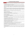
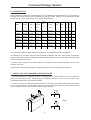
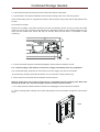
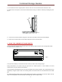
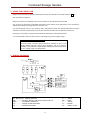
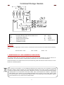
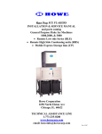
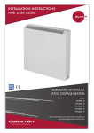
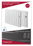
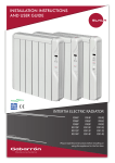
INSTALLATION INSTRUCTIONS
AND USER GUIDE
IECEE
CB
SCHEME
COMBINED STORAGE HEATERS
CSH12
CSH18
CSH24
CSH12A
CSH18A
CSH24A
Please read these instructions before installing or
using this appliance for the first time
Combined Storage Heaters 1.- WARNING
•
•
•
•
•
•
•
•
•
•
•
•
•
•
•
•
•
•
•
•
Please read these instructions before installing or using this appliance for the first time. The warranty of the
combined storage heater will not cover any damage caused by non observance of any of these instructions.
This Guide must be kept and given to any new owner.
This appliance can be used by children aged from 8 years and above and persons with reduced physical,
sensory or mental capabilities or lack of experience and knowledge if they have been given supervision or
instruction concerning use of the appliance in a safe way and understand the hazards involved. Children must
not play with the appliance. Cleaning and user maintenance must not be made by children without
supervision.
Children aged from 3 years and less than 8 years shall only switch on/off the appliance provided that it has
been placed or installed in its intended normal operating position and they have been given supervision or
instruction concerning use of the appliance in a safe way and understand the hazards involved. Children aged
from 3 years and less than 8 years shall not plug in, regulate and clean the appliance or perform user
maintenance.
Neither the connecting cable nor any other object must come into contact with the hot unit.
Check that the voltage shown on the rating plate on the heater is the same as the voltage of the supply to
which connection is to be made.
WARNING: In order to avoid overheating, do not cover the heater. Do not use this heater to dry clothes. Do
not place objects in contact with the heater.
The installation of the heater should be carried out by qualified electricians.
Should the heater be moved and reinstalled it is essential that the work is carried out by qualified electricians.
Never open a charged heater.
If during any reinstallation the thermal insulation shows any sign of damage, it is necessary for the faulty part
to be removed and replaced by an identical part.
The use of storage heaters is forbidden in any area where there is a presence of gases, explosives or
inflammable objects.
The air outlet grill at the top of the heater cabinet and the air inlet at the bottom of the heater are provided to
ensure the most efficient operation of the appliance. They also protect the heater from overheating; therefore,
it is essential that at no time are they covered.
This heater should be switched off at the isolating switch before any repair work is carried out. This action
should also be taken during the times of the year when heat is not required.
The installation of the heaters must be carried out in such a way that each pole can be disconnected from the
supply having a contact separation of at least 3 mm.
The storage heater should not be installed just below an electrical socket.
The appliance must be installed in such a way that it is impossible for anyone using a bath or shower, to touch
the controls. This appliance must be earthed.
The nominal charging time of this storage heater must be controlled by means of a programmer.
The installation must be carried out in accordance with the current electrical regulations.
After installation a survey of the first charging cycle should be carried out to ensure that the main input
thermostat switches off. Ventilate the room during this first cycle.
Before carrying out any work inside the appliance, the heater must be disconnected from the electricity supply.
• The presence in the air of particles of smoke, dust and other pollutants could, in time, discolour the walls and
•
surfaces around the heater.
To maintain stability, it is essential that the heater is placed on a level surface and care should be taken to
avoid irregular surfaces, such as may result from carpets or tiled surrounds partially protruding under the
heater.
2 Combined Storage Heaters 2.- INTRODUCTION
Storage heaters are designed to take advantage of the considerable economical benefits of any restricted hour
electricity tariff. These heaters consume electricity only during the night, but due to the highly efficient storage
medium, give you a truly economical 24 hours of comfort temperatures.
Max.
Hours
Model
Voltage
Input
Convector
Charge
Bricks
Weight
L
W
H
kg
cm
cm
cm
54
18.5
73
76.5 18.5
73
on
V
kW
kW
kWh
CSH12
230/240
1.6/1.7
0.9/1.0
8/7
12.8 /11.9
8
80
CSH18
230/240
2.4/2.55
1.4/1.5
8/7
19.2/17.85
12
117
CSH24
230/240
3.2/3.4
1.6/1.75
8/7
25.6/23.8
16
154
99
18.5
73
CSH12A
230/240
1.6/1.7
0.9/1.0
8/7
12.8 /11.9
8
80
54
18.5
73
CSH18A
230/240
2.4/2.55
1.4/1.5
8/7
19.2/17.85
12
117
76.5 18.5
73
CSH24A
230/240
3.2/3.4
1.6/1.75
8/7
25.6/23.8
16
154
99
18.5
73
The input control operates a highly sensitive thermostat which regulates the amount of heat stored.
The discharge is by convection heat which can be partially controlled by use of the output control. It is important
that the correct rating of heater is installed to provide the selected level of heat. This will ensure the best possible
running costs against other fuels.
To reduce transport problems, the heater casings and storage bricks are packed separately. The bricks are
packed in sets of two.
You should be aware that Storage heaters, when fully charged, can have high surface temperatures.
3.- INSTALLING THE COMBINED STORAGE HEATER 1.- Chose the right place to install the heater. It is necessary that a minimum clearance of 50 cm is allowed to
ensure the best heating results. Always maintain a minimum clearance of 50 cm from the heater to any
combustible materials such as furniture and curtains.
2.- Open the carton at the indicated side and fix the feet (fig 1) without removing the heater casing). The screws
are in the accessories bag. Turn the carton upside down to allow the heater to stand on its feet and remove the
carton. Check that it is the correct model and that it is in good condition.
Fig.1
3 Combined Storage Heaters 3.- Take off the front panel by removing the two screws at the bottom of the heater.
4.- Set the heater in the selected installation area and mark the fixing points on the wall using a pencil.
Use the heater fixing holes as a template and mark the wall through the fixing holes. Drill the required holes into
the wall.
Fix the heater to the wall.
Please note the weight of the heater is taken by the feet, the wall fixing screws are only to prevent the heater
overturning. If there is any doubt as to the strength of the wall please consult an expert. Storage heaters are very
heavy and the installer must ensure that they are securely fixed and that there is no possibility of them
overturning.
Fig.2
5.- Connect the heater using the enclosed wiring diagram. Ensure that all connections are firm.
The “restricted supply” leads must be connected to a supply controlled by means of a programmer.
The “unrestricted supply” leads must be connected to a 24 hours supply. Use silicone covered wire.
Do not leave any remaining wire inside the heater. Do not connect the convector element yet.
6.- Remove the inner front panel with the attached convector element.
Warning. At the other side of this front panel there is a breakable thermal insulation panel. Both sides
must be handle with care. Avoid touching the insulation and the convector element.
7.- Do not disconnect the electrical elements. Remove the packaging then lift and recline the elements.
8.- Place the storage bricks carefully, with the flat side facing the back of the heater. Arrange two rows of bricks
(fig 3).
Fig.3
4 Combined Storage Heaters 9.- Fix the elements in their original position. Place the other two rows of bricks with the knobs face to face.
10.- Refit the inner front panel. If the bricks have been fitted correctly you will find no difficulty in refitting the panel
(fig 4).
Fig.4
11.- Connect the convector element using the two free fast-on terminals. Follow the enclosed diagram.
12.- Attach the front panel and fix it at the bottom edge with the two screws provided.
4.- USING THE COMBINED STORAGE HEATER The two controls at the right top of the heater govern the input and output functions of the storage heater. Both
are printed with the numbers 1 to 5.
Fig.5
The input control allows you to select the amount of heat you wish to store during the night.
During mild weather, it is normal to set your input control in a medium position. In cooler weather, the control
could be set at 5 to give maximum heat retention.
The stored heat will be delivered to the room by both radiant and convected methods. The convected heat can be
regulated by using the output control. This control governs the continuous flow of convected heat from the outlet
grill.
All combined storage heaters have an exclusive feature which makes it unnecessary to close the output control at
night. The outlet grill will close automatically at the beginning of the overnight charge
5 Combined Storage Heaters 5.- USING THE CONVECTOR Switch on the convector by setting the switch placed at the lower left side of the heater marked – o to “-“.
The off position is marked “0”.
When the convector is generating heat, the neon indicator on the switch will be illuminated.
The convector is fitted with an adjustable thermostat, which enables room temperature to be controlled by
adjusting the setting accordingly when the convector is on.
Turn the thermostat control to the maximum (fully clockwise) and when the desired temperature has been
reached, turn the thermostat slowly to the left (anti-clockwise) until the luminous indicator switches off.
By leaving in this position, the heater will automatically maintain the selected temperature.
It is recommended to switch off the convector at the beginning of the overnight charge.
Models CSH12A, CSH18A and CSH24A:
The direct acting convector element should be switched off prior to the
storage heaters night time charge period engaging. This is to avoid the
possibility of the automatic charge regulator reducing the total charge taken,
due to it reading a high room temperature.
6.- WIRING DIAGRAMS
R1, R2, R3, R4…Heating elements
CE……........Convector element with built in thermal cut out
RAC………...Accelerating resistance
Tc…………...Charge control thermostat
Ta…………...Ambient thermostat
6 C…….. Switch
PE…….Earth
L……….Phase
N……...Neutral
Ts……..Safety cut out
Combined Storage Heaters R1, R2, R3, R4…Heating elements
CE……........Convector element with built in thermal cut out
RAC………...Accelerating resistance
Tc…………...Charge control thermostat
Ta…………...Ambient thermostat
Tl…………….Temperature limiter
C…….. Switch
PE…….Earth
L……….Phase
N……...Neutral
Ts……..Safety cut out
IMPORTANT
This equipment is supplied with a main connector. All the wires must be coloured in accordance with the following
code:
Green & Yellow – Earth
Blue – Neutral
Brown - Live.
7.- MAINTENANCE OF YOUR COMBINED STORE HEATER
This storage heater does not require any special care. During the first few charges you may be aware of an
unusual odour. This is normal and if it happens please ventilate the room until the odour disappears.
If dust accumulates on the heater surface it can be removed using a wet cloth when the heater is cold. Do not use
solvents or a abrasive products.
The symbol on the product or in its packaging indicates that this product may not be treated as household
waste. Instead it shall be handed over to the applicable collection point for the recycling of electrical and
electronic equipment. By ensuring this product is disposed of correctly, you will help prevent potential negative
consequences for the environment and human health, which could otherwise be caused by inappropriate
waste handling of this product. For more detailed information about recycling of this product, please contact
your local city office, your household waste disposal service or the shop where you purchased the product.
These instructions are only valid in the EU member states.
7 ELNUR UK Ltd.
Unit 1, Brown Street North
Leigh, Lancashire
WN7 1BU
www.elnur.co.uk
Customer Service Department:
Telephone +44(0)1942 670119
[email protected]
Manufactured by:
ELNUR, S.A.
Madrid, Spain
www.elnur-global.com
[email protected]
Management System International Certifications:
As a part of the policy of continuous product improvement Elnur reserves the right to alter specifications without notice.
INSTALLATION INSTRUCTIONS AND USER GUIDE WEB VERSION