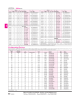
1
USB-Blaster Download Cable
User Guide
101 Innovation Drive
San Jose, CA 95134
http://www.altera.com
UG-USB81204-2.2
P25-10325-03
Document Version:
Document Date:
2.2
March 2007
Copyright © 2007 Altera Corporation. All rights reserved. Altera, The Programmable Solutions Company, the stylized Altera logo, specific device designations, and all other words and logos that are identified as trademarks and/or service marks are, unless noted otherwise, the trademarks and
service marks of Altera Corporation in the U.S. and other countries. All other product or service names are the property of their respective holders. Altera products are protected under numerous U.S. and foreign patents and pending applications, maskwork rights, and copyrights. Altera warrants
performance of its semiconductor products to current specifications in accordance with Altera's standard warranty, but reserves the right to make
changes to any products and services at any time without notice. Altera assumes no responsibility or liability arising out of the application or use of any information, product, or service described herein except as expressly agreed to in writing by Altera
Corporation. Altera customers are advised to obtain the latest version of device specifications before relying on any published information and before placing orders for products or services.
Printed on recycled paper
ii
Altera Corporation
Contents
Chapter 1. Setting Up the USB-Blaster Download Cable
Introduction ............................................................................................................................................
Device Support .................................................................................................................................
Power Requirements ........................................................................................................................
Software Requirements ...................................................................................................................
Hardware Setup .....................................................................................................................................
Software Setup .......................................................................................................................................
Installing the USB-Blaster Driver ...................................................................................................
Setting Up the USB-Blaster Hardware in the Quartus II Software ...........................................
1–1
1–1
1–1
1–2
1–2
1–3
1–3
1–4
Chapter 2. USB-Blaster Specifications
Overview .................................................................................................................................................
USB-Blaster Connections ......................................................................................................................
Voltage Requirements .....................................................................................................................
Cable-to-Board Connection .............................................................................................................
USB-Blaster Plug Connection .........................................................................................................
Circuit Board Header Connection .................................................................................................
Operating Conditions ...........................................................................................................................
USB-Revision ..........................................................................................................................................
References ...............................................................................................................................................
Altera Corporation
2–1
2–1
2–1
2–2
2–2
2–4
2–4
2–6
2–7
iii
Contents
iv
USB-Blaster Download Cable User Guide
Altera Corporation
About this User Guide
Revision History
The table below displays the revision history for the chapters in this User
Guide.
Date
Version
March 2007
2.2
Update to “Installing the USB-Blaster Driver” section.
July 2006
2.1
Minor update to Chapter 2.
June 2006
2.0
Added USB-Blaster Revision section, updated Figure 2–1, Table 2–1, and
Table 2–7. Added Table 2–6.
December 2004
Changes Made
Update to conditions in Table 2–2.
November 2004
1.1
Re-release.
July 2004
1.0
First publication.
How to Contact
Altera
For the most up-to-date information about Altera® products, refer to the
following table.
Information Type
Contact (1)
Technical support
www.altera.com/mysupport/
Product literature
www.altera.com/literature
Altera literature services
[email protected]
FTP site
ftp.altera.com
Note to table:
(1)
Altera Corporation
You can also contact your local Altera sales office or sales representative.
v
Preliminary
Typographic Conventions
Typographic
Conventions
This document uses the typographic conventions shown below.
Visual Cue
Meaning
Bold Type with Initial
Capital Letters
Command names, dialog box titles, checkbox options, and dialog box options are
shown in bold, initial capital letters. Example: Save As dialog box.
bold type
External timing parameters, directory names, project names, disk drive names,
filenames, filename extensions, and software utility names are shown in bold
type. Examples: fMAX, \qdesigns directory, d: drive, chiptrip.gdf file.
Italic Type with Initial Capital
Letters
Document titles are shown in italic type with initial capital letters. Example: AN
75: High-Speed Board Design.
Italic type
Internal timing parameters and variables are shown in italic type.
Examples: tPIA, n + 1.
Variable names are enclosed in angle brackets (< >) and shown in italic type.
Example: <file name>, <project name>.pof file.
Initial Capital Letters
Keyboard keys and menu names are shown with initial capital letters. Examples:
Delete key, the Options menu.
“Subheading Title”
References to sections within a document and titles of on-line help topics are
shown in quotation marks. Example: “Typographic Conventions.”
Courier type
Signal and port names are shown in lowercase Courier type. Examples: data1,
tdi, input. Active-low signals are denoted by suffix n, e.g., resetn.
Anything that must be typed exactly as it appears is shown in Courier type. For
example: c:\qdesigns\tutorial\chiptrip.gdf. Also, sections of an
actual file, such as a Report File, references to parts of files (e.g., the AHDL
keyword SUBDESIGN), as well as logic function names (e.g., TRI) are shown in
Courier.
1., 2., 3., and
a., b., c., etc.
Numbered steps are used in a list of items when the sequence of the items is
important, such as the steps listed in a procedure.
■
Bullets are used in a list of items when the sequence of the items is not important.
●
•
v
The checkmark indicates a procedure that consists of one step only.
1
The hand points to information that requires special attention.
c
The caution indicates required information that needs special consideration and
understanding and should be read prior to starting or continuing with the
procedure or process.
w
The warning indicates information that should be read prior to starting or
continuing the procedure or processes
r
The angled arrow indicates you should press the Enter key.
f
The feet direct you to more information on a particular topic.
vi
USB-Blaster Download Cable User Guide
Altera Corporation
Preliminary
Chapter 1. Setting Up the
USB-Blaster Download Cable
Introduction
The USB-Blaster™ download cable interfaces to a standard USB PC port.
This cable drives configuration data from the PC to the device. Because
design changes are downloaded directly to the device, prototyping is
easy and multiple design iterations can be accomplished in quick
succession.
Device Support
The USB-Blaster download cable allows you to program and configure
Altera® devices. Specifically, you can do the following:
■
■
■
■
■
Download configuration data to FPGA devices:
●
Stratix® II, Stratix II GX, Stratix GX, and Stratix family of devices
●
Cyclone™ II and Cyclone family of devices
●
APEX™ II and APEX 20K family of devices
●
ACEX® 1K devices
●
Mercury™ devices
●
FLEX™ 10K, FLEX 10KE, and FLEX 10KA family of devices
●
Excalibur™ devices
Download configuration data to User Flash Memory (UFM) devices:
●
MAX® II family of devices
Download configuration data to EEPROM-based devices:
●
MAX 3000 and MAX 7000 family of devices
Perform in-system programming of advanced configuration devices:
●
EPC2, EPC4, EPC8, EPC16, and EPC1441 devices
Perform in-system programming of serial configuration devices:
●
EPCS1, EPCS4, EPCS16, and EPCS64 devices
In addition, the USB-Blaster download cable supports target systems
using 5.0 V TTL, 3.3 V LVTTL/LVCMOS, and single-ended I/O
standards from 1.5 V to 3.3 V.
Power Requirements
The USB-Blaster download cable requires the following power sources:
■
■
Altera Corporation
March 2007
5.0 V from the USB cable
Between 1.5 V and 5.0 V from the target circuit board
1–1
Preliminary
Hardware Setup
Software Requirements
The USB-Blaster download cable is available only for Windows 2000 and
Windows XP systems.
Use the Quartus® II software version 4.0 or later to configure your device.
The USB-Blaster download cable also supports the following:
■
■
■
■
Hardware Setup
Quartus II Programmer (for programming and configuration)
Quartus II SignalTap® II Logic Analyzer (for logic analysis)
Quartus II Programmer (standalone version)
Quartus II SignalTap II logic analyzer (standalone version)
This section describes how to install and set up the USB-Blaster download
cable for device configuration or programming.
1
For plug and header dimensions, pin names, and operating
conditions, see Chapter 2, “USB-Blaster Specifications.”
Connect your USB-Blaster download cable to the circuit board as
instructed below.
1.
Disconnect the power cable from the circuit board.
2.
Connect the USB cable to the USB port on your PC and to the
USB-Blaster port.
3.
Connect the USB-Blaster download cable to the 10-pin header on the
device board. Figure 1–1 shows the USB-Blaster download cable
and the circuit board connector.
1–2
USB-Blaster Download Cable User Guide
Altera Corporation
March 2007
Setting Up the USB-Blaster Download Cable
Figure 1–1. The USB-Blaster Download Cable
TAR
G
BL
AS
SID TER
E
PIN1
ET
SID
E
10-pin Female Connector
(connects to target printed
circuit board 10-pin male
header)
4.
Reconnect the power cable to reapply power to the circuit board.
1
Software Setup
The Found New Hardware wizard may open and prompt you
to install a new hardware driver. Close the wizard and install the
hardware driver using the instructions provided in “Installing
the USB-Blaster Driver” below.
This section describes the following:
■
■
Installing the USB-Blaster driver
Setting up the USB-Blaster hardware in the Quartus II software
Installing the USB-Blaster Driver
This section describes how to install the USB-Blaster driver.
Before you begin the installation, verify the USB-Blaster driver is located
in your directory: \<Quartus II system directory>\drivers\usb-blaster
1
Altera Corporation
March 2007
If the driver is not in your directory, download the USB-Blaster
driver from the Altera web site:
www.altera.com/support/software/drivers
1–3
USB-Blaster Download Cable User Guide
Software Setup
To install the driver, follow the directions below:
1.
Plug in the USB-Blaster download cable to the PC.
2.
On the Found New Hardware Wizard window, click No, not this
time and then click Next to continue.
3.
Select Install from a list of specific location (Advanced) and click
Next to continue.
4.
Select Don’t search. I will choose the driver to install. Click Next.
5.
Select Sound, video and game controllers, and click Next to
continue.
6.
Select Have Disk and browse to the location of the driver on your
system: \<Quartus II system directory>\drivers\usb-blaster. Click
OK.
7.
Select Altera USB-Blaster and click Next to continue.
8.
Click Next to install the driver.
9.
Click Continue Anyway when the Hardware Installation warning
appears.
10. Click Finish in the Completing the Add/Remove Hardware Wizard
window. Reboot your system.
Setting Up the USB-Blaster Hardware in the Quartus II Software
Use the following steps to set up the USB-Blaster hardware in the
Quartus II software:
1.
Start the Quartus II software.
2.
Choose Programmer (Tools menu).
3.
Click Hardware Setup. The Hardware Settings tab of the Hardware
Setup dialog box is displayed (Figure 1–2).
1–4
USB-Blaster Download Cable User Guide
Altera Corporation
March 2007
Setting Up the USB-Blaster Download Cable
Figure 1–2. Hardware Setup Dialog Box
4.
From the drop-down menu, select USB-Blaster [USB-0]
(Figure 1–2).
5.
Click Close to close the Hardware Setup dialog box.
6.
In the Mode list, select the desired mode (Programmer window).
Table 1–1 describes each mode.
1
The USB-Blaster supports the Joint Test Action Group (JTAG),
Passive Serial Programming, and Active Serial modes.
Table 1–1. Programming Modes
Mode
Altera Corporation
March 2007
Mode Description
Joint Test Action Group
(JTAG)
Programs or configures all Altera devices
supported by Quartus II software, excluding
FLEX 6000.
In-Socket Programming
Not supported by the USB-Blaster.
Passive Serial Programming
Configures all Altera devices supported by
Quartus II software excluding MAX 3000 and
MAX 7000 devices.
Active Serial Programming
Programs a single EPCS1, EPCS4, EPCS16, and
EPCS64 serial configuration device.
1–5
USB-Blaster Download Cable User Guide
Software Setup
f
For details about programming devices and creating secondary
programming files, see the Programming & Configuration chapter of the
Introduction to Quartus II Handbook.
For further information, see the Programming module of the Quartus II
online tutorial.
For further information, refer to the following topics in the Quartus II
software Help menu:
■
■
■
■
Changing the Hardware Setup
Programmer Introduction
Overview: Working with Chain Description Files
Overview: Converting Programming Files
1–6
USB-Blaster Download Cable User Guide
Altera Corporation
March 2007
Chapter 2. USB-Blaster
Specifications
Overview
USB-Blaster
Connections
This chapter provides comprehensive information about the
USB-Blaster™ download cable including the following:
■
USB-Blaster connections
●
Voltage requirements
●
Cable-to-board connection
●
USB-Blaster plug connection
●
Circuit board header connection
■
Operating conditions
■
USB-Blaster Revision
The USB-Blaster cable has a USB universal plug that connects to the PC
USB port, and a 10-pin female plug that connects to the circuit board.
Data is downloaded from the USB port on the PC through the
USB-Blaster cable to the circuit board via the connections discussed in
this section.
Voltage Requirements
The USB-Blaster VCC(TRGT) pin must be connected to a specific voltage
for the device being programmed. Connect pull-up resistors to the same
power supply as the USB-Blaster VCC(TRGT). See Table 2–1.
Table 2–1. USB-Blaster VCC(TRGT) Pin Voltage Requirements
(Part 1 of 2)
Device Family
MAX II device
USB-Blaster VCC Voltage Required
As specified by VCCIO of Bank 1
MAX 7000S device
5V
MAX 7000AE and MAX 3000A devices
3.3 V
MAX 7000B device
2.5 V
Stratix, Stratix II, Stratix GX, and Stratix II GX devices
As specified by VCCSEL
Cyclone II, Cyclone, APEX II, APEX 20K, and Mercury devices
As specified by VCCIO
FLEX 10K, FLEX 8000, and FLEX 6000 devices
5V
FLEX 10KE device
2.5 V
Altera Corporation
March 2007
2–1
USB-Blaster Connections
Table 2–1. USB-Blaster VCC(TRGT) Pin Voltage Requirements
FLEX 10KA and FLEX 6000A devices
(Part 2 of 2)
3.3 V
EPC2 device
5 V or 3.3 V
EPC4, EPC8, and EPC16 devices
3.3 V
EPCS1, EPCS4, EPCS16, and EPCS64 devices
3.3 V
Cable-to-Board Connection
A standard USB cable connects to the USB port on the device. Figure 2–1
shows a block diagram of the USB-Blaster download cable.
Figure 2–1. USB-Blaster Block Diagram
USBVCC
VCC
USB
Receptacle
USB Interface
Chip
EPM7064AETC44
Voltage Translator
Circuitry
Pin 1
10-Pin
Female Plug
VCC
I/O
I/Os
I/O
I/O
I/Os
I/O
I/O
I/O
I/O
I/O
USB-Blaster Plug Connection
The 10-pin female plug connects to a 10-pin male header on the circuit
board containing the target device. Figure 2–2 shows the dimensions of
the female plug.
2–2
USB-Blaster Download Cable User Guide
Altera Corporation
March 2007
USB-Blaster Download Cable User Guide
Figure 2–2. USB-Blaster 10-Pin Female Plug Dimensions
0.425 Typ.
10
8
6
4
2
9
7
5
3
1
0.250 Typ.
0.100 Sq.
0.025 Sq.
0.700 Typ.
Dimensions are shown in inches. Spacing between pin centers is 0.1 inches.
Table 2–2 identifies the 10-pin female plug pin names and the
corresponding programming mode.
Table 2–2. USB-Blaster Female Plug Signal Names & Programming Modes
AS Mode
PS Mode
JTAG Mode
Pin
Signal Name
Description
Signal Name
Description
Signal Name
Description
1
DCLK
Clock signal
DCLK
Clock signal
TCK
Clock signal
2
GND
Signal ground
GND
Signal ground
GND
Signal ground
3
CONF_DONE
Configuration done
CONF_DONE
Configuration
done
TDO
Data from
device
4
VCC(TRGT)
Target power supply
VCC(TRGT)
Target power
supply
VCC(TRGT)
Target power
supply
5
nCONFIG
Configuration
control
nCONFIG
Configuration
control
TMS
JTAG state
machine control
6
nCE
Cyclone chip enable
–
No connect
–
No connect
7
DATAOUT
Active serial data out
nSTATUS
Configuration
status
–
No connect
8
nCS
Serial configuration
device chip select
–
No connect
–
No connect
9
ASDI
Active serial data in
DATA0
Data to device
TDI
Data to device
10
GND
Signal ground
GND
Signal ground
GND
Signal ground
Altera Corporation
March 2007
2–3
USB-Blaster Download Cable User Guide
Operating Conditions
1
The circuit board must supply VCC(TRGT) and ground to the
USB-Blaster cable for the I/O drivers.
Circuit Board Header Connection
The circuit board's 10-pin male header, which connects to the USB-Blaster
cable's 10-pin female plug, has two rows of five pins. These pins are
connected to the device’s programming or configuration pins. Figure 2–3
shows the dimensions of a typical 10-pin male header.
Figure 2–3. 10-Pin Male Header Dimensions
Top View
Side View
0.100
0.100
0.025 Sq.
0.235
Dimensions are shown in inches.
Operating
Conditions
Tables 2–3 through 2–5 summarize the maximum ratings, recommended
operating conditions, and DC operating conditions for the USB-Blaster
cable.
Table 2–3. USB-Blaster Cable Absolute Maximum Ratings
Symbol
Parameter
Conditions
VCC(TRGT)
Target supply voltage
With respect to ground
VCC(USB)
Min
Max
Unit
–0.3
5.5
V
USB supply voltage
With respect to ground
–0.5
6.0
V
II
Input current
TDO or dataout
–10.0
10.0
mA
Io
Output current for Rev. A and
Rev. B cable
–20.0
20.0
mA
TCK, TMS, TDI, nCS, nCE
–50.0
50.0
mA
Output current for Rev. C cable
2–4
USB-Blaster Download Cable User Guide
Altera Corporation
March 2007
USB-Blaster Download Cable User Guide
Table 2–4. USB-Blaster Cable Recommended Operating Conditions
Symbol
VCC(TRGT)
Parameter
Conditions
Min
Max
Unit
Target supply voltage, 5.0-V operation
4.75
5.25
V
Target supply voltage, 3.3-V operation
3.0
3.6
V
Target supply voltage, 2.5-V operation
2.375
2.625
V
Target supply voltage, 1.8-V operation
1.71
1.89
V
Target supply voltage, 1.5-V operation
1.43
1.57
V
Max
Unit
0.15
V
Table 2–5. USB-Blaster Cable (Rev. A & B) DC Operating Conditions
Symbol
Parameter
Conditions
Min
VIH
High-level input voltage
VIL
Low-level input voltage
VCC(TRGT) –0.2
VOH
5.0-V high-level output voltage VCC(TRGT) = 4.5 V, IOH = 1 mA
3.3-V high-level output voltage VCC(TRGT) = 3.0 V, IOH = 1 mA
VOL
ICC(USB)
V
4.4
V
2.9
V
2.5-V high-level output voltage VCC(TRGT) = 2.375 V, IOH = 1 mA
2.275
V
1.8-V high-level output voltage VCC(TRGT) = 1.71 V, IOH = 1 mA
1.61
V
1.5-V high-level output voltage VCC(TRGT) = 1.43 V, IOH = 1 mA
1.33
V
5.0-V low-level output voltage
VCC(TRGT) = 5.5 V, IOL = 1 mA
0.125
V
3.3-V low-level output voltage
VCC(TRGT) = 3.6 V, IOL = 1 mA
0.125
V
2.5-V low-level output voltage
VCC(TRGT) = 2.625 V, IOL = 1 mA
0.125
V
1.8-V low-level output voltage
VCC(TRGT) = 1.89 V, IOL = 1 mA
0.125
V
1.5-V low-level output voltage
VCC(TRGT) = 1.57 V, IOL = 1 mA
0.125
V
Operating current (No Load)
(Typical ICC(USB) = 80 mA)
150
mA
Altera Corporation
March 2007
2–5
USB-Blaster Download Cable User Guide
USB-Revision
Table 2–6. USB-Blaster Cable (Rev. C) DC Operating Conditions
Symbol
VIH
Parameter
Conditions
High-level input voltage
Min
Max
Unit
VCC(TRGT) >= 2.0 V
2.0
V
VCC(TRGT) < 2.0 V
VCC(TRGT)
V
VIL
Low-level input voltage
VOH
5.0-V high-level output voltage VCC(TRGT) = 4.5 V, IOH = -10 mA
3.8
V
3.3-V high-level output voltage VCC(TRGT) = 3.0 V, IOH = -8 mA
2.3
V
VCC(TRGT) >= 2.0 V
0.8
VCC(TRGT) < 2.0 V
VOL
ICC(USB)
0
V
V
2.5-V high-level output voltage VCC(TRGT) = 2.375 V, IOH = -6 mA
1.8
V
1.8-V high-level output voltage VCC(TRGT) = 1.71 V, IOH = -4 mA
1.2
V
1.5-V high-level output voltage VCC(TRGT) = 1.43 V, IOH = -2 mA
1.0
V
5.0-V low-level output voltage
VCC(TRGT) = 5.5 V, IOL = 10 mA
3.3-V low-level output voltage
VCC(TRGT) = 3.6 V, IOL = 8 mA
0.7
V
2.5-V low-level output voltage
VCC(TRGT) = 2.625 V, IOL = 6 mA
0.6
V
1.8-V low-level output voltage
VCC(TRGT) = 1.89 V, IOL = 4 mA
0.5
V
1.5-V low-level output voltage
VCC(TRGT) = 1.57 V, IOL = 2 mA
Operating current (No Load)
USB-Revision
(Typical
I
CC(USB)
= 80 mA)
0.8
V
0.4
V
150
mA
Table 2–7 indicates the revision and description of the USB-Blaster.
Table 2–7. USB-Revision
Revision
Descriptions
RoHS Compliant
Rev. A (1)
10-pin female connector is connected to the
USB-Blaster through a ribbon cable.
No
Rev. B
10-pin female connector is connected to the
USB-Blaster through a flexible PCB cable.
No
Rev. C
Hardware upgrade to meet the RoHS
lead-free requirement. 10-pin female
connector is connected to the USB-Blaster
through a flexible PCB cable.
Yes
Note to Table 2–7:
(1)
Revision B and Revision C cable has a "Rev. B" and "Rev. C" marking on the casing.
However, you can identify the Revision A cable if the cable is using a ribbon cable
and does not have the revision marking.
2–6
USB-Blaster Download Cable User Guide
Altera Corporation
March 2007
USB-Blaster Download Cable User Guide
References
For more information on configuration and in-system programmability
(ISP), see the following sources:
■
■
■
■
■
■
■
■
■
■
■
■
Altera Corporation
March 2007
AN 39: IEEE 1149.1 (JTAG) Boundary-Scan Testing in Altera Devices
AN 95: In-System Programmability in MAX Devices
AN 250: Configuring Cyclone FPGAs
Configuring Stratix II Devices chapter in Volume 2 of the Stratix II
Device Handbook
Configuring Stratix and Stratix GX Devices chapter in the Stratix Device
Handbook
Configuring Cyclone II Devices chapter in the Cyclone II Handbook
Serial Configuration Devices Data Sheet
Programming & Configuration chapter in the Introduction to Quartus II
manual
The Programming module of the Quartus II online tutorial
Refer to the following glossary definitions in the Quartus II Help:
●
“USB-Blaster Cable” (general description)
●
“Configuration scheme” (general description)
●
“Programming files” (general description)
Refer to the following procedures in the Quartus II Help:
●
Programming a Single Device or Multiple Devices in JTAG or
Passive Serial Mode
●
Programming a Single Device in Active Serial Programming
Mode
Refer to the following introduction and overview topics in the
Quartus II Help:
●
Programmer Introduction
●
Overview: Working with Chain Description Files
●
Overview: Converting Programming Files
2–7
USB-Blaster Download Cable User Guide
References
2–8
USB-Blaster Download Cable User Guide
Altera Corporation
March 2007