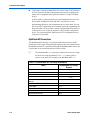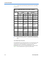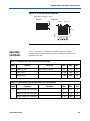
1
ByteBlasterMV Download Cable User Guide
101 Innovation Drive
San Jose, CA 95134
(408) 544-7000
http://www.altera.com
P25-10323-00
Document Version:
Document Date:
1.0
July 2004
Copyright © 2004 Altera Corporation. All rights reserved. Altera, The Programmable Solutions Company, the stylized Altera logo, specific device designations, and
all other words and logos that are identified as trademarks and/or service marks are, unless noted otherwise, the trademarks and service marks of Altera Corporation
in the U.S. and other countries. All other product or service names are the property of their respective holders. Altera products are protected under numerous U.S. and
foreign patents and pending applications, maskwork rights, and copyrights. Altera warrants performance of its semiconductor products to current specifications in accordance with Altera's standard warranty, but reserves the right to make changes to any products and services at any time without notice. Altera assumes no
responsibility or liability arising out of the application or use of any information, product, or service described herein except as expressly agreed
to in writing by Altera Corporation. Altera customers are advised to obtain the latest version of device specifications before relying on any published information and before placing orders for products or services.
Printed on recycled paper
ii
Altera Corporation
Contents
About this User Guide ............................................................................. v
Revision History ........................................................................................................................................... v
How to Find Information .............................................................................................................................. v
How to Contact Altera .................................................................................................................................. v
Typographic Conventions ........................................................................................................................... vi
Abbreviations & Acronyms ........................................................................................................................ vii
Chapter 1. Installing the ByteBlasterMV Download Cable
Introduction .............................................................................................................................................. 1–1
Installation ................................................................................................................................................ 1–1
Installation on a Windows PC ............................................................................................................. 1–1
Installing the Altera ByteBlaster Driver with the BBLPT Utility ................................................. 1–2
Installing the Altera ByteBlaster Driver on Windows NT ............................................................ 1–2
Installing the Altera ByteBlaster Driver on Windows 2000 .......................................................... 1–3
Installing the Altera ByteBlaster Driver on Windows XP ............................................................. 1–4
Installing the ByteBlasterMV Download Cable ............................................................................ 1–6
Installation on a Linux Workstation .................................................................................................... 1–7
Installing the Altera ByteBlaster Kernel Driver for Linux ............................................................ 1–7
Installing the ByteBlasterMV Download Cable on a Linux Workstation ..................................... 1–8
Selecting a Communications Cable for the SignalTap II Logic Analyzer .......................................... 1–9
Chapter 2. ByteBlasterMV Download Cable Data Sheet
Features .....................................................................................................................................................
Functional Description .............................................................................................................................
Download Modes ................................................................................................................................
ByteBlasterMV Connections ..............................................................................................................
ByteBlasterMV Header & Plug Connections ................................................................................
Circuit Board Header Connection ..................................................................................................
Operating Conditions ................................................................................................................................
Software Instructions ................................................................................................................................
Conclusion ................................................................................................................................................
References ................................................................................................................................................
Altera Corporation
2–1
2–1
2–1
2–2
2–3
2–4
2–5
2–6
2–7
2–7
iii
Contents
iv
ByteBlasterMV Download Cable User Guide
Altera Corporation
About this User Guide
Revision History
The table below shows this user guide’s revision history.
ByteBlasterMV Download Cable User Guide Revision History
Date
July 2004
How to Find
Information
You can find more information in the following ways:
■
■
■
■
How to Contact
Altera
Information Type
Technical support
Description
Initial release
The Adobe Acrobat Find feature, which searches the text of a PDF
document. Click the binoculars toolbar icon to open the Find dialog box.
Acrobat bookmarks, which serve as an additional table of contents in PDF
documents.
Thumbnail icons, which provide miniature previews of each page, provide
a link to the pages.
Numerous links, shown in green text, which allow you to jump to related
information.
For the most up-to-date information about Altera products, go to the Altera
world-wide web site at www.altera.com. For technical support on this product,
go to www.altera.com/mysupport. For additional information about Altera
products, consult the sources shown below.
USA & Canada
All Other Locations
www.altera.com/mysupport/
www.altera.com/mysupport/
(800) 800-EPLD (3753)
(7:00 a.m. to 5:00 p.m. Pacific Time)
(408) 544-7000 (1)
(7:00 a.m. to 5:00 p.m. Pacific Time)
Product literature
www.altera.com
www.altera.com
Altera literature services
[email protected] (1)
[email protected] (1)
Non-technical customer
service
(800) 767-3753
(408) 544-7000
(7:30 a.m. to 5:30 p.m. Pacific Time)
FTP site
ftp.altera.com
ftp.altera.com
Note to table:
(1)
You can also contact your local Altera sales office or sales representative.
Altera Corporation
v
Preliminary
Typographic Conventions
Typographic
Conventions
Visual Cue
This document uses the typographic conventions shown below.
Meaning
Bold Type with Initial
Capital Letters
Command names, dialog box titles, checkbox options, and dialog box options are
shown in bold, initial capital letters. Example: Save As dialog box.
bold type
External timing parameters, directory names, project names, disk drive names,
filenames, filename extensions, and software utility names are shown in bold
type. Examples: fMAX, \qdesigns directory, d: drive, chiptrip.gdf file.
Italic Type with Initial Capital
Letters
Document titles are shown in italic type with initial capital letters. Example: AN 75:
High-Speed Board Design.
Italic type
Internal timing parameters and variables are shown in italic type.
Examples: tPIA, n + 1.
Variable names are enclosed in angle brackets (< >) and shown in italic type.
Example: <file name>, <project name>.pof file.
Initial Capital Letters
Keyboard keys and menu names are shown with initial capital letters. Examples:
Delete key, the Options menu.
“Subheading Title”
References to sections within a document and titles of on-line help topics are
shown in quotation marks. Example: “Typographic Conventions.”
Courier type
Signal and port names are shown in lowercase Courier type. Examples: data1,
tdi, input. Active-low signals are denoted by suffix n, e.g., resetn.
Anything that must be typed exactly as it appears is shown in Courier type. For
example: c:\qdesigns\tutorial\chiptrip.gdf. Also, sections of an
actual file, such as a Report File, references to parts of files (e.g., the AHDL
keyword SUBDESIGN), as well as logic function names (e.g., TRI) are shown in
Courier.
1., 2., 3., and
a., b., c., etc.
Numbered steps are used in a list of items when the sequence of the items is
important, such as the steps listed in a procedure.
■
Bullets are used in a list of items when the sequence of the items is not important.
●
•
v
The checkmark indicates a procedure that consists of one step only.
1
The hand points to information that requires special attention.
r
The angled arrow indicates you should press the Enter key.
f
The feet direct you to more information on a particular topic.
vi
Preliminary
Altera Corporation
Abbreviations & Acronyms
Abbreviations &
Acronyms
The following abbreviations and acronyms are used in this document.
Acronym
Altera Corporation
Meaning
AHDL
Altera hardware description language
APU
Altera Programming Unit
CPU
central processing unit
EDA
electronic design automation
IP
intellectual property
LE
logic element
vii
Preliminary
Abbreviations & Acronyms
viii
Preliminary
Altera Corporation
1. Installing the
ByteBlasterMV Download
Cable
Introduction
You can use the ByteBlasterMV™ download cable to do the following:
■
■
■
■
■
Installation
Download configuration data to SRAM-based devices, such as Stratix® II,
Stratix GX, Stratix, CycloneTM II Cyclone, APEXTM II, APEX 20K
(including APEX 20K, APEX 20KE, and APEX 20KC), ACEX® 1K,
MercuryTM , FLEX® 10K (including FLEX 10KA and FLEX 10KE),
FLEX 8000, FLEX 6000, and ExcaliburTM devices.
Download configuration data to EEPROM-based devices, such as MAX® II,
MAX 9000, MAX 7000S, MAX 7000AE, MAX 7000B, and MAX 3000A
Perform in-system programming of advanced configuration (EPC2, EPC4,
EPC8, and EPC16)
Perform SignalTap II logic analysis
Connect the ByteBlasterMV download cable directly to your PC’s parallel
port, a Linux workstation parallel port, or through an Altera Software Guard
that is connected to the parallel port.
The ByteBlasterMV download cable has a 25-pin male header that connects to
the PC parallel port, and a 10-pin female plug that connects to the circuit board.
Data is downloaded from the PC’s parallel port through the ByteBlasterMV cable
to the circuit board via these connections.
This section explains the following procedures:
■
■
■
■
■
Installing the Altera ByteBlasterTM driver with the BBLPT Utility
Installing the Altera ByteBlaster driver on Windows NT
Installing the Altera ByteBlaster driver on Windows 2000
Installing the Altera ByteBlaster driver on Windows XP
Installing the ByteBlasterMV download cable
Installation on a Windows PC
To install the ByteBlasterMV download cable on a Windows PC, you must
perform the following steps, each of which are described in more detail in this
section.
■
■
Altera Corporation
Install the Altera ByteBlaster driver
Install the ByteBlasterMV download cable
1–1
Installation
Installing the Altera ByteBlaster Driver with the BBLPT Utility
The Altera ByteBlaster driver can be installed or removed with the BBLPT
utility. You can use the BBLPT utility with Windows NT, Windows 2000, and
Windows XP. You must install the Altera ByteBlaster driver separately from the
Quartus® II software.
1
You do not need to install the ByteBlasterMV download cable before
installing the Altera ByteBlaster kernel driver, and this installation
requires that you have administration (administrator) privileges.
To install the Altera ByteBlaster driver with the BBLPT utility, follow this step:
v From the \<Quartus II system directory>\drivers\i386 directory, type the
following command at the command prompt:
bblpt /i r
To remove the Altera ByteBlaster driver with the BBLPT utility, follow this step:
v From the \<Quartus II system directory>\drivers\i386 directory, type the
following command at the command prompt:
bblpt /r r
Installing the Altera ByteBlaster Driver on Windows NT
The Altera ByteBlaster driver is required for PCs running Windows NT 4.0 that
use the ByteBlasterMV download cable. You must install the Altera ByteBlaster
driver separately from the Quartus II software.
1
You do not need to install the ByteBlasterMV download cable before
installing the Altera ByteBlaster kernel driver, and this installation
requires that you have administration (administrator) privileges.
To install the Altera ByteBlaster driver for Windows NT, follow these steps:
1
f
1–2
You can also use the BBLPT utility to install the Altera ByteBlaster
driver.
For more information, go to “Installing the Altera ByteBlaster Driver with the
BBLPT Utility” on page 1–2.
1.
Choose Settings > Control Panel (Windows Start menu).
2.
In the Control Panel window, double-click the Multimedia icon.
Altera Corporation
Installing the ByteBlasterMV Download Cable
3.
In the Multimedia Properties dialog box, click the Devices tab, and click
Add.
4.
In the List of Drivers list, select Unlisted or Updated Driver and
click OK.
5.
In the Install Driver dialog box, type <disk drive>:\<Quartus II system
directory>\drivers or select the name with Browse (...) to specify the
Quartus II software drivers directory.
6.
Click OK.
7.
In the Add Unlisted or Updated Driver dialog box, select Altera
ByteBlaster.
8.
To restart your computer, click Restart Now.
Installing the Altera ByteBlaster Driver on Windows 2000
The Altera ByteBlaster driver is required for PCs running Windows 2000 that use
the ByteBlasterMV download cable. You must install the Altera ByteBlaster
driver separately from the Quartus II software.
1
You do not need to install the ByteBlasterMV download cable before
installing the Altera ByteBlaster kernel driver.
1
Installing the Altera ByteBlaster kernel driver requires that you have
administration (administrator) privileges.
To install the Altera ByteBlaster driver for Windows 2000, follow these steps:
1
f
Altera Corporation
You can also use the BBLPT utility to install the Altera ByteBlaster.
For more information, go to “Installing the Altera ByteBlaster Driver with the
BBLPT Utility” on page 1–2.
1.
Choose Settings > Control Panel (Windows Start menu).
2.
In the Control Panel window, double-click the Add/Remove Hardware
icon and click Next.
3.
In the Choose a Hardware Task page of the Add/Remove Hardware
wizard, select Add/Troubleshoot a device and click Next.
4.
In the Choose a Hardware Device page, select Add a new device and
click Next.
1–3
Installation
5.
In the Find New Hardware page, select No, I want to select the
hardware from a list and click Next.
6.
In the Hardware Type page, select Sound, video and game controllers
and click Next.
7.
In the Select a Device Driver page, select Have disk.
8.
Specify the full directory path to the \<Quartus II system
directory>\drivers\win2000 directory with Browse (...), and click OK.
9.
In the Digital Signature Not Found page, click Yes.
10. In the Select a Device Driver page, select either ByteBlaster II or
ByteBlasterMV, and click Next.
11. In the Start Hardware Installation page, click Next.
12. In the Digital Signature Not Found page, click Yes.
13. In the Completing the Add/Remove Hardware Wizard page, click
Finish.
14. To restart your computer, click Restart Now.
Installing the Altera ByteBlaster Driver on Windows XP
The Altera ByteBlaster driver is required for PCs running Windows XP that use
the ByteBlasterMV download cable. You must install the Altera ByteBlaster
driver separately from the Quartus II software.
1
You do not need to install the ByteBlasterMV download cable before
installing the Altera ByteBlaster kernel driver.
1
Installing the Altera ByteBlaster kernel driver requires that you have
administration (administrator) privileges.
To install the Altera ByteBlaster driver for Windows XP, follow these steps:
1
f
1–4
You can also use the BBLPT utility to install the Altera ByteBlaster.
For more information, go to “Installing the Altera ByteBlaster Driver with the
BBLPT Utility” on page 1–2.
1.
Choose Control Panel (Windows Start menu).
2.
Click the Switch to Classic View link.
Altera Corporation
Installing the ByteBlasterMV Download Cable
3.
In the Control Panel window, double-click Add Hardware and click
Next. The Add/Remove Hardware Wizard dialog box appears.
4.
Select Yes, I have already connected the hardware, and click Next.
5.
In the Installed hardware list, select Add a new hardware device and
click Next.
6.
Select Install the hardware that I manually select from a list
(Advanced), and click Next.
7.
Select Sound, video and game controllers, and click Next.
8.
Select Have disk.
9.
Specify the full directory path to the \<Quartus II system
directory>\drivers\win2000 directory with Browse (...), and click OK.
10. In the Digital Signature Not Found page, click Yes. A software
installation warning appears.
11. Click Continue Anyway.
12. Select Altera ByteBlaster and click Next. A hardware installation warning
appears.
13. Click Continue Anyway.
14. Click Finish.
15. When prompted to restart your computer, click Yes.
Installing the ByteBlasterMV Download Cable
To install and set up the ByteBlasterMV parallel port download cable for device
configuration or programming, follow these steps:
1.
Attach the ByteBlasterMV download cable to a parallel port on your PC
and insert the 10-pin female plug into the prototype system containing the
target device, as shown in Figure 1–1.
1
Altera Corporation
The board must supply power to the ByteBlasterMV download cable.
1–5
Installation
Figure 1–1. ByteBlasterMV Parallel Port Download Cable
ByteBlasterMV 10-pin
female plug
ByteB
laster
MV
Computer parallel port
2.
Choose Programmer (Tools menu).
or
Choose New (File menu). Click the Other Files tab, select Chain
Description File, and click OK.
1–6
3.
In the Programmer window, click Hardware. The Hardware Settings tab
of the Hardware Setup dialog box is displayed.
4.
Click Add Hardware. The Add Hardware dialog box is displayed.
5.
In the Hardware type list, select ByteBlaster II or ByteBlasterMV.
6.
In the Port list, select the appropriate port.
7.
Click OK.
Altera Corporation
Installing the ByteBlasterMV Download Cable
Installation on a Linux Workstation
To install the ByteBlasterMV download cable on a Linux workstation, you must
perform the following steps, each of which are described in more detail in this
section:
■
■
Install the Altera ByteBlaster kernel driver on a Linux workstation running
Red Hat Linux versions 7.3 or 8.0, or Red Hat Enterprises Linux version 3.0.
Install the ByteBlasterMV download cable.
Installing the Altera ByteBlaster Kernel Driver for Linux
The Altera ByteBlaster kernel driver is required for Linux workstations running
Red Hat Linux version 7.3 or 8.0, or Red Hat Enterprises Linux version 3.0 that
use the ByteBlasterMV download cable. You must install and compile the Altera
ByteBlaster kernel driver outside of the Quartus II software.
To compile the Altera ByteBlaster kernel driver, you must have the following
Red Hat Package Manager (RPM) packages, which are available from the Red
Hat web site at www.redhat.com:
■
■
■
■
.gcc-2.96-81
.make-3.79.1-5
.binutils-2.10.91.0.2-3
kernel-headers (RPM version must correspond to kernel version)
To verify that an RPM is installed, use the rpm -q <name> r command. For
example, rpm -q gcc r verifies that the gcc RPM is installed.
1
You do not need to install the ByteBlasterMV download cable before
installing the Altera ByteBlaster kernel driver.
1
Installing the Altera ByteBlaster kernel driver requires that you have
administration (administrator) privileges.
To install the Altera ByteBlaster kernel driver for Linux workstations, follow
these steps:
1.
Decompress the byteblaster.tar.gz file by typing the following command
at the command prompt:
tar -xzvf byteblaster.tar.gz r
2.
Altera Corporation
Access the new directory by typing the following command at the
command prompt:
1–7
Installation
cd byteblaster r
3.
Run the configure install script by typing the following command at the
command prompt:
./configure r
4.
Compile the Altera ByteBlaster kernel driver by typing the following
command at the command prompt:
make r
5.
Become root and compile the Altera ByteBlaster kernel driver module and
device nodes by typing the following command at the command prompt:
make install r
Installing the ByteBlasterMV Download Cable on a Linux
Workstation
To install and set up the ByteBlasterMV download cable on a Linux workstation
for device configuration or programming, follow these steps:
1.
Attach the ByteBlasterMV download cable to a parallel port on your Linux
workstation and insert the 10-pin female plug into the prototype system
containing the target device, as shown in Figure 1–2.
1
1–8
The board must supply power to the ByteBlasterMV download
cable.
Altera Corporation
Installing the ByteBlasterMV Download Cable
Figure 1–2. ByteBlasterMV Parallel Port Download Cable Connections
ByteBlasterMV 10-pin
female plug
ByteB
laster
MV
Computer parallel port
2.
To install the Altera ByteBlaster kernel driver, type the following
command at the command prompt:
jtagconfig --add byteblastermv /dev/byteblaster0 r
3.
To determine whether the ByteBlasterMV download cable and the Altera
ByteBlaster kernel driver were installed correctly, display a list of available
devices by the typing the following commands at the command prompt:
jtagconfig r
You should see a list of devices on your JTAG chain, including the
ByteBlasterMV download cable.
Selecting a Communications Cable for the SignalTap II Logic
Analyzer
To select a communications cable for the SignalTap® II Logic Analyzer, follow
these steps.
1.
Choose SignalTap II Logic Analyzer (Tools menu).
The SignalTap window will open.
Altera Corporation
1–9
Installation
2.
Under JTAG Chain Configuration, select ByteBlasterMV in the
Hardware pulldown list.
If the communications cable that you want to use does not appear in the
Hardware list, continue as follows:
f
3.
Under JTAG Chain Configuration, click Setup.
4.
Click Add Hardware in the Hardware Setup dialog box to add a
hardware setup for the communications cable.
For more information about SignalTap II logic analysis with the ByteBlasterMV
download cable, refer to “Selecting the Communications Cable for the
SignalTap II Logic Analyzer” in Quartus II Help.
Ordering code: PL-BYTEBLASTERMV
1–10
Altera Corporation
2. ByteBlasterMV Download
Cable Data Sheet
Features
■
■
■
■
■
■
■
Functional
Description
Allows PC users to perform the following functions:
–
Program MAX® II, MAX 9000, MAX 7000S, MAX 7000AE,
MAX 7000B, MAX 3000A, advanced configuration (EPC2, EPC4,
EPC8, and EPC16)
–
Configure Stratix® II, Stratix GX, Stratix, CycloneTM II, Cyclone,
APEXTM II, APEX 20K (including APEX 20K, APEX 20KE, and
APEX 20KC), ACEX® 1K, MercuryTM , FLEX® 10K (including
FLEX 10KA and FLEX 10KE), FLEX 8000, FLEX 6000, and
ExcaliburTM devices.
Supports target systems using 5.0-V TTL, 3.3-V LVTTL/LVCMOS, and
single-ended I/O standards from 3.3 through 1.8 V.
Provides a fast and low-cost method for in-system programming
Supported by the Altera® Quartus® II development software
Interfaces with a standard 25-pin parallel port on PCs
Uses a 10-pin circuit board connector
Supports SignalTap® II logic analysis in the Quartus II software
The ByteBlasterMV parallel port download cable (ordering code:
PL-BYTEBLASTERMV) interfaces to a standard PC parallel port (also known
as an LPT port). This cable drives configuration data from the PC to Stratix,
Stratix GX, Stratix II, Cyclone, Cyclone II, APEX II, APEX 20K (including
APEX 20K, APEX 20KE, and APEX 20KC), ACEX 1K, Mercury, Excalibur,
FLEX 10K (including FLEX 10KA and FLEX 10KE), FLEX 8000, and
FLEX 6000 devices, as well as programming data to MAX II, MAX 9000,
MAX 7000S, MAX 7000AE, MAX 7000B, MAX 3000A devices, and EPC
configuration devices. Because design changes are downloaded directly to the
device, prototyping is easy and multiple design iterations can be accomplished in
quick succession. See Figure 2–1.
Download Modes
The ByteBlasterMV cable provides two download modes:
■
Altera Corporation
Passive serial mode (PS)—In Passive Serial mode, the Quartus II
Programmer can configure all Altera devices supported by the Quartus II
software except MAX 3000 and MAX 7000 devices, and all programming
options disappear from the Programmer window.
2–1
Functional Description
■
JTAG mode—Industry-standard Joint Test Action Group (JTAG) interface.
In JTAG mode, the Quartus II Programmer can program or configure all
Altera devices supported by the Quartus II software, except FLEX 6000
devices.
In JTAG mode, you add specific devices and configuration devices to the
device chain, in addition to POFs and SOFs, and you have several
programming options for each configuration device in the chain. You can
also verify EPC configuration device contents against its programming file
data, check that a device is blank, examine a programmed device and save
its data to file, or use its data to program or verify another configuration
device. You can perform these functions for EPCS configuration devices
using Active Serial mode.
ByteBlasterMV Connections
The ByteBlasterMV cable has a 25-pin male header that connects to the PC
parallel port, and a 10-pin female plug that connects to the circuit board. Data is
downloaded from the PC’s parallel port through the ByteBlasterMV cable to the
circuit board via the connections discussed in this section.
1
The ByteBlasterMV VCC pin must be connected to a specific voltage
for the device being programmed (Table 2–1). Connect pull-up
resistors to the same power supply as the ByteBlasterMV VCC.
Table 2–1. ByteBlasterMV VCC Pin Voltage Requirements
Family
2–2
ByteBlasterMV VCC Voltage
Required
MAX 7000S
5.0 V
MAX 7000AE, MAX 3000A, MAX II
3.3 V
MAX 7000B
2.5 V
Stratix II, Stratix GX, Stratix
As specified by VCCSEL
Cyclone II, Cyclone, APEX II, APEX 20K,
Mercury
As specified by VC C I O
FLEX 10K, FLEX 8000, FLEX 6000
5.0 V
FLEX 10KE
2.5 V
FLEX 10KA, FLEX 6000A
3.3 V
EPC2
5.0 V or 3.3 V
EPC4, EPC8, EPC16
3.3 V
Altera Corporation
ByteBlasterMV Download Cable Data Sheet
ByteBlasterMV Header & Plug Connections
The 25-pin male header connects to a parallel port with a standard parallel cable.
Table 2–2 identifies the pins and the download modes.
Table 2–2. ByteBlasterMV 25-Pin Header Pin-Outs
Pin
PS Mode Signal
JTAG Mode Signal
2
DCLK
TCK
3
nCONFIG
TMS
4
—
—
5
—
—
8
DATA0
TDI
11
CONF_DONE
TDO
13
nSTATUS
–
15
nVCC Detect
nVCC detect
GND
GND
18 to 25
The 10-pin female plug connects to a 10-pin male header on the circuit board
containing the target device(s). Figure 2–1 shows the dimensions of the female
plug.
Figure 2–1. ByteBlasterMV 10-Pin Female Plug Dimensions
0.425 Typ.
Color Strip
1
3
5
7
9
2
4
6
8
10
0.250 Typ.
0.100 Sq.
0.025 Sq.
0.700 Typ.
Altera Corporation
2–3
Functional Description
Table 2–3 identifies the 10-pin female plug’s pin names for the corresponding
download mode.
Table 2–3. ByteBlasterMV Female Plug’s Pin Names & Download
Modes
Pin
PS Mode
Signal
1
1
DCLK
2
Description
JTAG Mode
Signal
Description
Clock signal
TCK
Clock signal
GND
Signal ground
GND
Signal ground
3
CONF_
DONE
Configuration
Done
TDO
Data from
device
4
VCC
Power supply
VCC
Power supply
5
nCONFIG
Configuration
control
TMS
JTAG state
machine
control
6
–
No connect
–
No connect
7
nSTATUS
Configuration
status
–
No connect
8
–
No connect
–
No connect
9
DATA0
Data to device
TDI
Data to device
10
GND
Signal ground
GND
Signal ground
The circuit board must supply VCC and ground to the ByteBlasterMV
cable.
Circuit Board Header Connection
The ByteBlasterMV 10-pin female plug connects to a 10-pin male header on the
circuit board. The 10-pin male header has two rows of five pins, which are
connected to the device’s programming or configuration pins. The
ByteBlasterMV cable receives power and downloads data via the male header.
Figure 2–2 shows the dimensions of a typical 10-pin male header.
2–4
Altera Corporation
ByteBlasterMV Download Cable Data Sheet
Figure 2–2. 10-Pin Male Header Dimensions
Dimensions are shown in inches
Top View
Side View
0.100
0.100
0.025 Sq.
0.235
Tables 2–4 through 2–6 summarize the absolute maximum ratings,
recommended operating conditions, and DC operating conditions for the
ByteBlasterMV cable.
Operating
Conditions
Table 2–4. ByteBlasterMV Cable Absolute Maximum Ratings
Symbol
VCC
Parameter
Supply voltage
Conditions
Min.
Max.
Unit
With respect to ground
–0.5
7.0
V
II
Input current
–10.0
10.0
mA
Io
Output current
–20.0
20.0
mA
Min.
Max.
Unit
Table 2–5. ByteBlasterMV Cable Recommended Operating Conditions
Symbol
Parameter
VCC
Supply voltage, 5.0-V operation
4.5
5.5
V
Supply voltage, 3.3-V operation
3.0
3.6
V
Supply voltage, 2.5-V operation
2.375
2.625
V
Altera Corporation
Conditions
2–5
Software Instructions
Table 2–6. ByteBlasterMV Cable DC Operating Conditions
Symbol
VIH
VIL
VOH
VOL
ICC
Parameter
Conditions
High-level input voltage
Low-level input voltage
Min.
Max.
Unit
VC C = 5.5 V
2.32
V
VC C = 3.6 V
1.53
V
VC C = 2.625 V
1.11
V
VC C = 1.89 V
0.80
V
VC C = 4.5 V
1.36
V
VC C = 3.0 V
0.89
V
VC C = 2.375 V
0.71
V
VC C = 1.71 V
0.51
V
5.0-V high-level output voltage
VC C = 4.5 V, IOH = 8 mA
4.4
V
3.3-V high-level output voltage
VC C = 3.0 V, IOH = 4 mA
2.9
V
2.5-V high-level output voltage
VC C = 2.375 V, IOH = 2 mA
2.275
V
1.8-V high-level output voltage
VC C = 1.71 V, IOH = 2 mA
1.61
V
5.0-V low-level output voltage
VCC = 5.5 V, IOL = 8 mA
0.125
V
3.3-V low-level output voltage
VCC = 3.6 V, IOL = 4 mA
0.125
V
2.5-V low-level output voltage
TTL load. VCC = 2.625 V,
IOL = 2 mA
0.125
Operating current (no load)
Software
Instructions
50
mA
The Altera Quartus II design software package provides the programmer
function required to configure or program devices using the ByteBlasterMV
download cable.
To configure or program one or more devices with the ByteBlasterMV cable and
the Quartus II Programmer, perform the following steps.
f
For a detailed explanation of the programming process, see the Programming
module of the Quartus II tutorial. See also the “Overview: Working with Chain
Description Files” and “Overview: Converting Programming Files” topics in
Quartus II Help.
1.
2–6
Compile a project. The Quartus II Compiler generates a programming file,
such as a SOF, a POF, a Jam File (.jam), or a Jam Byte Code File (.jbc),
depending on the target device.
Altera Corporation
ByteBlasterMV Download Cable Data Sheet
2.
f
A driver must be installed before using the ByteBlasterMV cable with many
common operating systems. See “Installation on a Windows PC” on page 1–1
for more information.
3.
f
Attach the ByteBlasterMV cable to a parallel port on the PC running the
Quartus II software and insert the 10-pin female plug into the prototype
system containing the target device. The board must supply power to the
ByteBlasterMV cable.
Open the Quartus II programmer by selecting Programmer
(Tools menu). Choose Setup in the Programming Hardware section.
Specify the ByteBlasterMV cable and the appropriate LPT port.
For more information on changing the hardware setup, see “Installation on a
Windows PC” on page 1–1, “Installation on a Linux Workstation” on page 1–7,
or “Changing the Hardware Setup” in the Quartus II Help.
4.
Select either AS (active serial), PS (passive serial), In-Socket
Programming, or JTAG programming mode, and then add the files and/or
devices you want to program or configure using the add file or add device
buttons to create a chain description file (.cdf).
5.
Click Start in the Quartus II Programmer to program or configure the
device(s). The ByteBlasterMV cable downloads the data from the .pof
and/or .sof file(s) into the device(s).
Conclusion
Downloading configuration and programming data directly to the device via the
ByteBlasterMV cable allows you to verify multiple design iterations in quick
succession, thereby speeding the design cycle.
References
For more information on configuration and in-system programmability (ISP), see
the following sources:
■
■
■
Altera Corporation
The Altera Configuration Handbook
AN 95: In-System Programmability in MAX Devices
Search for the following terms in Quartus II Help:
●
ByteBlasterMV
●
Programming a Single Device or Multiple Devices in JTAG or Passive
Serial Chains with the MasterBlaster or ByteBlasterMV
●
Configuration Scheme Description
●
Programmer Introduction
●
Programming
2–7
References
2–8
Altera Corporation