1
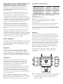
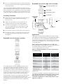
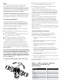
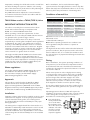
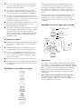
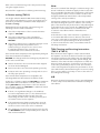
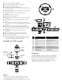
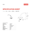
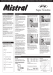
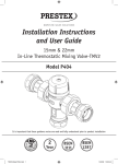
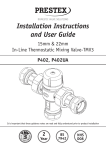
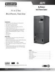
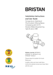
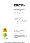
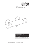
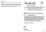
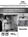
Installation Instructions & User Guide
THERMOSTATIC MIXING VALVE
TX402, TX402UA and TX402UAX
TX402 When used as a TMV3 (TYPE3) valve:
IMPORTANT INTRODUCTION NOTES
The valves covered by these instructions have been
tested and certified as being in compliance with
BS 7942:2000 and NHS Estates Model Engineering
Specification D 08.
Valves operating outside the requirements of these
standards are not covered by the TMV3 Scheme and
are not guaranteed to operate as Type 3 valves.
The installer should be aware of his duty of care and
responsibility in ensuring that compliance with regulations
is maintained. The valve is not guaranteed to function
correctly to the TMV3 specification unless it is installed
and used in accordance with these instructions.
Regular servicing is essential to ensure continued
safe operation of this thermostatic mixing valve. The
recommended service interval must be based on the
valve response to the in-service cold water failure test
results.
This Pegler Yorkshire Model TX402 in-line thermostatic
mixing valve, available in 15mm and 22mm sizes, is
intended to be fitted into applications where the reliable
control of hot water temperature is necessary to prevent
scalding. In the event of cold water supply failure, the
product will shut off the hot water supply.
Water regulations
The Pegler Yorkshire Model TX402 mixing valve must be
installed in accordance with the regulations of the local
water company and the Water Supply (Water Fittings)
Regulations 1999.
Approvals
This product is certified under the BuildCert TMV3
scheme and has been independently tested by the
recognised test laboratory WRc-NSF and is a Water
Regulations Advisory Scheme (WRAS) approved product
and listed in the Water Fittings and Materials Directory.
Conditions of normal Use
Operating Range
High Pressure
Low Pressure
Maximum Static Pressure
10 Bar*
10 Bar*
Hot & Cold Flow Pressure
1.0 to 5 Bar*
0.2 to 1 Bar
Hot Supply Temperature
52 to 65°C
52 to 65°C
Cold Supply Temperature
5 to 20°C
5 to 20°C
Minimum hot inlet to mixed outlet temperature
differential =10°C
*3 bar with PEX + PB Pipe
Note: Valves operating outside these conditions
can not be guaranteed by the Scheme to operate
as Type 3 valves.
The highest flow rates will be achieved under balanced
pressure conditions, but the pressure at the valve
inlets must be within a ratio of 5:1 under flow conditions
and the size and layout of pipework and fittings must take
this into account.
Fittings
Before installation, the system operating conditions of
inlet pressures, hot water temperature and hot and cold
water flow rates should be determined and confirmed to
be within the expected conditions of normal use.
Valves must operate in either a high pressure setting or a
low pressure setting valves are not capable of operation
with, for instance hot water supply in one pressure range
and cold water supply in the other pressure range. In
these conditions it is necessary to either boost one
pressure or reduce the other so that both supplies are
within a common pressure range.
Correct location of the mixing valve is important to
ensure that it is accessible for commissioning and
servicing.
Installation
Separate isolation valves must be installed on the
hot and cold water inlet supplies. To ensure proper
performance of the thermostatic mixing valve, the
isolating valves should preferably be full bore and
always be fully open during operation.
The mixing valve is supplied with filter elements but it
is advisable to additionally install Y-strainers on the hot
and cold water supplies. The isolating valves and
strainers should be installed as close as practicable to
the location of the mixing valve and should always be in
an accessible location.
Before installation, the hot and cold water supply
systems must be thoroughly flushed to remove any dirt/
debris that may have accumulated. Failure to do so may
adversely affect the performance of the mixing valve.
nThe valve body is clearly marked with ‘C’ for Cold and
a blue indicator and ‘H’ for Hot and a red indicator.
The valve must be correctly connected to the
respective supplies.
nThe use of sealing compounds must be avoided since they may intrude into the water supply and impair the
valve performance.
Exploded view of UA angle valve assembly
PRESSURE TAKE OFF PLUG
The Pegler Yorkshire Model TX402 thermostatic mixing
valve is supplied with the tail pieces, inlet filter screen and
main body gasket seals separately located in the packing
box. Each tail piece comprises: a housing with union nut
and an internally fitted, WRAS approved non-return valve.
Assembly Procedure
nUnpack the main valve assembly and check that the bores are free of debris and the end sealing faces are clean.
HEADWORK
HEADWORK ‘O’ RING
FILTER MESH
HANDLE FOR
ISOLATING
VALVE
SEAL
nUnpack the two tailpieces and confirm they are complete with union nuts and sealing gaskets.
nLocate the sealing gaskets, insert them into the union nuts against the faces of the tailpieces and screw the union nuts onto the valve until a tight seal has been made.
UNION NUT
ISOLATING
VALVE
nThe inlet filter screens are pre-fitted in the tail pieces.
nAssemble the valve to the pipework and ensure the hot and cold water pipes have full penetration into
the tailpiece.
Application
The Pegler Yorkshire Model TX402 thermostatic mixing
Exploded view of tail pipe assembly
valve has been independently tested by WRc-NSF against
the requirements of BS 7942:2000 and NHS D08 and
certified as complying with the requirements of the TMV3
Scheme and is suitable for use in the designations shown
in the table below.
Valves approved for designation for use ‘HP’ only:If a water supply is fed by gravity then the supply pressure
should be verified to ensure the conditions
of use are appropriate for the valve.
Table 2 – Required maximum set outlet temperatures
at commissioning.
Designation
Maximum Set
Mixed Water
Temperature
Bibet
HP-B
LP-B
38°C
Shower
HP-S
LP-S
41°C
Washbasin
HP-W
LP-W
41°C
Bath*
HP-T44
LP-T44
44°C
Bath* (Assisted)
HP-T46
HP-T46
46°C
Application
The Pegler Model Yorkshire TX402UA mixing valve is
optionally provided with angled assemblies in lieu of
the tailpiece arrangement shown above. This allows
the connections of the hot and cold water supplies to
be parallel to the mixed water outlet for ease of piping
layouts. The angled valve assemblies incorporate nonreturn valves, filters, isolation valves and test points.
The assemblies comprise an integral full bore ball valve
and in-line strainer in an angled housing. When this
arrangement is used, the requirements for isolation valves
and Y-strainers previously mentioned are regarded as
fulfilled.
*22mm only
The range of available temperature adjustment is 35°C to
48°C But the mixed water temperature at the terminal
fitting should never be set to a temperature that
exceeds the maximum set outlet temperature for the
application (Table 2).
Note:
46°C is the maximum recommended mixed water
temperature from the bath tap. The maximum
temperature takes account of the allowable temperature
tolerances inherent in thermostatic mixing valves and
temperature losses in metal baths. 46°C is not a safe
bathing temperature for adults or children.
The British Burns Association recommends 37°C to
37.5°C as a comfortable bathing temperature for children.
In premises covered by the Care Standards Act 2000,
the maximum mixed water outlet temperature is 43°C.
Commissioning (TMV 3)
The valve must be commissioned under normal
site system conditions and after establishing supply
conditions with the hot and cold water supplies open,
leave the system running to allow temperatures and
pressures to stabilise and be checked.
Prior to commencing commissioning, the following
checks should be carried out.
n The designation of the thermostatic mixing valve matches the application.
n The supply pressures and temperatures are within the operating range of the valve.
n Isolating valves and strainers are provided.
n The supply temperatures are within the range permitted for the valve and by guidance information on the prevention of legionella etc.
If all these conditions are met, proceed to set the
temperature as described below. The Pegler Yorkshire
model TX402 thermostatic mixing valve is supplied
factory set at 43°C but the valve may be simply adjusted
after installation.
The mixed water temperature at the terminal fitting
must never exceed the maximum temperature setting
for the particular application (See Table 2). Note,
It is not possible to install one thermostatic mixing
valve to supply two differing applications unless the
temperature of the higher setting is limited to that of
the lower application.
n Remove the plastic protective cap on top of the valve with the supplied Allen key or other suitable tool.
n Using a close fitting spanner, reduce the mixed outlet temperature by turning clockwise.
n Increase the mixed water outlet temperature by turning counter clockwise.
When the valve has been installed with the correct
conditions of use it is advised that the valve is subjected
to exercise prior to the commissioning at the application
temperature. With hot and cold water flowing through
the valve, operate the valve from full cold to full hot at
least three times.
With the valve at the full cold position bring the valve
to the correct application temperature by turning the
spanner counter clockwise. If the valve overshoots this
temperature, return the valve to the full cold condition,
and reset it to the correct temperature +0-2°C. Do not set
a valve on a lowered temperature as this will not provide
consistent operation.
When the valve is set to the required temperature for the
application carry out 5 cold water isolation tests to further
exercise the valve.
Commissioning Test sequence
After adjust the temperature of the mixed water in
accordance with the valve application (see Table 2)
and the carry out the following sequence:
1.Record the temperature of the hot and cold water supplies.
2.Record the temperature of the mixed water at the largest draw-off flow rate.
3.Record the temperature of the mixed water flow at a smaller draw-off flow rate, which shall be measured.
4.Isolate the cold water supply to the mixing valve and monitor the mixed water temperature recording the maximum temperature achieved and the final
stabilised temperature.
5.Record the equipment, thermometer etc. used for the measurements.
6. After correct commissioning secure the protective cap using the supplied screw.
Note: The final stabilised temperature should not exceed
the values in Table 3.
Table 3 – Guide to maximum stabilised
temperatures recorded during
commissioning
Application
Mixed water temperature
Bidet
40°C
Shower
43°C
Washbasin
43°C
Bath (44°C Fill)
46°C
Bath (46°C Fill)
48°C
In Service Testing (TMV 3)
Frequency of in-service testing
The purpose of in-service testing is to regularly monitor
and record the performance of the
6 to 8 weeks after commissioning carry out the test
sequence detailed above.
thermostatic mixing valve. Deterioration in performance
can indicate the need for service work on the valve and/
or water supplies.
12 to 15 weeks after commissioning carry out the test
sequence detailed above.
Carry out the test sequence detailed below using the
same or equivalent equipment as used for commissioning
the valve.
nCheck the designation of the thermostatic valve matches the application.
nCheck that the supply pressures and temperatures are within the operating range of the valve.
nCheck that the supply temperatures are within the range permitted for the valve and by guidance information on the prevention of legionella etc
nCheck there have been no significant changes in
inlet supply temperatures and pressures since commissioning or the previous in service test.
If significant changes have occurred it is recommended to re-commission the valve.
If the mixed water temperature has changed significantly
from the previous test results (e.g.>1°C), record the
change and before re-adjusting the mixed water
temperature carry out the following checks;
nAll in-line or integral strainers are clean
nAny in-line or integral non-return valves or other anti-backsiphonage devices are in good working order.
nAny isolation valves are fully open.
With an acceptable mixed water temperature complete
the Commissioning test sequence detailed above. If the
final mixed water temperature is greater than the values
in Table 3 and/or the maximum temperature exceeds
the corresponding value from the previous test results
by more than about 2°C the need for service work is
indicated (see TMV servicing and cleaning instructions).
In-service tests should be carried out with a frequency
which identifies a need for service work before an unsafe
water temperature can result.
Depending on the results obtained, the following course
of actions must be followed:
nIf no significant changes (e.g.<1 °C) in mixed
water temperature are recorded between
commissioning and testing at 6 to 8 weeks, or between commissioning and testing at 12 to 15 weeks, the next in-service test can be deferred to 24 to 28 weeks after commissioning.
nIf small changes (e.g.1 to 2 °C) in mixed water temperature are recorded in only one of these
periods, necessitating adjustment of the mixed water temperature, then the next inservice test can be deferred to 24 to 28 weeks after commissioning.
nIf small changes (e.g.1 to 2 °C) in mixed water temperature are recorded in both of these periods,
necessitating adjustment of the mixed water temperature, then the next in-service test
should be carried out at 18 to 21 weeks after commissioning.
nIf significant changes (e.g. >2 °C) in mixed water temperature are recorded in both of these periods, necessitating service work, then the next in-service test should be carried out at 18 to 21
weeks after commissioning. The general principle to
be observed after the first 2 or 3 in-service test is that
the intervals of future tests should be set to those
which previous tests have shown can be achieved
with no more than a small change in mixed water
temperature. It is recommended that In-Service Tests
are carried out once every 6 months as a minimum.
Note:
If there is a residual flow during the commissioning or in
service test during the cold water supply isolation test
then this is acceptable providing the temperature of the
water seeping from the valve is no more than 2°C above
the designated maximum mixed water outlet temperature
setting of the valve as defined in Table 2.
Temperature readings should be taken at the normal flow
rate after allowing the system to stabilise. The sensing
part of the thermometer probe must be fully submerged
in the water that is to be tested.
Before installation, the hot and cold water supply
systems must be thoroughly flushed to remove any dirt/
debris that may have accumulated. Failure to do so may
adversely affect the performance of themixing valve.
Any TMV that has been adjusted or serviced must be
re-commissioned and re-tested in accordance with the
manufacturer’s instructions.
Conditions of normal Use
TX402 When used as a TMV2 (TYPE 2) Valve
IMPORTANT INTRODUCTION NOTES
Operating Range
BS EN 1111
High Pressure
BS EN 1287
Low Pressure
Maximum Static Pressure
10 Bar*
10 Bar*
Hot & Cold Flow Pressure
1.0 to 5 Bar*
0.1 to 1 Bar
The valves covered by these instructions have been
tested and certified as being in compliance with
BS EN 1111:1999 and BS EN 1287:1999.
Hot Supply Temperature
55 to 65°C
55 to 65°C
Cold Supply Temperature
≤ 25°C
≤ 25°C
Valves operating outside the requirements of these
standards are not covered by the TMV2 Scheme and are
not guaranteed to operate as Type 2 valves.
Mixed Water Temperature
Maximum 46°C
Maximum 46°C
The installer should be aware of his duty of care and
responsibility in ensuring that compliance with regulations
is maintained. The valve is not guaranteed to function
correctly to the TMV2 specification unless it is installed
and used in accordance with these instructions. Regular
servicing is essential to ensure continued safe operation
of this thermostatic mixing valve. The recommended
service interval is no greater than 12 months.
This Pegler Yorkshire Model TX402 in-line thermostatic
mixing valve, available in 15mm and 22mm sizes, is
intended to be fitted into applications where the reliable
control of hot water temperature is necessary to prevent
scalding. In the event of cold water supply failure, the
product will shut off the hot water supply.
Water regulations
The Pegler Yorkshire Model TX402 mixing valve must
be installed in accordance with the regulations of
the local water company and the Water Supply
(Water Fittings) Regulations 1999.
Approvals
This product is certified under the BuildCert TMV2
scheme and has been independently tested by an
approved testing laboratory WRc-NSF and is a Water
Regulations Advisory Scheme (WRAS) approved product
and listed in the Water Fittings and Materials Directory.
Installation
Separate isolation valves must be installed on the hot and
cold water inlet supplies. To ensure proper performance
of the thermostatic mixing valve, the isolating valves
should preferably be full bore and always be fully open
during operation.
The mixing valve is supplied with filter elements but it is
advisable to additionally install Y-strainers on the hot and
cold water supplies. The isolating valves and strainers
should be installed as close as practicable to the location
of the mixing valve and should always be in an accessible
location.
Minimum hot inlet to mixed outlet temperature
differential =10°C
*3 bar with PEX + PB Pipe
Note: Valves operating outside these conditions can
not be guaranteed by the Scheme to operate as
Type 2 valves.
The highest flow rates will be achieved under balanced
pressure conditions, but the pressure at the valve inlets
must be within a ratio of 5:1 under flow conditions and
the size and layout of pipework and fittings must take this
into account.
Fitting
Before installation, the system operating conditions of
inlet pressures, hot and cold inlet temperature and hot
and cold water flow rates should be determined and
confirmed to be within the expected conditions of normal
use shown in Table 4.
Valves must operate in either a high pressure setting
or a low pressure setting. These valves are not capable
of operation with, for instance hot water supply in one
pressure range and cold water supply in the other
pressure range. In these conditions it is necessary to
either boost one pressure or reduce the other so that
both supplies are within a common pressure range.
If your water supply cannot meet these conditions then
the valve cannot be guaranteed to operate as a Type 2
valve.
Operating pressures above 5.0 Bar will require the
installation of a pressure reducing valve. Correct location
of the mixing valve is important to ensure that it is
accessible for commissioning and servicing.
nThe valve body is
clearly marked with
‘C’ for Cold and a
blue indicator and
‘H’ for Hot and a red
indicator. The valve
must be correctly
connected to the
espective supplies.
nThe use of sealing compounds must be avoided since they may intrude into the water supply and impair the valve performance.
nThe valve must be so installed that it is readily accessible for commissioning and maintenance when being installed in accordance with TMV2.
The Pegler Yorkshire Model TX402UA mixing valve is
optionally provided with angled assemblies in lieu of
the tailpiece arrangement shown above. This allows
the connections of the hot and cold water supplies to
be parallel to the mixed water outlet for ease of piping
layouts.
nThe valve must be installed with isolation valves on both the hot and cold water systems as close as possible to the valve; so as to allow the valve to be commissioned and tested correctly.
The assemblies comprise an integral full bore ball valve
and in-line strainer in an angled housing. When this
arrangement is used, the requirements for isolation
valves and strainers previously mentioned are regarded
as fulfilled.
nThe valve is supplied with integral strainers on the hot and cold water supplies therefore in-line strainers should not be required.
Exploded view of UA angle valve assembly
nThe valve is fitted with integral “listed” non-return valve cartridges which command the water supply,
therefore the thermostatic valve is protected against cross-flow due to unbalanced line pressures as required by the Water Supply (Water Fittings) Regulations 1999.
PRESSURE TAKE OFF PLUG
HEADWORK
HEADWORK ‘O’ RING
FILTER MESH
Assembly Procedure
nUnpack the main valve assembly and check that the bores are free of debris and the end sealing faces are clean.
HANDLE FOR
ISOLATING
VALVE
SEAL
nUnpack the two tailpieces and confirm they are complete with union nuts and sealing gaskets.
UNION NUT
ISOLATING
VALVE
nLocate the sealing gaskets, insert them into the union nuts against the faces of the tailpieces and screw the union nuts onto the valve until a tight seal has been made.
nInlet filter screens are pre-fitted in the tail pieces.
nAssemble the valve to the pipework and ensure the hot and cold water pipes have full penetration into the tailpiece.
Exploded view of tailpiece assembly
Application
The Pegler Yorkshire Model TX402 thermostatic mixing
valve has been independently tested by WRc-NSF against
the requirements of BS EN 1287 (Low Pressure-LP) and BS
EN 1111 (High Pressure-HP) and certified as complying
with the requirements of the TMV2 Scheme and is
suitable for use in the designations shown in the table
(next page).
Valves approved for designation for use ‘HP’ only:If a water supply is fed by gravity then the supply
pressure should be verified to ensure the conditions of
use are appropriate for the valve.
Table 5 – Recommended set mixed water
outlet temperatures
15mm
22mm
Maximum Set
Mixed Water
Temperature
Shower
HP
HP & LP
41°C
Washbasin
HP
HP & LP
41°C
Bibet
HP
HP & LP
38°C
Bath* (Tub)
HP
HP
44°C
Application
Pressure
The above temperatures are recommended by the
Thermostatic Mixing Valve (manufacturers) Association as
relevant settings for the varying applications shown. This
is the maximum commissioning temperature but valves
may exceed this by 2°C in use.
The range of available temperature adjustment is 35°C
to 48°C but 46°C is the maximum recommended mixed
water temperature from a bath tap. The maximum
temperature takes account of the allowable temperature
tolerances inherent in thermostatic mixing valves and
temperature losses in metal baths. 46°C is not a safe
bathing temperature for adults or children.
The British Burns Association recommends 37°C to
37.5°C as a comfortable bathing temperature for children.
In premises covered by the Care Standards Act 2000, the
maximum mixed water outlet temperature is 43°C.
COMMISSIONING (TMV 2)
The valve must be commissioned under normal
site system conditions and after establishing supply
conditions with the hot and cold water supplies open,
leave the system running to allow temperatures and
pressures to stabilise and be checked.
Prior to commencing commissioning, the following
checks should be carried out.
nThe designation of the thermostatic mixing valve matches the application.
When the valve has been installed with the correct
conditions of use it is advised that the valve is subjected
to exercise prior to the commissioning at the application
temperature. With hot and cold water flowing through
the valve, operate the valve from full cold to full hot at
least three times.
With the valve at the full cold position bring the valve
to the correct application temperature by turning the
spanner counter clockwise. If the valve overshoots this
temperature, return the valve to the full cold condition,
and reset it to the correct temperature +0-2°C. Do not set
a valve on a lowered temperature as this will not provide
consistent operation.
When the valve is set to the required temperature for the
application carry out 5 cold water isolation tests to further
exercise the valve.
nSet the mixed water temperature to the required value. It is advisable to use a calibrated digital thermometer for checking the inlet and outlet temperatures.
nMeasure and record the temperature of the hot and cold water supplies at the inlets to the valve.
nThe supply pressures and temperatures are within the operating range of the valve.
nMeasure and record the temperature of the water discharging from the valve at the greatest draw-off
flow rate.
nIsolating valves and strainers are provided.
If all these conditions are met, proceed to set the temperature as described below.
nIn the absence of other temperatures being specified those detailed in Table 5 are the desired settings.
The Pegler Yorkshire TX402 thermostatic mixing valve
is supplied factory set at 43°C but the valve may be
simply adjusted after installation. The set mixed water
temperature at the terminal fitting must never exceed
46°C
Once the required mixed outlet temperature has been
achieved, isolate the cold water supply and monitor
and record the mixed water temperature including the
maximum and final temperatures achieved. The mixed
water temperature should never exceed 46°C.
nRemove the plastic protective cap on top of
the valve with the supplied Allen key or other
suitable tool.
nUsing a close fitting spanner, reduce the mixed outlet temperature by turning clockwise.
nIncrease the mixed water outlet temperature by turning counter clockwise.
After correct commissioning secure the protective cap
using the supplied screw.
Record all the equipment used during commissioning.
In Service testing (TMV 2)
The Pegler Yorkshire Model P402 thermostatic mixing
valve will provide satisfactory service and a high level of
protection, provided it is maintained and subjected to
In-Service Testing.
Approximately 6-8 weeks after commissioning, the
following tests should be undertaken.
n Check the temperature of the hot and cold water supplies - RECORD
n Check the temperature of the mixed water
temperature at the greatest draw off flow rate – RECORD
n
Check there have been no significant changes in inlet supply temperatures and pressures since
commissioning or the previous in service test.
If significant changes have occurred it is
recommended to re-commission the valve.
If the mixed water temperature has significantly changed
from that measured at installation
RECORD the change and before making any adjustments
to the valve confirm that:n Strainer elements in the hot and cold water supplies are clean and undamaged.
n Non-return valves are clean and operating correctly.
n Isolation valves are operating correctly and are set in the fully open position.
If the mixed water temperature is acceptable, the
following additional observations should be made:Isolate the cold water supply and RECORD the maximum
temperature achieved. After 5 seconds, if water is still
flowing RECORD the temperature of the flow. Restore
the cold water supply and RECORD the stabilised mixed
water outlet temperature.
n
If there is no significant change to the stabilised set outlet temperature (±2°C or less deviation from the original setting) and the fail safe shut-off is functioning, then the valve is working correctly and no further service work is required.
n If the maximum mixed water temperature exceeds the previous test results by more than 2°C then the
need for service work on the valve is indicated.
n The equipment used in these In-Service Tests should be RECORDED and should preferably be the same as that used at installation.
Note:
If there is a residual flow during the commissioning or the
annual verification (cold water supply isolation test) then
this is acceptable providing the temperature of the water
seeping from the valve is no more than 2°C above the
designated maximum mixed water outlet temperature
setting of the valve (See Table 5).
Temperature readings should be taken at the normal flow
rate after allowing the system to stabilise. The sensing
part of the thermometer probe must be fully submerged
in the water that is to be tested. Any TMV that has been
adjusted or serviced must be re-commissioned and
re-tested in accordance with the manufacturer’s
instructions.
In the absence of any other instruction or guidance, it
is recommended that In-Service Tests are carried out
once every 12 months as a minimum. If the temperature
is outside of the expected range it will be necessary
to remove and clean the valve in accordance with the
following instructions.
TMV Cleaning and Servicing Instructions
(TMV 2 & TMV 3)
Most domestic water supplies contain calcium which
will separate out when the water is heated in a system.
The degree and speed of scaling may vary depending
on factors such as water flow rates, system design, the
hardness of the water and the temperature to which the
water is heated. Deposits of scale may over time form
in the valve, particularly at the hot inlet. The formation
of the scale may adversely affect the performance of the
valve which will be detected during the in-service testing.
If this occurs it will be necessary to remove the valve for
de-scaling and servicing.
N.B.
Excessive chemical dosing may result in internal damage
to valve components and remove lubrication leading to
valve failure.
n Isolate the hot and cold supply.
n Remove the valve to a clean working area.
n Remove the protective cap.
n Unscrew the headwork of the valve.
n Carefully remove the element and valve assembly and put to one side.
n Remove the main spring and flow guide and carefully put to one side.
n Inspect the components for contamination or damage.
n Clean or replace as necessary.
n Remove the two ‘0’ rings.
n Clean the valve body and headwork using a propriety de-scaler.
n Thoroughly rinse the body and headwork in clean water.
n Carefully fit new o rings from the service kit taking care to ensure they are not damaged and are correctly
located.
n Lubricate the o rings with the lubricant provided.
n Re-fit the flow guide and spring lubricating the flow guide around the greatest diameter with the lubricant provided.
n Lubricate the shuttle valve with the lubricant provided.
n Re-fit the shuttle valve and element assembly.
n Re-fit the headwork ensuring correct tightening.
n Re-fit the valve assembly.
n If after cleaning the valve, and replacing the ‘0’ ring seals, the valve does not function correctly, it may be necessary to replace the thermal element.
A
A
B
C
D
D
E
Spare Part Order Code
A
854864
Purple TMV3 Protective cap
complete with screw
B
854447
Hexagon key
C
854454
Service kit
D
854869 (15mm)
854870 (22mm)
Tail Piece Strainer kit
E
854456 (15mm)
854457 (22mm)
Sealing washer
Sealing washer
Exploded view of TMV assembly
HEADWORK
PROTECTIVE
CAP AND
FIXING SCREW
ELEMENT
AND VALVE
ASSEMBLY
Description
TX402UAX
MAIN SPRING
AND FLOW
GUIDE
Spares
In order to ensure that the Model TX402 thermostatic
mixing valve continues to provide satisfactory service,
only GENUINE Pegler Yorkshire spare parts must be used.
The TX402UAX is an approved variant of the TX402UA,
providing an additional outlet on the angle valve. This
allows for a connection to ‘cold water outlets’ without
affecting the inlet supply to the mixing valve. The
connection can be blanked to enable the valve to be
used in the two inlet, one outlet mode.
Tectite Installation Instructions
Demounting
Always cut the tube square, using a rotary tube cutter
whenever possible. Ensure the cutter wheel is appropriate
for the material being cut.
Place the forks of the disconnecting tool around the
fitting assembly. The fork side carrying the Tectite brand
logo should be positioned around the tube/pipe with the
opposite side around the neck of the fitting.
If you are using PEX or PB pipe cut the pipe using pipe
shears.
Deburr the tube end, both internally and externally to
create a 1mm chamfer on the outside of the tube.
Squeeze the disconnecting tool with one hand until the
release collar in the fitting is compressed. With the other
hand, twist out the tube/pipe using the thumb as a lever
against the tool to assist disconnection.
Check the fitting and tube/pipe for damage before
remaking the joint.
The plastic disconnecting clip may be used where only an
occasional disconnecting facility is needed.
Check the tube ends are free from damage and clean,
wiping away any swarf to avoid damaging the ‘0’ ring on
tube insertion. Tube end must also be free from stickers,
tape and adhesive residues.
Where using PEX or PB you must use always insert a
support liner ensuring it is the correct liner as specified
by the pipe manufacturer. If the pipe has been used
on previous installations you will need to cut it back to
behind the teeth or score marks.
Mark the socket depth with a marker.
Fitting socket depths for Tectite:
Size
Classic, PRO & 316
15mm
23mm
22mm
27mm
For chrome plated copper tube you must scribe the tube
using the correct Tectite Scribing tool.
Select the correct type and size of fitting for pipework.
The fitting should be kept in its bag until point of use to
protect the ‘0’ ring.
Check the fitting ensuring the grab rings/’O’rings have
not been contaminated with grit or debris.
Remove any protective caps fitted to the socket.
Insert the tube/pipe firmly with a slight twisting action
until it reaches the tube stop with a positive “click”.
Ensure the depth insertion mark corresponds with the
mouth of the fitting, then pull firmly on the tube/pipe to
ensure the fitting is secure.
UK Sales
Brochure Hotline
Export
Pegler Yorkshire Group Limited
St. Catherine’s Avenue, Doncaster,
South Yorkshire, DN4 8DF, England.
Tel: 0844 243 4400 Fax: 0844 243 9870
Free Phone: 0800 156 0010
Free Fax: 0808 156 1011
Email: [email protected]
Tel: +44 (0) 1302 855 656
Fax: +44 (0) 1302 730 513
Email: [email protected]
Technical Help
Follow us on:
Free Phone: 0800 156 0050
Free Fax: 0808 156 1012
Email: [email protected]
www.pegleryorkshire.co.uk
Free Phone: 0800 156 0020
Free Fax: 0808 156 1011
Email: [email protected]
All brand names and logo styles are registered
trademarks. Maintaining a policy of continual
product development, Pegler Yorkshire reserves the
right to change specifications, design and materials
of products listed in this leaflet without prior notice.