1
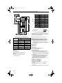
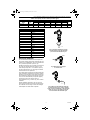
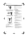
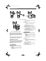
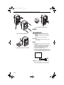
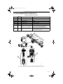
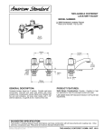
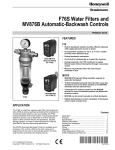
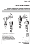
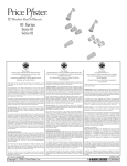
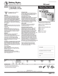
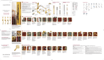
62-0165.fm Page 1 Wednesday, June 20, 2007 9:21 AM
Braukmann
F74C Reverse Rinsing Filter;
MV876 Automatic-Backwash Controls
INSTALLATION INSTRUCTIONS
SPECIFICATIONS
MV876B1018
(Bayonet fitting
for F74C)
F74C
APPLICATION
‘The F74C Reverse Rinsing Water Filters, used at
point-of-entry (POE) to remove sediment and debris from
residential or commercial water systems, ensure a
continuous supply of filtered water. The fine filter
prevents the ingress of foreign bodies, such as rust
particles and grains of sand. The flow, filtering capacity
and ease of cleaning make the F74C the ideal filter for
the most demanding applications. Both horizontal and
vertical installations are possible.
The MV876 Automatic-Backwash Control is available as
an accessory. This control is fitted to the drain valve and
is programmed by the user to automatically perform the
backwash function according to the desired interval.
IMPORTANT
The specifications given in this publication do
not include normal manufacturing tolerances.
Therefore, units may not exactly match the
listed specifications. Also, products are tested
and calibrated under closely controlled
conditions, and some minor differences in
performance can be expected if those
conditions are changed.
F74C:
Models:
Water filters with 100 micron screens and hose
connections.
F74C1015: 3/4 in. sweat and NPT threaded tailpieces.
F74C1023: 1 in. sweat and NPT threaded tailpieces.
Materials of Construction:
Body: Engineered plastic.
Inlet/Outlet Adapter: Bronze.
Sump: Engineered plastic.
Screen: Stainless steel.
Internal Construction: Acetal copolymer.
Seals: NBR.
Ball Valve: Brass with PTFE seals.
Inlet Pressure:
Minimum: 22 psi (with unrestricted backwash discharge).
Maximum: 232 psi.
Medium: Water.
Maximum Operating Temperature: 86°F (30°C).
Pipe Size: 3/4 in. and 1 in.
Mounting Position: For vertical or horizontal
(filter bowl always downwards).
Dimensions: See Fig. 1 and Table 1.
® U.S. Registered Trademark
Copyright © 2001 Honeywell • All Rights Reserved
62- 0165
62-0165.fm Page 2 Wednesday, June 20, 2007 9:21 AM
F74C REVERSE RINSING FILTER; MV876 AUTOMATIC-BACKWASH CONTROLS
80.0
70.0
L
60.0
FLOW (GPM)
l
50.0
40.0
30.0
h
20.0
H
10.0
0.0
0
3
7
10
20
PRESSURE DROP (PSI)
MAXIMUM RECOMMENDED
PRESSURE DROP WITH
CLEAN SCREEN.
T
M18087
Fig. 1. Dimension drawing of F74C.
Table 1. Dimensions of F74C in in. (mm).
Connection Size
Dimension
3/4
1
H
12-13/16 (324)
12-13/16 (324)
h
11-3/16 (285)
11-3/16 (285)
L
6-3/8 (162)
7-1/4 (184)
l
3-9/16 (90)
3-15/16 (100)
D
4-1/8 (105)
4-1/8 (105)
r
1-1/16 (27)
1-1/16 (27)
t
2-5/8 (66)
2-5/8 (66)
T
5-5/16 (150)
5-5/16 (150)
Weight:
3/4 in.: 6 lb (2.7 kg).
1 in.: 7 lb (3.2 kg).
Operating Pressure Drop Versus Flow:
See Fig. 2.
Maximum recommended: 3 psi to 7 psi
(with clean screen).
62-0165
M17656
Fig. 2. F74C Pressure drop vs. flow.
D
r
F74C1015
F74C1023
Connections: Union on inlet and outlet: External NPT
threaded or sweat. Inlet/outlet assembly can be rotated
to fit on vertical or horizontal piping.
Screen Sizes: Shipped with Device: 100 microns.
MV876 Automatic-Backwash Control:
MV876B1018: Bayonet mounted shaft of 24 Vac motor
and timer replaces ball valve manual control for
automatic backwash at preprogrammed intervals.
24V transformer not included. For use with F74C and
F76S Filters only.
Specifications:
Power: 4 VA.
Current: 170 mA.
Voltage: 24 Vac.
Cycle time: 20 seconds (approximate).
Timer: Variable. See Table 3.
Accessories for F74C:
AF74-1A Replacement filter assembly for F74C, 3/4 in.
and 1 in., 100 micron; includes the filter insert
complete (O-ring, mesh with mesh support, impeller),
sump O-ring (mounted between the filter housing and
the sump).
KF74-1A Replacement sump assembly for the F74C;
includes the sump assembly complete (ball valve,
plastic air gap adaptor), sump O-ring (mounted
between the filter housing and the sump).
TBD Opaque sump cover for F74C 3/4 in. and 1 in.
U76S5015 3/4 in. sweat tailpiece.
U76S5023 1 in. sweat tailpiece.
U76T1014 3/4 in. NPT tailpiece.
U76T1022 1 in. NPT tailpiece.
901444 Union gasket for F74; 3/4 in., 10 gaskets in
package.
901445 Union gasket for F74; 1 in., 10 gaskets in
package.
ZR 10 K-34 Double ring wrench for removing filter bowl.
2
62-0165.fm Page 3 Wednesday, June 20, 2007 9:21 AM
F74C REVERSE RINSING FILTER; MV876 AUTOMATIC-BACKWASH CONTROLS
Table 2. Flow Capacity of F74C in Gallons per Minute (gpm).
Pressure Drop in psi
Model
Size
1
2
3
4
5
15
Cv
F74C1015
3/4
9.0
12.7
15.6
18.0
20.1
34.9
9
F74C1023
1
10.1
14.3
17.5
20.2
22.6
39.1
10.1
Table 3. MV876B Timer Selections.
Program Value
Backwash Interval
1
4 minutes
2
8 minutes
3
16 minutes
4
32 minutes
5
1 hour
6
2 hours
7
4 hours
8
8 hours
9
17 hours
10
34 hours
11
3 days
12
6 days
13
11 days
14
23 days
15
45 days
16
3 months
M17705
Fig. 3. Ideal F74C installation. A funnel
mounted directly under the backwash
port is the best installation layout.
Planning the Installation
The F74C should be sized based on the required flow
rate and the resulting pressure drop across the filter. As a
guideline for most applications, the F74C should be sized
for a pressure drop between 3 psi and 7 psi.
M17706
EXAMPLE: What size F74C is required to provide a flow
rate of 20 gpm? Reading Table 2 at 20 gpm, a 3/4 in.
model has 5 psi drop and a 1 in. model has 4 psi drop.
As both models meet the 3 to 7 psi range, the selection
should be based on size preference.
Fig. 4. Make sure the inlet pipe
is not downsized.
An increased pressure drop across the filter results when
higher velocities are maintained to increase the capacity
through any given size filter. Severe pressure drops will
be encountered as capacity approaches that of the pipe
size. To ensure the backwash cycle operates properly
and cleaning action is not reduced, follow all
recommendations in Fig. 3. Refer to Fig. 3a for an ideal
installation.
All filter installations are different. The size, type and
amount of dirt and debris and the flow rate must always
be considered when choosing a screen and deciding to
install multiple F74C Water Filters in parallel.
M17707
Fig. 5. Make sure the backwash outlet pipe
is not downsized, long or crimped. Instead,
install a short oversized pipe on the backwash
outlet. Do not use a low capacity solenoid
valve to automate the backwash cycle.
3
62-0165
62-0165.fm Page 4 Wednesday, June 20, 2007 9:21 AM
F74C REVERSE RINSING FILTER; MV876 AUTOMATIC-BACKWASH CONTROLS
Check ratings given in these instructions and on the
product to make sure the product is suitable for your
application.
Make sure the installer is a trained, experienced service
technician.
Use these instructions to check out product operation
after installation.
M17708
CAUTION
Fig. 6. Make sure the backwash outlet is not raised
above the F74C. If the backwash outlet must be
raised above the F74C, increase the inlet pressure
5 psi for every 10 feet that it is raised.
Equipment Damage Hazard.
Excessive pressure or temperature can
damage the device.
Make sure water temperature and pressure are
below maximum ratings specified.
CAUTION
Equipment Damage Hazard.
Excessive heat can damage internal parts.
Before sweat soldering, separate the tailpieces
and nuts from the inlet/outlet adapter.
M17709
Fig. 7. Make sure the F74C is not used with
an undersized pump. An undersized pump
may not provide proper pressure or flow.
F74C Installation.
When installing an F74C, use the following procedure:
1.
2.
3.
Shut off water supply by closing the water supply
valve.
Install inlet/outlet adapter so that filter is vertical.
Install the F74C in the water line with the arrow
pointing in the direction of water flow.
IMPORTANT
When using an MV876, stop here and install the
MV876.
4.
5.
6.
Open a downstream tap.
Slowly open the water supply valve.
Once the F74C sump fills with water, close the
downstream tap and fully open the water supply
valve.
MV876 Installation
M17704
1. Open the backwash outlet ball valve.
Remove the backwash outlet handle.
2.
3.
Fig. 8. Make sure the F74C is not installed
in a bypass across a pump.
4.
INSTALLATION
5.
6.
7.
When Installing this product...
Read these instructions carefully. Failure to follow them
could damage the product or cause a hazardous
condition.
62-0165
8.
4
Install the MV876. See Fig. 9 and 10.
When you rotate the MV876 on installation, it
closes the backwash outlet ball valve.
Connect the MV876 to a 24 Vac power supply.
See fig. 14.
Open a downstream tap.
Slowly open the water supply valve.
Once the F74C sump fills with water, close the
downstream tap and fully open the water supply
valve.
Program the desired backwash interval by pushing
the program button until the desired interval
number appears in the display.
62-0165.fm Page 5 Wednesday, June 20, 2007 9:21 AM
F74C REVERSE RINSING FILTER; MV876 AUTOMATIC-BACKWASH CONTROLS
MV876B
M16481
Fig. 9. Installing the MV876.
1.
Unscrew the four housing screws and set them
aside. See Figure 11.
IMPORTANT
Make sure the connecting cable is protected
from damage when the MV876 cover is
removed.
76B
MV8
M16483
2.
3.
4.
5.
6.
Remove the MV876 cover. See Fig. 11.
Insert four AA alkaline batteries. See Fig. 12.
Replace the cover.
Replace and tighten the four housing screws.
To avoid unnecessary battery drainage, connect
the MV876 to power as soon as possible after
inserting new batteries.
7. To ensure the availability of battery power, replace
the batteries after a power loss.
If the 800 mA fuse blows, replace it as follows:
Fig. 10. Final position of MV876 and F74C.
WARNING
As the F74C operates, screens become plugged.
Backwash the F74C when the pressure gauge measures
about five psi lower than when first installed. However,
each installation is different. Residential applications can
require backwash only once a week, or once every few
weeks.
Electrical Shock or Equipment Damage
Hazard.
Can shock individuals or short equipment
circuitry.
Disconnect power supply before installing the
batteries or fuses.
For residential applications, backwashing the F74C once
a week, regardless of need, is an excellent guideline to
follow to ensure F74C peak operating efficiency.
Fitting Batteries and Fuses
The batteries (not included) provide power to the MV876
in the event of a power loss. This is desirable, especially
when power loss occurs during the reverse rinsing cycle.
to provide this, the MV876 requires four AA alkaline
batteries. Install these batteries in the cover of the
MV876 as follows:
1.
Unscrew the four housing screws and set them
aside (see Fig. 11).
IMPORTANT
make sure that the connecting cable is
protected from damage while the MV876 cover
is removed.
2.
3.
4.
5.
6.
7.
WARNING
Remove the MV876 cover.
Remove and discard the old fuse (see Fig. 13).
Insert a new 800 mA fuse.
Replace the cover.
Replace and tighten the four housing screws.
Reconnect the power supply.
Electrical Shock or Equipment Damage
Hazard.
Can shock individuals or short equipment
circuitry.
Disconnect power supply before installing the
batteries or fuses.
5
62-0165
62-0165.fm Page 6 Wednesday, June 20, 2007 9:21 AM
F74C REVERSE RINSING FILTER; MV876 AUTOMATIC-BACKWASH CONTROLS
M17351
76B
MV8
Fig. 13. Replacing the MV876 fuse.
WIRING
WARNING
M17352
Fig. 11. Removing the MV876 cover.
Electrical Shock or Equipment Damage
Hazard.
Can shock individuals or short equipment
circuitry.
Disconnect power supply before wiring.
IMPORTANT
All wiring must comply with applicable codes
and ordinances.
MV876
76B
MV8
1.
Mount the 24 Vac transformer and wire as shown
in Fig. 14.
Reconnect power to the system. When the system
is powered, the MV876 will run through one
backwash cycle (approximately 20 seconds).
Set MV876 backwash interval to the desired
setting. See the Operation section.
Check MV876 operation by interrupting primary
power to the transformer. When power is switched
back on, the MV876 will backwash the F74C once.
2.
M17353
3.
Fig. 12. Installing batteries in the MV876.
4.
MV876
1
L1
(HOT)
L2
1
POWER SUPPLY. PROVIDE DISCONNECT MEANS AND OVERLOAD
PROTECTION AS REQUIRED.
M16484
Fig. 14. Wiring diagram for F74C with MV876.
62-0165
6
62-0165.fm Page 7 Wednesday, June 20, 2007 9:21 AM
F74C REVERSE RINSING FILTER; MV876 AUTOMATIC-BACKWASH CONTROLS
F74C REPLACEMENT PARTS LIST (SEE FIG. 15).
Table 4. Parts and Accessories for F74C.
Letter in
Part Number Fig. 15
Description
Contents
U76S5051
A
3/4 in. sweat tailpiece
Tailpiece
U76S5023
A
1 in. sweat tailpiece
Tailpiece
U76T1014
B
3/4 in. NPT tailpiece
Tailpiece
U76T1022
B
1 in. NPT tailpiece
Tailpiece
901444
C
Union gasket, 3/4 in.
10 gaskets in package
901445
C
Union gasket, 1 in.
10 gaskets in package
AF74-1A
D
Replacement filter assembly for
Includes the filter insert complete (O-ring, mesh with
F74C, 3/4 in. and 1 in., 100 micron. mesh support, impeller), sump O-ring (mounted
between the filter housing and the sump).
KF74-1A
E
Replacement sump assembly for
F74C
Includes the sump assembly complete (ball valve,
plastic air gap adaptor), sump O-ring (mounted between
the filter housing and the sump).
A
B
C
C
B
A
E
D
M18212
Fig. 15. F74C Exploded View. parts are keyed to F74C Replacement parts List.
7
62-0165
62-0165.fm Page 8 Wednesday, June 20, 2007 9:21 AM
Home and Building Control Home and Building Control
Honeywell
1985 Douglas Drive North
Golden Valley, MN 55422
62-0165 G.R. 3-01
Honeywell Limited-Honeywell Limitée
35 Dynamic Drive
Scarborough, Ontario
M1V 4Z9
Printed in U.S.A. on recycled
paper containing at least 10%
post-consumer paper fibers.
www.honeywell.com