1
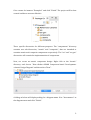
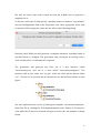
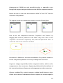
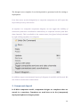
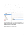
User Guide: Design atomic and composite components 1. Atomic component design In X-‐MAN, components can be atomic and composite. In this tutorial, we will design an atomic component. Start X-‐MAN, and create a new project by selecting “File-‐>New Project-‐>Other-‐ >XMAN Component-‐based Development-‐>X-‐MAN Project”. A dialog box (as shown below) will display to let you set the name of the project. 1 Give a name for instance “Example1” and click “Finish”. The project will be then created and has a structure like this. There specific directories for different purposes. The “components” directory contains two sub-‐directories, “atomic” and “composite”, that are intended to contains atomic and composite components respectively. The “src” and “src-‐gen” directories will contain the implementation of components. Now, we create an atomic component design. Right click at the “atomic” directory and choose “New-‐>Other-‐>XMAN Component-‐based Development-‐ >Atomic Design Diagram” and then select “Next”. A dialog as below will display asking for a diagram name. Give “Incrementor” as the diagram name and click “Finish”. 2 A file called “Incrementor.diagram” will be created under “atomic” directory and it will also be opened. The circle CU represent the computation unit of the under construction atomic component. It contains the implementation of the component. 3 The design palette (see Fig. 1a) now shows “Service”, “Input”, “Output”, and “Data Element”, just as it should. Fig. 1a: Atomic component design palette In X-‐MAN component model, an atomic component is constructed from an invocation connector connecting to a computation unit. Computation unit provide the implemented business logic of a component. In addition, a component has an interface that consists of services and data elements. Now we need to specify what services this atomic component will have. Select “Service” from palette and click somewhere in the diagram to create a service. We should now see a rounded rectangle representing a service. Provide a name for this service for instance “increment”. 4 We can change this value at any time later by clicking on the name or using the “Properties” view. The red marker in the X-‐MAN tool indicates a marked element invalid. We can see more details by check the “Problems” view. For our service, it is not yet valid because a service should have at least an input or output. We now create one input and one output using the palette. Name the input “m” and the output “n”. As inputs and outputs are data, they need to be associated with specific types. Let’s use “Integer” for both. Also for an atomic component’s services, inputs and outputs must be ordered, starting from 0. Using the “Properties” view, we can do this. Click on the input, choose “Integer” for DataType and “0” for Order as in the figure below. Repeat this for the output. The component now needs to be implemented. This effectively means we will implement the service “increment”. Right now, the X-‐MAN tool only supports Java as implementation but it will be extended to support C/C++ later. 5 We will not write code from scratch but ask the X-‐MAN tool to generate a template for us. To do this, select the CU and specify a package name for instance “org.example” into the PackageName field in the Properties view. After typing this value, click on another field to apply the value and we will see the following dialog. Basically, the X-‐MAN tool will generate a template whenever a package name is specified anew or changed. The generation may overwrite an existing source code and therefore a confirmation is required. The generation will generate two files, one is a Java interface called “Incrementor.java” and one is a class called “IncrementorImpl.java”. The interface will be put under the “src-‐gen” while the class will be placed under “src”. Choose Yes to proceed and we should now see these files as shown in next figure. We now implement the service by editing the template “IncrementorImpl.java”. Open this file by clicking the “Edit implementation code” button in “Properties” view while the CU must be selected and type in some code. An example is shown below. 6 After editing the source code, save and close the file. The source code will be automatically assigned to the CU of the component. We could see this and make change later through the “Properties” view and the button “Edit implementation code”. If we make a change to an existing service i.e. adding/renaming more inputs or outputs, or adding/dropping services, we will have to make necessary changes to the implementation. We will update the templates by choosing the menu “X-‐MAN-‐ >Generate Code”. The interface will be overwritten to reflect the changes. The class 7 will not be overwritten so that our previous implementation will be intact. We will have to manually update the class file to match the new interface. The atomic component is now fully designed. The component can be stored in the repository. For instructions on how to deposit a component, go to Section Deposit a component. 2. Composite component design In order to design a composite component, we need two or more components and composition connectors. We will design a simple composite component that uses both basic composition connectors known as Sequencer and Selector. Note that the composite component we are going to design is totally made up to serve the purpose of an example. We do not need to worry about the soundness and usefulness of the design. We create a fresh composite component diagram by right clicking the “composite” directory and choose “New-‐>Other-‐>XMAN Component-‐based Development-‐>Composite Component Diagram” and then select “Next”. We then provide a name for this composite component diagram, for instance Foo. This composite component will need three component instances from two component designs in the repository, which are “Incrementor” and “IntAdder”. 8 The former one was design in the previous section. The latter one is provided here. We may need to deposit them in repository if they are not there yet. To create a component instance, select a component, for example “Incrementor”, from the “Repository Explorer”, right-‐click on it and choose “Retrieve/Deploy” or go to “X-‐MAN-‐>Retrieve” menu. A dialog will appear as in figure below. We need to supply a name for this instance and select at least a service this instance will contain (from possibly a few designed services). So, let’s use “inc” for the name and tick the service “increment”. You only need to select/deselect a service and its inputs and outputs will be automatically selected/deselected. 9 Components in X-‐MAN have only provided services, as opposed to ones having both required and provided services in ADL like component models. Repeat this step to create two more instances called “ia1” and “ia2” from the component “IntegerAdder”. The diagram should now contain three instances as in the following figure. Now, we use two composition connectors, “Sequencer” and “Selector” by dragging them from the palette. Give the names “SEQ1” and “SEL1” to the “Sequencer” and “Selector” respectively. Also, name the input inside “SEL1” as “cond”. We now see the connectors as follows. Connectors in X-‐MAN are execution coordinators. They initiate control to invoke components (and their services) or subsequent connectors. Sequencer simply sequentially invokes composed entities, which can be components or other connectors. Sequencing is dictated in the attribute of the connections between Sequencer and components or other connectors. Selector, working like a switch structure without break between cases, selects one or more of its branches. Selector requires one or more input. In 10 order to activate a branch, Selector tests the conditional expression associated with the branch with the values of Selector’s inputs. To compose components by a connector, we have to connect the connector to the components. We will use the connection tool in the palette to do this. Select “CoordinationConnection” , click on a connector and then click on a component or another connector. While the connection tool is active, we can perform many connections without reselecting the tool after every connection is made. Select the “Select” tool after all connections are done. We can also bend connections to make the diagram clear and neat. To do this, select a connection and drag its anchor points (yellow circles on the connection itself). We now connect “SEL1” with two components “ia1” and “ia2” created previously. We then connect “SEQ” with “inc” and “SEL1”. Sequencer needs a specific sequence for all its branches. Select the branch connected with “inc” and set the property “Condition” to 0 using the “Properties” view of course. Repeat this step for the branch connected to “SEL1” with value 1. This means the sequence of activation/invocation will be “inc” followed by “SEL1”. Selector requires conditional expressions on its branches. Hence, select the connection to “ia1” and set the property “Condition” as “cond < 1000”. Set the “Condition” on the second branch as “cond >= 1000”. This means that “ia1” will be activated and invoked if the value of “cond” is less than 1000. Otherwise, “ia2” will be activated. The diagram should now look like in the following figure. 11 A composite component, like an atomic component, provides services. A composite component’s service is one that is realised by coordinating services of sub-‐components. We create a service using the service tool from the palette and name it “S1”. Create three inputs, “i1” “i2” and “i3”, and one output “o1”. Set the order attribute, starting from 0, so that the order of inputs is “i1”, “i2” and “i3”. Repeat this for the output “o1”. Now, we need to specify how values of these inputs and outputs are routed to corresponding inputs and outputs of component instances. To do this, we use data channels. To create a data channel, select the “DataChannel” tool from the palette and connect a pair of input and output. Similarly to other connection tool, we can do not need to reselect the tool after every connection made. We connect the inputs and outputs in the diagram as in the following figure. 12 As mentioned above, a service of composite component is realized by sub-‐ components’ services. We now need to do this by using the “ServiceReference” tool in the palette. The service “S1” is realised by three services from the three instances. We will create three references inside the service “S1”. For every reference, we need to assign it to a specific service in a sub-‐component. We do this by selecting a reference and choose a service from the combo box “Referenced Service” in the “Properties” view. For instance, service “increment” of the instance “inc” by selecting “inc.increment”. When complete, the service “S1” will look like this. 13 The design is now complete. It can be deposited or generated code for testing or deployment. If we have more services designed for a composite component, we will repeat the steps above for every new service. At anytime in a composite component diagram, we can toggle the visibility of connectors (and their coordination connections) or composite services (and their data channels). This is available in the context menu (see figure below) activated by right clicking anywhere in a diagram. In addition, support on automatic layout of a diagram is available via Zest tool. We can choose it in the same context menu. 3. Component deposit In X-‐MAN component model, component designs are templates that are stored in a repository. Templates are used later on in the (component) deployment phase to design systems. 14 To deposit a component, e.g. Incrementor, we have two ways. One way is to use “drag-‐n-‐drop” facility and another way is through the X-‐MAN menu. To use “drag-‐n-‐drop”, we first need to make sure the “Repository Explorer” view visible. If we do not see this view, we can open it by selecting “Window-‐>Show View-‐>Other-‐>X-‐MAN-‐>Repository Explorer”. We then drag the “Incrementor.atomic” file to the “Repository Explorer” view and drop it onto a suitable category for instance “Example” as in the figure below. Note that the diagram does NOT have to be opened in this way. To use the X-‐MAN menu, we first have to open the “Incrementor.diagram” and secondly select the menu “X-‐MAN-‐>Deposit”. Note that we do NOT have to have the “Repository Explorer” view visible in this way. A dialog will display to ask for some further details. 15 Provide these as for instance in the above figure press OK to go ahead. If the deposit is successful, we will see it under the selected category when inspecting the repository through the “Repository Explorer” view. If it is not successful, an error dialog will appear. 16