1
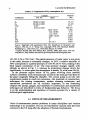
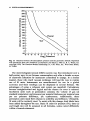
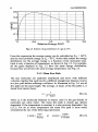
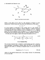
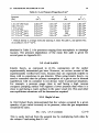
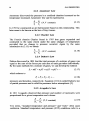
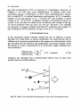
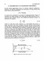
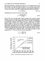
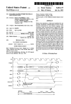
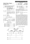
A User's Guide to
Vacuum Technology
Third Edition
John F. O'Hanlon
Professor Emeritus of Electrical and Computer Engineering
The University of Arizona
A JOHN WILEY & SONS, INC., PUBLICATION
This Page Intentionally Left Blank
A User's Guide to
Vacuum Technology
Third Edition
This Page Intentionally Left Blank
A User's Guide to
Vacuum Technology
Third Edition
John F. O'Hanlon
Professor Emeritus of Electrical and Computer Engineering
The University of Arizona
A JOHN WILEY & SONS, INC., PUBLICATION
Copyright 0 2003 by John Wiley & Sons, Inc. All rights reserved.
Published by John Wiley & Sons, Inc., Hoboken, New Jersey.
Published simultaneously in Canada.
No part of this publication may be reproduced, stored in a retrieval system or transmitted in any form or
by any means, electronic, mechanical, photocopying, recording, scanning or otherwise, except as
permitted under Section 107 or 108 of the 1976 United States Copyright Act, without either the prior
written permission of the Publisher, or authorization through payment of the appropriate per-copy fee to
the Copyright Clearance Center, Inc., 222 Rosewood Drive, Danvers, MA 01923, (978) 750-8400, fax
(978) 750-4470, or on the web at www.copyright.com. Requests to the Publisher for permission should
be addressed to the Permissions Department,John Wiley & Sons, Inc., 111 River Street, Hoboken, NJ
07030, (201) 748-601 1, fax (201) 748-6008, e-mail: [email protected].
Limit of LiabilityiDisclaimerof Warranty: While the publisher and author have used their best efforts in
preparing this book, they make no representation or warranties with respect to the accuracy or
completenessof the contents of this book and specifically disclaim any implied warranties of
merchantabilityor fitness for a particular purpose. No warranty may be created or extended by sales
representatives or written sales materials. The advice and strategies contained herein may not be
suitable for your situation. You should consult with a professional where appropriate. Neither the
publisher nor author shall be liable for any loss of profit or any other commercial damages, including
but not limited to special, incidental, consequential, or other damages.
For general information on our other products and services please contact our Customer Care
Department within the U.S. at 877-762-2974, outside the U.S. at 317-572-3993 or fax 317-572-4002.
Wiley also publishes its books in a variety of electronic formats. Some content that appears in print,
however, may not be available in electronic format.
Library of Congress Cataloging-in-PublicationData:
Library of Congress Cataloging-In-PublicationData is available:
0-471 -27052-0
Printed in the United States of America.
1 0 9 8 7 6 5 4 3 2 1
For Jean, Carol, Paul, and Amanda
This Page Intentionally Left Blank
Preface
This book is intended for the vacuum system user-the university student,
technician, engineer, manager, or scientist-who wishes a fundamental
understanding of modern vacuum technology and a user’s perspective of
modern laboratory and industrial vacuum technology.
Vacuum technology is largely secondary; it forms part of other
technologies that are central to analysis, research, development, and
manufacturing. It is used to provide a process environment. Many
advances in vacuum technique have resulted from the demands of other
technologies, although scientists and engineers have studied vacuum for its
own sake. The average user is process-oriented and becomes immersed in
vacuum technique only when problems develop with a process or when
new equipment purchases become necessary.
A User’s Guide to Vacuum Technology, 3rd Edition focuses on the
operation, understanding, and selection of equipment for processes used in
semiconductor, optics, and related technologies. It emphasizes subjects not
adequately covered elsewhere, while avoiding in-depth treatments of topics
interesting only to the designer or curator. Residual gas analysis is an
important topic whose treatment differs from the usual explanation of mass
filter theory. Components such as the turbomolecular and helium gas
refrigerator cryogenic pumps are now widely used but not well understood.
The discussion of gauges, pumps, and materials is a prelude to the central
discussion of systems. System designs are grouped according to their
function. Current designs are either single-chamber or multichamber; the
details of each design are determined by the requirements of an industrial
or research application.
In this edition, the discussion of gauges, pumps, and materials has been
updated, where relevant, to reflect changes in practice. Spinning rotor
gauges are no longer a laboratory curiosity. Ultrahigh vacuum gauges,
though limited in their availability, will be a necessity in next-generation
production deposition systems. Ultraclean, low dead volume metrology
and valves, along with superior materials and cleaning techniques, have
made contamination-free manufacturing a reality.
Ultraclean vacuum, once the domain of the researcher, is now routinely
used for high-volume production of semiconductor chips and storage
vii
viii
PREFACE
media. However, methodologies for reaching low pressures in a clean
manner have changed significantly. No longer are single-chamber systems
baked for twenty-four hours. Rather, cassette-based loadhnload chambers
serve as high-volume interfaces between atmosphere and ultraclean
process chambers. These chambers, which can be accessed in serial or
random order, are only exposed to atmosphere during maintenance.
Large, efficient multichamber medium and highvacuum systems are
used in high-speed coating of numerous consumer products such as
window glass, solar cells, video tape, printer paper, eyeglass lenses,
automobile headlamps, plastic films and security devices.
The gap in knowledge and training between those who manufacture and
those who use vacuum equipment continues to widen. It is from this
perspective that the previous edition of this book has been revised.
Important formulas have been denoted with a b for emphasis. Easy
questions have been emphasized with a 'f.
Thanks are due to countless researchers who, individually and
collaboratively, have advanced this field by creative solutions to real
problems; I also thank Dr. Bruce Kendall for his insightful comments and
thoughtful review.
J. F. O'Hanlon
Tucson, Arizona
Contents
~
ITS BASIS
1. Vacuum Technology
1.1 Units of Measurement 6
References 8
2. Gas Properties
2.1 Kinetic Picture of a Gas 9
2.1.1 Velocity Distribution 10
2.1.2 Energy Distribution 11
2.1.3 MeanFreePath 12
2.1.4 ParticleFlux 13
2.1.5 Monolayer Formation Time 14
2.1.6 Pressure 14
2.2 Gas Laws 15
2.2.1 Boyle'sLaw 15
2.2.2 Amonton's Law 16
2.2.3 Charles' Law 16
2.2.4 Dalton's Law 16
2.2.5 Avogadro's Law 16
2.2.6 Graham'sLaw 17
2.3 Elementary Gas Transport Phenomena 18
2.3.1 Viscosity 18
2.3.2 Thermal Conductivity 20
2.3.3 Diffusion 21
2.3.4 Thermal Transpiration 22
References 23
Problems 24
3. Gas Flow
3.1 Flow Regimes 25
3.2 Throughput, Mass Flow, and Conductance 27
3.3 ContinuumFlow 28
3.3.1 Orifices 29
3.3.2 Long Round Tubes 30
25
X
3.3.3 Short Round Tubes 32
3.4 Molecular Flow 32
3.4.1 Orifices 33
3.4.2 Long Round Tubes 34
3.4.3 Short Round Tubes 34
3.4.4 Other Short Structure Solutions 36
Analytical Solutions 37
Monte Car10 Technique 38
3.4.5 Combining Molecular Conductances 39
Parallel Conductances 39
Series Conductances 39
Exit and Entrance Effects 44
Series Calculations 45
3.5 The Transition Region 49
3.6 Models Spanning Several Pressure Regions 50
3.7 Summary of Flow Regimes 51
References 52
Problems 53
4. Gas Release from Solids
4.1 Vaporization 57
4.2 Diffbsion 58
4.2.1 Reduction of Outdiffision by Vacuum Baking 60
4.3 Thermal Desorption 61
4.3.1 Desorption Without Readsorption 62
Zero-Order Desorption 62
First-Order Desorption 62
Second-Order Desorption 63
4.3.2 Desorption from Real Surfaces 65
Outgassing Measurements 65
Outgassing Models 67
Reduction of Outgassing by Baking 68
4.4 Stimulated Desorption 70
4.4.1 Electron-Stimulated Desorption 70
4.4.2 Ion-Stimulated Desorption 70
4.4.3 Stimulated Chemical Reactions 70
4.4.4 Photodesorption 71
4.5 Permeation 71
4.5.1 Molecular Permeation 71
4.5.2 Dissociative Permeation 73
4.5.3 Permeation and Outgassing Units 73
4.6 Pressure Limits 74
References 77
Problems 77
57
xi
MEASUREMENT
5. Pressure Gauges
5.1 Direct-Reading Gauges 81
5.1.1 Diaphragm and Bourdon Gauges 82
5.1.2 Capacitance Manometers 83
5.2 Indirect-Reading Gauges 87
5.2.1 Thermal Conductivity Gauges 87
PiraniGauge 88
Thermocouple Gauge 91
Stability and Calibration 92
5.2.2 Spinning Rotor Gauge 92
5.2.3
Ionization Gauges 94
Hot Cathode Gauges 94
Hot Cathode Gauge Errors 100
Cold Cathode Gauge 103
Gauge Calibration 104
References 105
Problems 106
6. Flow Meters
6.1 Molar Flow, Mass Flow, and Throughput 109
6.2 Rotameters and Chokes 112
6.3 Differential Pressure Techniques 114
6.4 Thermal Mass Flow Meter Technique 115
6.4.1 Mass Flow Meter 115
6.4.2 Mass Flow Controller 120
6.4.3 Mass Flow Meter Calibration 120
References 121
Problems 121
81
109
7. Pumping Speed
123
7.1 Pumping Speed 123
7.2 Mechanical Pumps 124
7.3 High Vacuum Pumps 125
7.3.1 Measurement Techniques 125
Pump Dependence 126
Measurement of Water Vapor Pumping Speed 126
Pumping Speed at the Chamber 127
7.3.2 Measurement Error 128
References 130
Problems 130
XU
8. Residual Gas Analyzers
8.1 Instrument Description 133
8.1.1 Ion Sources 134
Open Ion Sources 135
Closed Ion Sources 136
8.1.2 Mass Filters 139
Magnetic Sector 139
RFQuadrupole 141
Resolving Power 145
8.1.3 Detectors 145
Discrete Dynode Electron Multiplier 147
Continuous Dynode Electron Multiplier 148
8.2 Installation and Operation 150
8.2.1 High Vacuum Operation 150
Mounting 150
Stability 151
8.2.2 Medium and Low Vacuum Sampling 153
Differentially Pumped Sampling 153
Miniature Quadrupoles 156
8.3 RGA Calibration 156
8.4 RGA Selection 158
References 159
Problems 160
133
9. Interpretation of RGA Data
9.1 Cracking Patterns 161
9.1.1 Dissociative Ionization 161
9.1.2 Isotopes 162
9.1.3 Multiple Ionization 163
9.1.4 Combined Effects 163
9.1.5 Ion Molecule Reactions 165
9.2 Qualitative Analysis 166
9.3 Quantitative Analysis 172
9.3.1 Isolated Spectra 172
9.3.2 Overlapping Spectra 173
References 177
Problems 178
161
PRODUCTION
10. Mechanical Pumps
10.1 RotaryVanePump 183
10.2 Rotary Piston Pump 187
183
10.3 Lobe Pump 189
10.4 ClawPump 193
10.5 Scroll Pump 194
10.6 Screw Pump 195
10.7 Diaphragm Pump 196
10.8 Mechanical Pump Operation 198
References 199
Problems 199
11. Turbomolecular Pumps
11.1 Pumping Mechanism 201
11.2 Speed-compression Relations 203
11.2.1 Maximum Compression Ratio 203
11-2.2 Maximum Speed 206
11.2.3 General Relation 207
11.3 Ultimate Pressure 209
11-4 Turbomolecular Pump Designs 2 10
11.5 Turbomolecular Drag Pumps 213
References 2 14
Problems 215
201
12. Diffusion Pumps
12.1 Pumping Mechanism 2 17
12.2 Speed-Throughput Characteristics 2 19
12.3 Boiler Heating Effects 223
12.4 Backstreaming, Baffles, and Traps 224
References 227
Problems 228
217
13. Pump Fluids
13.1 Fluid Properties 229
13.1.1 Vapor Pressure 229
13.2.2 Other Properties 233
13.2 Pump Fluid Types 234
13.2.1 Mineral Oils 234
13.2.2 Synthetic Fluids 235
Esters 236
Silicones 236
Ethers 237
Fluorochemicals 237
13.3 Fluid Selection 238
13.3.1 Rotary Vane, Piston, and Lobe Pumps 238
13.3.2 Turbomolecular Pumps 240
229
13.3.3 Diffusion Pumps 24 1
13.4 Reclamation 244
References 244
Problems 245
14, Getter and Ion Pumps
14.1 Getter Pumps 247
14.1.1 Titanium Sublimation Pumps 248
14.1.2 Nonevaporable Getter 258
14.2 IonPumps 256
References 260
Problems 261
247
15. Cryogenic Pumps
15.1 Pumping Mechanisms 264
15.2 Speed, Pressure, and Saturation 267
15.3 Refiigeration Techniques 271
15.4 Cryogenic Pump Characteristics 276
15.4.1 Medium Vacuum Sorption Pumps 276
15.4.2 High Vacuum Gas Refrigerator Pumps 279
15.4.3 High Vacuum Liquid Pumps 283
References 284
Problems 286
263
MATERIALS
16. Materials in Vacuum
16.1 Metals 290
16.1.1 Vaporization 290
16.1.2 Permeability 290
16.1.3 Outgassing 291
Dissolved Gas 292
Surface and Near-Surface Gas 295
16.1.4 Structural Metals 299
16.2 Glasses and Ceramics 300
16.3 Polymers 306
References 309
Problems 311
289
17. Joints, Seals, and Valves
17.1 Permanent Joints 313
17.1.1 Welding 3 14
17.1.2 Soldering and Brazing 3 18
313
xv
17.1.3 Joining Glasses and Ceramics 319
17.2 Demountable Joints 321
17.2.1 Elastomer Seals 322
17.2.2 Metal Gaskets 328
17.3 Valves and Motion Feedthroughs 329
17.3.1 Small Valves 330
17.3.2 Large Valves 332
17.3.3 Special Purpose Valves 335
17.3.4 Motion Feedthroughs 337
References 34 1
Problems 342
18. Lubrication
18.1 Lubrication Processes 345
18.2 Rheology 347
18.2.1 Absolute Viscosity 347
18.2.2 Kinematic Viscosity 348
18.2.3 Viscosity Index 348
18.3 Lubrication Techniques 349
18.3.1 Liquid Lubrication 349
18.3.2 Grease Lubrication 352
18.3.3 Dry Lubrication 353
References 35 5
Problems 356
345
SYSTEMS
19. Rough Vacuum Pumping
19.1 PumpingRate 360
19.1.1 PumpSize 360
19.1.2 Aerosol Formation 362
19.2 Crossover 365
19.2.1 Oil Backstreaming 366
19.2.2 Overload Criteria 369
Diffusion Pumps 369
Turbomolecular Pumps 37 1
Cryogenic Pumps 373
IonPumps 374
References 375
Problems 376
359
20. High Vacuum Systems
20.1 Diffusion-Pumped Systems 379
379
N
i
20.1.1 System Operation 382
20.1.2 Operating Concerns 383
20.2 Turbomolecular-Pumped Systems 385
20.2.1 System Operation 388
20.2.2 Operating Concerns 389
20.3 Ion-Pumped Systems 391
20.3.1 System Operation 391
20.3.2 Operating Concerns 393
20.4 Cryogenic-Pumped Systems 394
20.4.1 System Operation 394
20.4.2 Regeneration 394
20.4.3 Operating Concerns 396
20.5 High Vacuum Chambers 397
20.5.1 Managing Water Vapor
References 400
Problems 400
21. Ultraclean Vacuum Systems
21.1 Ultraclean Pumps 405
2 1.1.1 Turbomolecular Pumps 405
2 1.1.2 Cryogenic Pumps 406
2 1.1.3 Sputter-Ion, TSP, and NEG Pumps 406
21.2 Ultraclean Chambers 407
2 1.2.1 Chamber Materials and Components 407
2 1.2.2 Chamber Pumping 409
21.2.3 Pressure Measurement 412
References 4 12
Problems 413
403
22. High Flow Systems
22.1 Mechanically Pumped Systems 4 17
22.2 Throttled High Vacuum Systems 419
22.2.1 Process Chambers 419
22.2.2 TurboPumped 421
22.2.3 CryoPumped 424
References 429
Problems 429
415
23. Multichamber Systems
23.1 Flexible Substrates 432
23.2 Rigid Substrates 434
23.2.1 Inline Systems 435
23.2.2 Cluster Systems 440
431
xvii
23.3 Instrumentation Systems 443
References 444
Problems 444
24. Leak Detection
24.1 Instruments 448
24.1.1 Forward-Flow Leak Detector 448
24.1.2 Counter-Flow Leak Detector 449
24.2 Performance 450
24.2.1 Sensitivity 450
24.2.2 Response Time 452
24.2.3 Sampling Pressurized Chambers 453
24.3 Leak-Hunting Techniques 453
References 457
Problems 457
447
Symbols
459
APPENDIXES
A. Units and Constants
A. 1 Physical Constants 463
463
B. Gas Properties
B. 1 Mean Free Paths of Gases as a Function of Pressure 466
B.2 Physical Properties of Gases and Vapors at T = 0°C 467
B.3 Cryogenic Properties of Gases 468
B.4 Gas Conductance and Flow Formulas 469
B.5 Vapor Pressure Curves of Common Gases 475
B.6 Appearances of Discharges in Gases and Vapors at
Low Pressures 477
466
A.2
A.3
SIBaseUnits 463
Conversion Factors 464
C. Material Properties
478
C. 1 Outgassing Rates of Vacuum Baked Metals 478
C.2 Outgassing Rates of Unbaked Metals 479
C.3 Outgassing Rates of Unbaked Ceramics and Glasses 480
C.4 Outgassing Rates of Elastomers 480
C.5 Permeability of Polymeric Materials 481
C.6 Vapor Pressure Curves of Solid and Liquid Elements 482
C.7 Outgassing Rates of Polymers 485
C.8 Austenitic Stainless Steels 486
xviii
D. Isotopic Abundances
488
E. Cracking Patterns
E. 1 Cracking Patterns of Pump Fluids 492
E.2 Cracking Patterns of Gases 494
E.3 Cracking Patterns of Common Vapors 495
E.4 Cracking Patterns of Common Solvents 496
E.5 Cracking Patterns of Semiconductor Dopants 497
492
F. Pump Fluid Properties
F. 1 Compatibility of Elastomers and Pump Fluids 498
F.2 Vapor Pressures of Mechanical Pump Fluids 499
F.3 Vapor Pressure of Diffusion Pump Fluids 500
F.4 Kinematic Viscosity of Pump Fluids 501
F.5 Kinematic Viscosity Conversion Factors 502
References 503
498
Index
505
Its Basis
An understanding of how vacuum components and systems h c t i o n
begins with an understanding of the behavior of gases at low pressures.
Chapter 1 discusses the nature of vacuum technology. Chapter 2 reviews
basic gas properties. Chapter 3 describes the flow of gases at reduced
pressures, and Chapter 4 discusses how gas is evolved fiom the surfaces of
materials. Together, these chapters form the basis of vacuum technology.
1
This Page Intentionally Left Blank
CHAPTER 1
Vacuum Technology
Torricelli is credited with the conceptual understanding of the vacuum
within a mercury column by 1643. It is written that his good friend Viviani
actually performed the first experiment, perhaps as early as 1644 [1,2]. His
discovery was followed in 1650 by Otto von Guericke’s piston vacuum
pump. Interest in vacuum remained at a low level for more than 200 years,
when a period of rapid discovery began with McLeod’s invention of the
compression gauge. In 1905 Gaede, a prolific inventor, designed a rotary
pump sealed with mercury. The thermal conductivity gauge, diffusion
pump, ion gauge, and ion pump soon followed, along with processes for
liquefaction of helium and refinement of organic pumping fluids. They
formed the basis of a technology that has made possible everything from
light bulbs to space simulation. The significant discoveries of this early
period of vacuum science and technology have been summarized in a
series of historical review papers [2-71.
A vacuum is a space from which air or other gas has been removed. All
gas cannot be removed. The amount removed depends on the application,
and is done for many reasons. At atmospheric pressure molecules
constantly bombard surfaces. These molecules can bounce from surfaces,
attach themselves to surfaces, or perhaps chemically react with surfaces.
Air or other surrounding gas quickly contaminates a cleaned surface. A
clean surface-for example, a freshly cleaved crystal-will remain clean in
an ultrahigh vacuum chamber for long periods of time, because the rate of
molecular bombardment is low.
Molecules are crowded closely together at atmospheric pressure and
travel in every direction much like people in a crowded plaza. It is
impossible for a molecule to travel &om one wall of a chamber to another
without colliding with many molecules. By reducing the pressure to a
suitably low value, a molecule from one wall can travel to another without
a collision. Many effects become possible if molecules can travel long
distances between collisions. Metals can be evaporated from a pure source
without reacting in transit. Molecules or atoms can be accelerated to a high
3
VACUUM TECHNOLOGY
4
energy and sputter away, or be implanted in the bombarded surface.
Electrons or ions can be scattered from surfaces and be collected. The
energy changes they undergo on scattering or release from a surface can be
used to probe or analyze the surface or underlying layers. For convenience
the subatmospheric pressure scale has been divided into several ranges.
Table 1.1 lists these ranges.
The required vacuum level depends on the application. Epitaxial growth
of semiconductor films (reduced pressure epitaxy) and laser etching of
metals are two processes that are performed in the low vacuum range.
Sputtering, plasma etching and deposition, low-pressure chemical vapor
deposition, ion plating, and gas filling of encapsulated heat transfer modules
are examples of processes performed in the medium vacuum range.
Pressures in the high vacuum range are needed for the manufacture of
traditional low- and high-tech devices such as microwave, power, cathode
ray and photomultiplier tubes, light bulbs, architectural and automotive
glazing, decorative packaging, degassing of metals, vapor deposition, and
ion implantation. A number of medium technology applications including
medical, microwave susceptors, electrostatic dissipation films, and aseptic
packaging use films fabricated in a vacuum environment [8]. Retail
security, bank note security, and laser and inkjet paper have joined this
groupThe background pressure must be reduced to the very high vacuum
range for electron microscopy, mass spectroscopy, crystal growth, and xray and electron beam lithography, and storage media production. For ease
of reading, we call the very high vacuum region “high vacuum” and call
the pumps “high vacuum pumps.”
Pressures in the ultrahigh vacuum range were formerly the domain of the
surface analyst, materials researcher, or accelerator technologist. Critical
high-volume production applications, such as semiconductor devices, thinTable 1.1 Vacuum Ranges
Degree of Vacuum
Low
Medium
High
Very high
Ultrahigh
Extreme ultrahigh
Pressure Range
(Pa)”
lo5 >
3 . 3 ~ 1 01~
lo-’ 1
104 2
10-’O
2
P
P
P
P
P
> P
> 3.3~10~
> lo-’
> lo4
>
>
lo7
io-*O
Suurce: Reprinted with permission h m D i c t i o q for
Vacuum Science and Technology, M. Kaminsky and J. M.
Iafferty, Eds., American Vacuum Society, New York,1980.
” 101323.3Pa = 1 atmosphere.
VACUUM TECHNOLOGY
s
film media heads, and extreme UV lithography systems, require ultrahigh
vacuum base pressures to improve yield by reducing gaseous impurity
contamination. Additionally, processes carried out in these systems must be
free of particle contamination, so we call them ultraclean vacuum systems.
A vacuum system is a combination of pumps, valves, and pipes, which
creates a region of low pressure. It can be anything from a simple
mechanical pump or aspirator for exhausting a vacuum storage container to
a complex system such as an underground accelerator with miles of piping
that is maintained at ultrahigh vacuum.
Removal of air at atmospheric pressure is usually done with a
displacement pump. A displacement pump is one that removes the air from
the chamber and expels it to the atmosphere. Rotary vane and piston
pumps are examples of pumps used to exhaust gases at atmospheric
pressure. Liquid nitrogen capture pumps or sorption pumps have also been
designed for exhausting gases at atmospheric pressure. They are used only
on small chambers because of their finite gas sorption.
Rotary vane, piston and sorption pumps have low-pressure limits in the
range lO’’-lO” Pa. Pumps that will function in a rarefied atmosphere are
required to operate below this pressure range. Several displacement and
capture pumps can remove air at these low pressures. The diffusion pump
was the first high vacuum pump. It is a displacement pump. Its outlet
pressure is below atmosphere. The turbomolecular pump, a system of highspeed rotating turbine blades, can also pump gas at low pressures. The
outlet pressures of these two pumps need to be kept in the range 0.5-50 Pa,
so they must exhaust into a rotary vane or piston “backing” pump, or “fore”
pump. If the diffision or turbomolecular pump exhaust gas flow would
otherwise be too great, a lobe blower will be placed between the exhaust of
the diffusion or turbomolecular pump and the inlet of the rotary pump to
pump gas at an increased speed in this intermediate pressure region.
Capture pumps can effectively remove gas from a chamber at low
pressure. They do so by freezing molecules on a wall (cryogenic pump),
chemically reacting with the molecules (getter pump), or accelerating the
molecules to a high velocity and burying them in a metal wall (ion pump).
Capture pumps are more useful as high vacuum pumps than as atmospheric
exhaust pumps because the number of molecules to be captured at high
vacuum is less than the number removed during initial evacuation from
atmosphere.
Air is the most important gas to understand, because it is in every
vacuum system. It contains at least a dozen constituents, whose major
constituents are described in Table 1.2. The differing ways in which pumps
remove air, and gauges measure its pressure, can be understood in terms of
the partial pressures of its components. The concentrations listed in Table
1.2 are those of dry atmospheric air at sea level (total pressure
VACUUM TECHNOL4)CY
6
Table 1.2 Components of Dry Atmospheric Air
Constituent
N2
0 2
co*
Ar
Ne
He
Kr
Xe
H2
cH4
N20
Content
(vol. %)
78.084 f 0.004
20.946 f 0.002
0.037
0.934 f 0.001
(PPm)
18.18 50.04
5.245 0.004
1.14 f 0.01
0.087 f 0.001
0.5
2.
0.5 f 0.1
Pressure
(Pa)
79,117
21,223
37.5
946.357
1.842
0.51
0.1 16
0.009
0.051
0.203
0.051
Source: Reprinted with permission from The Handbook of Chemistry and
Physics, 59th ed., R C. Weast, Ed., copyright 1978, The Chemical Rubber
Publishing Co., CRC Press, Inc., West Palm Beach, FL 33409.
Carbon dioxide data from Mama Kea, Hawaii, 2000. Data since 1955 are
available as: http://stratus.mlo.hawaii.govhjects/GASES/co2graph.htrn.
a
101,323.2 Pa or 760 Torr). The partial pressure of water vapor is not given
in this table, because it constantly changes. At 20°C a relative humidity of
50% corresponds to a partial pressure of 1165 Pa (8.75 Torr), making it the
third largest constituent of air. The total pressure changes rapidly with
altitude, as shown in Fig. 1.1, whereas its proportions change slowly but
significantly. In outer space the atmosphere is mainly HZwith some He [6].
In the pressure region below 10 Pa, gases evolving from material
surfaces contribute more molecules per second to the total gas load than do
the gases originally filling the chamber. The correct pump is not the only
requirement needed to reach low pressures-the materials of construction,
techniques for joining components, surface cleaning techniques, and
operational procedures are all critically important. In the remaining
chapters the pumps, gauges, and materials of construction and operational
techniques are described in terms of fundamental gas behavior. The focus
is on the understanding and operation of vacuum systems for a variety of
technological applications.
1.1 UNITS OF MEASUREMENT
Units of measurement present problems in many disciplines and vacuum
technology is no exception. The use of noncoherent vacuum units has been
common in the US long after the adoption of System International.
1.1 UNITS OF MEASUREMENT
-*OL
-;-$ -4 1 Loglo
-A -I
-; d 1’ ; A
Pressure
7
4
Fig. 1.1 Relation between the atmospheric pressure and the geometric altitude. Reprinted
with permission h m The Handbook ofchemistry and Physics, 59th ed., R. C. Weast, Ed.
copyright 1978, The Chemical Rubber Publishing Co., CRC Press, Inc., West Palm Beach,
FL 33409.
The meter-kilogram-second (MKS) system was first introduced over a
half-century ago; its use became commonplace only after a decade or more
of classroom education by instructors committed to change. In a similar
manner, those who teach vacuum technique will lead the way to routine
use of SI units. Instruments are manufactured for use in a global
economy and their readings can be displayed in several formats. The
advantages of using a coherent unit system are manifold. Calculations
become straightforward and logical and the chance for error is reduced.
Incoherent units such as permeation constant, the volume of gas (at
standard temperature and pressure) per material thickness per material area
per sec pressure difference, are cumbersome. Additionally, these
permeation units mask their relation to solubility and diffusion. Ultimately,
SI units will be routinely used. To assist with this change, dual labels have
been added throughout the text. Basic SI units for pressure (Pa), time (s)
and length (m) will be assumed in all formulas, unless noted differently
within a formula statement.
VACUUMTECHNOLOGY
8
REFERENCES
1. W. E. K. Middleton, The History of the Barometer, Johns Hopkins Press, Baltimore,
1964.
2. P. A. Redhead, Vacuum, 53, 137 (1999).
3. T. E. Madey, J. Vac. Sci. Technol. A, 2, 110 (1984).
4. M. H. Hablanian, J. Vac. Sci. Technol. A, 2, 11 8 (1984).
5. J. H. Singleton, J. Vac. Sci. Technol. A, 2, 126 (1984).
6. P. A. Redhead, J. Vac. Sci. Technol. A, 2, 132 (1984).
7. T. E. Madey and W. C. Brown, Eds., History of Vacuum Science and Technology,
American Institute of Physics, New York, 1984.
8. P. R. Johansen, J. Vac. Sci. Technol. A, 8,2798 (1990).
9. D. J. Santeler, et al., Vacuum Technology and Space Simulation, NASA SP 105,
National Aeronautics and Space Administration, Washington, DC, 1966, p. 34.
CHAPTER 2
Gas Properties
In this chapter we discuss the properties of gases at atmospheric and
reduced pressures. The properties developed here are based on the kinetic
picture of a gas. Kinetic theory has its limitations, but with it we are able to
describe particle motion, pressure, effusion, viscosity, diffusion, thermal
conductivity, and thermal transpiration of ideal gases. We will use these
ideas as the starting point for discussing gas flow, gauges, pumps and systems.
2.1 KINETIC PICTURE OF A GAS
The kinetic picture of a gas is based on several assumptions. (i) The
volume of gas under consideration contains a large number of molecules.
A cubic meter of gas at a pressure of lo5 Pa and a temperature of 22°C
contains 2 . 4 8 ~ 1 molecules,
0~~
whereas at a pressure of
Pa, a very high
'~
Indeed, any volume and pressure
vacuum, it contains 2 . 5 ~ 1 0 molecules.
normally used in the laboratory will contain a large number of molecules.
(ii) Adjacent molecules are separated by distances that are large compared
with their individual diameters. If we could stop all molecules
instantaneously and place them on the coordinates of a grid, the average
spacing between them would be about 3 . 4 1~0-9m at atmospheric pressure
(1O5 Pa). The diameter of most molecules is of order 2 4 x lo-'' m and their
separation distances are -6-15 times their diameter at atmospheric
pressures. For extremely low pressures, say
Pa, the separation distance
is about 3x10" m. (iii) Molecules are in a constant state of motion. All
directions of motion are equally likely and all velocities are possible,
although not equally probable. (iv) Molecules exert no force on one
another except when they collide. If this is true, then molecules will be
uniformly distributed throughout the volume and travel in straight lines
until they collide with a wall or with one another.
Using these assumptions, many interesting properties of ideal gases have
been derived. Some elementary properties are reviewed here.
9
GAS PROPERTIES
10
2.1.1 Velocity Distribution
As the individual molecules move about they collide with elastic
collisions. Elastic collisions conserve energy, whereas the colliding
particle's velocity is changed after each collision. We stated that all
velocities are possible, but not with equal probability. The distribution of
particle velocities calculated by Maxwell and Boltzmann is
dn _
- 2N
_
-
dv
m
z1l2( 2 k T )
312
2 -rnv2/(2kT)
rn is the particle mass and T is the Kelvin temperature. The relation
between the Kelvin scale and the Celsius scale is T(K) = 273.16 + T C ) .
In (2.1) N is the total number of particles, and k is Boltzmann's constant.
Figure 2.1 illustrates (2.1) for nitrogen molecules (air) at three
temperatures. It is a plot of the relative number of molecules between velocity
v and v + dv. We see that there are no molecules with zero or infiite velocity,
and that the peak or most probable velocity vp is a function of the average gas
temperature. The particle velocity also depends on the molecular mass, the
peak velocity can be expressed as vp = (2kT/m)". The arithmetic mean or
average velocity v is useful when describing particle flow.
v'(s)
112
0
500
1000
Velocity (m/s)
1500
Fig. 2.1 Relative velocity distribution of air at O"C, 25"C, and 400°C.
b (2.2)
2000
2.1 THE KINETIC PICTURE OF A GAS
11
Velocity (m/s)
Fig. 2.2 Relative velocity distribution of several gases at 25°C.
The average velocities of several gas and vapor molecules are given in
Appendix B.2. The root of the mean square velocity, is v,, = (3kT/m)ln.
The rms velocity is the square root of the average or mean of each velocity
squared times the number of particles with that velocity. For MaxwellBoltzmann statistics the average velocity is always 1.128 times as large as
vp, while v,, = 1 . 2 2 5 ~In~ Fig. 2.1 we illustrated the temperature
dependence of the velocity distribution. As the temperature is increased the
peak is broadened and shifted to a higher velocity. We may also plot (2.1)
for different gases having the same temperature. Figure 2.2 illustrates the
velocity distribution for H2, He, H 2 0 , N2, CO2, and Xe. There are two
concepts illustrated in Figs. 2.1 and 2.2. First the average velocity of a
particle is proportional to (T/m)ln. An increase in temperature or decrease
in mass causes an increase in a particle’s velocity and the frequency with
which it collides with other particles or nearby walls. Second, not all the
particles in a distribution have the same velocity. The Maxwell-Boltzmann
distribution is quite broad-over 5% of the molecules travel at velocities
greater than two times the average velocity.
2.1.2 Energy Distribution
Maxwell and Boltrmann also derived an energy distribution, which is
based on the same assumptions as the velocity distribution. It is
GAS PROPERTIES
12
Fig. 2.3 Relative energy distribution of a gas at 25°C.
From this expression the average energy can be calculated as Eave= 3kT/2,
and the most probable energy as Ep = kT/2. Notice that neither the energy
distribution nor the average energy is a function of the molecular mass.
Each is only a h c t i o n of temperature, as shown in Fig. 2.3. For example,
all the gases depicted in Fig. 2.2 have the same energy distribution,
because they are all have the same average temperature. See Fig. 2.3.
2.1.3 Mean Free Path
The fact molecules are randomly distributed and move with different
velocities implies that each travels a different straight-line distance, known
as a p e e path before suffering a collision. As illustrated in Fig. 2.4, not all
free paths are the same length. The average, or mean, of the free paths h, is
found from kinetic theory
b(2.4)
where do is the molecular diameter in meters, and n is the gas density in
molecules per cubic meter. The mean free path is clearly gas density
dependent. If the temperature is constant, it is also pressure dependent. See
(2.12). For air at room temperature the mean free path is most easily
remembered by one of the following expressions
0.67
h (cm) = ___
p (Pa)
or
h(cm)=
0.005
P (Ton-)
b(2.5)
2.1
THE KINETIC PICTURE OF A GAS
'"0
13
d"
Fig. 2.4 Individual molecular paths.
where h has units of cm, and P is the pressure in Pascal or Torr,
respectively. Kinetic theory also describes the distributions of free paths.
N = Nqe-xIL
(2.6)
Ilr is the number of molecules in the volume and N is the number of
molecules that traverse a distance x before suffering a collision. Equation
2.6 states that 63% of the collisions occur in a distance 0 5 x I
h, whereas
about 37% of the collisions occur in range XI x I 5h. Only about 0.6% of
the particles travel distances greater than 5h without suffering a collision.
For the case of two gases, a and b, the mean free path of a in b is
2.1.4 Particle Flux
The concept of particle flux is helpful in understanding gas flow, pumping,
and evaporation. According to kinetic theory the flux r of an ideal gas
striking a unit surface or crossing an imaginary plane of unit area from one
side is
r(partic1es- m2- s" ) = nv / 4
b(2.8)
where n is the particle density and v, the average velocity. On substituting
(2.2) we see that
GAS PROPERTIES
14
112
r=n()'
The particle flux is directly proportional to the particle density and the
square root of T/m.
2.1.5 Monolayer Formation Time
The time to saturate a surface with one layer of molecules is a function of
the molecular arrival rate r, an molecular size. Assuming each molecule
sticks and occupies surface area ,d: the time to form a monolayer is
1
tmi =-I'd:
--
4
nvd:
(2.10)
At ambient temperature, a monolayer of air (do= 0.372 nm, v = 467 d s )
will form in about 2.5 s at a pressure of lo4 Pa. The formation time will be
longer, if the sticking coefficient is less than unity.
2.1.6 Pressure
The absolute pressure on a surface is defined as the rate at which
momentum mv, is imparted to a unit surface. A molecule incident on a
surface at an angle 'p from the normal will impart a total impulse or
pressure of 2mv cos 9. By integrating over all possible angles in the halfplane we find that the pressure is
1
2
P = -nmv,,
3
(2.1 1)
The total energy of a molecule, however, is proportional to its temperature
(2.12)
Equations (2.1 1) and (2.12) may be combined to form the ideal gas law.
P = nkT
b(2.13)
If n is expressed in units of m-3,k in joules per kelvin, and Tin kelvin, then
P will have units of pascal (Pa). A pascal is a newton per square meter and
the fundamental unit of pressure in System International (SI). Simply
divide the number of pascals by 133.32 to convert to units of Torr, or
divide by 100 to convert to units of millibars. A conversion table is
included in Appendix A.3. Values of n, d', A, and r for air at 22°C are
2.1 THE KINETIC PICTURE OF A GAS
15
Table 2.1 Low Pressure Properties of Air"
Pressure
(Pa)
l.01x105(760Torr)
100 (.75 Torr)
1 (7.5 mTorr)
(7.5~10"TOK)
l o 5(7.5x10-*Torr)
( 7 . 5 ~ 1 0Torr)
'~
2.48~10"
2.45~10~~
2.45~10~~
2.45~10'~
2.45~10'~
2.45~10'~
3.43~
3.44~10'
1.6~10~
1 . 6 10"
~
7.41 xlOd
3.44~10~
6.5~10-~
6.6~10-~
6 . 6 1~O5
6.64
664
6.6~10~
2 . 8 6 loz7
~
2.83~10'~
2 . 8 3 10'
~'
2.83~10'~
2.83~10'~
2.83~10'~
Particle density n; average molecular spacing d; mean free path I; and particle flux
on a surface r, for T = 22°C.
tabulated in Table 2.1 for pressures ranging from atmospheric to ultrahigh
vacuum. The pressure dependence of the mean free path is given for
several gases in Appendix B. 1.
2.2 GASLAWS
Kinetic theory, as expressed in (2.13), summarizes all the earlier
experimentally determined gas laws. However, we review several of the
experimentally verified laws here, because they are especially helpful to
those with no experience in gas kinetics. When using kinetic theory, we
need to remember that the primary assumption of a gas at rest in thermal
equilibrium with its container is not always valid in practical situations.
For example, a pressure gauge close to and facing a high vacuum
cryogenic pumping surface will register a lower pressure than when it is
close to and facing a warm surface in the same vessel [l]. This and other
non-equilibrium situations will be discussed as required.
2.2.1 Boyle's Law
In 1662 Robert Boyle demonstrated that the volume occupied by a given
quantity of gas varied inversely as its pressure, when the gas temperature
remained the same.
&& = p2V2 (N,T constant)
(2.14)
This is easily derived from the general law by multiplying both sides by
the volume V and noting that N = n V.
16
GAS PROPERTIES
2.2.2 Amontons’ Law
Amontons discovered the pressure in a confined chamber increased as the
temperature increased. Amontons’ law can be expressed as
P .
P=1
1
(N, V
T
constant)
(2.15)
T2
In 1703 he constructed an air thermometer based on this relationship. This
later came to be known as the law of Gay-Lussac.
2.2.3 Charles’ Law
The French chemist Charles found in 1787 that gases expanded and
contracted to the same extent under the same changes of temperature
provided that no change in pressure occurred. Again by the same
substitution in (2.13) we obtain
v, - v2
T
(N, P constant)
(2.16)
T2
2.2.4 Dalton’s Law
Dalton discovered in 1801 that the total pressure of a mixture of gases was
equal to the sum of the forces per unit area of each gas taken individually.
By the same methods for a mixture of gases, we can develop the relation
P, =nkT=n,kT+n,kT+n,kT+-.-
(2.17)
P, = 4 + P 2 + p 3 + - .
(2.18)
which reduces to
pressures and densities, respectively. Equation (2.1 8) is called Dalton’s law
of partial pressures and is valid for pressures below atmospheric [2].
2.2.5 Avogadro’s Law
In 1811 Avogadro observed that pressure and number of molecules were
proportional for a given temperature and volume:
(2.19)
Two terms, “standard temperature and pressure” and “mole” often cause
confusion. Standard temperature and pressure (STP) conditions refer to a
2.2 GASLAWS
17
gas with a temperature of OOC, at pressure of 1 atmosphere. However, in
Chapter 6, we note that some manufacturers of thermal mass flow
controllers assume a temperature of 20°C when calibrating flow meters;
this is called "IT,or normal temperature and pressure. In SI, Avogadro's
number of any gas species is No = 6 . 0 2 2 5 2 ~ 1 0and
~ ~ occupies a molar
volume of V, = 22.4136 m3. Avogadro's number of molecules is known as
a mole. In SI, the unit of volume is the m3 and the unit of mass is the kg.
To avoid confusion with cgs units, we will use "kg-mole." For example
one kg-mole of oxygen contains 6 . 0 2 2 5 2 ~ 1 0molecules
~~
and weighs 32
kg. Its density at STP is therefore 32 kd22.4136 m3 or 1.45 kg/m3.
2.2.6 Graham's Law
In the nineteenth century Graham studied the rate of efksion of gases
through very small holes in porous membranes. He observed the rate of
effusion to be inversely proportional to the square root of the density of the
gas provided that the pressure and temperature were held constant. Since
the density of a gas is proportional to its molecular weight, Grahams' law
can be stated as
[:)
effusion rate, - effusion rate,
112
(P,T constant)
(2.20)
Grahams' law describes how a helium-filled balloon loses its gas more
quickly than an air-filled balloon.
Fig. 2.5 Dalton's law states that the total pressure is the sum of the partial pressures.
GAS PROPERTIES
18
2.3 ELEMENTARY GAS TRANSPORT PHENOMENA
In this section approximate views of viscosity, thermal conductivity,
diffusion, and thermal transpiration are discussed. We state results from
kinetic theory without derivation.
2.3.1 Viscosity
A viscous force is present in a gas when it is undergoing shear. Figure 2.5
illustrates two plane surfaces, one fixed and the other traveling in the x
direction with a uniform velocity. The coefficient of absolute viscosity q is
defined by the equation
du
-Fx -qA,
4
(2.21)
where F, is the force in the x direction, A, is the surface area in the x-z
plane, and d d 4 is the rate of change of the gas velocity at this position
between the two surfaces. Because the gas stream velocity increases as the
moving plate is approached, those molecules crossing the plane Ax, from
below (1 in Fig. 2.5) will transport less momentum across the plane than
will those crossing the same plane from above (2 in Fig. 2.5). The result is
that molecules crossing fiom below the plane will, on the average, reduce
the momentum of the molecules from above the plane, in the same manner
molecules crossing from above the plane will increase the momentum of
those molecules below the plane. To an observer this viscous force appears
to be frictional; actually it is not. It is merely the result of momentum
transfer between the plates by successive molecular collisions. Again, from
kinetic theory the coefficient of viscosity is
1
q = -nmvh
3
Y
Moving Surface
2
(2.22)
-1
I
"1
/
2
Fixed Surface
Fig. 2.6 Origin of the viscous force in a gas.
-X
2.3 ELEMENTARY GAS TRANSPORT PHENOMENA
19
When the gas density is measured in units of m'3, the molecular mass in kg,
the velocity in d s and the mean free path in m, q will have units of (Ns)/m2,or Pa-s. One Pa-s is equal to 10 poise. A more rigorous treatment of
viscosity 13J yields a result with a slightly different numerical coefficient:
b(2.23)
q = 0.499nmvh
Substituting(2.2) and (2.4) into this result yields
(2.24)
From (2.24) we see that kinetic theory predicts that viscosity should
increase as (rnT)'" and decrease as the square of the molecular diameter.
An interesting result of this simple theory is that viscosity is independent
of gas density or pressure. This theory, however, is valid only in a limited
pressure range. If there were a perfect vacuum between the two plates,
there would be no viscous force because there would be no mechanism for
transferring momentum from one plate to another. This understanding
leads to the conclusion that (2.24) is valid as long as the distance between
the plates is greater than the mean free path-for example, the gas is viscous.
For a rarefied gas in which the ratio of the mean free path to plate
separation Wy >> 1 the viscous force can be expressed as
(2.25)
1O2
I
I
I
I
I
I
-
Pressure Difference Between Plates (Pa)
Fig. 2.7 Viscous shear force between two plates at 22°C.
GAS PROPERTIES
20
where the term in parentheses is referred to as the free-molecular viscosity.
The free-molecular viscosity is directly proportional to the molecular
density (n = P/kT) available to transfer momentum between the plates. It is
valid in the region h >> y . The constant j3 in (2.25) is related to the slip of
molecules on the plate surfaces. For most vacuum conditions j3 1.
Figure 2.6 illustrates the magnitude of the viscous force caused by air at
22°C between two plates moving with a relative velocity of 100 m/s for
three plate separations. Equation (2.24) was used to calculate the
asymptotic value of the viscous drag at high pressures and (2.25) was used
to calculate the free molecular limit. A more complete treatment of the
intermediate or viscous slip region is given elsewhere [4]. The viscous
shear force is independent of the plate spacing as long as the mean free
path is larger than the spacing. This idea was used by Langmuir [5] to
construct a viscosity gauge in which damping was proportional to pressure.
-
2.3.2 Thermal Conductivity
Heat conductivity between two infinite parallel plates is explained by
kinetic theory in a manner analogous to that used to explain viscosity. The
diagram in Fig. 2.6 could be relabeled to make the top plate stationary at
temperature T2, and the lower plate a stationary plate at a temperature T I ,
where TI < T2. Heat conduction can be modeled by noting that the
molecules moving across the plane toward the hotter plate carry less
energy than those moving across the plane toward the cooler surface. The
heat flow can be expressed as
dT
H=AK-
4Y
(2.26)
where H is the heat flow and K is the heat conductivity. The simple theory
predicts that the heat conductivity K is expressed by K = qc, where q is
the viscosity and c, is the specific heat at constant volume. This simple
theory is correct only to an order of magnitude. A more detailed analysis,
which accounts for molecular rotational and vibrational energy, yields
1
K = -(9y - 5 ) q q
4
b(2.27)
where y is the ratio of specific cdcy. When q has the units of Pa-s and c,
has units (J/kg)/K, then K will have units of (W/m)/K. At room
temperature, the heat conductivity and viscosity both increase as (rnT)''/d.
For infinite parallel plates, K does not depend on pressure, as long as the
mean free path is smaller than the plate spacing. In the low-pressure
region, the heat transfer between parallel plates 161 has been calculated as
2.3 ELEMENTARY GAS TRANSPORT PHENOMENA
21
E, = aAP(T2- q )
where
(2.28)
This equation has the same general form as (2.25) for fi-ee-molecular
viscosity. A is the free-molecular heat conductivity and al,a 2 , a are the
accommodation coefficients of the cold surface, hot surface, and system,
respectively. If molecules can thermally equilibrate with the surface, say
by making many small collisions on a rough surface, a will have a value
that approaches unity. If however, the same surface is smooth and the
molecule recoils without gaining or losing energy, a will approach zero.
The kinetic picture of heat conductivity is rather like viscosity except that
energy transfer determines the thermal conductivity, and momentum
transfer determines the viscous drag. Even so, Fig. 2.5 can be sketched for
the thermal conductivity of a gas between two parallel plates, where the
vertical axis has dimensions of heat flow. In SI A has units of W-rnS-K1Pa-’, whereas E, has units of W/m2. Tables of the accommodation
coefficient are given elsewhere [3,7]. The accommodation coefficient of a
gas is not only dependent on the material but on its cleanliness, surface
roughness, and gas adsorption as well.
When the heated parallel plate is replaced by a heated fine wire, the
situation changes. In the case of a heated fine wire, the upper “knee” of the
curve is not dependent on the ratio of h to plate separation, but rather on
the ratio of h to hot wire diameter [8,9]. Both thermocouple and Pirani
gauges operate in a region in which the heat conduction from the heated
wire is linearly dependent on pressure. However, the “knee” in their linear
range begins at a mean free path equal to a few multiples of the wire
diameter and not at a mean free path related to the wire-envelope distance.
2.3.3 Diffusion
Diffusion is a complex phenomenon. This discussion has been simplified
by restricting it to the situation in a vessel that contains two gases whose
compositions vary slowly throughout the vessel but whose total number
density is everywhere the same. The coefficient of diffusion D, of two
gases is defined in terms of their particle fluxes r1,2
dn
dn ~ 2
r, = -D- ak r2 -- ak
(2.29)
22
GAS PROPERTIES
These fluxes result fiom the partial pressure gradient of the two gases. The
result from kinetic theory, when corrected for the Maxwellian distribution
of velocities and for velocity persistence, is [9]
where D12 is the constant of inter-diffusion of the two gases. In SI it has
units of m2/s.For the case of self diffusion, the coefficient is
Dll = T
4 (
E)
3nnd0 nm
1/2
b(2.31)
If the density n is replaced by P/kT, it becomes apparent that the diffusion
constant is approximately proportional to T3” and P-’.
The diffusion equation, dC/dt = -Dd2C/dt2,whose solutions we do not
describe here, contains the term (Dt)’”. This term has the dimensions of
length and is called “diffision length.” For lon times the diffusion “front”
moves through the gas in proportion to ( D t f 2 . Values of the diffusion
constant for several gases in air are given in Appendix B.2.
Examination of (2.31 ) shows the diffusion coefficient will become
infinitely large as the density of molecules goes to zero. This does not
happen. When the pressure becomes low enough so that the mean free path
is much larger than the dimensions of the container, say the diameter of a
pipe, gas diffusion is limited by molecules recoiling from walls, rather than
from collisions with each other. At low pressures, where h >> d, the
diffusion coefficient is given by
2
D=--w
3
b(2.35)
where r is the radius of the pipe and v is the thermal velocity. This is called
the Knudsen diffusion coefficient for a long capillary [ l o ] .
2.3.4 Thermal Transpiration
When a tube or orifice connects two chambers of different temperatures,
their relative pressures depend on the nature of the gas flow in the
connecting tubing. The nature of the gas flow in the tubing or orifice is
where d is the diameter of the connecting tube or
characterized by (Wd),
orifice. For h << d the pressure is everywhere the same in both chambers,
P I = P2. The densities in the two chambers are related by
23
2.3 ELEMENTARY GAS TRANSPORT PHENOMENA
b(2.36)
When the orifice diameter is such that h >> d, the flux of gas through the
orifice is given by (2.8).
b(2.37)
In steady state the net flux between the two chambers must be zero-for
)-with the result
example, (r1+2=
b(2.38)
Equations (2.36) and (2.38) can be used to calculate the pressures within
furnaces or cryogenic enclosures when the pressure gauge is located
outside the enclosure at a different temperature. Equation (2.36) is used at
high pressure (A < d/lO), and (2.38) is used at low pressure (h > 106).
Thermal transpiration was discovered by Neumann [113 and studied by
Maxwell [12], who predicted the square-root dependence given in (2.38).
The geometry and reflectivity from walls of the connecting tubing
introduce deviations from the theory. Siu [131 has studied these effects and
has predicted that (2.38) is obtained in short tubes only for specular
reflection and in long tubes only for diffuse reflection.
REFERENCES
1. R. W. Moore, Jr., Proc. 8th Nat’l. Vac. S’p.
1961, 1, Pergamon, New York, 1962, p.
426.
2. E. H. Kennard, Kinetic Theory of Gases, McGraw-Hill, New Yo& 1938, p. 9.
3. Ref. 2, pp. 135-205 and 291-337.
4. S. Dushman, Scientific Foundations of Vacuum Technique, 2nd ed., J. M. Lafferty, Ed.,
Wiley, New York, 1962, p. 35.
5. Langmuir, Phys. Rev., 1, 337 (1913).
6. Ref. 4, p.6.
7. Ref. 4, p. 68.
8. H. von Ubisch, Vak. Tech., 6, 175 (1957).
9. M. Pirani and J. Yarwood, Principles of Vacuum Engineering, Reinhold, New York,
1961. p. 100.
10. For example, see L. M. Lund and A. S. Berman, J. Appl. Phys., 37,2489 (1966).
11. C. Neumann, Math Phys. K., 24,49 (1872).
12. J. C. Maxwell, Philos. Trans. R. SOC.London, 170,231 (1879).
13. M. C. I. Siu, J. Vac. Sci. Technol., 10,368 (1973).
GAS PROPERTIES
24
PROBLEMS
2. I
t State the assumptions that form the basis of kinetic theory.
2.2 Consider a 1-cm-diameter pipe 10 meters long. (a) Sketch the selfdiffusion constant of air in this pipe over the pressure range 0.01 Pa to
lo5 Pa. (b) Knowing that the diffusion fiont moves as d2 oc Dt,
estimate the time required for air to diffuse to the end of the 1O-meterlong pipe over the pressure range given in (a).
2.3 The diffbsion constant for gas (1) in gas (2), 0 1 2 describes how gas a
gas of one molecular weight diffuses in the background of a second
gas. For the case where the d i f h i n g gas (1) is light (ml << MZ), and is
present in a small concentration (nl << n2), derive a simplified
relationship for (2.30). This happens during helium leak checking.
2.4
t Room temperature N2 molecules are directed toward a surface 100-
cm distant. To what pressure must a chamber be evacuated in order
that the molecules reach the surface, on average, without first
colliding with another N2 molecule?
2.5 j- What is the advantage of low-pressure chemical vapor deposition
over atmospheric pressure chemical vapor deposition?
2.6 Explain why the viscosity of a gas should increase with increasing
particle mass and temperature. (The viscosity of a liquid decreases
with increasing temperature.)
2.7 j- The air surrounding it cools an object that is heated by a constantpower source. What would happen to its temperature, if the
surrounding air were replaced (a) by helium and (b) by argon?
2.8 What is the heat flow by thermal conduction between two 0.1 m2
sheets of copper with a temperature difference of 100°C and which
are separated by 0.1 cm of C02 at pressures of (a) lo5 Pa, (b) lo3 Pa,
and (c) 100 Pa.
2.9 A 0.5-cm-diameter tube interconnects two chambers. The left-hand
chamber is heated to a temperature of 250°C, while the right-hand
chamber remains at room temperature. Over what pressure range is
the pressure in the two chambers the same? Over what pressure range
does the transpiration equation apply? Sketch a plot of Pha/Pmld versus
the pressure of the cold chamber. Assume diffuse scattering.
2.10111 Problem 2.9, nitrogen is replaced by helium. Sketch a plot of
Phot/Pcoldversus the pressure of the cold chamber in the transition
region. How does this compare to the curve in Problem 2.9 for
helium?
CHAPTER 3
Gas Flow
In this chapter we discuss the flow of gas at reduced pressures, as it is
encountered in a vacuum system. Gas flow is complex and the nature of
the solution depends on the flow rate and gas properties as well as the
geometry and surface properties of the duct. We begin by defining the flow
regimes and introducing the concepts of throughput, mass flow and
conductance. We describe the gas throughput and conductance for several
kinds of flow. We show how approximation techniques and probability
methods are used to solve complex problems, such as flow in ducts
containing entrance and exit orifices, aperture plates, or other irregular
shapes.
3.1 FLOW REGIMES
Gas flow regimes are characterized by the nature of the gas and by the
relative quantity of gas flowing in a pipe. The nature of the gas is
determined by examining Knudsen’s number, whereas Reynolds’ number
describes the relative flow. In the viscous gas region (high pressures) the
flow is called continuum flow. The flow can be further described as
turbulent or viscous. Turbulent flow is chaotic, like the flow behind a
moving vehicle or the rising smoke some distance from a cigarette.
Laminar or stream flow occurs when the velocity and surface irregularities
are small enough for the gas to flow gently past obstructions in laminar
streamlines. In the molecular gas region, the mean free path is so long in
comparison to the pipe size that the flow is entirely determined by gaswall collisions. The flow in this region is called molecular flow. Between
the continuum flow region and the molecular flow region is the transition
region. In this region gas molecules collide with each other and with walls.
A viscous gas is characterized by a Knudsen number of < 0.01.
Knudsen’s number Kn, is a dimensionless ratio of the mean free path to a
characteristic dimension of the system, say, the diameter of a pipe:
25
GAS FLOW
26
Kn=-h
d
b(3.1)
In continuum flow the diameter of the pipe is much greater than the mean
free path and the character of the gas flow is determined by gas-gas
collisions. The flow has a maximum velocity in the center of the channel
and zero velocity at the wall. Continuum flow can be either turbulent or
laminar viscous. The boundary between turbulent and viscous flow can be
expressed in terms of Reynolds’ dimensionless number R for round pipes:
R=-UPd
Y
(3 .2)
where p is the mass density (kg/m3), of the gas of viscosity q flowing with
stream velocity U in a pipe of diameter d. Reynolds’ number is used to
characterize the relative quantity of gas flow. It is a ratio of the shear stress
due to turbulence to the shear stress due to viscosity. Alternatively, it tells
something about the forces necessary to drive a gas system in relation to
the forces of dissipation due to viscosity. Reynolds [l] found two flow
situations dynamically similar when this dimensionless number was the
same. When R > 2200, the flow was always turbulent and when R < 1200
the flow was always viscous [2]. In the region 1200 < R < 2200 the flow
was viscous or turbulent, depending on the geometry of the inlet and outlet
and on the nature of the piping irregularities.
Laminar viscous flow, the ordered flow of a gas in streamlines, occurs in
the region bounded by a Reynolds’ number lower than 1200 and a
Knudsen number less than 0.01.
When the mean free path is equal to or greater than the pipe diameter,
say Kn > 1, and when R < 1200, the gas is said to be a molecular gas, and
the flow is called molecular flow. To be precise, Reynolds’ number does
not have any meaning for a gas in the free-molecular regime, because
classical viscosity cannot be defined. The nature of molecular flow is very
different from laminar viscous flow. Gas-wall collisions predominate and
the concept of viscosity is meaningless. For most surfaces, diffuse
reflection at the wall is a good approximation; that is, each particle arrives,
sticks, rattles around in a surface imperfection, and is re-emitted in a
direction independent of its incident velocity. Thus there is a chance that a
particle entering a pipe in which h >> d will not be transmitted, but will be
returned to the entrance. In molecular flow, gas molecules do not collide
with one another, and gases can flow in opposite directions without
interaction.
In the region 1 > Kn > 0.01 the gas is neither viscous nor molecular.
Flow in the transition region is difficult to treat theoretically. In this range,
3.1 FLOW REGIMES
27
called the transition, or slip flow range, where the pipe is several mean free
paths wide, the velocity at the wall is not zero, as in viscous flow and the
reflection is not diffuse, as in free molecular flow. Now let us define
throughput, mass flow and conductance and develop some practical gas
flow formulas.
3.2 THROUGHPUT, MASS FLOW, AND CONDUCTANCE
Throughput is the quantity of gas (the volume of gas at a known pressure)
that passes a lane in a known time; ddt(PV) = Q. In SI throughput has
units of Pa-m /s. Because 1 Pa = 1 N/m2, and 1 J = 1 N-mythe units could
be expressed as J/s or watts (1 Pa-m3/s = 1 W). Throughput is the energy
per unit time crossing a plane. The energy in question is not the kinetic and
potential energy contained in the gas molecules, but rather the energy
required to transport the molecules across a plane. Expressing gas flow in
units of watts is awkward and not used, but it helps to explain the concept
that throughput is energy flow. Throughput is a volumetric dimension
(volume of gadunit time). Throughput cannot be converted to mass flow
unless the temperature is specified. It is in many ways unfortunate that
vacuum technologists have chosen to use a volumetric unit, which conveys
incomplete information. Volumetric flow does not conserve mass.
Mass flow, molar flow, or molecular flow are, respectively, the quantity
of substance in units of kg, kg-moles, or molecules that passes a plane in a
known time. Equation (3.3) describes the relationship between molar flow
and throughput.
P
Q -- Q
N'(kg - mole/s) = N,kT RT
(3.3)
In a similar fashion, mass flow is related to throughput by N'(kg/s) =
MQ/N&T. Throughput can be related to molar or mass flow, only if the
temperature is constant and known. A spatial change in the temperature
can alter the throughput without altering the mass flow. We discuss
applications of mass flow in Chapter 6 (flow meters) and in Chapter 15
where we describe cryogenically pumped systems.
The flow of gas in a duct or pipe is dependent on the pressure drop
across the object as well as its cross-sectional geometry. Division of the
throughput by the pressure drop across a duct held at constant temperature
yields a property known as the conductance of the duct.
Q
4 -4
C=-
b (3.4)
2s
GAS FLOW
In SI the unit of throughput is the Pa-m3/s and the unit of conductance or
pumping speed is the m3/s; however, related throughput units of Pa-L/s and
conductance units of L/s are widely used. Unless explicitly stated, all
formulas in this chapter use the cubic meter as the volumetric unit.
The pressures Pland P2in (3.4) refer to the pressures measured in large
volumes connected to each end of the channel or component. According to
(3.4) conductance is the property of the object between the points at which
the two pressures are measured. For those whose first introduction to flow
was with electricity (3.4) is analogous to an electrical current divided by a
potential drop. As with electrical charge flow, there are situations
(transition, viscous and choked flow) in which the gas conductance is
nonlinear, that is, a h c t i o n of the pressure in the tube. Unlike electrical
charge flow, there are cases in which the molecular conductance depends
not only on the object, but also on the nature of adjacent objects and how
they allow particles to be diffusely scattered from their surfaces. We will
explore this last issue in detail when we describe methods for combining
conductances in the molecular flow regime.
3.3 CONTINUUM FLOW
A gas is called a viscous gas when Kn < 0.01. The flow in a viscous gas
can be either turbulent R > 2200, or viscous R < 1200. Equation (3.2) can
be put in a more useful form by replacing the stream velocity with
u=-Q
(3.5)
AP
If we replace the mass density, using the ideal gas law, (3.2) becomes
b(3.6)
For air at 22OC, this reduces to
R = 8.41x 10-
Q(Pa - L/s)
d
(3 -7)
In ordinary vacuum practice turbulent flow occurs infrequently. Reynolds'
number can reach high values in the piping of a large roughing pump
during the initial pumping phase. For a pipe 250 mm in diameter connected
to a 47-L/s pump, R at atmospheric pressure is 16,000. Turbulent flow will
exist whenever the pressure is greater than 1 . 5 ~ 1 0Pa
~ (100 Torr). In
practice, roughing lines are often throttled during the initial portion of the
roughing cycle to prevent the sudden out-rush of gas fiom scattering
3.3 CONTINUUM FLOW
29
process debris that may reside on the chamber floor. The flow in the
throttling orifice is turbulent at high pressures.
In the high flow limit of the turbulent flow region the velocity of the gas
may reach the velocity of sound in the gas. Further reduction of the
downstream pressure cannot be sensed at the high-pressure side so that the
flow is choked or limited to a maximum or critical value of flow. The
value of critical flow depends on the geometry of the element, for example,
orifice, short tube, or long tube, and the shape of the entrance. A detailed
discussion of critical flow has been given by Shapiro [3].
Rather than divide the discussion of continuum flow into viscous,
turbulent and critical, it is easier to discuss the flow in terms of the
geometry of the pipe. We divide this discussion into orifice flow, long tube
flow, and short tube flow, and we give equations for each region.
3.3.1 Orifices
For tubes of zero length (an extremely thin orifice) the flow versus
pressure is a rather complicated function of the pressure. Consider a fixed
high pressure, say atmospheric pressure, on one side of the orifice with a
variable pressure on the downstream side. As the downstream pressure is
reduced, the gas flowing through the orifice will increase until it reaches a
maximum. At this ratio of inlet to outlet pressure (the critical pressure
ratio), the gas is flowing at the speed of sound in the gas. The gas flow
through the orifice is given by
for 1 > p2/& 2 (2 / y + l))Y'(Y-')
The factor C accounts for the reduced cross-sectional area as the highspeed gas stream continues to decrease in diameter, after it passes through
the orifice. This phenomenon is called the vena contracta. For thin, circular
orifices, C is -0.85. If the downstream pressure P2 is further reduced, the
gas flow will not increase, because the gas in the orifice is traveling at the
speed of sound and cannot communicate with the high-pressure side of the
orifice to tell it that the pressure has changed. In this region P2 cannot
influence the flow so long as P2/PI< ( 2/(h+l) )U(h-'). The ratio of specific
heats is h whose values are given in Appendix B.4. The flow is given by
b(3.9)
GAS FLOW
30
This value is called critical, or choked, flow. See Fig. 3.1. This limit is
important in describing flow restrictors (devices that control gas flow and
the rate of pumping or venting in a vacuum system), choked flow in air-toair load locks, and flow through small leaks ftom atmosphere. In any of
these relationships, the conductance can be found from C = Q/(P1-P2).For
air at 22"C, h = 1.4 and P2/PI = 0.525; the choked-flow limit is
Q(Pa - m3 /s) = 2004AC'
b(3.10)
for air at 22" C, when P2/ 4 50.52
Q(Pa-Ws)= 2x1054(Pa)A(m2)C'
for air at 22"C, when Pz14 20.52
b(3.11)
3.3.2 Long Round Tubes
A general mathematical treatment of viscous flow results in the NavierStokes equations, which are most complex to solve. The simplest and most
familiar solution for long straight tubes is the equation due to
independently to Poiseuille and Hagen, and called the Hagen-Poiseuille
equation:
nd4 ( 4 + P 2 )
Q=G
2
(4
b(3.12)
-P2)
The gas flow for air at room temperature becomes
Q(Pa-m3/s)=718.5 d4(4+ P ~ )-p2)
(~
I
1
0
1
0.5
1.0
P2'Pl
Fig. 3.1 Throughput versus pressure ratio in a circular orifice.
(3.13)
3.3 CONTINUUM FLOW
31
This specific solution is valid when four assumptions are met: (1) fully
developed flow (the velocity profile is not position-dependent), (2) laminar
flow, (3) zero wall velocity, and (4) incompressible gas. Assumption 1
holds for long tubes in which the flow lines are fully developed. The
criterion for fully developed flow was determined by Langhaar [4] who
showed that a distance of Z, = 0.0568dR was required before the flow
streamlines developed into their parallel, steady-state profile. For air at
22°C this reduces to Z, (meters) = 0.0503Q when Q is given in units of Pam3/s.Assumptions 2 and 3 are satisfied if R < 1200 and if Kn < 0.01. The
assumption of incompressibility holds true, provided that the Mach number
U, the ratio of gas-to-sound velocity, is < 0.3.
(3.14)
For the special case of air at 22°C we have
Q(Pa - L/s) < 9.0 x 1O5 d2P
b(3.15 )
This is a value of flow that may be exceeded in many cases and would
render the results of the Poiseuille equation incorrect.
Relationships for viscous flow between long, coaxial cylinders and long
tubes of elliptical, triangular and rectangular cross section have been
tabulated by Holland et al. [ 5 ] . Williams et al. [6] give the relation for flow
in a long rectangular duct for air at 20°C
where the duct cross-section dimensions b and h and the length Z are given
in cm. The function Y(h/b)is obtained from the following table:
Wb
Y
1 .o
0.8
0.4217
0.41
0.3 1
0.6
wb
Y
- 0.4
0.2
0.1
0.30
0.175
0.0937
Wb
0.05
0.02
0.01
Y
0.0484
0.0197
0.0099
In the limit h << b, the air flow reduces to the one-dimensional solution of
Sasaki and Yasunaga [7]
32
GAS FLOW
Again h, b, and I are given in cm. The flow in (3.16) and (3.17), like (3.13),
is inversely proportional to viscosity and may be accordingly scaled for
other gases. These relations for long tubes are of limited use. They are of
use in components such as mass flow meter tubes, controlled leaks, and
piping that connects chambers with remotely located pumps and gas tanks.
In most practical cases we connect chambers with as short a duct as
possible to reduce unwanted pressure drops, and we need to know
relationships which are valid for these cases.
3.3.3 Short Round Tubes
As we noted above, the flow in short tubes does not obey the Poiseuille
equation. The flow may switch fiom viscous to to critical flow without
there being any pressure region in which the Poiseuille equation is valid.
This problem has been treated in several ways. Dushman [8] gives a nonlinear relation for flow in short round tubes. It is valid only for unchoked
flow. Santeler [9] devised a technique in which he models the short tube as
an aperture in series with a short tube of length l‘. The problem is
formulated by assuming an unknown pressure Pk between the “tube” and
the “aperture.” This is the pressure that would be measured by a gauge just
inside the end of the tube that was pointing upstream. Figure 3.2 illustrates
an application of this technique-calculating the pressure drop and airflow
through a 100-pm-diameter leak in a 1-cm-thick vacuum wall. Santeler’s
model uses (3.13) with P I replaced by P,.The flow through the aperture
was modeled using (3.10) with P, as its inlet pressure, and “high vacuum”
(P = 0) as its outlet pressure. Since the two flows are in series, they are
equal; the solution is P, = 44,560 Pa. The answer can be checked to ensure
that the assumption of choked flow in the aperture is valid; if not, then
(3.8) must be used in place of (3.10). This model predicts Poiseuille leak
flow with significant gas expansion at the vacuum side.
3.4 MOLECULAR FLOW
A gas is called a molecular gas when Kn > 1.O. This is equivalent to stating
that Pd < 6.6 Pa-mm (4.95 Torr-mm) for air at 22°C. In this region the
flow is called molecular flow. For completeness we could say that R <
1200; however, we cannot define a Reynolds number in the region where
viscosity cannot be defined. The molecular flow region is theoretically the
best understood of any flow type. This discussion focuses on orifices,
infinite tubes, finite tubes, and other shapes, including combinations of
components in molecular flow.
3.4 MOLECULAR FLOW
g
33
e- Px = 44,560 Pa
A
104103-
v)
e
102-
10’
-
1
0
1
Distance(pm)
100
Fig. 3.2 Pressure profile through a fine leak in a vacuum wall, as calculated with Santeler’s
model. This model assumes Poiseuille flow through the tube with a precipitous drop in
pressure immediately within the vacuum vessel caused by choked flow at the exit.
3.4.1 Orifices
If two large vessels are connected by an orifice of area A and the diameter
of the orifice is such that Kn > 1, then the gas flow fiom one vessel (PI, nl)
to the second vessel (P2,n2) is given by
(3.18)
and the conductance of the orifice is
C =
Q
P, - P,
= -VA
4
b(3.19)
which for air at 22°C has the value
C(m3/s) = 116A(m2)
(3.20)
C(L/s) = 11.6A(cm2)
b(3.21)
or
From (3.18) we note an interesting property of the molecular flow regime.
Gas can flow fiom vessel 2 to vessel 1; at the same time gas is flowing
fiom vessel 1 to vessel 2 without either of the gases colliding with gas that
originated in the other vessel.
GAS FLOW
34
3.4.2 Long Round Tubes
The diffusion method of Smoluchowski [lo] and the momentum transfer
method of Knudsen [ 111 and Loeb [ 121 were the first used to describe gas
flow through very long tubes in the free molecular flow region. For circular
tubes both derivations yield conductances of
c,,
d3
12 1
7[:
(3.22)
= -v-
For air at 22°C this becomes
3
Cmbe(m/s) = 1211
d3
1
(3.23)
Conductance relations for long noncircular tubes have been derived [ 131.
3.4.3 Short Round Tubes
The flow equation for long tubes (3.22) indicates the conductance becomes
infinite as the length tends toward zero, whereas in Section 3.4.1 we
showed the conductance actually becomes vA/4. Dushman [141 developed
a solution to the problem of short tubes by considering the total
conductance to be the sum of the reciprocal conductances of an aperture
and a section of tube of length 1.
(3.24)
As Ud + 0, (3.24) reduces to (3.19), and as l/d -+00 it reduces to (3.22).
Although this equation gives the correct solution for the extreme cases, it is
not correct for the intermediate. It can be in error by as much as 12-1 5%.
The difficulty in performing calculations for short tubes lies in the nature
of the gas-wall interaction. Lorentz [15] assumed the walls of a pipe are
molecularly rough; that is, molecules are scattered according to the cosine
law (diffuse reflection). Molecules hit a wall, oscillate in potential wells,
and recoil in a direction that is independent of their arrival angle. In diffuse
reflection, scattered molecules have the greatest probability of recoiling at
an angle of 90" from the surface. Particles not scattering at 90" have as
much likelihood of going forward through the tube as going backward
toward the source. See Fig. 3.3. Clausing [16] solved this problem by
calculating the probability that a molecule entering the pipe at one end will
escape at the other end after making diffuse collisions with the walls.
Clawing's solution is in the form of an integral that is difficult to evaluate.
For simple cases such as round pipes, Clausing and others have generated
approximate solutions. The solution has been tabulated in many standard