1
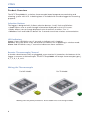
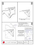
Product User Guide
VTMS
VTMS
Vaccine Temperature Monitoring System
Red 485
Dark Blue Pantone 289
Light Blue 58% of Pantone 289
To view the full MadgeTech product line,
visit our website at www.madgetech.com.
To view the full MadgeTech product line,
visit our website at www.madgetech.com.
Quick Start Steps
Product Operation (Wireless)
1.
Install the MadgeTech 4 Software and USB Drivers onto a PC.
2.
Plug an RFC1000 (sold separately) into a USB port on the base station computer.
(For transmissions over distances longer than 500’ indoors line of sight (2,000’
outdoors), plug additional RFC1000s into electrical outlets in between the base station
computer and the RFTCTemp2000A.) The red LED will illuminate on the RFC1000 to
signify that it has been connected correctly.
3.
Push and hold the wireless button on the RFTCTemp2000A for 5 seconds to
activate wireless communication. The display will confirm “Wireless: ON” and the
blue LED will blink every 40 seconds.
4.
Launch the MadgeTech Software, the RFTCTemp2000A icon will automatically appear in the connected devices list, showing that the device has been recognized.
Select the logger in the connected devices list, and click the “claim” button, wait
for the device to finish updating. Select the Realtime Start method from the device
tab and choose a desired reading rate from the drop-down menu and click “start”.
To set up or choose an Alarm for a Realtime Session, select the alarm rules tab (Refer
to the Alarm Settings section).
Product Operation (Plugged In)
1.
Install the MadgeTech 4 Software and USB Drivers onto a PC.
2.
Plug the USB to Mini USB cable (included with your logger) into a USB port on
your computer. With the wireless mode turned “OFF” on your device, plug the opposite end of the cable into the communication port on your RFTCTemp2000A.
3.
Launch the MadgeTech Software, the RFTCTemp2000A icon will automatically
appear in the software showing that the device is recognized. Select the logger in
the software and choose your desired start method.
4.
To download your data, select the device, click the stop button, and then click the
download button to view your report in the graph.
Questions?
For more details and instructions, please refer to the rest of this guide,
visit us online at www.madgetech.com or contact us for support at 603-456-2011.
1
VTMS
Product Overview
The RFTCTemp2000A is a wireless thermocouple based temperature monitoring and
alarming system with LCD. A docking base is included with the data logger for mounting
purposes.
Selection Buttons
The logger is designed with 3 direct selection buttons: Scroll, Units and Wireless.
• Scroll: Allows user to scroll through information displayed on the LCD Screen.
• Units: Allows user to change displayed units of measure to either °F or °C.
• Wireless: Push and hold this button for 5 seconds to activate wireless communication.
LED Indicators
Status: Green LED blinks every 5 seconds to indicate unit is logging.
Wireless: Blue LED blinks every 40 seconds to indicate unit is operating in wireless mode.
Alarm: Red LED blinks every 1 second to indicate an alarm condition.
Remote Thermocouple Channel
A female subminiature (SMP) or pluggable screw terminal is located on the bottom of the
logger to connect a thermocouple. The RFTCTemp2000A will accept thermocouple types J,
K, T, E, R, S, B, or N.
Wiring the Thermocouple
For MP Model: For TB Model:
Warning: Note the polarity instructions. Do not attach wires to the wrong terminals.
2
Product User Guide
Additional Features and Operation
Alarm Settings/Rules
1. To create an alarm rule, select Manage Rules in the device tab of the software.
2. Select New and enter a Rule name. Enter alarm the parameters using the drop down
menus and selection circles.
3. Select OK and choose the alarm to enable. The alarm bell is green when enabled and
red when disabled.
**Please refer to the Help file in the MadgeTech software for more information regarding alarm settings**
Trigger Settings
Application of trigger settings to the RFTCTemp2000A allows the device to omit excess
and/or unnecessary data.
1. Select the device from the Connected Devices section in the software.
2. Click the Properties button under the device tab at the top of the software.
3. Under the Trigger tab in the Properties window, you can select a single point (window)
or two point trigger.
4. To enable a high trigger, select Enable High Trigger and enter the desired high setpoint.
5. To enable a low trigger select Enable Low Trigger and enter the desired low setpoint.
6. To disable a high or low trigger, simply uncheck the applicable box.
7. Click Apply to apply the trigger settings to the RFTCTemp2000A.
Product Maintenance
Mounting Instructions
The base provided with your RFRHTemp2000A
can be used in two ways.
The bottom of the logger snaps in place to use
and mount the unit on a table top or horizontal
surface.
The base can also sucurely snap to the backside
of the logger for wall mounting if desired
(as shown right).
There are 2 holes in the base to allow for screws
for mounting.
3
VTMS
Battery Replacement
Materials: U9VL-J Battery
1. On the bottom of the enclosure, open the battery compartment by pulling in on the
cover tab.
2. Remove the battery by pulling it from the compartment.
3. Install the new battery, taking note of the polarity.
4. Push the cover closed until it clicks.
Recalibration
Standard recalibration for the RFTCTemp2000A is two points, 25°C and 60°C for
the internal channel (ambient), and 0mV for the thermocouple (remote) channel.
Recalibration is recommended annually for any MadgeTech data logger; a reminder is
automatically displayed in the software when the device is due. Use the RMA system to
submit your device for recalibration (Steps below).
Pricing:
RFTCTemp2000A (MP and TB models)
Recalibration traceable to NIST
$70.00
Recalibration $40.00
RMA Instructions
To send a device back in to MadgeTech, we ask that our customers go to the MadgeTech
website and create an RMA. To start this process, please follow the steps outlined below:
1. Visit www.madgetech.com, click on the Services tab, and select RMA Process.
2. When the web page opens, please sign in. If this is your first time creating an RMA,
select Create an Account and follow the on screen instructions. Once signed in, click on the
Make New RMA button and fill in all the blank fields.
3. Complete the applicable fields on the form including customer Billing and Shipping
information, even if they are the same.
5. Print out the confirmation page that follows containing the RMA number and
MadgeTech’s address for shipping. A Return Merchandise Authorization must be accompanied by a copy of the confirmation page, and shipping is prepaid by the customer. The
RMA number should be clearly marked on the outside of the package.
6. Please ship the package via UPS, FedEx, TNT, or DHL to the address listed on your confirmation page. USPS will not ship MadgeTech data loggers.
A notification email will be automatically sent when MadgeTech has received your RMA.
Once we receive your device(s), we will perform a free evaluation of the unit(s) before
contacting you (with a quote if requested). We shall await your confirmation before
proceeding with any work.
4
Product User Guide
Troubleshooting Tips
Why are my devices not appearing?
If your RFTCTemp2000A isn’t showing up in the Connected devices panel, or you receive an error message while using the RFTCTemp2000A, try the following:
• Check that your RFC1000 is properly connected. For more information, see Troubleshooting Interface
Cable problems (below)
• Ensure that the battery is not discharged. For best voltage accuracy, use a voltage meter connected to
the battery of the device. If you have one available, try switching the battery with a fresh 9V lithium.
• Ensure that no other MadgeTech software (such as MadgeTech 2, or MadgeNET) is running in the
background
• Ensure that you are using MadgeTech version 4. MadgeTech 2 and MadgeNET are not the correct
software for connecting with the RFTCTemp2000A
• Ensure that the Connected Devices panel is large enough to display devices. This can be verified by
positioning the cursor on the edge of the Connected Devices panel until the resize cursor appears, then
dragging the edge of the panel to resize it
Troubleshooting Interface Cable problems
Check that the software recognizes your RFC1000 wireless receiver
If your device is not appearing in the Connected Devices list, it may be that the RFC1000 is not properly
connected.
1. In the software, click the File Button , then click Options.
2. In the Options window, click Communications.
3. The Detected Interfaces box will list all of the available communication interfaces. If your RFC1000 is
listed there, then the software has correctly recognized and is ready to use it.
Check that Windows recognizes your RFC1000 wireless receiver
If the software does not recognise your RFC1000, there may be a problem with Windows or the USB
drivers.
1. In Windows, click Start, right-click Computer and choose Properties or you can press Windows+Break
as a keyboard shortcut.
2. Click Device Manager in the left hand column.
3. Double click Universal Serial Bus Controllers.
4. Look for an entry for Datalogger Interface.
5. If the entry is present, and there are no warning messages or icons, then windows has correctly
recognized your RFC1000.
6. If the entry is not present, or has an exclamation point icon next to it, you may need to install the
USB drivers. These are available on your software flash drive, and on the MadgeTech website.
Ensure that the USB end of the RFC1000 is securely connected to the computer
1. Locate the USB-A plug of your RFC1000
2. If the interface cable is connected to your PC, unplug it
3. Wait ten seconds, then reinsert it
4. Check to make sure that the red LED is lit, indicating a successful connection.
Still need help?
For more troubleshooting tips and information, refer to the
built in help section of the MadgeTech 4 software , visit our Knowledge Base online at
www.madgetech.com/kbase or contact us for customer support at 603-456-2011.
Part Number
RFTCTemp2000A
Internal Temperature Sensor
Semiconductor
Internal Temperature Range
-20 to +60°C (-4°F to +140°F)
Internal Temperature Resolution
0.1°C (0.18°F)
Remote Channel Temperature Sensor
Range, Resolution & Accuracy
*See Table below for Details
Cold Jct. Compensation
Automatic based on internal channel
Memory
16,128/channel
Sample Rate
1 second up to 24 hours
Channels
Required Interface Package
1 Internal & 1 Remote
RFC1000 (wireless); USB to Mini USB Cable
Baud Rate
250,000
Typical Battery Life
3 years typical at 1 minute reading rate
Operating Environment
-20 to +60°C (-4°F to +140°F)
Material
Dimensions
Wireless Range
ABS Plastic
3.0” x 3.5” x 0.95” (76.2mm x 88.9mm x 24.1mm) Data logger only; does not include docking base
2000’ max. outdoors (line of sight unobstructed)
500’ max indoors (typical urban)
* Remote Channel Range, Resolution & Accuracy
Thermocouple
Range (°C)
J
-210 to +760
K
-270 to +1370
T
-270 to +400
E
-270 to +980
R
-50 to +1760
S
-50 to +1760
B
+50 to +1820
N
-270 to +1300
Resolution
0.1°C
0.1°C
0.1°C
0.1°C
0.5°C
0.5°C
0.5°C
0.1°C
Accuracy
+0.5°C
+0.5°C
+0.5°C
+0.5°C
+2.0°C
+2.0°C
+2.0°C
+0.5°C
Battery Warning
WARNING: MAY LEAK, FLAME OR EXPLODE IF DISASSEMBLED, SHORTED, CHARGED,
CONNECTED TOGETHER, MIXED WITH USED OR OTHER BATTERIES, AND/OR EXPOSED TO FIRE/
HIGH TEMPERATURE. DISCARD USED BATTERY PROMPTLY, KEEP OUT OF REACH OF CHILDREN.
Specifications subject to change.
See MadgeTech’s terms and conditions at www.madgetech.com
MadgeTech, Inc.
6 Warner Road l Warner, NH 03278
Phone 603.456.2011 l Fax 603.456.2012
www.madgetech.com l [email protected]
DOC-1260036-00 REV 2 2013.01.02