1
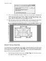
ARCON User Guide
Produced and published in the UK
by Eleco Software Limited
© 2013 Eleco plc. All rights reserved.
The software and hardware names and labels used in this document are generally protected trademarks of
their respective owners.
All data and programs described in this document were compiled and/or arranged by the authors with
utmost care and reproduced under adherence to proper and effective control measures. Nevertheless, there
may be errors. Therefore, Eleco Software Limited would like to point out that neither a warranty, legal
responsibility, nor any liability for consequences of using the software or documentation can be ascribed to
the publisher, or the distributor.
No part of this document may be reproduced, stored in a retrieval system, or transmitted by any means,
electronic, mechanical, photocopying, recording or otherwise, without the prior permission of the publisher.
1
ARCON User Guide
2
Contents
Contents
Welcome .................................................................................................................. 5
Installing ARCON .................................................................................................... 7
If Setup Does Not Launch Automatically .......................................................... 7
Licence Agreement .......................................................................................... 7
Setup Type ....................................................................................................... 7
Ready to Install ................................................................................................ 8
Copying ARCON Files ..................................................................................... 8
Completing Setup............................................................................................. 8
Product Activation ................................................................................................ 8
Online Help........................................................................................................... 9
ARCON: The Basics ............................................................................................. 11
Understanding the Interface ............................................................................... 12
Open Project ...................................................................................................... 12
Save Project ....................................................................................................... 13
2D Construction Mode ........................................................................................ 13
3D Design Mode ................................................................................................. 13
New Project ........................................................................................................ 14
Optional Changes to ARCON ............................................................................. 15
Backups ......................................................................................................... 15
Tutorial: Getting Started in ARCON .................................................................... 17
Creating a New Project....................................................................................... 17
Entering Measurements ..................................................................................... 19
Adding the Walls ................................................................................................ 23
Inserting Doors & Windows ................................................................................ 26
Placing a Staircase ............................................................................................. 29
Additional Floors................................................................................................. 32
Adding a Roof to the Building ............................................................................. 36
Editing the Roof ............................................................................................. 42
Roof Editor – Simple Roof Type ..................................................................... 42
Roof Editor – Advanced Roof Editor .............................................................. 44
Roof Features: Dormer Windows ....................................................................... 47
Roof Features: Skylights and Velux Windows .................................................... 51
Adding Solar Panels and Other Objects ............................................................. 54
Copying Objects ................................................................................................. 60
Adding Textures ................................................................................................. 60
Viewing Shadow Detail and Sun Positioning ...................................................... 62
Online Support Documents ................................................................................. 65
3
ARCON User Guide
4
Welcome
Welcome
This guide has been created for users of all levels and is ideal for anyone new to
ARCON, experienced users looking for some suggested methods or for prospective
users who want to see how easy ARCON can be.
This guide will not teach you architecture, interior design, drawing or building
methods, it will teach you how to use ARCON. After practice, you will soon realise
how effective ARCON is as a design and visualisation tool.
The screenshots in this guide may differ from your own depending on the Windows
operating system and product version you are running.
Please note that this guide will only teach you the basics of ARCON. If you need
more details on a particular function in ARCON, you should refer to the PDF
manuals on the ARCON DVD, context sensitive help system in the software or visit
the support section on our website www.3darchitect.co.uk.
If you experience problems viewing the PDF files found on the ARCON DVD then
that’s possibly due to you using an older version of Adobe Reader. You can
download the latest version of Adobe Reader from www.adobe.com
We would also like to thank Custom Homes Ltd for allowing us to use some of their
house designs from their catalogue.
5
ARCON User Guide
6
Setup
Installing ARCON
NOTE: Whilst every effort is undertaken to ensure that all of our software is
quick and easy to install, occasionally different computer configurations can
cause rare issues. These generally occur when anti-virus software is used
during the installation process; preventing some files from being correctly
registered.
To help avoid such issues, temporarily disable your anti-virus software
before starting the installation process and once complete, you can then reactivate your anti-virus software.
To install ARCON you must run the Setup. Insert the disc into your drive. If Autorun
is enabled Setup will launch automatically.
If Setup Does Not Launch Automatically
Autorun may be turned off on your computer. On the Windows Start menu, select
Run and enter D:\Setup.exe (where D: is your drive).
After Setup has launched, a Welcome dialog box appears. Click the Next button to
continue.
Licence Agreement
With the purchase of ARCON you are presented with a Software License
Agreement. Please read the License Agreement carefully before you accept it. Click
Next to continue.
Setup Type
After entering your User and Company name click Next to continue to the Setup
Type dialog box.
ARCON can be installed on your computer in two different ways. The Typical setup
will install all common components. In the Compact setup, objects, textures, videos
and demo files are not installed to the computer’s hard drive, but are accessed from
the disc. Regardless of the type of setup, you’ll be asked to select and confirm a
destination folder on your hard disk where the files will be copied. You may leave
this destination as the default or change this to a desired path. Click Next to
continue.
7
ARCON User Guide
Ready to Install
Click Install to proceed with the install as chosen. Click Back to amend any
choices.
Copying ARCON Files
During copying, a progress bar is displayed to show the progress of the install.
The time required to copy the files depends upon the speed of your computer and
whether you have selected a Typical or Compact setup.
Completing Setup
Finally upon successfully completing the installation of ARCON, a final dialog box
appears. Click Finish to complete the program setup.
A completed setup displays the following icons in the ARCON program folder:
Starts ARCON program
Help Files
Manuals
Web Links
Product Activation
The activation technology integrated into your product is intended to prevent illegal
copying and distribution of software and it is an additional means allowing us to
provide customers with confidence in the quality of the product purchased.
In order to launch ARCON in full you are required to activate it by entering the
Serial Number supplied with the purchased product (normally located on the outside
cover of this guide). We recommend that you activate ARCON as soon as you have
installed it.
When you start ARCON for the first time, the opening activation dialog box will
appear.
To automatically activate ARCON, please follow the on-screen instructions.
8
Setup
NOTE: Always check that you have entered your Serial Number correctly
before starting the activation process.
If the automatic activation process succeeds then you will be able to launch
ARCON in the normal way.
NOTE: You will need a stable internet connection for automatic activation. If
you have not been able to connect to the activation server due to internet
connection problems, then you will be required to activate the product
manually by following the on-screen instructions.
Online Help
ARCON has detailed online Help that can assist you whenever you are unsure
about a certain function, icon etc. You have several ways of accessing ARCON
help.
First you can press the F1 function key. You can press F1 at any time; ARCON
contents page will open, from which you can select a topic of your choice. Pressing
F1 has the same effect as selecting Contents from the Help menu.
The second way to receive help is to select the menu option Index in the Help
menu. Here you can enter a keyword to search for the online help file will present a
list of every occurrence of that word in the file.
The third way is to click the
icon. If you click this icon your mouse pointer
changes to a mouse pointer with an attached question mark. With this, click the
place you would like to receive information. ARCON jumps to the appropriate place
in the help file and displays the information on screen.
Finally, there is help as you move the mouse around the ARCON window. As you
move the mouse over icons, descriptions are displayed at the bottom of the window
in the status bar. Also, if you hold the mouse over an icon for a second, pop-up help
text is displayed to help you identify the function of each icon. This feature can be
switched off from the Help menu.
9
ARCON User Guide
10
Basics
ARCON: The Basics
If you are a new user you should work through this chapter first before you embark
on the next tutorial. Here we will concentrate on the fundamentals of ARCON.
After having installed ARCON, start the program and after a short while the
following screen will appear:
This screen will vary depending upon your operating system, ARCON version, addon modules installed and screen resolution.
NOTE: There are no projects loaded at the moment!
If you can’t see the Help menu in the top menu bar, then it’s possible that you are
running in a low screen resolution and you will need to increase it. If you are
running in the highest resolution allowed by your computer then it’s possible to
‘grab’ the menu bar and slide it until the Help menu comes into view.
The same may apply to your vertical icon bar, especially in later versions of
ARCON, which have additional tools. Grab this vertical bar and slide the icon bar
upwards. To check this, activate the 2D Graphics Editor from the Macro menu and
11
ARCON User Guide
ensure that you can see the new 2D Graphics Editor icon appear at the bottom of
the left vertical icon bar.
Understanding the Interface
The ARCON interface is very easy to work around once you gain an understanding
on how to locate dialog boxes for editing. There are 2 simple ways to access dialog
boxes. The first is to right-click menu items to open dialog boxes. This will allow you
to easily set default settings and/or make adjustments before adding elements to
your project e.g. adjust wall depth before drawing.
The second method of accessing dialog boxes is to select and double-click
elements that you have drawn e.g. left-clicking a wall in your project. When
highlighted in red, double-click (left mouse button) to open the dialog box to make
changes. Selecting different elements that are overlapping can be achieved by
single-clicking over the element until it highlights in red. Provided you keep the
mouse cursor in the same position, you will notice each layered element highlight in
red.
Open Project
To open an existing project, click the menu File> Open
The Project dialog will then display. For example, in
Eleco\ARCON\Projects\Tutorial project folder locate
the file Tenterden07.acp. All ARCON project files
end with the suffix .acp and are displayed in the list
of files available. Click the file Tenterden07.acp and
then click OK.
The project will load and you will then be displayed
with the following screen:
12
Basics
Note: If your project loads a 3D view then press F12 key.
Save Project
To save a project at any time, select the menu File> Save. If you want to save the
file as a new name, then select File> Save as…
2D Construction Mode
Pressing F12 will switch between 2D and 3D modes. The 2D Construction mode is
used to construct your project and can be best described as the plan mode. Like
you would draw a house plan, the 2D mode is a bird’s eye view of your project laid
out on your workspace or page. Walls, doors, windows, roof, etc. are positioned in
the 2D mode by placing them into position from the icon bars. Dialog boxes will
appear allowing you to easily adjust settings for each element. All changes in your
2D plan are automatically calculated in the 3D mode.
3D Design Mode
In 3D mode you can add 3D objects such as architectural features and furniture.
You can also drag textures from the catalogue onto walls, floors etc.
13
ARCON User Guide
Clicking the following icon activates the catalogue:
Objects, textures etc can be selected from the catalogue and dragged into the
project.
Switch to the Texture catalogue by clicking the Texture icon. From the Texture
catalogue you can now drag textures onto walls, roof etc.
There is an alternative
view to help you
navigate around the
Object and texture
catalogue. To the left
of the object/texture
icons, there is a split
window bar. Drag this
bar to the right to
display a Windows
Explorer:
New Project
To create a new project from scratch,
click the menu entry File> New and
you will be presented with the Floor
properties dialog. This dialog is used
to define your floor to floor height, but
for the moment we will accept the
defaults and click OK.
14
Basics
Optional Changes to ARCON
Backups
Most of these options exist in the Options menu. The most important is the backup
option. No matter what software you use, you will eventually lose data, either due to
hardware error, loss of power, human error or software error. It will happen! So
please always make regular backups. ARCON can help you do this automatically.
Click Options> Program> Save to activate the Save options dialog.
In addition to activating the Automatic save function to e.g. every 15 minutes, it is
advisable to create a backup copy too (check this box). It is also useful to save
your project at different stages, so a regular save of e.g. myproject001.acp, and
then myproject002.acp etc will mean that you can always return to a known project
state e.g.
•
Guidelines – myproject001.acp
•
Walls – myproject002.acp
•
Windows & doors – myproject003.acp
15
ARCON User Guide
16
Getting Started
Tutorial: Getting Started in ARCON
In this tutorial we will guide you through the basic functions required to draw a multistorey building and for viewing in 3D. You will learn about:
•
•
•
•
•
•
Creating a new project
Entering measurements
Adding walls
Inserting doors & windows
Placing a staircase
Additional floors
•
Adding a roof to the building
•
•
•
•
•
•
Editing the roof
Dormer windows, skylights and velux windows
Adding solar panels and other objects
Copying objects
Adding textures
Viewing shadow detail and sun positioning
This tutorial will help you to get started in ARCON and once you have learned about
the above tools and drawing methods you can apply these to your own building
design project.
Creating a New Project
In order to start with our drawing, we have to initially create a new project and
establish the project settings which will define the parameters of our drawing.
1.
2.
3.
Navigate to the File menu.
Select New
You will be presented with
a dialog box to confirm the
floor properties of the
initial floor of your new
building:
17
ARCON User Guide
4.
5.
In the Floor Properties dialog box we need to select the following fields:
a. Name – either select the correct floor name from the drop down
list, or type a new one in this box. Using meaningful and correct
floor names will aid navigation through projects as they become
larger and more complex.
b. Floor to floor height – this will help determine the height of your
walls in 3D. Floor to floor height represents the measurement
from the floor surface of the floor we are creating, to the floor
surface of the level above. To calculate floor to ceiling height you
would need to subtract the values in the Ceiling measurements
box from the Floor to floor height
c. Height above ground floor level – if required this can be set to
an appropriate measurement either positive for raised properties
or negative for underground builds.
When these settings are correct, click OK to open your blank workspace.
Don’t worry about the accuracy of these settings if they are unknown as
they can be edited at any time.
You will now be presented with an empty workspace on which your drawing will
exist. However before we start with the drawing we need to check the scale
and paper size settings are correct and appropriate for our requirements.
1.
2.
3.
4.
Navigate to File
Select Project Options, the
following dialog box will
open:
Using the radio buttons next
to the options, we can select
our paper size, the scale the
project will be drawn at and
the measurement units for
the project. These settings
can again all be changed at
anytime so it is always
possible
to
change
scale/size or metric/imperial
measurements and different
unit types.
Under Paper Format select
Use Printer Default and
then press the Print Setup
button. In the dialog box that
18
Getting Started
5.
6.
opens, choose the paper type and orientation that you would like to print
your projects to. The page on screen will then adjust to match your chosen
printer settings.
Select the required Scale (for most plans this will be 1:100) and the
measurement units you wish to use (this would normally be mm)
If you want to use these settings as your default for future projects, select
Set as default then press OK to return to your newly formatted project
page.
Entering Measurements
With the ARCON software there are often multiple methods that can be used to
achieve the same outcome. Providing multiple options for producing the same end
goal enables the user to select a working method that suits their own style. For the
purposes of entering our dimensions of the floor plans, we can achieve this in a
number of ways. The method detailed below is just one option, although it is seen
by most users as the fastest and most accurate way of creating an accurate floor
plan.
In the method we will use below, we initially ignore the placement of walls. Instead,
we will mark out our known measurements using the Guideline tool.
1.
From the left-hand toolbar locate and click on the Guideline tool.
2.
Clicking on the Guideline tool will display a new set of options on the
inside left toolbar.
19
ARCON User Guide
3.
4.
5.
6.
Each of the icons displayed in this toolset represent a different placement
method or type of Guideline. We will now use a combination of these
Guidelines in order to place our known measurements.
As we will be dealing with real world measurements, we need to ensure
that the guidelines we place are accurate. The first thing we need to do is
place a reference point on our drawing to measure from (this method is the
same for working with either internal or external measurements).
Firstly we will place a Vertical Guideline on the left-hand side of our page.
To do this left click on the Vertical Guideline icon on the inside left toolbar
With the Vertical Guideline selected, move your cursor onto the drawing
area of you page. As you move your cursor onto the page you will see that
the cursor is now accompanied by a vertical line. This line represents our
Vertical Guideline. To place the Guideline left-click the mouse. Your
page should now have a single Guideline which runs the full height of the
page.
20
Getting Started
7.
Ok, we now have a reference point on the page for any vertical
measurements, we now need to add in a Horizontal Guideline. Follow
steps 5 and 6 above to place a Horizontal Guideline, making sure to
select the Horizontal Guideline in place of the Vertical Guideline. Place
your Horizontal Guideline near the top edge of the page, which should
now look like this:
21
ARCON User Guide
8.
Having placed both a Vertical Guideline and a Horizontal Guideline we
have created a reference point from which we can measure all of the
dimensions needed to create the footprint of the building.
9. We will now place Guidelines at all of the ends of the measurements that
we know to create an accurate scaled plan of the building.
10. To place our first known measurement we will use the Set Distance
Parallel Guideline. Select this from the left-hand toolbar by clicking on the
icon:
11. The Set Distance Parallel Guideline differs from the standard Vertical
and Horizontal Guidelines that we have already placed in that it requires
a reference point to measure from.
12. To place our Set Distance Parallel Guideline we need to move the cursor
back onto our page. Move your cursor towards the Vertical Guideline we
placed earlier. As you move your cursor close to this guide, the cursor will
snap to the guide which will then highlight (N.B. the highlight colour will
depend upon the guideline colour. The highlight colour for black is white,
so the guide will effectively ‘disappear’.)
13. To select the Vertical Guideline as our reference, with the mouse cursor
highlighting this guide, left click. This locks this position as the ‘measure
from’ point. (N.B. the Snap function must be turned on for this tool to
function correctly.)
14. Once the ‘measure from’ point is set, move your mouse in the general
direction of the next measurement. As we are using a parallel guide and
referencing a Vertical Guideline we will only be able to move left or right
across the page.
15. Now we can left click on the page again. Doing this will open a dialog box
asking for entry of the dimension. This is the measurement we wish to use
from our baseline:
22
Getting Started
16. In the highlighted box, type the measurement you wish to enter and click
OK. A new guideline will now be placed on your page which is the exact
distance specified from the reference point.
17. By repeating steps 12-16 for each known measurement of our floor plan,
we can very quickly build a series of intersecting guidelines which reflect
the accurate measurements to the scale of our project.
Adding the Walls
As with any construction, we need to create the walls that create our building and
on which the roof will sit. By using the guideline placement method detailed above,
we can use a very simple method to place the walls, effectively tracing around the
edge of our guidelines to create a measured, accurate floor plan.
1.
Firstly we need to select the wall tool and the placement method. So to
begin, left-click on the Wall tool on the left-hand toolbar.
2.
Clicking on the Wall tool will display the placement options
on the inside left toolbar.
Each of the icons displayed in the toolset represent a
different placement method to draw a Wall. As we have
already laid out our floor plan, we will only need to use one of
these tools.
The tool we are going to use in the Multiple Walls tool. To
select this tool, left click on the icon.
3.
4.
23
ARCON User Guide
5.
6.
7.
8.
With the Multiple Walls tool selected, we can now begin to draw the floor
plan by tracing the Guidelines already placed on the page
Firstly, move your mouse to the first intersection of your Guidelines, this
will be our starting point.
Left-click once to place the start of you wall and drag the mouse towards
the next intersection where the end of the wall will be (Note: At this point
DO NOT left-click to place the end of the wall).
As you will see from the screen, when you draw your mouse across the
page, a ghost image of the wall you are going to create (together with its
dimensions) follows the cursor. When looking closely you should also be
able to see that by default, walls are drawn along the centre line of their
depth (thickness).
9.
Obviously, this can create problems when using internal or external
measurements as you will end up with half the wall depth inside/outside
your guidelines, stopping the drawings from being accurate to the
measurements we placed earlier.
10. Therefore, before we place the end of this wall (and carry on with the
remainder of the floor plan) we need to define which edge of the wall we
want to draw along.
11. To do this we simply press CTRL+W. This key combination enables you to
toggle between the centre line of the wall, the inside edge and the outside
24
Getting Started
edge. Try pressing this key combination a few times to see the effect on
screen. Use CTRL+W to select the outside edge as the drawing edge.
12. With the correct edge selected, complete the first wall by left clicking to
place the end point.
13. As we are using the Multiple Walls tool, you will notice that finishing our
first wall automatically gives us the start point for the next wall. Also as we
have already set the wall to draw on the correct edge, this setting remains
in place until we cancel the tool.
14. Now it’s simply a case of following your guidelines to place wall finish/start
points at all of the correct intersection points until you get back to where
you began and the floor plan is completed.
15. You will notice that when your final wall connects back to your start point,
the room is automatically labelled ‘Room 1’. This is an important part of
the checking process when drawing in ARCON. The room label confirms
that all of your walls connect, with no gaps or spaces, to form a fully
25
ARCON User Guide
contained room. Once walls connect like this they are a room, which
means that the floor and ceiling are created. If the walls do not connect,
then no floor or ceiling will be added. Room labels can always be changed
to more meaningful names.
16. At this stage, you could now go on to split the floor plan into smaller
spaces using internal walls, add doors and windows, stairs and other
architectural features. However, as we are primarily concerned with
creating the roof structure we will just use the outside floor plan we have
created.
Inserting Doors & Windows
With your external and internal walls in place it is generally now that we would place
the remaining construction items in the first floor we have completed. Although you
can add these details at any time, adding them in at this stage means you can then
copy the details to other floors if required, saving time.
We will start with adding doors and windows into the project. The basic principles
for adding doors and windows are the same. The following steps will cover placing
a window into the project using one of the selected window types. The process for
placing different windows or doors will be the same although some of the
customisation options vary depending upon the model of door or window chosen.
1.
2.
3.
4.
5.
6.
The first thing to understand with both Doors and Windows is that they
need to be placed into an existing Wall.
With the Wall in place, we need to select the Window type we want to
use. Do not worry about leaving or creating an opening for the Window in
the Wall, this will be created automatically when placing the Window.
Initially we need to select the Window type from the Window menu.
Hover your mouse over the Window icon on the left hand toolbar, the flyout menu will be displayed:
Each icon on the fly-out menu represents a
different style or type of Window.
Like Doors, Windows vary in their
complexity meaning that some types have
more variables that can be changed than
others. Particular attention should be paid to
the first four options (Simple Windows,
Advanced
Window,
Window
with
Fanlight, Window Macro) as these contain
the most complex set of variables enabling
the more complex designs to be created.
26
Getting Started
7.
8.
9.
For this example we are going to use the Window Macro type. So left
click the Window Macro to select it.
The fly-out menu will be closed and you should notice that the Window
icon on the left toolbar has now changed to show the active type as
Window Macro.
As with all tools in ARCON, we can now right click on the Window icon to
open the properties dialog box:
10. As we have selected the Window Macro type, the dialog box that opens is
specific to this type of Window. With this particular type, you can select a
new style from the sub-menu on the left (any Windows created in the
Door/Window Macro Designer will also appear in this sub-menu).
11. Make any adjustments you need to the style and size of the Window and
when finished click OK.
12. With the Window set to the correct size we now need to left-click on the
Window Icon to activate this tool.
13. You should now see three placement options for inserting this Window
appear on the inside left toolbar:
27
ARCON User Guide
14. Each of these options represents a slightly different method for placing the
Window into the wall. Window, Free Position enables you to use a drag
and drop action to simply click on the spot the want to place the Window.
Window Position at Set Distance enables a reference point to be
selected and then a distance entered to determine how far from the
reference point the Window should be placed. Finally, Window Midway
functions like all ‘midway’ options within the software and allows you to
define two points with the Window being placed exactly centred between
these two points. You should use whichever of these methods is
appropriate for your particular situation.
15. For this example I will use Window, Free Position. With this option
selected, move your cursor over to your project page. You will see that as
you hover over a wall the outline of the window appears where your cursor
is located:
16. If you move your cursor off a wall, the option to place the Window will no
longer be valid.
17. When you are happy that the Window is in the correct position, left click to
lock it into place.
28
Getting Started
18. Before the Window is finalised we need to define which way the Window
will open (i.e. windows swing/window note). The four symbols that appear
show the different available opening directions:
19. Move you cursor between the swing options to highlight the required
option in red. Once you have chosen the appropriate opening side, left
click to finish and place the Window.
20. You can now repeat these steps for your remaining Windows or copy this
process to place Doors, simply substituting the Window Type with a
chosen Door Type.
Placing a Staircase
Once your ground floor is complete, it is likely that your building will be multi-storey.
We will need to add additional floors to the building shortly, but first we will add a
staircase to link the floors together.
Within ARCON we can define numerous styles of staircase from the available
options and we retain full control of depth, width, number of steps and even the start
and end heights. These are all fully adjustable meaning complex stair configurations
can be created. For the majority of cases however, a simple floor-to-floor staircase
is all that is required. This basic guide covers placing a single staircase to link two
floors.
29
ARCON User Guide
1. To begin, we first need to select the Staircase type that we want to use.
2. We can select the Staircase by hovering the cursor over the Stairs icon
on the left-hand toolbar. This opens the fly-out menu which shows the
Staircase options available:
3. The Staircases are formed into two columns. These represent the
construction type, either timber or concrete. The Staircase types within
each column are identical in their shapes (with the exception of the spiral
staircase and ramp construction options).
4. As with all tools, we can right-click on the Staircase icon for the design we
want to use to set the properties. However, with Stairs it is generally more
logical to place the Staircase first and then make any changes to the
properties.
5. So to begin with select the Staircase style you wish to use by left-clicking
the appropriate icon.
6. With the Staircase selected, move your cursor into your project page
space, you should now see that your cursor now has a ‘ghost’ outline of
the Staircase shape attached to it:
30
Getting Started
7. We now need to place the Staircase into the room.
8. Stairs are placed with a ‘three-click’ system. The three clicks are used to
effectively form an L-shape with the cursor which will define the length
from the base of the Staircase to the furthest point and then the width.
This process can easily be simplified by making use of Guidelines to mark
out known measurements before placing the Stairs.
9. As you can see from the position of the cursor in relation to the ‘ghost’
Staircase, the first point we lock into position is the bottom corner (at this
stage it doesn’t matter if this is the left or right corner as we will define that
with the third click). Click once to place the bottom corner.
10. Your cursor movement is now restricted and we need to place the second
click. The second click represents the furthest point (length) of the
Staircase from the bottom corner (first click). This would be the full length
of the Stairs if using a straight Staircase but my just be the furthest point if
using L or U shaped Stairs.
11. With the second point in place, we can now only move left or right to place
the third click. Again with a straight Staircase this would give us the width.
With an L or U shaped Staircase this will be the distance to the top.
12. Once the Staircase has been entered onto the plan with the three click
method the Stairs dialog box will open to show the default settings for the
Staircase.
31
ARCON User Guide
13. By default the Stairs will run from the floor level to the floor surface of the
floor above. You can of course amend any of the settings to change the
start and end heights as well as changing the depth, width and number of
steps.
14. Click OK to accept these settings. Your Staircase will be added to your
floorplan, complete with automatic cut-out for the ceiling above.
Additional Floors
Once the ground floor has been created, we will need to add any additional floors
that are relevant to the building we are modelling. In the majority of cases we will
probably be adding between 1 and 3 new floors. The reason for this is that we
almost always treat the roof as the top floor of the house, so we have to create an
attic floor for the roof to sit on. See below:
32
Getting Started
As demonstrated above, the attic floor is created as with any new floor, the roof
settings we apply to that floor will then determine how much or how little of the walls
of the attic floor we actually see. This will be explained further when we look at
placing the roof.
From the footprint of the building we have created so far, we will create a standard
two storey house. This means that we need to add an additional two floors (one for
the first floor and one for the attic) to our existing ground floor. The process for
adding each floor is the same.
1.
2.
From the top menu bar, navigate to Floor and left click to expand the
options contained in this menu.
As we are currently working on the ground floor, select New Floor Above
Current. This option always enables us to place a new floor directly above
the currently active floor and is the option you will use on most occasions
when adding a new floor. You will then be presented with the following
dialog box:
33
ARCON User Guide
3.
4.
5.
As you can see this looks very similar to the dialog box we saw when we
defined our ground floor options at the start of the project. As we are now
starting a new floor, we get to define these options again as the new floor
may have different settings to the floor below.
In addition to changing the floor properties, you will see that we also have
a tab labelled Transfer, which was not present when we setup our ground
floor at the start of the project.
Left click on the Transfer tab to view the options available:
34
Getting Started
6.
7.
8.
The selection boxes available in this tab enable you to specify the Source
to copy from together with what we will copy to the new floor. The options
to transfer are:
a. None – Creates a new blank floor on which we can start drawing
again. This is useful if the upper floor of the building is completely
different in layout to the ground floor.
b. Complete Floor – Creates an identical copy of the Source floor
including fixtures and fittings, ideal for creating duplicates of
apartments.
c. Floor Plan Only – Creates a copy of all the walls from the
Source floor and as we have only created walls in our plan, this
will be the option we need to choose.
d. Floor Plan With – Selecting this option opens up all of the tick
boxes below and enables us to choose which elements are
copied from the Source floor.
Ensure that the option Floor Plan Only is selected and click OK
A new floor has now been added to our plan and is now the active floor we
are working on.
35
ARCON User Guide
9.
At this stage we have two floors to our building. We now need to add the
final floor for our attic. To do this, simply repeat steps 1 to 8, making sure
to select Floor Plan Only again and change the name of the new floor to
‘Attic’. Having added this third floor to our building, we can now place our
roof.
Adding a Roof to the Building
Roofs can be added to the building in a variety of ways, and the best method to use
will depend on the type, complexity and style of the roof. As creating an accurate
representation of the roof structure and style is of paramount importance to
visualisation of solar panels, we will look at all of the different methods for roof
placement.
Method 1: Automatic Roof
The simplest of all the methods of adding a roof to the building is by using an
automatic roof placement option. This option allows us to very quickly place a
standard hipped roof onto our building. The settings of this roof can then be
changed to alter all aspects of the style and design (See section Editing Roofs).
1.
Firstly we need to select the Roof Type from the Roof Type icon menu on
the left-hand toolbar. Hovering over the icon will display the fly-out menu
showing the Roof Type options available:
2.
For this method we will select the first option on the top left of the fly-out
menu, Freeform Roof.
Choosing the Freeform Roof then displays three options on the inside left
toolbar, which represent the different methods available for placing the roof
onto the building:
3.
36
Getting Started
4.
5.
6.
We need to left-click on the middle icon, which allows us to use the
Automatic Roof.
With the Automatic Roof option selected, simply move your cursor back
onto your floor plan (Note: Make sure you have the Attic floor selected as
the active floor before starting to place your roof).
As you move your cursor over any of the walls of your building, the whole
floor plan will be highlighted with a red outline:
7.
This red outline, highlights the section of the floor plan (generally the whole
plan) over which the roof will be drawn.
8. Now simply left click once and your roof will be drawn with default settings.
9. You will now be presented with the Roof Editor, which enables you to now
make changes to the type of roof and the roof settings. The use of the
Roof Editor will be covered in a later section, so at this stage click the OK
button.
10. Depending upon the size of the property and the roof settings, the
following message may appear on screen:
37
ARCON User Guide
11. This is an information message, rather than an error and is designed to
inform you that the apex of the roof is higher than the walls the roof sits on.
If this message does appear at this stage, click OK. We will look at the
effects and the resolution to solve the problem later on.
12. We now have a roof on our building, and in the standard 2D floor plan
view, you should now be able to see the structure of the placed roof:
Method 2: Placing a Simple Roof
If the roof that you are modelling is very simple, it may be quicker to use one of the
preset roof types available from the Roof Type menu. Using the preset roofs allows
us to find the correct roof style right away. These roofs have fewer editable options
but you retain full control over pitch, height etc.
1.
By hovering you mouse cursor over the Roof Type icon, the fly out menu
will show the simple roof styles available:
38
Getting Started
2.
As we have already seen in Method 1 above, the first icon represents the
Freeform Roof. For the simple roof type we ignore this icon and choose
from one of the other standard roof styles:
3.
Although all of the roof styles available vary greatly in structure and
editable settings, the basic principle of placing these Roof Types is the
same regardless of which type is chosen.
From the fly out menu, left click on the Gable Roof icon to select it.
We now have two options to place the Gable Roof. You will see that one
of these is the Automatic Roof option that we used to add our Freeform
Roof earlier. This works in the same way except the roof editor options will
be specific to the roof type we are placing. However, on this occasion we
4.
5.
39
ARCON User Guide
are going to use the Rectangular Roof placement option. To select it, left
click on the icon:
6.
By choosing the Rectangular Roof option, we now need to define the
space that we wish the roof to cover. Unlike the Automatic Roof option,
placing with this method does not require you to produce any walls.
Accordingly if you prefer you can simply use your guidelines for
measurements and then draw only a roof.
7. For simplicity, navigate to a part of your page that currently has empty
space (i.e. no walls, or roof).
8. Left click once to place the first corner of the Rectangular Roof. This first
point now represents the top left corner of the roof as we look down onto
the page.
9. Move your mouse cursor right and down across the page. You will see that
the outline of the roof shape is being created as a rectangle.
10. Continue until you reach the point that will be your bottom right corner of
the roof (Note: Normally we would be using walls or guidelines to ensure
sizing is correct). Left click again to set this opposite corner.
11. Your Gable Roof will now be created and the appropriate Roof Editor
dialog box will be displayed. Again, as we will look at the Roof Editor
shortly, simply click OK at this stage to place your roof on the page.
Method 3: Creating the Roof Shape Manually
There will of course, always be occasions where a standard roof shape is
inappropriate, or the shape of the roof differs from the shape of the floor plan. On
these occasions it may be necessary to manually define the roof shape by placing a
series of points to define the corners.
1.
Firstly we need to select the Roof Type from the Roof Type icon menu on
the left-hand toolbar. Hovering over the icon will display the fly-out menu
showing the Roof Type options available:
40
Getting Started
2.
3.
For this method we need to select the first option on the top left of the flyout menu, Freeform Roof.
Choosing the Freeform Roof then displays three options on the inside left
toolbar, which represent the different methods available for placing the roof
onto the building:
4.
The final option of the three is to place a Roof from Polygon Marks. This
option is only available with the Freeform Roof type.
5. To add the roof, we need to now place a single polygon mark at each point
where we need a roof corner to be.
6. Moving our mouse cursor to the first (top left for example) corner of the
building, left click once to place the first polygon mark.
7. Now move your cursor to the next corner and left click again to place the
next polygon mark. Repeat this process until you have completed the
shape of the roof.
8. When you have completed the shape of the roof, right click the mouse to
complete the polygon.
9. You will now be presented with the Roof Editor, which enables you to now
make changes to the type of roof and the roof settings. The use of the
Roof Editor will be covered in a later section, so at this stage click the OK
button.
10. The main benefit of using this type of roof placement derives from the fact
that we can place polygon marks where we choose. This means that the
roof does not have to automatically follow the shape of the building,
instead we can make forced corners and roof breaks by placing polygon
41
ARCON User Guide
points to create roof shapes and styles which are not easily created using
the automatic or simple roof methods. Refer to the Revealed guide for an
example of using this technique.
Editing the Roof
Once a basic roof has been placed, you will want to make sure that all of the
settings and variables correctly reflect those of the existing roof we are modelling.
As you complete the roof placement, the appropriate Roof Editor will open
automatically to enable you to enter the correct settings. Alternatively you can
always open the roof after it has been placed to change, edit and amend the roof
settings.
The Roof Editor dialog box varies depending upon the type of Roof Placement
used. All of the individual roof types which are covered by the Simple Roof Type
have a specific editor, unique to the Roof Type selected. Using the Freeform Roof
Type and any of its associated placement methods (Automatic, Polygon and
Polygon Marks) will open a more advanced Roof Editor which provides many more
options and variables. We will look at both options here, starting with an example of
the Roof Editor for the Simple Roof Type.
Roof Editor – Simple Roof Type
The options for the Simple Roof Type will vary slightly depending on the individual
roof style selected. The process for amending the roof remains the same.
1.
2.
3.
The Roof Editor will be opened
either automatically following
the placement of the roof or by
selecting an already placed
roof.
To select a roof we have
already placed, first left click on
the roof structure to highlight it:
With the roof highlighted,
double click the roof to open
the Roof Editor:
42
Getting Started
4.
The actual screen you will see may vary slightly, again depending upon the
Roof Type. Here we have the Roof Editor for the Gable Roof type and
the settings available for us to edit are now specific to this roof style.
5. On the left of the Roof Editor we can see a 2D cross section of the roof
from both the side and end views. We can see that the cross section is
labelled with a series of tags which directly correspond to the editable
fields in the centre section.
6. Highlighting a field will show the corresponding tag and vice versa.
7. To change a variable, left click into the field and either over-type or delete
and enter new settings.
8. Clicking the mouse into a different field will then apply the new value and
you should see this reflected in the 3D preview window on the bottom right.
9. Each field only corresponds to a single side of the roof, allowing for
asymmetrical designs to be created.
10. Just above the 3D preview are two selection buttons labelled Horizontal
and Vertical. Swapping from one to the other changes the direction of the
ridge line of the roof.
11. Clicking OK will accept your changes and close the dialog box. This can
then be opened again at any point to make further changes.
43
ARCON User Guide
Roof Editor – Advanced Roof Editor
Roofs placed using the Freeform Roof type, irrespective of the placement method
used, have a more detailed Roof Editor which enables greater changes to be
made to the roof structure. The Advanced Roof Editor not only enables changes
to height/pitch etc but also allows each roof side to be changed in style and type.
1.
2.
3.
The Roof Editor will be opened either automatically following the
placement of the roof or by selecting an already placed roof.
To select a roof we have already placed, first left click on the roof structure
to highlight it:
With the roof now highlighted, double click to open the Advanced Roof
Editor:
44
Getting Started
4.
5.
6.
As you can see, the layout of the Advanced Roof Editor varies greatly
from the Simple Roof Editor. Here, the 3D preview becomes more
important as it enables us to select which part of the roof we are using and
therefore changing. The active roof surface is highlighted in red.
At the top of the dialog box, directly above the 3D preview, we can see two
arrow buttons pointing left and right:
Clicking on either of these buttons will rotate the model in the 3D preview
and change which of the roof sides becomes the active side. Using these
two buttons enables us to rotate the roof, working on each side at a time
and changing the settings just for that specific roof side.
45
ARCON User Guide
7.
8.
On the left hand side, we can see that we have a 2D cross section of the
roof side that we are currently working on, showing variables that we can
change such as pitch, height and overhang. As with the Simple Roof
Editor, the fields available to change will depend upon the roof style for
the selected roof side.
Unlike the Simple Roof Editor however, with the Advanced Roof Editor
in addition to changing pitch/height etc. We can also change the style of a
roof, one side at a time. This can be done by using the Roof Side Type
selector at the top left:
9.
Each of these icons represents a different roof style. Simply tick the
required roof style for the roof side we currently have selected and it will be
changed to the new style, together with showing the variable fields
appropriate to this roof type.
10. Using this method we can move around the roof, changing styles and
variables to create more complex roof shapes and structures.
46
Getting Started
Roof Features: Dormer Windows
If the roof structure contains Dormer Windows they can be added with a specific
Dormer Window toolset. In order to place a Dormer Window we need to first
ensure that the basic roof structure has been added to the building. Roof settings
can still be amended after the dormer has been added, but generally it is
recommended to get the roof structure set correctly before adding a Dormer
Window.
1.
2.
3.
4.
5.
To place the Dormer Window we first have to select the type we want to
use from the fly-out menu.
From the left hand toolbar, hover your cursor over the Dormer Window
icon to show the options available:
In a similar way that we selected the Simple
Roof Type, each of the icons on the Dormer
Window menu represents a different style or
type of dormer or roof feature.
The description of each dormer relates to the
style of roof that will be applied to the dormer
itself, rather than the style of roof it must be
placed on. This gives a great amount of
flexibility to create and replicate complex
designs.
To place a dormer it is recommended to first
place Guidelines to show the position of the
front wall and the two sides of the dormer.
Refer to Entering Measurements to be
reminded how to use Guidelines to place
known measurements. (Note: Use external
measurements for the guidelines, as the
dormer requires you to place the external walls).
47
ARCON User Guide
6.
7.
Select one of the Dormer Window types by choosing the appropriate icon
and left click to select it.
Now, making sure you are working on the floor which holds the roof (i.e.
Attic), move your cursor over the roof surface. Your cursor now shows an
outline of the dormer shape you have chosen:
8.
You will notice that the face of the dormer automatically faces in the same
direction of the downward slope of the roof side that you are hovering on.
Move to another roof face in a different direction to see how this changes
for each roof side.
9. With our Guidelines in place, move the cursor so that the bottom left
corner of the dormer snaps to the intersection of our guidelines. Left click
to place the wall.
10. With one wall locked into place you can now only move left or right of this
point to place the opposite dormer wall. As we have a guideline on the
right side, move your cursor across and left click to place the other wall
and complete the dormer.
11. Upon completing the placement of the dormer, the Dormer Window
options dialog box opens:
48
Getting Started
12. The Dormer Window dialog box is very similar to the Simple Roof Editor
in that it contains a series of variables to change the pitch and overhang of
the dormer roof. In addition there are fields to alter the wall elements of the
dormer and the automatically placed windows.
13. The 2D preview panes on the left show tags for each of the fields so that
we can easily see what we are changing. In addition any changes are
reflected in the 3D preview pane on the right.
14. We can amend the roof and wall settings as desired to ensure that the
model correctly reflects the existing structure of the roof and dormer.
15. To remove windows from the dormer, simply set the Number field in the
Window section to 0.
16. Finally, there is a tick box on the left named With Roof Break. Checking
this box creates a break in the roof line directly in front of the dormer:
49
ARCON User Guide
Dormer with Roof Break
Dormer without Roof Break
17. With all of the Dormer Window settings in place, click OK to close the
dialog box and place the dormer. One item of note is that when you place
a dormer it becomes part of the roof and it will automatically amend the
roof structure and construction (woodwork etc.) to fit the dormer. Due to
the complexity of this process it can be very difficult to move and resize a
dormer retrospectively. If this need to be done it is easier to delete the
existing dormer and replace it with another to the correct settings.
50
Getting Started
Roof Features: Skylights and Velux Windows
Of all the other potential roof furniture/features, Skylights and Velux windows are
the only other items which directly affect the roof structure. In the similar way that
Dormer Windows adjust the construction of the roof around them, Skylights and
Velux windows also have an impact of the structure of the roof.
1.
2.
3.
4.
5.
In order to be able to use Skylights and Velux windows, we must first
have a roof in place on the building. Skylights and Velux windows can
only be applied to a roof surface.
Both Skylights and Velux windows are accessed from the same fly-out
menu. This appears on the left hand menu and hovering over the icon will
display the variety of Skylights and Velux windows available:
Each of the icons represents a different style of Skylight or Velux
(denoted with the red and white ‘V’ symbol). For the purposes of
amending, placing and editing them, there is no difference between the
two types of object other than style.
Select one of the Skylights or Velux windows by left clicking the icon.
With one selected we can now right click on the icon to open a preview of
the window:
51
ARCON User Guide
6.
The right hand pane of the dialog box shows the 3D preview of the chosen
window.
7. In addition, on the left we can change the dimensions of the Skylight prior
to placing it into our roof. Alternatively, we can place the Skylight on the
roof and then open this dialog by double clicking the object to change the
properties.
8. Click OK to accept any changes made and close the dialog box.
9. In the same way that we previously used Guidelines to ensure we placed
elements such as walls and dormers in the correct place, we can of course
use them to ensure the placement of Skylights is correctly measured.
10. With a Skylight selected, moving your mouse over the roof of the project
shows the outline of the Skylight. The outline will only display when your
cursor is over a valid section of the roof and that the chosen Skylight
settings enable the window to fit in that part of the roof surface:
52
Getting Started
11. As with Dormer Windows the Skylight automatically aligns itself with the
direction of the downward pitch of the roof surface.
12. Position your Skylight in line with your Guidelines and left click to place
the Skylight into the roof. Repeat this for the number of windows you need
to place:
53
ARCON User Guide
Adding Solar Panels and Other Objects
Within the ARCON system, all furniture, fixtures and fittings are represented by
individual 3D models which are stored in the Object Catalogue. Each of these
models will have preset dimensions, but these can be amended as required on an
individual object basis. The objects themselves can be positioned by simple dragand-drop functionality from the catalogue into the model.
In order to access the Object Catalogue and then place, edit and amend objects,
we need to change from Construction Mode to Design Mode. These two modes
of the software are for different purposes and therefore each has its own unique
toolset. Everything we have done so far has been in Construction Mode, where
we create the building. In Design Mode we can see the building in full 3D and place
objects as well as decorating and changing finishes with textures.
1.
To switch from Construction Mode to Design Mode either press F12 on
your keyboard or left click the following icon on the top toolbar (clicking the
icon again or pressing F12 again will toggle us back to Construction
Mode):
2.
Upon entering Design Mode your default view will be the 3D Perspective
View and you will see that the icons on the toolbars have changed to
provide us with a new toolset:
54
Getting Started
3.
4.
5.
6.
At this stage, the majority of the tools on the left hand toolbar are inactive.
Most of these tools are used to manipulate or amend our objects and
accordingly, they only become active once an object has been selected
and placed into our project.
We now need to open the Object Catalogue to select the objects we want
to add to the project.
The Object Catalogue icon is located in the top right corner of the screen,
directly underneath the standard Windows minimise/maximise buttons:
Left click on the Object Catalogue icon to open the catalogue:
55
ARCON User Guide
7.
This window can be positioned and resized as required; the layout of the
window is dynamic so the orientation of the icons and viewing panes may
appear different than above depending where the window is located on
your screen.
8. The Object Catalogue consists of three panels. On the left we have a
number of icons, each of which enables us to access a different set of
catalogue items (objects, textures, materials etc.). In the centre we have
the file tree panel. This is a standard Windows folder menu enabling the
sub folders of the tree to be viewed by pressing the ‘+’ icon next to the
folder name (i.e. File System). Finally on the right side is the thumbnail
pane. This shows a thumbnail preview of each object to aid selection.
Thumbnails with a small folder icon on the bottom right corner indicates
that this is a folder thumbnail and clicking on it will drill down to the next
level of that folder.
9. On the right hand pane, use the scroll bar to locate the SOLAR folder and
double click to select it. (Note: Objects available may vary between
versions, if you do not have this folder select any object for the purposes of
this tutorial. For example use Elements> Plate Horizontal).
10. We can now see the thumbnails of the objects inside this folder. These
objects can now be dragged onto our model.
11. Objects can be placed onto the model in 3D Perspective View however
this can be difficult to align or position the object correctly. Try placing an
object onto the roof. Select the Solar Panel object by left clicking and this
time, hold the left mouse button down.
56
Getting Started
12. Now move your mouse over to the roof of the building:
13. An indicator line underneath the object shows the position of the object
and where it will ‘land’ on the roof surface. Still holding the left mouse
button, you can move the object around the screen to position it (hold the
right mouse button down to move the object closer or further away).
14. When you have chosen the position of the Solar Panel release the left
mouse button. The object will now naturally fall to rest on the roof surface:
57
ARCON User Guide
15. As we can now see, the object is resting on the roof, however its angle
does not match the pitch of the roof. We need to adjust the angle of the
Solar Panel to match the roof.
16. At the moment, our object is surrounded by a green bounding box. This
box highlights the object that is currently active. You can see that now we
have an active object in the model, the majority of the icons on the left
hand toolbar are now available.
17. We need to select one of the object rotation tools to change the angle of
the Solar Panel to match the roof. There are options to rotate objects on
each of the three axes (X, Y, Z) together with freehand rotation options.
Each of the axis has a number of different rotation preset options on the
fly-out menu:
18. For each axis there are preset clockwise and counterclockwise rotation settings for 90, 45 and 30 degrees. For
the purposes of matching the roof pitch however we need to
use the Free Rotation option on the X-Axis menu. Click on
the Free Rotation option to select it.
19. With the Free Rotation option selected, left click the icon to
open the slider and rotation value bar:
20. The slider can be adjusted to change the angle of the X
Axis of our Solar Panel simply by moving the angle
indicator up or down the slider. Alternatively, enter the
angle value in the field at the bottom on the slider. Here we
have set the angle to 38 degrees to match the pitch of the
roof surface. Click OK to set the angle.
21. With the correct angle now set for our object the Solar
Panel should now sit flush with the roof surface:
58
Getting Started
22. This process of adding an object can now be repeated to add additional
items or more copies of the Solar Panel object.
23. In addition to adding single items, objects can be Grouped so that they
move as one combined item. These Groups can then be transferred back
to the Object Catalogue and saved for use in future projects.
24. To Group objects you first need to select more than one object. To select
multiple objects we simply hold down Shift and left click all of the objects
we want to include in the group.
25. With multiple objects all highlighted together, we then select the Group
icon from the left hand toolbar.
26. We are then prompted for a Group Name, this will be used as the
identifier for the Group once it is transferred to the Object Catalogue,
therefore it is useful to make this name meaningful.
27. With the Group created, left clicking on any item within the Group will
highlight the whole Group as a single object. This can then be moved,
edited, rotated etc.
28. To save this Group for use in future projects, we simply left click to select
the Group and hold the left mouse button down. Now drag the mouse
cursor back to the right hand pane of the Object Catalogue. The Group is
now added to the catalogue under the same name we called the Group.
59
ARCON User Guide
Copying Objects
Once one object, a Solar Panel for example, is placed it is possible to copy that
object to add more of the same without having to amend each object. Standard
Windows commands for Cut, Copy & Paste are valid either through the Edit menu
or the standard keyboard shortcuts (CTRL+X for Cut, CTRL+C for Copy, CTRL+V
for Paste).
In addition to the standard options, ARCON includes an option to Multi-Copy. This
option enables us to select a single item and automatically produce a number of
copies in a specified direction and specific spacing:
By using this option we can quickly build up a bank of objects (Solar Panels for
example) from a single item. This can then be used in conjunction with the Group
option to make building large arrays from a single panel very quick.
Adding Textures
In ARCON, we use Textures to add colour or pattern to an object to try to replicate
more accurately the look and feel of the building we are modelling. All of the
Textures in the catalogue are simple 256 colour bitmap (.bmp) images. This means
they can easily be added to with your own Textures if you have specific
requirements for roof tiles, masonry etc.
Textures are accessed through the Object Catalogue just as we did with our Solar
Panel. To use the Object Catalogue we again need to make sure we are in
Design Mode and we open the Object Catalogue using the same icon as before:
60
Getting Started
1.
2.
3.
As we can see the Object Catalogue layout is no different from placing an
object. However on the left hand tool bar of the Object Catalogue we
need to ensure we now choose the Texture icon.
This provides us with the same set of panes as with our 3D objects and
they function in exactly the same way. We can drill down through the folder
thumbnails to find the texture we want to apply to the model we have
created. In this case we will change the Texture of the Roof Surface and
the Walls.
On the thumbnail panel double click on the Outside thumbnail followed by
Roof Tiles. Use the scroll bar on the side of the window to locate a new
Texture for our Roof Surface.
61
ARCON User Guide
4.
5.
6.
7.
When you have chosen a new Texture, left click on the thumbnail and
hold the left mouse button down.
Now move your cursor over to the 3D model in the main window and make
sure it is hovering above the Roof Surface.
Simply release the left mouse button and the Texture will be applied to the
Roof.
Now repeat this for the Walls, choosing a suitable Texture from the
catalogue:
Viewing Shadow Detail and Sun Positioning
Once our model is complete and all of the required detailing and texturing has been
finalised, we can use the sun positioning feature to check for shadow casts from
both structures and roof furniture.
1.
2.
To enable us to show shadows we need to first identify the position of the
sun in relation to the building.
Firstly, back in Construction Mode check that the Compass is correct in
relation to the direction the building should face. If not, double click the
Compass to set it to the correct angle:
62
Getting Started
3.
4.
5.
With the Compass set correctly, toggle back into Design Mode.
We now need to set the time and location to show the sun position.
Move the mouse to the top toolbar and locate the Day icon:
6.
Hovering over this icon reveals options for Day, Night and Variable Time
of Day. Left click on Variable Time of Day to select it.
With Variable Time of Day selected, right click on the icon to navigate to
the options screen. On the dialog box that opens click the Advanced
button.
We can now see that the a dialog box opens containing variables which
can be adjusted to select the location of the property and the date and time
we wish to use to calculate the sun position:
7.
8.
63
ARCON User Guide
9.
10.
11.
12.
13.
The drop down boxes allow for selection of location by Country and
nearest City. More accurate calculations will be presented if you use the
Longitude and Latitude of the actual plot/property (this can be located on
mapping services such as Googlemaps).
Once the location has been chosen, set the date and time to use for the
calculation. The Now button sets the date/time to the current system
date/time.
Click OK to accept these settings.
With the location and time set, we can simply click the Raytrace button to
calculate the shadows cast from the property and its fixtures.
There are many settings for speed and quality of the shadow calculation
and raytracing and these can be amended to suit your requirements.
Lower settings for faster calculations or higher settings for better quality.
64
Support Documents
Online Support Documents
Get the most from your software by taking advantage of our free downloadable
training and tutorial guides. Our guides are intended to help you get up to speed
quickly and learn some of the most useful tricks and tips.
Go to www.3darchitect.co.uk and head to the Support> Documentation section
where you will find the most up-to-date tutorial guides and reference manuals e.g.
ARCON Manual
The ARCON Visual Architect Manual is the complete guide to all of the tools
and functions within ARCON. Covering the use of each tool and each option,
this comprehensive manual is included with all our ARCON Visual
Architecture titles and is also used as the basis for the Help system.
ARCON Revealed
A collection of useful hints and tips. Originally collated from our FAQ library,
this manual contains details of tricks and tips to produce complex designs
and get the most from the toolset.
Real-Time Renderer Quick Start Guide
This quick start guide is intended to accompany the detailed help system
and pdf manual that are installed with the Real-Time Renderer package. The
quick start guide gives a brief overview of the basic functions of the RealTime Renderer and describes the process of taking your ARCON project
through to creating a scenic visualisation. This is also a useful overview into
how simple the Real-Time Renderer is to use for those considering adding it
to their ARCON suite.
The website also includes other useful resources including support forums, written
and video tutorials, project gallery and much more.
65
ARCON User Guide
66
Notes
67
ARCON User Guide
68