1
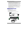
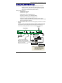
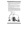
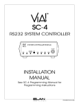
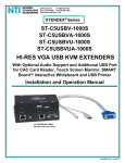
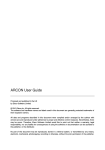
MultiVOIP™ FX
FXS-Only SIP Gateways
MVPFXS-8
MVPFXS-16
MVPFXS-24
Cabling Guide
MultiVOIP MVPFXS-8/16/24 Cabling Guide
Cabling Guide
MultiVOIP FX SIP FXS-Only Gateways
Models MVPFXS-8, MVPFXS-16, MVPFXS-24
82100110L Rev. A
Copyright
This publication may not be reproduced, in whole or in part, without prior expressed
written permission from Multi-Tech Systems, Inc. All rights reserved.
Copyright © 2006 Multi-Tech Systems, Inc.
Multi-Tech Systems, Inc. makes no representations or warranty with respect to the
contents hereof and specifically disclaims any implied warranty of merchantability or
fitness for any particular purpose. Furthermore, Multi-Tech Systems, Inc. reserves
the right to revise this publication and to make changes from time to time in the
content hereof without obligation of Multi-Tech Systems, Inc. to notify any person or
organization of such revisions or changes. Check Multi-Tech’s web site for current
versions of our product documentation.
Revision
Date
Description
A
07/17/06
Initial release.
Trademarks
Multi-Tech and the Multi-Tech logo are registered trademarks of Multi-Tech
Systems, Inc. MultiVOIP is a trademark of Multi-Tech Systems, Inc. All other brand
and product names mentioned in this publication are trademarks or registered
trademarks of their respective companies.
Patents
This Product is covered by one or more of the following U.S. Patent Numbers:
6151333, 5757801, 5682386, 5.301.274; 5.309.562; 5.355.365; 5.355.653;
5.452.289; 5.453.986. Other Patents Pending.
GENERAL CONTACT
Multi-Tech
Systems, Inc.
2205 Woodale Drive
Mounds View,
Minnesota
55112, USA
(763) 785-3500
(800) 328-9717
Fax: 763-785-9874
www.multitech.com
2
Country
France
India
Europe,
Asia,
Africa
U.S.,
Canada,
All Others
TECHNICAL SUPPORT
By E-mail
By Phone
(+33) 1-64
support@
61 09 81
multitech.fr
support@
(+91) 124multitechindia.
2340780
com
support@
(+44) 118
multitech.co.uk
959 7774
support@
multitech.com
(800) 9722439; (763)
717-5863
Multi-Tech Systems, Inc.
MultiVOIP MVPFXS-8/16/24 Cabling Guide
Introduction
This guide shows you how to set up your MultiVOIP. See the MultiVOIP User Guide
included on the MultiVOIP CD for more information.
Safety Warnings
Lithium Battery Caution
A lithium battery on the voice/fax channel board provides backup power for the
timekeeping capability. The battery has an estimated life expectancy of ten
years.
When the battery starts to weaken, the date and time may be incorrect. If the
battery fails, the board must be sent back to Multi-Tech Systems for battery
replacement.
Warning: There is danger of explosion if the battery is incorrectly
replaced.
Ethernet Ports Caution
Caution: The Ethernet ports and command ports are not designed to
be connected to a Public Telecommunictaion network.
Safety Warnings Telecom
• Use this product only with UL- and CUL-listed computers (US).
• Never install phone wiring during a lightning storm.
• Never install a phone jack in a wet location unless the jack is specifically
•
•
•
•
•
•
designed for wet locations.
Never touch uninsulated phone wires or terminals unless the phone line has
been disconnected at the network interface.
Use caution when installing or modifying phone lines.
Avoid using a phone during an electrical storm; there is a risk of electrical
shock from lightning.
Do not use a phone in the vicinity of a gas leak.
To reduce the risk of fire, use only 26 AWG or larger telephone line cord.
This product must be disconnected from power source and telephone
network interface when servicing.
Safety Recommendations for Rack Instructions
• Ensure proper installation of the MultiVOIP in a closed or multi-unit
•
enclosure by following the recommended installation as defined by the
enclosure manufacturer. Do not place the MultiVOIP directly on top of other
equipment or place other equipment directly on top of the MultiVOIP.
If installing the MultiVOIP in a closed or multi-unit enclosure, ensure
adequate airflow within the rack so that the maximum recommended
ambient temperature is not exceeded.
Multi-Tech Systems, Inc.
3
MultiVOIP MVPFXS-8/16/24 Cabling Guide
•
•
•
•
•
•
Ensure that the MultiVOIP is properly connected to earth ground via a
grounded power cord. If a power strip is used, ensure that the power strip
provides adequate grounding of the attached apparatus.
Ensure that the mains supply circuit is capable of handling the load of the
MultiVOIP. Refer to the power label on the equipment for load requirements.
Maximum ambient temperature for the MultiVOIP is 60 degrees Celsius
(140° F) at 20-90%s non-condensing relative humidity.
This equipment should only be installed by properly qualified service personnel.
Only connect like circuits. In other words, connect SELV (Secondary Extra
Low Voltage) circuits to SELV circuits and TN (Telecommunications
Network) circuits to TN circuits.
To reduce the risk of shock, all access doors should be closed during
normal operation of the equipment.
MultiVOIP Package Contents
•
•
•
•
•
•
One MultiVOIP MVPFXS unit
One power cord
One Console Cable (RJ45 to DB9 connectors)
Two rack mount brackets and four mounting screws
One printed Cabling Guide
One MultiVOIP CD containing software and user documentation.
MultiVOIPTM
Cabling
Guide
Power
Boot
4
1
WA N
LNK
FDX
S PD
2
3
4
5
6
7
8
9
10
11
12
13
14
15
16
17
18
19
20
21
22
23
24
COL
Multi-Tech Systems, Inc.
MultiVOIP MVPFXS-8/16/24 Cabling Guide
Cabling the MVPFXS-8/16/24
Prerequisites: To complete the MultiVOIP cabling procedure, you must have:
• One RJ-21 Cable. That cable must have a male end to fit the
MultiVOIP. The other end must fit your telephony equipment.
• Two common network cables (RJ45-to-RJ45).
Cabling entails connecting:
- the MultiVOIP to ground ,
- the MultiVOIP to power,
- the MultiVOIP to your LAN/WAN network,
- the control computer to your LAN/WAN network,
- the MultiVOIP to your telephone equipment, and
- connecting, optionally, the MultiVOIP Console port to the control
computer’s serial port (needed for initial setup only if your system cannot
use the voip’s default IP address).
1. Ground Connection. Be sure that the unit is properly connected to an earth
ground.
To do this, connect a grounding wire between the chassis grounding screw (see
the figure below) and a metallic object that will provide an electrical ground. In
some cases, mounting racks will can serve as an adequate earth ground.
Grounding
Screw
Cable hold-down
device is included.
T ELECO M
25
1
25
1
50
26
50
CO NSOL E
WAN
26
Voip’s Default IP
= 192.168.2.1
RJ-45
Connectors
Grounding
Cable
RJ-21
WAN/Ethernet Connection
The RJ21 50-pin connector can
terminate in either a terminal block,
a key system, or a PBX station card.
In each case, it offers FXS service
to phones or fax machines.
DB-9 Connector to
Computer Serial Port
for Console Functions
Console Port Connection
VOIP Control
through
Web GUI
Control Computer’s IP
= 192.168. 2. x
**
** Note: If network configuration makes it
difficult or impossible to assign the
control computer to 192.168.2.x,
then the voip’s IP must be reset
using the voip’s Console connection.
See User Guide for details.
Multi-Tech Systems, Inc.
5
MultiVOIP MVPFXS-8/16/24 Cabling Guide
2. Power Connection. Connect the power cord supplied with your MultiVOIP to
a live AC outlet and to the power connector on the back of the MultiVOIP.
3. VOIP-to-Network Connection. Connect a network cable (RJ45-to-RJ45) to
the WAN connector on the back of the MultiVOIP. Connect the other end of
the cable to your network. The MultiVOIP’s default IP address is
192.168.2.1.
4. Computer-to-Network Connection. Connect a network cable (RJ45-toRJ45) between your LAN/WAN network and the control computer that you
will use to configure/control the MultiVOIP. The control computer’s IP
address must be set so that the first three octets of the IP address match
those of the MultiVOIP (192.168.2.x).
5. Telephony Connection. Connect a 50-conductor cable (RJ21-to-RJ21)
between the MultiVOIP’s TELECOM receptacle and your telephone
equipment. The MultiVOIP requires a male RJ-21 connector. Secure the RJ21 connector to the TELECOM receptacle with a screw (which is typically
built into the connector) and use the hold-down device to secure the cable to
the back panel of the MultiVOIP unit. The gender of the RJ-21 connector on
the other end of the cable must fit your telephony equipment. The figure
below shows some typical ways in which the other end of the RJ-21 cable
might be connected.
to MVPFXS-8/16/24
unit
RJ-21
OR
RJ-21
OR
Terminal
Block
Key
Phone
System
RJ-21
RJ-11
PBX
Station
Card
RJ-11
RJ-11
RJ-21
The RJ-21 cable might also terminate mechanically in a punch-down block.
6
Multi-Tech Systems, Inc.
MultiVOIP MVPFXS-8/16/24 Cabling Guide
Pin-Out Information for 50-pin Connector
6. Console Connection (optional – not usually needed for initial setup). The
Console Cable is needed at initial setup only if your system cannot use the
voip’s default IP address. In that case, the Console Cable is used to change
the MultiVOIP’s IP address. Also, if, at a later date, you need to update the
MultiVOIP’s firmware, you will need to connect the Console Cable because it
is required for that process, as well.
If needed, connect the Console Cable (RJ45 male to DB9 female) between
the MultiVOIP and the control PC. Plug the RJ-45 end of the cable into the
CONSOLE port of the MultiVOIP and the DB-9 end into a serial port on
the PC.
7. Power-Up. Turn on power to the MultiVOIP by placing the ON/OFF switch
on the back panel to the ON position. Wait for the Boot LED on the
MultiVOIP to go off before proceeding. This may take a few minutes.
Proceed to the chapter “MultiVOIP and Auxiliary Software” in the User Guide.
That chapter describes how the built-in MultiVOIP software (firmware) is
accessed using a web browser and a Java program that are both up-to-date.
Best Case. If the Java and browser requirements have already been met,
and if you were able to assign the control computer to 192.168.2.x, then you
can make contact with the MultiVOIP immediately by surfing to 192.168.2.1
on the control computer.
VOIP Configuration
When the cabling connections above have been made and the command PC
has been equipped with an up-to-date web browser and Java version, then
you are ready to contact the MultiVOIP through a browser and begin
configuration. For detailed instructions about configuration, see the User
Guide on your MultiVOIP CD. The “Quick Start Guide” chapter of the User
Guide is the best place to start.
Multi-Tech Systems, Inc.
7
82100110L