1
www.conairgroup.com
USERGUIDE
UGH002/0514
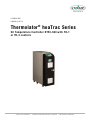
Thermolator ® heaTrac Series
Oil Temperature Controller HTR1-500 with TH-1
or TH-2 controls
Corporate Office: 724.584.5500
l Instant Access 24/7 (Parts and Service): 800.458.1960 l Parts and Service: 814.437.6861
Please record your
equipment’s model and
serial number(s) and
the date you received it
in the spaces provided.
It’s a good idea to record the model and serial number(s) of
your equipment and the date you received it in the User
Guide. Our service department uses this information, along
with the manual number, to provide help for the specific
equipment you installed.
Please keep this User Guide and all manuals, engineering
prints and parts lists together for documentation of your
equipment.
Date:
Manual Number:
UGH002/0514
Serial number(s):
Model number(s):
DISCLAIMER: Conair shall not be liable for errors contained in this
User Guide or for incidental, consequential dam-ages in connection
with the furnishing, performance or use of this information. Conair
makes no warranty of any kind with regard to this information,
including, but not limited to the implied warranties of merchantability
and fitness for a particular purpose.
Copyright 2014
Conair
All rights reserved
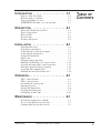
INTRODUCTION . . . . . . . . . . . . . . . . . . .1-1
Purpose of the User Guide . . . . . . . . . . . . . . . . . . . . . . . . .1-2
How the guide is organized . . . . . . . . . . . . . . . . . . . . . . . .1-2
Your responsibility as a user . . . . . . . . . . . . . . . . . . . . . . .1-2
ATTENTION: Read this so no one gets hurt . . . . . . . . . . .1-3
TABLE OF
CONTENTS
DESCRIPTION . . . . . . . . . . . . . . . . . . . .2-1
What is the Thermolator heaTrac? . . . . . . . . . . . . . . . . . . .2-2
Typical applications . . . . . . . . . . . . . . . . . . . . . . . . . . . . . .2-2
How it works: . . . . . . . . . . . . . . . . . . . . . . . . . . . . . . . . . .2-3
Specifications . . . . . . . . . . . . . . . . . . . . . . . . . . . . . . . . . .2-6
Features and options . . . . . . . . . . . . . . . . . . . . . . . . . . . . .2-8
INSTALLATION . . . . . . . . . . . . . . . . . . . .3-1
Unpacking the boxes . . . . . . . . . . . . . . . . . . . . . . . . . . . . .3-2
Preparing for installation . . . . . . . . . . . . . . . . . . . . . . . . . .3-3
Connecting the cooling water supply . . . . . . . . . . . . . . . . .3-4
Connecting the main power . . . . . . . . . . . . . . . . . . . . . . . .3-6
Testing the installation . . . . . . . . . . . . . . . . . . . . . . . . . . . .3-7
Initial setup . . . . . . . . . . . . . . . . . . . . . . . . . . . . . . . . . . . .3-8
Changing temperature units . . . . . . . . . . . . . . . . . . . . . . . .3-9
Enabling and disabling passcode protection . . . . . . . . . . .3-10
Selecting the temperature control point (TH-2 ) . . . . . . . . . .3-12
Entering setpoint deviation parameters . . . . . . . . . . . . . . .3-14
Activating SPI communication . . . . . . . . . . . . . . . . . . . . .3-15
Enabling the Auto Start feature (TH-2 ) . . . . . . . . . . . . . . .3-16
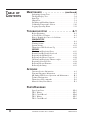
OPERATION . . . . . . . . . . . . . . . . . . . . . .4-1
TH-1 control features . . . . . . . . . . . . . . . . . . . . . . . . . . . .4-2
TH-2 control features . . . . . . . . . . . . . . . . . . . . . . . . . . . .4-3
Positioning the control panel . . . . . . . . . . . . . . . . . . . . . . .4-4
Entering passcodes . . . . . . . . . . . . . . . . . . . . . . . . . . . . . . .4-5
Starting the Thermolator . . . . . . . . . . . . . . . . . . . . . . . . . .4-6
Stopping the Thermolator . . . . . . . . . . . . . . . . . . . . . . . . .4-7
Performing an Auto Tune . . . . . . . . . . . . . . . . . . . . . . . . .4-10
MAINTENANCE . . . . . . . . . . . . . . . . . . . .5-1
Preventative maintenance schedule . . . . . . . . . . . . . . . . . . .5-2
To access the Thermolator enclosure . . . . . . . . . . . . . . . . .5-3
Checking fluid level in the reservoir . . . . . . . . . . . . . . . . .5-4
UGH002/0514
Thermolator heaTrac TH-1 and TH-2
i
TABLE OF
CONTENTS
MAINTENANCE . . . . . . . . . . . . . . .(continued)
Performing System Tests . . . . . . . . . . . . . . . . . . . . . . . . . .5-5
The Key/Display Test . . . . . . . . . . . . . . . . . . . . . . . . . . . . .5-6
Input Test . . . . . . . . . . . . . . . . . . . . . . . . . . . . . . . . . . . . . .5-7
Output Test . . . . . . . . . . . . . . . . . . . . . . . . . . . . . . . . . . . .5-8
Disabling and Enabling Outputs . . . . . . . . . . . . . . . . . . . . .5-9
Calibrating Temperature Sensors . . . . . . . . . . . . . . . . . . .5-10
Logging Operating Hours . . . . . . . . . . . . . . . . . . . . . . . .5-12
TROUBLESHOOTING . . . . . . . . . . . . . . . .6-1
Before Beginning . . . . . . . . . . . . . . . . . . . . . . . . . . . . . . . .6-2
A Few Words of Caution . . . . . . . . . . . . . . . . . . . . . . . . . .6-2
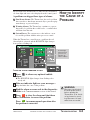
How to Identify the Cause of a Problem . . . . . . . . . . . . . . .6-3
DIAGNOSTICS
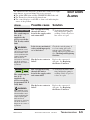
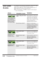
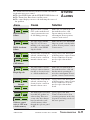
Shut Down Alarms . . . . . . . . . . . . . . . . . . . . . . . . . . . . . . .6-4
Warning Alarms . . . . . . . . . . . . . . . . . . . . . . . . . . . . . . . . .6-8
System Alarms . . . . . . . . . . . . . . . . . . . . . . . . . . . . . . . . .6-11
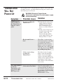
Thermolator Will Not Power Up . . . . . . . . . . . . . . . . . . .6-12
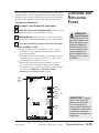
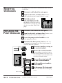
REPAIR
Checking and Replacing Fuses . . . . . . . . . . . . . . . . . . . . .6-13
Resetting and Replacing Overloads . . . . . . . . . . . . . . . . .6-14
Replacing the Motherboard . . . . . . . . . . . . . . . . . . . . . . .6-15
Replacing the Heater Contactor . . . . . . . . . . . . . . . . . . . .6-16
Checking and Replacing Thermocouples . . . . . . . . . . . . .6-17
Repairing Solenoid Valves . . . . . . . . . . . . . . . . . . . . . . . .6-18
Replacing Heater Elements . . . . . . . . . . . . . . . . . . . . . . .6-20
Removing the Pump . . . . . . . . . . . . . . . . . . . . . . . . . . . . .6-21
APPENDIX
Customer Service Information . . . . . . . . . . . . . . . . . . . . . .A-1
Warranty/Guarantee Information . . . . . . . . . . . . . . . . . . . .A-2
MP Pumps HTO Series Operation and Maintenance . . . . .B-1
Technical Information . . . . . . . . . . . . . . . . . . . . . . . . . . . .C-1
Thermolator SPI commands . . . . . . . . . . . . . . . . . . . . . . .D-1
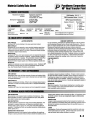
Material Safety Data Sheets . . . . . . . . . . . . . . . . . . . . . . . .E-1
PARTS/DIAGRAMS
Spare Parts Lists . . . . . . . . . . . . . . . . . . . . . . . . . . . . . . .PD-1
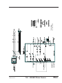
TH-1 Wiring . . . . . . . . . . . . . . . . . . . . . . . . . . . . . . . . .PD-5
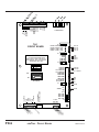
TH-1 Circuit Board . . . . . . . . . . . . . . . . . . . . . . . . . . . .PD-6
TH-1 Wiring . . . . . . . . . . . . . . . . . . . . . . . . . . . . . . . . .PD-7
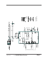
TH-2 Circuit Board . . . . . . . . . . . . . . . . . . . . . . . . . . . .PD-8
ii
Thermolator heaTrac TH-1 and TH-2
UGH002/0514
INTRODUCTION
● Purpose of the User Guide . . . .1-2
● How the guide is organized . . . .1-2
● Your responsibilities as a user .1-2
● ATTENTION: Read this so
no one gets hurt . . . . . . . . . . .1-3
UGH002/0514
Thermolator heaTrac TH-1 and TH-2
1-1
PURPOSE OF
THE USER
GUIDE
This User Guide describes the Conair Thermolator® TH-1 and
TH-2 oil temperature controllers and explains step-by-step
how to install, operate, maintain and repair this equipment.
HOW THE
GUIDE IS
ORGANIZED
Symbols have been used to help organize the User Guide and
call your attention to important information regarding safe
installation and operation.
Before installing this product, please take a few moments to
read the User Guide and review the diagrams and safety information in the instruction packet. You also should review manuals covering associated equipment in your system. This
review won’t take long, and it could save you valuable installation and operating time later.
Symbols within triangles warn of conditions that could
be hazardous to users or could damage equipment.
Read and take precautions before proceeding.
1
Numbers within shaded squares indicate tasks or steps
to be performed by the user.
◆
A diamond indicates the equipment’s response to an
action performed by the user.
❒
●
YOUR
RESPONSIBILITY
AS A USER
An open box marks items in a checklist.
A shaded circle marks items in a list.
You must be familiar with all safety procedures concerning
installation, operation and maintenance of this equipment.
Responsible safety procedures include:
● Thorough review of this User Guide, paying particular
attention to hazard warnings, appendices and related diagrams.
● Thorough review of the equipment itself, with careful
attention to voltage requirements, intended uses and
warning labels.
● Thorough review of instruction manuals for associated
equipment.
● Step-by-step adherence to instructions outlined in this
User Guide.
1-2
INTRODUCTION
Thermolator heaTrac TH-1 and TH-2 control
UGH002/0514
We design equipment with the user’s safety in mind. You can
avoid the potential hazards identified on this machine by
following the procedures outlined below and elsewhere in the
User Guide.
ATTENTION:
READ THIS
SO NO
ONE GETS HURT
WARNING: Improper installation,
operation or servicing may result in
equipment damage or personal injury.
This equipment should be installed, adjusted,
and serviced by qualified technical personnel
who are familiar with the construction, operation and potential hazards of this type of equipment.
All wiring, disconnects and fuses should be
installed by qualified electrical technicians in
accordance with electrical codes in your region.
Always maintain a safe ground. A properly
sized conductive ground wire from the incoming
power supply must be connected to the chassis
ground terminal inside the electrical enclosure.
Improper grounding can result in personal
injury and erratic machine operation.
Do not operate the equipment at power levels
other than what is specified on the the equipment serial tag and data plate.
WARNING: Electrical shock hazard
This equipment is powered by three-phase
main voltage, as specified on the machine serial tag and data plate.
Always disconnect and lock out the incoming
main power source before opening the electrical enclosure or performing non-standard operating procedures, such as troubleshooting or
maintenance. Only qualified personnel should
perform procedures that require access to the
electrical enclosure while power is on.
CAUTION: Hot surfaces
Surface temperatures inside the Thermolator
can exceed 500° F (260° C). Always allow the
unit to cool to below 100° F (38° C) before
opening, servicing or disassembling the unit.
UGH002/0514
Thermolator heaTrac TH-1 and TH-2 control
INTRODUCTION
1-3
ATTENTION:
WARNING: Hazardous substance
READ THIS
The electrical contactors in the
Thermolator have mercury contactors.
Mercury is considered a hazardous substance and must be dealt with accordingly. Material Safety Data Sheet (#743997) has been included in the instruction
packet. This sheet explains the potential
hazards, how to avoid them and how to
clean up and dispose of the mercury if it
spills.
SO NO
ONE GETS HURT
1-4
INTRODUCTION
Thermolator TH-1 and TH-2
UGH001/0514
DESCRIPTION
● What is the Thermolator
heaTrac? . . . . . . . . . . . . . . . . .2-2
● Typical applications . . . . . . . . . .2-2
● How it works . . . . . . . . . . . . . . .2-5
● Specifications: heaTrac . . . . . . .2-6
● Features and options . . . . . . . . .2-8
UGH002/0514
Thermolator heaTrac TH-1 and TH-2
2-1
WHAT IS THE
THERMOLATOR
HEATRAC?
The Thermolator heaTrac circulates oil at a temperature to add
or remove heat as needed to maintain a uniform temperature
setpoint in the process. The heaTrac offers an enhanced TH-2
control, with additional diagnostic features and autostart capabilities.
Both the TH-1 and TH-2 models are available in single or
multiple-zone configurations. Multiple-zone models can control up to two temperatures at different locations in the
process. Two- zone models have common cooling water manifolds and electrical connections.
The best model for your application depends on the process
temperature you need to maintain and the quality of the cooling water supply.
TYPICAL
APPLICATIONS
2-2
DESCRIPTION
TH-1 and TH-2 models separate the cooling water from the
process fluid, which is held in a reservoir. All heaTrac models
are recommended for:
● Process temperatures up to 500°F (260°C).
● Use with chiller water, or with properly treated and filtered
tower or city water..
Thermolator heaTrac TH-1 and TH-2 control
UGH002/0514
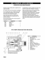
Thermolator heaTrac models maintain the process temperature by heating and cooling fluid for the process circuit. The
process fluid (heat transfer oil), which is stored in a reservoir,
is isolated from the optional cooling water supplied by a
chiller, tower or other source
1
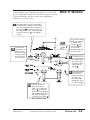
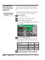
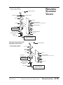
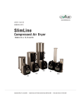
HOW IT WORKS:
The temperature of the process fluid is
measured as it leaves the unit’s heater
tank. The fluid then flows through the “To
Process” line A to the mold or process.
The fluid returns to the unit through the
“From Process” line B for reheating or
cooling.
G
3b
If the process
temperature is
below the setpoint, the heater
elements inside
the heater tank
are energized.
A
E
The vent line allows
warm process fluid
to expand to the
reservoir G . The
reservoir supplies
process fluid
through a make-up
line as needed.
4
C
2
B
OPTIONAL
3a
The pump moves
process fluid from
the mixing tank to
the heater tank.
Pressure is measured after the
pump E..
The temperature
of the process
fluid is measured
as it flows into
the suction tank
through the “From
Process” line B .
If the temperature is
above the setpoint
value, the cooling valve
opens. C Cool water
enters the cooling piping
and circulates through a
tube heat exchanger to
cool the process fluid. B
Note: cooling is optional.
UGH002/0514
Thermolator heaTrac TH-1 and TH-2 control
DESCRIPTION
2-3
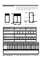
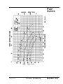
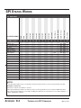
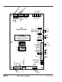
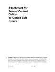
Dimensions and performance characteristics vary according to
the model, voltage and components selected. See the cabinet
style reference chart to determine dimensional information for
your specific model. Additional technical information can be
found in the Appendix of this User Guide.
SPECIFICATIONS
A
B
HTR1-500 (single zone)
HTR2-500 (dual zone)
MODELS
Performance Characteristics
Minimum setpoint °F {°C}
Maximum setpoint °F {°C}
Pump Performance
Pump Size Hp {kW}
1 {0.75}
Nominal flow gpm {l/min}
55 {208}
Pressure @ nominal flow psi {bar}
16 {1.1}
Dimensions inches {mm}
A -Height
B- Width
C- Depth
Weight Ib {kg}
Operating
300 {136}
Shipping
470 {213}
Water Connections NPT inches (Female)
To/From Process
Cooling Water Inlet/Outlet *
HTR1-500 rear view and connections
HTR1-500
HTR2-500
70 {21}
500 {260}
70 {21}
500 {260}
1.5 {1.12} 2 {1.49}
65 {246} 75 {284}
21 {1.5} 24 {1.7}
3 {2.24}
85 {322}
32 {2.2}
1 {0.75} 1.5 {1.12} 2 {1.49} 3 {2.24}
55 {208} 65 {246} 75 {284} 85 {322}
16 {1.1} 21 {1.5} 24 {1.7} 32 {2.2}
43 {1090}
14 {355}
31.5 {800}
43 {1090}
28 {710}
31.5 {800}
305 {138} 310 {141} 320 {145} 600 {272} 610 {277} 620 {281} 640 {290}
475 {216} 480 {218} 490 {222} 770 {349} 780 {354} 790 {358} 810 {367}
1.25
0.75
1.25
0.75
FULL LOAD AMPS †
HTR1-500
HTR2-500
Heater
6 kW
12 kW
18 kW
6 kW
12 kW
18 kW
Voltage
208V 230V 460V 575V 208V 230V 460V 575V 208V 230V 460V 575V 208V 230V 460V 575V 208V 230V 460V 575V 208V 230V 460V 575V
Pump
1 Hp
1.5 Hp
2 Hp
3 Hp
{0.75 kW}
{1.12 kW}
{1.49 kW}
{2.24 kW}
21.2
21.9
23.6
26.5
19.2
19.8
21.4
24.0
9.6
9.9
10.7
12
7.7
7.9
8.6
9.6
37.8
38.5
40.2
43.1
34.2
34.8
36.4
39.0
17.1
17.4
18.2
19.5
21.4
13.9
14.6
15.6
54.4
55.0
56.8
59.7
49.2
49.8
51.4
54.0
24.6
24.9
25.7
27.0
19.7
19.9
20.6
21.6
42.2
43.5
47.1
52.8
38.2
39.4
42.6
47.8
19.1
19.7
21.3
23.9
15.3
15.8
17.0
19.1
75.6
76.9
80.4
86.2
68.4
69.6
72.8
78.0
34.2
34.8
36.4
39.0
15.3
15.8
17.0
19.1
109.0 98.6
110.3 99.8
113.8 103.0
119.3 108.0
49.3
49.9
51.5
54.1
39.4
39.9
41.2
43.2
SPECIFICATIONS NOTES:
* For units equipped with optional heat exchanger and cooling circuits.
†All voltages are 3 phase, 60 Hz.
Specifications can change without notice. Check with a Conair representative for the most current information.
2-4
DESCRIPTION
Thermolator heaTrac TH-1 and TH-2 control
UGH002/0514
INSTALLATION
● Unpacking the boxes . . . . . . . . .3-2
● Preparing for installation . . . . . .3-3
● Connecting the water supply . .3-4
● Optional purge valve hookups .3-5
● Connecting the main power . . .3-6
● Testing the installation . . . . . . . .3-7
● Initial setup . . . . . . . . . . . . . . . .3-8
● Changing temperature units . . .3-9
● Enabling and disabling
passcode protection . . . . . . .3-10
● Selecting the temperature
control point (TH-2 ) . . . . . . . . .3-12
● Entering setpoint
deviation parameters . . . . . . .3-14
● Activating SPI
communication . . . . . . . . . . . .3-15
● Installing the Auto Start
feature . . . . . . . . . . . . . . . . . .3-16
UGH002/0514
Thermolator heaTrac TH-1 and TH-2
3-1
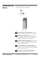
UNPACKING THE
BOXES
Thermolator heaTrac models come fully assembled. If they
were specified at the time of the order, the optional cooling
exchanger and valve is factory-installed.
Remote control cord
(TH-2 only)
Thermolator heaTrac
3-2
INSTALLATION
1
Carefully remove the Thermolator and compo-
2
Remove all packing material, protective paper,
tape, and plastic. Check inside the electrical enclosure
and behind the side panels for accessories or hardware
that may have been placed there for shipping.
3
Carefully inspect all components to make sure no
4
Take a moment to record serial numbers and
specifications in the blanks provided on the back of the
User Guide’s title page. The information will be helpful if
you ever need service or parts.
5
You are now ready to begin installation.
nents from their shipping containers, and set upright.
damage occurred during shipping, and that you have all
the necessary hardware. If damage is found, notify the
freight company immediately.
Complete the preparation steps on the next page.
Thermolator heaTrac TH-1 and TH-2 control
UGH002/0514
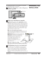
The Thermolator heaTrac is easy to install, if you plan the
location and prepare the area properly.
1
Position the Thermolator as close to the process
machine as possible.
PREPARING FOR
INSTALLATION
Thermolator
Process machine
Alternate
locations
2
Make sure the installation area provides:
❒ A three-phase power source supplying the correct
current for your Thermolator model. Check the serial tag
on the side of the electrical enclosure for the required voltage, phase, frequency, full load amps, disconnect fuse size
and minimum wire connection size. Field wiring should be
completed by qualified personnel to the planned location
for the Thermolator. All electrical wiring should comply
with your region’s electrical codes.
❒ A clean, well-ventilated environment.
The room temperature should not exceed 120° F (48° C)
with 95% non-condensing humidity and should not fall
below 32° F (0° C).
❒ Minimum clearance for safe operation and
maintenance. The diagram at right shows
minimum clearance for operation. You also
need enough clearance in the rear for
water hookups. For maintenance, you
should move the Thermolator to
12 inches
provide at least 36 inches on any side
(305 mm)
of the Thermolator.
20 inches
(508 mm)
❒ A source of water for cooling.
City, tower or chiller water may be used, as long as the
supply pressure is at least 15 psi and not more than 85 psi.
3
10 inches
(254 mm)
12 inches
(305 mm)
Install plumbing for process and cooling lines.
You will need two 11/4-inch NPT male fittings for the
process oil inlet and outlet and two 3/4-inch NPT male
fittings for the cooling water inlet and outlet. Larger line
sizes are acceptable as long as they are reduced at the
Thermolator connections. Smaller line sizes are not recommended.
UGH002/0514
Thermolator heaTrac TH-1 and TH-2 control
INSTALLATION
3-3
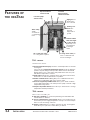
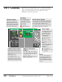
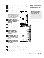
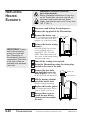
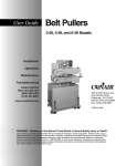
FEATURES OF
THE HEATRAC
Expansion/Fluid
reservoir tank
Low-watt
density electric
immersion heater
Low level pump
shutoff safety
TEFC Pump
Totally
enclosed fan
cooled pump
motor
Sight glass for
visual inspection of oil level
Venting solenoid valve
prevents
trapped air in
system.
Shell and tube
heat exchanger
cooling circuit
(optional) cools
the unit before
powering it
down.
Air-cooled seal cavity
no cooling water required
TH-1
Cooling check valve prevents coolant back flow
into the exchanger.
CONTROL
Standard features include:
● Actual temperature display shows the actual temperature of the fluid
entering the
to-process line. ● Setpoint temperature display shows the fluid temperature setpoint during normal operation. Both of these window will
display alarms, error codes modes and parameters if there is a problem with the temperature controller.
● Status lights indicate the operating status of the device. Green when
the device is on and red when there is a problem.
● RS485 communications utilizing SPI protocol with baud rates and
addresses programmable right on the operator panel.
● Visual and (optional) audible alarms alerts you to alarm conditions
such as high/low deviation, low water pressure, pump overload or high
temperature safety switch.
● Setpoint adjustment buttons Press the up or down arrows to change
temperature and SPI parameters.
TH-2
CONTROL
All the features of the TH-1 plus:
● Autostart capability for convenient preheating of molds. Works with
external timers or switches.
● Choice of temperature control points allows you to monitor and control from the process supply temperature or the process return temperatures or from an average of the two.
● Remote control with 15 foot cables, optional to 50 feet, and magnetic
backs allow you to place the control where you want it.
3-4
INSTALLATION
Thermolator heaTrac TH-1 and TH-2 control
UGH002/0514
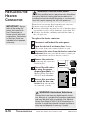
The Thermolator process inlets and outlets must be connected
to the plumbing that will circulate the temperature-controlled
water or fluid through the process. Optional cooling water
inlets and outlets are connected to the cooling water supply.
1
Remove the shipping pipe plug from the female
connections on the back of the Thermolator.
2
Install pipe to the rear of the Thermolator.
3
Coat the pipe threads with thread sealant.
4
Connect the male pipe to the appropriate
female connection on the back of the unit. Start
Use male 11/4-inch NPT piping for process oil connections and male 3/4 inch NPT piping for water connections.
Pipe and pipe threads must be clean and new. Clean
threads with solvent, removing all oil, grease and dirt.
Allow the threads to dry before proceeding.
CONNECTING
PROCESS OIL
AND COOLING
WATER SUPPLY
LINES
Follow the sealant manufacturer’s directions.
by hand until the threads engage, then use a pipe wrench
to tighten the connection only enough to prevent leaks.
Do not over-tighten!
Tools for installation:
❒ Pipe wrench large enough
for a 2-inch pipe
❒ Premium quality Teflon
thread sealant rated for
500Þ F oil.
NOTE: We recommend
that you install an
external ball valve on
the cooling water inlet
of the Thermolator. This
valve is useful for service when cooling
option is installed.
UGH002/0514
Thermolator heaTrac TH-1 and TH-2 control
INSTALLATION
3-5
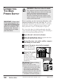
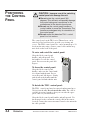
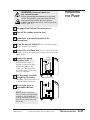
CONNECTING
THE MAIN
POWER SUPPLY
IMPORTANT: Always refer
to the wiring diagrams that
came with your temperature
control unit before making
electrical connections. The
diagrams show the most
accurate electrical component information.
WARNING: Electrical shock hazard
This equipment is powered by three-phase main
voltage. Always disconnect and lock out the main
power source before performing any work
involving electrical connections. All wiring,
disconnects and fusing should conform to your
region’s electrical codes and should be installed
only by qualified personnel.
Before beginning, note the electrical specifications on the
nameplate mounted to the side of the unit. The electrical
hookup must match these specifications with +/- 10% maximum voltage variance. An improper power supply could
damage the unit as well as seriously injure an operator.
The electrical hookup also should run through a fused disconnect sized for the nameplate amperage and conforming to
Article 250 of the National Electrical Code.
1
Open the unit’s electrical enclosure.
2
Insert the main power wire through the knockout
hole in the right side of the enclosure.
3
Secure the power wire with a rubber compression fitting or strain relief.
4
Connect the power wires to the terminals.
5
Connect the ground
wire to the copper
Connect the three hot
wires to L1, L2, and L3
on the terminal block.
grounding mount.
If you have installed a
disconnect device, follow
the manufacturer’s wiring
instructions.
IMPORTANT! Before initiating
power to the unit:
❒ Check the system for leaks.
❒ Verify that the disconnect fuse and
minimum wire size meet the voltage,
phase,frequency, and amperage
specifications stated on the nameplate mounted on the side of the unit.
❒ Verify that resistance to ground on
each phase is at least 1 meg ohm.
3-6
INSTALLATION
Thermolator heaTrac TH-1 and TH-2 control
UGH002/0514
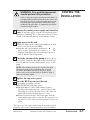
WARNING: Only qualified personnel
should perform this procedure.
Parts of this test require opening the unit while it is
energized. Only qualified personnel who have been
trained in the use of electrical testing devices and
in avoiding the safety hazards involved in safely
troubleshooting this type of equipment should perform this test procedure.
1
TESTING THE
INSTALLATION
Turn on the cooling water supply and check for
leaks. If any leaks appear, stop the test and fix the problem before continuing. The cooling water must be at least
15 PSI or the unit will function slowly during cooling.
2
3
Apply power to the unit.
◆ Indicator lights on the control panel blink green, then
red, to test operation of the LEDs.
◆ Setpoint and actual windows will display
for
three seconds, followed by the software version. The
windows then display the factory default setpoint of
100° F and the actual temperature.
Check the rotation of the pump. Remove the top
access panel. Verify that the pump rotation matches the
direction indicated on the rotation sticker on top of the
pump.
NOTE: If the rotation is incorrect, stop the test and
disconnect power to the unit. Open the electrical
enclosure and switch any two of the three power
source wires on the terminal block. Return to Step 2
and check rotation again.
4
5
Replace the top access panel.
Press the RUN key to start the unit.
If everything is working correctly:
◆ The RUN/STOP light turns green.
◆ The unit initiates a 60-second venting sequence.
Cooling and venting valves are active for 60 seconds.
The pump is active for the final 30 seconds. Indicator
lights will energize when the device is active.
◆ Normal operation begins. The heater turns on if the
actual temperature is below setpoint. The optional cooling valve is active if the actual temperature is above setpoint.
The test is over. Proceed to initial setup if the unit operated
normally; refer to the TROUBLESHOOTING section if it did not.
UGH002/0514
Thermolator heaTrac TH-1 and TH-2 control
INSTALLATION
3-7
INITIAL SETUP
WARNING: Electric shock hazard
This equipment is powered by high voltage. Always
disconnect and lock out the main power source
before opening the unit or the electrical enclosure to
modify factory settings. Failure to disconnect and
lock out the main power source can result in severe
personal injury.
The factory-set parameters and operating modes will satisfy
most applications. But you can change some settings and
enable or disable features as needed.
You can modify the parameters for high and low process temperature deviation warnings from the control panel. See
SETTING SETPOINT DEVIATION PARAMETERS.
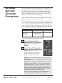
Dip switches on the motherboard inside the TH-1 and TH-2
electrical enclosure allow you to:
❒ Select the units of measure for temperature displays.
❒ Enable password protection.
❒ Enable the Auto Tune.
❒ Enable the Auto Start feature.
❒ Enable the Test Mode.
❒ Select the source point of temperature control.
8 7 6 5 4 3 2 1
Dip switch Configuration
No.
1
2
3
4*
5*
6
7†
8†
OFF
Display units in °F
Auto Tune disabled
Passcode protect
Auto Start disabled
Control point protect
Test Mode disabled
Controller type selection
Controller type selection
ON
Display units °C
Auto Tune enabled
Password reset/modify
Auto Start enabled
Control point source select
Test mode enabled
Controller type selection
Controller type selection
* Available only on TH-2 models.
† Switch 7 must be off and 8 must be ON for heaTrac oil units.
not change these settings.
To change the dip switch settings, see the appropriate topic
on the following pages.
3-8
INSTALLATION
Thermolator TH-1 and TH-2
UGH002/0514
WARNING: Electric shock hazard
This equipment is powered by high voltage. Always
disconnect and lock out the main power source
before opening the unit or the electrical enclosure to
modify factory settings. Failure to disconnect and
lock out the main power source can result in severe
personal injury.
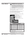
CHANGING
TEMPERATURE
UNITS
The temperature units are factory-set as degrees Celsius or
degrees Fahrenheit, as specified when the unit was ordered.
When the Thermolator is on, the indicator lights to the right
of the Actual temperature display on the control panel will
show which temperature unit has been set.
To change this setting, move Dip Switch 1 on the control
circuit board.
1
2
3
Disconnect and lock out main power to the
Thermolator.
Open the electrical enclosure.
Change Dip Switch 1 to:
OFF for °F
8 7 6 5 4 3 2 1
4
ON for °C
8 7 6 5 4 3 2 1
NOTE: All dip switch illustrations in this manual show
switches 7 OFF and 8 set
to ON. Do Not Change
these settings.
Close the electrical enclosure and restore main
power to begin operating.
UGH002/0514
Thermolator TH-1 and TH-2
INSTALLATION
3-9
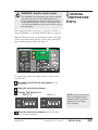
ENABLING AND
DISABLING
PASSCODE
PROTECTION
WARNING: Electric shock hazard
This equipment is powered by high voltage. Always
disconnect and lock out the main power source
before opening the unit or the electrical enclosure to
modify factory settings. Failure to disconnect and
lock out the main power source can result in severe
personal injury.
The TH-1 and TH-2 provide the ability to protect system
parameters from unauthorized changes during normal operating mode. When system passcode protection is enabled, the
following parameters cannot be changed unless you enter the
correct passcode:
● The Process Setpoint
● High Deviation Alarm Setpoint
● Low Deviation Alarm Setpoint
● Baud Rate selection for serial communications
● Address selection for serial communications
When the unit is turned on for the first time, passcode protection is disabled. To enable passcode protection:
NOTE: All dip switch illustrations in this manual show
switches 7 OFF and 8 set
to ON. Do Not Change
these settings.
3-10
INSTALLATION
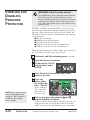
1
Disconnect and lock out main power to the unit.
2
3
Open the electrical enclosure.
4
Close the electrical enclosure and restore
power to the unit.
5
Press any
button when
the control displays “Pas rSt”
(Passcode Reset).
Set dip switch 3 to ON
and switches 5 and 6
to OFF.
8 7 6 5 4 3 2 1
The control will
display the last
passcode used.
6
Select a new passcode using the ▲ and ▼
setpoint adjustment buttons.
Stop pressing the setpoint buttons when the passcode you
want appears in the setpoint display window. Selecting
“OFF” as the passcode will disable the passcode feature.
Thermolator heaTrac TH-1 and TH-2 control
UGH002/0514
ENABLING AND
DISABLING
PASSCODE
PROTECTION
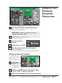
7
Press the RUN button to save the passcode.
◆ The control will display “Pr OFF” to prompt you to
remove power to the unit.
IMPORTANT: If RUN is not pressed, the new
passcode will not be saved.
8
Turn off power to the unit. Disconnect and lock out
9
Open the electrical
enclosure.
the main power supply.
8 7 6 5 4 3 2 1
10 Set dip switch 3 to OFF.
the electrical enclosure and restore
11 Close
power to the unit.
A passcode now is required to change system parameters.
Disabling Passcode Protection
To disable passcode
protection and allow
universal access to
system parameters:
1
Follow Steps 1
through 5 in the
previous section
on enabling passcode protection.
2
3
Hold down the ▼ setpoint adjustment button
to select “OFF” as the new passcode.
Follow steps 7 through 11 in the previous section.
UGH002/0514
Thermolator heaTrac TH-1 and TH-2 control
INSTALLATION
3-11
SELECTING THE
TEMPERATURE
CONTROL POINT
(TH-2
WARNING: Electric shock hazard
This equipment is powered by high voltage. Always
disconnect and lock out the main power source
before opening the unit or the electrical enclosure to
modify factory settings. Failure to disconnect and
lock out the main power source can result in severe
personal injury.
ONLY)
MaxTrac models control the process temperature based upon
the average of the temperatures recorded at the supply (to
process) and return (from process) thermocouples.
TH-2 models allow you to select how the unit will measure
and control the process temperature. The control point can be
selected as the supply, the return or the average of the the two
temperatures.
To select the control point source on TH-2 models:
NOTE: All dip switch illustrations in this manual show
switches 7 and 8 set to ON.
If you have an Isolated
Circuit model, these switches should be set to OFF.
3-12
INSTALLATION
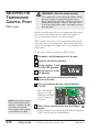
1
Disconnect and lockout power to the unit.
2
3
Open the electrical enclosure.
4
Set dip switch 5 to the
ON position.
5
Close the electrical enclosure and restore
power to the unit.
6
Press any button when the control displays
“Cnt Pt”.
Set dip switches 3 and
6 to the OFF position.
8 7 6 5 4 3 2 1
The controller will
display “Sel CnP”
and flashes the LED
for the current control point.
7
Select a new control point using the Display
button.
Stop pressing the select button until the indicator light next
to the control point you want illuminates.
Thermolator heaTrac TH-1 and TH-2 control
UGH002/0514
SELECTING THE
TEMPERATURE
CONTROL POINT
(TH-2
8
ONLY)
Press the RUN button to save the control point.
◆ The control will display “Pr OFF” to prompt you to
remove power to the unit.
IMPORTANT: If RUN is not pressed, the new
control point source will not be saved.
9
10
Turn off power to the unit. Disconnect and lock out
the main power supply.
Open the electrical
enclosure.
8 7 6 5 4 3 2 1
11 Set dip switch 5 to
OFF.
12 Close the electrical enclosure and restore
power to the unit.
The TH-2 will now control the process temperature based
on actual temperatures recorded at the new control point
source.
UGH002/0514
Thermolator heaTrac TH-1 and TH-2 control
INSTALLATION
3-13
ENTERING
SETPOINT
DEVIATION
PARAMETERS
You can establish a normal operating range around the process
temperature setpoint using the high and low deviation parameters. If the process temperature exceeds the high deviation
limit, or falls below the low deviation limit for longer than 15
minutes, the Thermolator will alert you to the unacceptable
temperature variation with an alarm light.
These temperature deviation limits will adjust automatically
relative to the process temperature setpoint.
The factory default setting is the process temperature setpoint
± 25° F (4° C). This parameter is adjustable to establish a narrower or wider acceptable temperature range for normal operation. The Low Deviation cannot be set to fall below the factory-set Low Safety temperature. The High Deviation cannot be
set to exceed the factory-set High Safety temperature.
FACTORY DEFAULT SETTINGS
Model
HTR1-500
Process Setpoint
100° F (38° C)
High Safety
510° F (266° C)
Low Safety
60° F (16° C)
To change the temperature deviation settings:
1
Press the Setpoint Select
button to select the deviation
parameter you want to
change.
2
Use the ▲ and ▼ setpoint
buttons to enter the deviation
temperature. The setting is
stored in memory even when the
power is turned off. The recommended setting is ± 2-10° F.
NOTE: If you enabled passcode protection, you must
enter the passcode to change this parameter. Too enter
the passcode:
Hold down the Setpoint Select button for 5 seconds.
When the control displays “ 1 PaS”, use the setpoint
adjustment buttons to enter the passcode. Press the
Setpoint Select button again. If the correct passcode
was entered the controller will display ACC PAS for 3
seconds. If the passcode was incorrect, the controller
will display rEJ PAS (rejected passcode).
Access to system parameters remain until power is
cycled or the RUN or STOP button is pressed.
3-14
INSTALLATION
Thermolator heaTrac TH-1 and TH-2 control
UGH002/0514
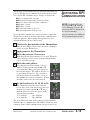
The heaTrac series Thermolators provide SPI compatible support for RS-485 serial communications with a host machine.
You can use SPI communication to change or monitor the:
● Process temperature setpoint
● High and low temperature deviation alarms
● Process status (run and alarm conditions)
● Machine 1 status
● Machine 2 status
● Actual temperature to process
● Actual temperature from process
To use the SPI communication option, you must connect the
Thermolator to the host machine and set the communication
baud rate and node address using the setpoint select and
adjustment buttons on the control panel.
1
Connect the host machine to the Thermolator.
2
3
Apply power to the Thermolator.
Enter the passcode, if necessary.
4
Enter the node address.
5
ACTIVATING SPI
COMMUNICATION
NOTE: To disable SPI, use
the setpoint ▲ or ▼ arrow to
select Address. Press the ▼
arrow until OFF is displayed in
the setpoint window.
See the APPENDIX for additional
SPI programming information.
Plug the male DB9 connector into the serial communications port on the Thermolator.
Hold the Setpoint Select button for 5 seconds. When the
control displays 1 PaS, use the setpoint adjustment buttons to enter the passcode.
Press the Setpoint Select button to choose
Address. Then press the setpoint ▲ or ▼
arrow until the address you want appears in
the setpoint display. The address may be set
to any number from 32 to 254 (a hexadecimal integer between 20 and FE), as long as
that number has not been assigned to another
machine connected to the same network.
Set the baud rate to 12, 24, 48 or 96.
The Thermolator must be set to send and
receive data at the same baud rate as the host
machine. Press the setpoint ▲ or ▼ arrow
until the baud rate you want appears in the
setpoint display window.
12 = 1200 bps
48 = 4800 bps
24 = 2400 bps
96 = 9600 bps
The green SPI status light on the control panel should flash
when the unit is communicating. The LED will turn red, indicating an alarm, if SPI communication is not properly set up.
UGH002/0514
Thermolator heaTrac TH-1 and TH-2 control
INSTALLATION
3-15
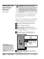
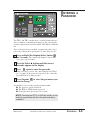
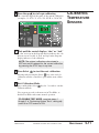
INSTALLING THE
AUTO START
FEATURE
WARNING: Electric shock hazard
This equipment is powered by high voltage. Always
disconnect and lock out the main power source
before opening the unit or the electrical enclosure to
modify factory settings. Failure to disconnect and
lock out the main power source can result in severe
personal injury.
(TH-2 ONLY)
If you have a TH-2 model, you can automatically start and
stop the Thermolator from a remote switching or timing
device that has power contacts rated 110VAC, such as the
process machine control.
Wiring the device to the Thermolator is accomplished through
a dry contact to the appropriate terminals on the motherboard.
After wiring the device to the unit, Auto Start must be
enabled by configuring a dip switch on the motherboard.
1
2
3
Disconnect and lockout power to the unit.
Open the electrical enclosure.
Punch a small hole in the left side of the
electrical enclosure. The hole must be large enough to
accommodate conduit for the power contact wires from
your switching or timing device.
4
Insert the two power leads from the device
through the conduit into the electrical enclosure.
Always
refer to the wiring diagrams
that came with your temperature control unit before making electrical connections. The
diagrams show the most
accurate electrical component
information.
5
4
3
2
1
OPS
OPS
FSTAT
FSTAT
LLS/WPS
LLS/WPS
AUTOSTART
AUTOSTART
HPS/LPS
HPS/LPS
IMPORTANT:
F1
AC IN
4
AC IN + 3
AC OUT
2
AC OUT + 1
6
5
4
3
2
1
Device contacts
Connect the 110VAC device contact wires to
the Auto Start terminals. Make sure terminals are
screwed tight.
3-16
INSTALLATION
Thermolator heaTrac TH-1 and TH-2 control
UGH002/0514
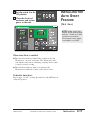
6
Set dip switch 4 to the
ON position.
7
Close the electrical
enclosure and restore
power to the unit.
8 7 6 5 4 3 2 1
INSTALLING THE
AUTO START
FEATURE
(TH-2 ONLY)
NOTE: All dip switch illustrations in this manual show
switches 7 and 8 set to ON.
If you have an Isolated
Circuit model, these switches should be set to OFF.
When Auto Start is enabled:
◆ The Auto Start indicator light flashes to indicate that the
Thermolator can start at any time. The Thermolator will
start whenever the remote switching or timing device sends
a signal to start processing.
◆ The Auto Start indicator light is on whenever the
Thermolator is under the control of the remote device.
To disable Auto Start:
Repeat steps 1,2 and 7, setting dip switch 4 to the OFF instead
of the ON position.
UGH002/0514
Thermolator heaTrac TH-1 and TH-2 control
INSTALLATION
3-17
OPERATION
● TH-1 control . . . . . . . . . . . . . . . .4-2
● TH-2 control . . . . . . . . . . . . . . . .4-3
● Positioning the control panel . .4-4
● Entering a passcode . . . . . . . . .4-5
● Starting the Thermolator . . . . . .4-6
● Stopping the Thermolator . . . . .4-7
● Performing an Auto Tune . . . . . .4-8
UGH002/0514
Thermolator heaTrac TH-1 and TH-2
4-1
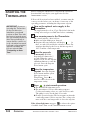
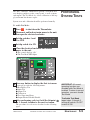
TH-1 CONTROL
All normal operating functions can be controlled from the
TH-1 control panel. If you have the optional manual mold
purge, the control button is located on the side of the
Thermolator electrical enclosure.
Run/Stop
Setpoint display
The window displays the
setpoints entered for the
fluid temperature, the high
and low temperature deviation alarms, the SPI baud
rate and the SPI address.
Press the RUN button to
start normal operation.
Press STOP to stop the
temperature control unit.
= Running
= Stopped
= Alarm (flashing)
Actual values display
The green window displays the temperature
at the middle of the mold. This temperature
is calculated as an average of the temperatures of the supply oil and return oil.
The lights indicate whether the temperature
is in degrees Fahrenheit or Celsius.
Status lights
The lights indicate the
operating status of the
listed components.
Except in Test Mode
and Auto Start, the
lights indicate:
= Off or inactive
= On or active
= Alarm condition
Setpoint Select button
Press repeatedly until a green
light appears next to the parameter you want to program or view.
NOTE: Default settings for the deviation setpoints are:
High = setpoint + 10Þ F
Low = setpoint - 10Þ F
A warning alarm occurs (indicator
light turns red) whenever the actual
temperature is outside this setpoint
range. Recommend setting: ± 2-10Þ.
4-2
OPERATION
Test Mode is used for
initial
programming. When test
mode is enabled, normal operation is
disabled.
= Test Mode off
= Test Mode on; unit
disabled
Setpoint adjustment
buttons
Press ▲ or ▼ to enter temperature and SPI parameters. Press ▲
to increase a value. Press ▼ to
decrease a value.
TIP: Press and hold the button for
faster scrolling speed.
Alarm
Press to acknowledge the
alarm light and silence the
optional audible alarm. The
alarm light will flash until the
cause of the alarm condition
is fixed.
Thermolator heaTrac TH-1 and TH-2 control
UGH002/0514
All normal operating functions can be controlled from the
TH-2 control panel, including the optional mold purge.
TH-2 CONTROL
Run/Stop
Setpoint display
The window displays the
setpoints entered for the
fluid temperature, the high
and low temperature deviation alarms, the SPI baud
rate and the SPI address.
Press the RUN button to
start normal operation.
Press STOP to stop the
temperature control unit.
= Running
= Stopped
= Alarm (flashing)
Actual values display
The green window displays the temperature
at the middle of the mold. This temperature
is calculated as an average of the temperatures of the supply oil and return oil.
The lights indicate whether the temperature
is in degrees Fahrenheit or Celsius.
Status lights
The lights indicate the operating
status of the listed components.
Except in Test Mode and Auto
Start, the lights indicate:
= Off or inactive
= On or active
= Alarm condition
Test Mode is used for initial programming. When test mode is
enabled, normal operation is
disabled.
= Test Mode off
= Test Mode on; unit disabled
Setpoint Select button
Alarm
Press repeatedly until a green
light appears next to the parameter you want to program or view.
Press to acknowledge the
alarm light and silence the
optional audible alarm.
The alarm light will flash
until the cause of the
alarm condition is fixed.
NOTE: Default settings for the deviation setpoints are:
High = setpoint + 10Þ F
Low = setpoint - 10Þ F
A warning alarm occurs (indicator
light turns red) whenever the actual
temperature is outside this setpoint
range. Recommend setting: ± 2-10Þ.
Setpoint adjustment
buttons
Press ▲ or ▼ to enter temperature and SPI parameters. Press ▲
to increase a value. Press ▼ to
decrease a value.
TIP: Press and hold the button for
faster scrolling speed.
UGH002/0514
Cool Down On/Off
The Cool Down feature resets the
setpoint temperature to 100Þ F to
cool the system before stopping.
Press to turn the feature on. Press
again to turn it off.
Auto Start allows you to start
and stop the Thermolator® from
a remote switching or timing
device, such as the processing
machine control. This feature
can only be enabled by configuring a dip switch on the control
motherboard.
= Disabled; Auto Start not
available
= (flashing) Enabled; unit can
start at any time
= On and under control of
the remote device
Display Select button
Press repeatedly until a green light
appears next to the parameter you want
to program or view in the Actual values
window. See the User Guide for programming information.
Thermolator heaTrac TH-1 and TH-2 control
OPERATION
4-3
POSITIONING
THE CONTROL
PANEL
CAUTION: Improper use of the swiveling
control panel can damage the unit.
● Do not rotate the control panel 360
degrees. This will twist and possibly damage
the control wiring and connections to the
motherboard in the electrical enclosure.
● Do not use the control panel handles or
control cables to move the Thermolator. The
handles are designed only for orientation of
the control panel.
● Do not mount the detached TH-2 control
panel to a hot surface.
The control panel on the TH-1 series Thermolators can be
swiveled, raised and lowered to provide easy viewing and
access. The TH-2 control panel also can be mounted up to 50
feet from the unit, using a remote control cable and the magnetic back on the back of the panel.
To raise and swivel the control panel:
Grasp the black control panel
handles, and pull upward. Use
the handles to rotate the control
panel. Do not rotate the panel 360
degrees.
To lower the control panel:
Grasp the black control panel
handles, and rotate the control until
it is aligned with the unit. Do not
rotate the panel 360 degrees. Gently
push down on the handles until the
control panel is flush with the unit.
To detach the TH-2 control panel:
The TH-2 control panel may be removed and mounted up to
50 feet from the unit. Do not stretch the cable. The cable is
available in various lengths so that you can order the appropriate cable for your installation.
Grasp the black control panel handles and pull upward. Use
the magnetic back to mount the control panel in the remote
location. Connect the remote-mounted control to the unit with
the cable provided.
4-4
OPERATION
Thermolator heaTrac TH-1 and TH-2 control
UGH002/0514
ENTERING A
PASSCODE
The TH-1 and TH-2 models have a security feature that prevents accidental or unauthorized changes to the setpoint temperature, high and low deviation limits, SPI address, and baud
rate.
If passcode protection is enabled, you must enter the correct
passcode to change these parameters. To enter the passcode:
1
Press and hold the Setpoint Select button
for 5 seconds. The control will display 1 PaS to indicate a passcode is needed.
2
3
Press the Select ▲ button until the correct
passcode appears in the display.
Press
again to enter the passcode.
If the passcode is correct, the control displays ACC PAS
for 3 seconds. If the passcode is incorrect, the control displays rEJ PAS (rejected passcode).
4 Press Setpoint
to select the parameter you
want to change.
You will have access to the system parameters until:
● The power is cycled off and on.
● The RUN or STOP button is pressed.
● No key has been pressed for 30 seconds.
NOTE: Pressing the STOP or RUN key while you are
entering a passcode will abort the passcode entry
sequence
UGH002/0514
Thermolator heaTrac TH-1 and TH-2 control
OPERATION
4-5
STARTING THE
THERMOLATOR
Before starting the Thermolator, verify that the system has
been installed correctly for your application. See the
INSTALLATION section.
If Passcode Protection has been enabled, you must enter the
correct passcode before you can change or enter any of the
operating parameters, including the temperature setpoint.
IMPORTANT: If you are
operating the Thermolator
for the first time since
installation, you should
perform an Auto Tune after
two hours of normal operation. You should perform the
Auto Tune periodically to
ensure that the control correctly calculates how much
heat and cooling should be
applied to maintain the
process setpoint. See
“Performing an Auto
Tune.”
1
Turn on the optional water supply to the
Thermolator.
The supply must be at least 15 psi. Check for leaks in the
cooling water and process fluid lines before continuing.
2
Turn on main power to the Thermolator.
The control initiates a brief self test.
◆ Indicator lights blink green, then red.
◆ Setpoint and actual windows will display
for
three seconds, followed by the software version. The
windows then display the factory default setpoint of
100° F and the actual temperature.
3
Enter the passcode,
if necessary. Hold the
Setpoint Select button for 5
seconds. When the control
displays 1 PaS, use the setpoint
adjustment buttons to enter the
passcode. Press the Setpoint
Select button again.
4
Enter the temperature
setpoint. Press the Setpoint
Select button until the green
light appears next to
Temperature. Press ▲ to
increase or ▼ to decrease the
temperature setting.
5
Press
Run
to start normal operation.
◆ The RUN/STOP light turns green.
◆ The unit initiates a 60-second venting sequence.
Cooling and venting valves are active for 60 seconds.
The pump is active for the final 30 seconds.
◆ Normal operation begins. The heater turns on when the
actual temperature is below setpoint. The cooling valve
turns on if the actual temperature is above the setpoint.
If the Alarm light turns on, press
to silence the optional audible alarm. Then see the TROUBLESHOOTING section.
4-6
OPERATION
Thermolator heaTrac TH-1 and TH-2 control
UGH002/0514
WARNING: Electrical shock and
hot surface hazards
Before attempting maintenance of any kind
on the Thermolator, you must stop the unit;
disconnect and lockout the main power
supply; and allow the unit to cool to less than
100° F (38° C).
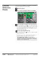
STOPPING THE
THERMOLATOR
You must shut down the Thermolator whenever you:
● Change the water hookups.
● Shut down the process machine.
● Purge the process circuit of the oil.
● Run the unit’s diagnostic tests.
● Perform routine or preventative maintenance.
● See an alarm condition that requires troubleshooting.
● Relocate, ship or store the unit.
To shut down the unit for purging the process lines, diagnostic testing, routine maintenance or troubleshooting, press the
Stop button. Then refer to the appropriate topic or section in
this User Guide.
To shut down the unit to change fluid hookups:
1
Press Stop cool and drain
the unit of all oil or fluid.
Drain the unit using the drain
plugs on the back of the heater
casting.
2
Once the unit is cool,
remove the cooling water
hookups.
Drain plug
To shut down the unit for relocation or storage:
1
Press
2
Disconnect the power supply and all water feeds.
3
Position the control panel to rest flush with the unit.
Stop
and drain the unit of all fluid.
Drain the unit using the two drain plugs.
In shipment or storage, the Thermolator can withstand an
environment between -40° F (-40° C) and 150° F (65° C)
with 95% relative humidity non-condensing.
UGH002/0514
Thermolator heaTrac TH-1 and TH-2 control
OPERATION
4-7
PERFORMING
AUTO TUNE
AN
WARNING: Electric shock hazard
This equipment is powered by high voltage. Always
disconnect and lock out the main power source
before opening the unit or the electrical enclosure to
modify factory settings. Failure to disconnect and
lock out the main power source can result in severe
personal injury.
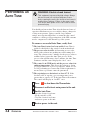
You should perform an Auto Tune after the first two hours of
operation and whenever process variables change (changes in
cooling water pressure, piping or molds; large ambient
swings; new setpoint temperature) to ensure that the control
continues to obtain good approximations of the PID constants
used to compensate for the thermal lag of the system.
To ensure a successful Auto Tune, verify that:
❒ The Auto Tune feature has been enabled. Auto Tune is
enabled or disabled via dip switch 2 on the motherboard.
❒ The process value is stable. A fluctuating process value
will fool the software into making inaccurate tuning decisions. The software waits 5 minutes for the process value to
stabilize before it starts the Auto Tune process. If the
process value still fluctuates after 5 minutes, the Auto Tune
terminates and the control displays the “At ti” error.
❒ The control is in STOP mode and the process value is in
ambient temperature. This allows the software to obtain
good approximations of process parameters, which are critical for performing an accurate tune. If this requirement is
not met, then a good tune cannot be guaranteed.
❒ The setpoint/process deviation is at least 25° F. If the
absolute value of setpoint - process temperature is not
greater than or equal to 25° F, the Auto Tune will terminate.
The control will display an “At dEV” error.
4-8
OPERATION
1
Press
2
3
Disconnect and lock out main power to the unit.
4
Restore power to the unit.
Stop
to shut down the Thermolator.
Enable Auto Tune.
Open the electrical enclosure.
Set dip switch 2 to ON.
Close the electrical enclosure
and restore power to the unit.
Thermolator heaTrac TH-1 and TH-2 control
UGH002/0514
PERFORMING
AUTO TUNE
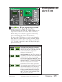
5
AN
Press Run and
(the Setpoint Select button)
simultaneously to begin the Auto Tune.
The Actual display will flash “At” and the current process
temperature to indicate that an Auto Tune is underway.
If Auto Tune is successful, the controller automatically
starts controlling using the new PID parameters.
If you press the STOP button or a fault occurs during the
Auto Tune, the control enters stop mode and Auto Tuning
immediately terminates. The actual display stops flashing
“At.” If a fault occurred, the control will display the appropriate error message.
ERROR MESSAGE
At
dEv
At
tI
At
bad
UGH002/0514
ERROR DESCRIPTION
Insufficient setpoint/process deviation.
If the absolute value of (setpoint - process
value) is less than 25° F. The Auto Tune cannot be started until the temperature
difference is at least 25° F.
Auto Tune timed out. Auto Tune will time out
if a stable process value cannot be obtained
5 minutes into the tune, or if the tuning
process takes longer than 30 minutes. If this
error occurs, verify that you followed every
requirement under “To ensure a successful
Auto Tune” and perform a second tune.
Invalid PID constants were generated.
The most likely causes of this error is a tune
started inappropriately or an external element (i.e., loose thermocouple) that upset
the process while tuning was in progress.
Verify that you followed every requirement
under “To ensure a successful Auto Tune”
and perform a second tune.
Thermolator heaTrac TH-1 and TH-2 control
OPERATION
4-9
MAINTENANCE
● Maintenance schedule . . . . . . . .5-2
● Accessing the Thermolator
enclosure . . . . . . . . . . . . . . . . .5-3
● Checking fluid level in the
reservoir . . . . . . . . . . . . . . . . . .5-4
● Performing system tests . . . . . .5-5
● Key/Display Test . . . . . . . . . . . . .5-6
● Input Test . . . . . . . . . . . . . . . . . .5-7
● Output Test . . . . . . . . . . . . . . . . .5-8
● Disabling or enabling
output monitors . . . . . . . . . . .5-9
● Calibrating temperature
sensors . . . . . . . . . . . . . . . . . .5-10
● Logging operating hours . . . . .5-12
UGH002/0514
Thermolator heaTrac TH-1 and TH-2
5-1
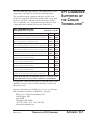
PREVENTATIVE
MAINTENANCE
SCHEDULE
Thermolator heaTrac TH-1 and TH-2 oil temperature controllers are essentially maintenance-free. However, to maintain
the best performance, we recommend the following maintenance schedule.
● Whenever process variables change
❒ Perform an Auto Tune.
The Auto Tune ensures that the control continues to
obtain good approximations of the PID constants used
to compensate for the thermal lag of the system.. You
should perform an Auto Tune after the first two hours of
operation and whenever the process changes, such as
after a mold change; installation of different pipe sizes;
or change in process setpoint. See the “Performing an
Auto Tune” in the OPERATION section.
● Daily
❒ Check for leaks in cooling and process lines.
Before and during operation, you should inspect the
unit and all plumbing lines for leaks. If a leak develops,
stop the Thermolator and repair it.
❒ Keep the unit and the area around it clean.
Check for and remove lint, dust or other obstructions on
the unit, especially around air intake areas. Keep the
floor around the unit dry.
❒ Check the process fluid level.
HTR1-500’s have an internal reservoir that
contains the process fluid. Check the level indicator on
the back of the unit to make sure the reservoir contains
an adequate amount of process fluid. Refill as needed
with the specified heat transfer fluid.
● Monthly, or as often as needed.
❒ Inspect the fluid in the fluid reservoir.
For at least the first three months of operation, check
the sight glass in the process fluid reservoir for
debris or discoloration that could indicate fluid
contamination or degradation. Replace as required.
● Quarterly (every 3 months)
❒ Inspect power cords, wires and electrical
connections.
Check for loose or frayed wires, burned contacts, and
signs of overheated wires. Check exterior power cords
to the main power source and from the electrical box to
the pump and heating elements. Check the ground wire
and thermocouple connections. Replace any wire that
appears damaged or has worn or cracked insulation.
5-2
MAINTENANCE
Thermolator heaTrac TH-1 and TH-2 control
UGH002/0514
● Annually (every 12 months)
❒ Test and calibrate the unit’s control systems.
The Thermolator’s Test Mode checks the operation
of displays, control buttons, inputs and outputs. You
can also calibrate the supply and return thermocouples.
See “Performing System Tests” in this section.
WARNING: Electrical shock and
hot surface hazards
Before attempting maintenance of any kind
on the Thermolator, you must stop the unit;
disconnect and lockout the main power
supply; and allow the unit to cool to less than
100° F (38° C)
PREVENTATIVE
MAINTENANCE
SCHEDULE
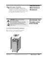
ACCESSING THE
THERMOLATOR
ENCLOSURE
To access the Thermolator enclosure:
Remove the top access panel by lifting straight up.
Remove the side panels by lifting straight up.
UGH002/0514
Thermolator heaTrac TH-1 and TH-2 control
MAINTENANCE
5-3
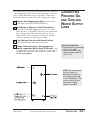
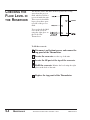
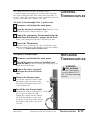
CHECKING THE
FLUID LEVEL IN
THE RESERVOIR
The heaTrac TH-1 and TH-2 models separate the cooling
water from the process
fluid, which is held in a
reservoir inside the unit.
This reservoir should be
kept at least three-quarters full of the process
fluid.
You can check the fluid
level in the reservoir
using the sight glass on
the back of the
Thermolator.
To fill the reservoir:
5-4
MAINTENANCE
1
Disconnect and lockout power, and remove the
top panel of the Thermolator.
2
Locate the reservoir near the top of the unit.
3
Locate the fill port at the top of the reservoir.
4
Refill the reservoir. Monitor the level using the sight
5
Replace the top panel of the Thermolator.
glass on the back of the unit.
Thermolator heaTrac TH-1 and TH-2 control
UGH002/0514
The TH-1 and TH-2 Thermolators provide a Test Mode that
tests displays and keys on the control panel, as well as inputs
and outputs. The Test Mode also allows calibration of the supply and return line thermocouples.
PERFORMING
SYSTEM TESTS
System tests and calibration should be performed annually.
To enable Test Mode:
1
Press
2
Disconnect and lock out main power to the unit,
then open the electrical enclosure.
3
Set dip switches 3 and
5 to OFF.
4
5
Set dip switch 6 to ON.
Stop
to shut down the Thermolator.
8 7 6 5 4 3 2 1
Close the electrical enclosure and restore
power to the unit.
◆ The control displays “tSt.”
◆ The Test Mode LED lights.
6
7
Press any button to display the first test menu.
Test mode provides the following menus:
● Key/Display Test
● Input Test
● Output Test
● Calibration
● Total Operating Hours
● Output Monitor Enable/Disable
After performing each test, hold the Setpoint
for 3 seconds to index to the next test menu.
The procedure for each test is described on the following
pages.
UGH002/0514
Thermolator heaTrac TH-1 and TH-2 control
IMPORTANT: All normal
operating functions are
disabled while Test Mode is
enabled. To return to normal
operation, you must disable
Test Mode.
To disable Test Mode,
repeat steps 2 through 5,
setting dip switch 6 to OFF
instead of ON.
MAINTENANCE
5-5
KEY/DISPLAY
TEST
The Key/Display Test verifies the function of displays, LEDs
and buttons on the control panel.
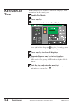
1
Enable Test Mode.
2
3
Press any key.
If necessary, index to the Key/Display menu.
Press and hold the Setpoint
key for 3 seconds to index
to each test menu until the controller displays “dSP”.
4
5
Press any key to clear all displays.
6
Exit the test and enter the next test.
Repeatedly press any key to test displays.
With each key press, a new segment of all six 8-segment
LEDs and a select group of LED indicator lights will illuminate.
Press and hold the Setpoint
and index to the next test.
5-6
MAINTENANCE
key for 5 seconds to exit
Thermolator heaTrac TH-1 and TH-2 control
UGH002/0514
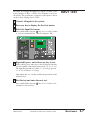
The Input Test verifies the function of inputs available on the
various models of TH-1 or TH-2 . Not all inputs are used on
all models. The performance evaluation of the inputs is based
on the voltage sensing device (VSD).
1
Connect all inputs to the system.
2
3
Press any key to display the first test menus.
INPUT TEST
Select the Input Test menu.
Press and hold the Setpoint
key for 3 seconds to index
to each test menu until the controller displays “InP”.
4
Repeatedly press and release any key to test.
With each key press and release, the left display will indicate the number of the input being tested (v1, v2, v3, etc.).
The right display indicates either “1” for voltage present
or “O” for an absence of voltage.
Only inputs that are actually used by the particular model
will be tested.
5
Exit the test and enter the next test.
Press and hold the Setpoint
and index to the next test.
UGH002/0514
key for 3 seconds to exit
Thermolator heaTrac TH-1 and TH-2 control
MAINTENANCE
5-7
OUTPUT TEST
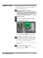
The Output Test verifies the function of outputs available on
the various models of TH-1 or TH-2 . Not all outputs are used
on all models. The performance evaluation of the inputs is
based on the output monitors (OM).
1
Connect all outputs to the system.
IMPORTANT: Testing each output requires the firing of the associated solid state relay. Make sure an
output device is connected to the controller, otherwise the test result will be erroneous.
2
3
4
Enable Test Mode.
Press any key to display the first test menus.
Select the Output Test menu.
Press and hold the Setpoint
key for 3 seconds to index
to each test menu until the controller displays “oUt”.
5
Repeatedly press and release any key to test.
With each key press and release, the left display will indicate the number of the output being tested (oS1= OM1;
oS2 = OM2; etc.). The right display indicates either “1”
for a good output or “O” for a failed output.
Only outputs that are actually used by the particular model
will be tested.
6
Exit the test and enter the next test.
Press and hold the Setpoint
and index to the next test.
5-8
MAINTENANCE
key for 3 seconds to exit
Thermolator heaTrac TH-1 and TH-2 control
UGH002/0514
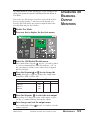
All output monitors on the Thermolator can be enabled or disabled permanently through the OM Enable/Disable Menu in
Test Mode.
You need to use this feature if you have replaced the motherboard, or if dip switches 7 and 8 have been changed erroneously. This will enable any required output monitors that
were disabled and give fuse failures.
1
2
Enable Test Mode.
3
Select the OM Enable/Disable menu.
DISABLING
ENABLING
OUTPUT
MONITORS
OR
MAINTENANCE
5-9
Press any key to display the first test menus.
Press and hold the Setpoint
key for 3 seconds to index
to each test menu until the controller indicates “oS1” in
the actual display and the status of the selected output in
the Select display.
4
Press the Setpoint ▲ or ▼ key to change the
status. Each press of the key changes the output status
from ON to OFF or OFF to ON.
OUTPUT MONITOR SELECTION GUIDE
OM1 Pump
OM2 Heat
OM3 Cool
OM4 Vent
ON
ON
ON
ON
5
Press the Setpoint
6
Save changes and exit the output menu.
to select the next output.
Repeat Step 4 to change the status of the output, or press
any key to continue indexing through the outputs.
Press and hold the Select
changes and exit.
UGH002/0514
key for 3 seconds to save the
Thermolator heaTrac TH-1 and TH-2 control
CALIBRATING
TEMPERATURE
SENSORS
Special Tools Needed:
❒ type K thermocouple
calibrator
The TH-1 and TH-2 Thermolators use type “K” thermocouples to sense the temperature in the return and supply process
lines. These thermocouples should be calibrated annually, or
when a new thermocouple is installed, to ensure correct operation.
The Thermolator’s Calibration Mode provides zero and span
calibration of both the supply and return line thermocouples.
You access the Calibration Mode while in Test Mode.
1
Enable Test Mode.
See “Performing System Tests.”
2
3
Press any button to display the first test menu.
Select the Calibration Mode menu.
Press and hold the Setpoint
key for 3 seconds to index
to each test menu until the controller indicates “SC.L” in
the Actual display.
4
Release the Setpoint
CALIBRATION
Zero Calibrate Supply Sensor
Zero Calibrate Return Sensor
Span Calibrate Supply Sensor
Span Calibrate Return Sensor
5
5-10
MAINTENANCE
key.
You are now in calibration mode. Each press and release
of this key will exit the current calibration and start the
next calibration. The table below lists the calibrations that
will be performed.
SETPOINT
DISPLAY
ACTUAL
DISPLAY
32° F (0° C)
32° F (0° C)
510° F (266° C)
510° F (266° C)
SC.L
rC.L
SC.H
rC.H
Using the thermocouple calibrator, apply the
appropriate temperature to the control input.
Thermolator heaTrac TH-1 and TH-2 control
UGH002/0514
6
Press the up ▲ key to begin calibrating.
The controller displays the name of the current calibration
(examples: 32 SC.L; 32 rC.L; 510 SC.H; or 510 rC.H).
7
CALIBRATING
TEMPERATURE
SENSORS
Wait until the control displays “don” or “bad.”
A “don” message in the Setpoint display indicates the calibration was successful. A “bad” message in the Setpoint
display indicates a bad calibration.
NOTE: The original calibration value stored in
EEProm can be restored for the current calibration
by pressing the STOP key at any time.
8
Press Select
to start the next calibration.
Pressing and releasing the Select
key at the end of a
calibration tells the controller to perform the next calibration.
9
Exit Calibration Mode.
Press and hold the Select
Calibration Mode.
key for 3 seconds to exit the
You can now proceed to the next test in Test Mode, or
disable Test Mode and resume normal operation.
TO DISABLE TEST MODE, complete steps 2
through 5 in “Performing System Tests”, setting dip
switch 6 to OFF instead of ON.
UGH002/0514
Thermolator heaTrac TH-1 and TH-2 control
MAINTENANCE
5-11
LOGGING
OPERATING
HOURS
You can see the total numbers of operation by accessing the
Total Operating Hours Log in Test Mode.
1
2
Enable Test Mode.
3
Index through test menus to the operating log.
Press any key to display the first test menus.
Press and hold the Setpoint
key for 3 seconds to index
to each test menu until the Actual display indicates “Log”.
The Setpoint display indicates the total number of operating hours in 100-hour units.
4
Exit the Operating Hours Log.
Press and hold the Select
index to the next test.
key for 3 seconds to exit and
You can now proceed to another menu in Test Mode, or
disable Test Mode and resume normal operation.
TO DISABLE TEST MODE, complete steps 2
through 5 in “Performing System Tests”, setting dip
switch 6 to OFF instead of ON.
5-12
MAINTENANCE
Thermolator heaTrac TH-1 and TH-2 control
UGH002/0514
TROUBLESHOOTING
● Before beginning . . . . . . . . . . . .6-2
● A few words of caution . . . . . . .6-2
● How to identify the cause
of a problem . . . . . . . . . . . . . . .6-3
DIAGNOSTICS
● Shut down alarms . . . . . . . . . . .6-4
● Warning alarms . . . . . . . . . . . . .6-8
● System alarms . . . . . . . . . . . . .6-11
● Thermolator will not power up .6-12
REPAIR
● Checking and replacing fuses .6-13
● Resetting overloads . . . . . . . . .6-14
● Replacing the pump overload .6-14
● Replacing the motherboard . . .6-15
● Replacing the heater
contactor . . . . . . . . . . . . . . . .6-16
● Checking and replacing
thermocouples . . . . . . . . . . .6-17
● Repairing solenoid valves . . . .6-18
● Replacing heater elements . . .6-20
● Removing the pump . . . . . . . . .6-21
UGH002/0514
Thermolator heaTrac TH-1 and TH-2
6-1
BEFORE
BEGINNING
You can avoid most problems by following the recommended
installation, operation and maintenance procedures outlined in
this User Guide. If you do have a problem, this section will
help you determine what caused it and tell you how to fix it.
Before you begin troubleshooting:
❏ Find the wiring, plumbing and other diagrams
that were shipped with your equipment. These
diagrams are the best reference for correcting a problem.
The diagrams also will note any custom features, such as
special wiring, control or plumbing options, not covered in
this User Guide.
❏ Verify that you have manuals for other equipment in the process line. Solving problems may
require troubleshooting malfunctions or incorrect operating
procedures on other pieces of equipment.
❏ If an alarm is present, note any indicator lights
and messages shown on the control panel. These
indicators will help you discover the cause of the problem
more quickly.
A FEW WORDS
OF CAUTION
The Thermolator is equipped with many safety devices. Do
not remove or defeat them. Improper corrective action can
lead to hazardous conditions, and should never be attempted
to sustain production.
WARNING: This machines should be
adjusted and serviced only by qualified technical personnel who are familiar with construction and operation of this type of equipment.
WARNING: Hot surfaces and liquids
Allow the Thermolator to cool to below
100° F (38° C) before servicing the unit.
DANGER: Voltage hazard.
Troubleshooting the electrical system of this
equipment requires use of precision electronic
measuring equipment, and may require access
to the electrical enclosure while power is on.
Exposure to potentially fatal voltage levels may
be unavoidable. These troubleshooting procedures should be performed only by qualified
electrical technicians who know how to use
this precision electronic equipment and who
understand the hazards involved.
6-2
TROUBLESHOOTING
Thermolator heaTrac TH-1 and TH-2 control
UGH002/0514
Most Thermolator malfunctions are indicated by an illuminated alarm light and error codes displayed on the control panel.
A problem can trigger three types of alarms:
● Shut Down Alarms: The Thermolator detected a problem
that caused it to shut down automatically to prevent equipment damage or personal injury.
● Warning Alarms: The Thermolator continues to operate,
but warns of a problem that could lead to a condition that
will shut down the unit.
● System Errors: The system error codes indicate a nonrecoverable problem with the microprocessor control.
HOW TO IDENTIFY
THE CAUSE OF A
PROBLEM
When the Thermolator control detects a problem, the red
Alarm light is activated and the RUN/STOP light changes
from green to flashing red.
A status light
that turns from
green to red
indicates an
alarm condition.
When an Alarm condition occurs:
1
Press
alarm.
to silence any optional audible
◆ The RUN/STOP light changes from flashing red to
steady red.
2
Note any indicator lights or error messages to
help determine the cause of the problem.
3
Find the alarm or error code in the diagnostics
tables in the TROUBLESHOOTING section of this manual.
4
Press Stop to clear the alarm and shut down
the Thermolator to correct the problem.
Press Run to resume normal operation after
the problem is corrected.
UGH002/0514
Thermolator heaTrac TH-1 and TH-2 control
WARNING:
Disconnect and lockout
the main power source
before opening the
Thermolator or its electrical enclosure for servicing. Disconnect oil and
water lines as needed.
TROUBLESHOOTING
6-3
SHUT DOWN
ALARMS
The Thermolator has detected a problem that could lead to equipment damage or personal injury if it is not corrected.
◆ The Alarm LED lights and the STOP/RUN LED flashes red.
◆ The Thermolator automatically shuts down.
◆ The control displays a red LED or alarm code indicating the
source of the problem.
Alarm
Pump
The pump motor
overload has
tripped. The
contact is open.
WARNING:
Possible cause
Solution
Is the correct voltage
supplied to the pump
motor?
Supply voltage should match
the rating on the pump name
plate. If voltage is correct,
check wiring connections.
Is the required water flow ❒ Review pump sizing
greater than the pump’s
for the application.
capacity?
❒ Decrease the water flow
from the process.
Is the motor overload
faulty or set incorrectly?
Disconnect the power and open
the electrical enclosure. Verify
that the overload is set to trip at
the proper amperage, which
should not exceed the FLA.
Manually trip and reset the
overload. If the problem continues, replace the overload. See
Resetting and Replacing
Overloads.
Is the pump working
properly?
Replace the pump if supply
voltage, wiring and overload
settings are correct, but the
pump continues to draw excessive current.
Only qualified
electrical service personnel should examine
and correct problems
that require opening
the unit's electrical
enclosure or checking
electrical current to
diagnose the cause of
a problem.
6-4
TROUBLESHOOTING
Thermolator heaTrac TH-1 and TH-2 control
UGH002/0514
The Thermolator has detected a problem that could lead to equipment damage or personal injury if it is not corrected.
◆ The Alarm LED lights and the STOP/RUN LED flashes red.
◆ The Thermolator automatically shuts down.
◆ The control displays a red LED or alarm code indicating the
source of the problem.
Alarm
High Temp. Safety
The actual temperature of oil
supplied to the
process exceeds the
510° F safety switch
limit.
WARNING:
Only qualified electrical service personnel
should examine and
correct problems that
require opening the
unit's electrical
enclosure or checking
electrical current to
diagnose the cause of
a problem.
Hi
SAF
The actual temperature of oil
supplied to the
process exceeds the
programmed 510° F
safety limit.
WARNING:
Only qualified electrical service personnel
should examine and
correct problems that
require opening the
unit's electrical
enclosure or checking
electrical current to
diagnose the cause of
a problem.
UGH002/0514
SHUT DOWN
ALARMS
Possible cause
Solution
Has oil stopped flowing
through the unit or
between the supply outlet
and return inlet?
❒ Verify that the unit is running and that the pump is
working. Verify all process
line valves are open.
Is the electro-mechanical
safety switch improperly
set or defective?
Check the switch setting. A
too-low setting will cause
nuisance trips. Check the
switch and replace if defective.
See Checking and Replacing
Switches.
Has the heater contactor
failed?
Replace the contactor if
defective. See Replacing
the Heater Contactor.
Has oil stopped flowing
through the unit or
between the supply outlet
and return inlet?
❒ Verify that the unit is running and that the pump is
working.Verify all process
valves are open.
Has the heater contactor
failed?
Replace the contactor if
defective. See Replacing
the Heater Contactor.
Thermolator heaTrac TH-1 and TH-2
TROUBLESHOOTING
6-5
The Thermolator has detected a problem that could lead to equipment damage or personal injury if it is not corrected.
◆ The Alarm LED lights and the STOP/RUN LED flashes red.
◆ The Thermolator automatically shuts down.
◆ The control displays a red LED or alarm code indicating the
source of the problem.
SHUT DOWN
ALARMS
Alarm
Lo
SAF
Possible cause
Solution
Is the cooling valve stuck
open?
Disassemble the cooling valve
and check for particles blocking the valve seat. Check the
valve seat for excessive wear.
Replace parts as required using
a valve repair kit. See
Repairing Solenoid Valves.
Has the heater failed?
Check for a bad heating
element, or a heater contactor
that failed in the open position.
See Replacing the Heater
Contactor and Replacing
Heater Elements.
Is the thermocouple
loose?
Check for a loose thermocouple or loose wire connections
to the thermocouple.
Has the thermocouple
failed?
Check the thermocouple and
replace if necessary. See
Checking and Replacing
Thermocouples.
Is the thermocouple
loose?
Check for a loose thermocouple or loose wire connections
to the thermocouple.
Has the thermocouple
failed?
Check the thermocouple and
replace if necessary. See
Checking and Replacing
Thermocouples.
Actual temperature
of oil supplied to
the process is below
the programmed
50° F safety limit.
Pbr
Err
The thermocouple
in the process
return line failed.
PbS
Err
The thermocouple
in the process
supply line failed.
6-6
TROUBLESHOOTING
Thermolator heaTrac TH-1 and TH-2
UGH002/0514
SHUT DOWN
ALARMS
The Thermolator has detected a problem that could lead to equipment damage or personal injury if it is not corrected.
◆ The Alarm LED lights and the STOP/RUN LED flashes red.
◆ The Thermolator automatically shuts down.
◆ The control displays a red LED or alarm code indicating the
source of the problem..
Alarm
PHS
Err
Possible cause
Solution
Is the pump rotating in
the wrong direction?
Check pump rotation against
the arrow stamped on the
pump. If the pump is rotating
in the wrong direction, disconnect and lockout the main
power source. Open the electrical enclosure, and reverse
any two leads on the power
connection.
Has one of the main supply wire leads become
disconnected?
Disconnect power and open
the electrical enclosure. Check
for loose connections in main
supply and on motherboard.
Has the indicated device
blown a fuse?
Disconnect and lockout the
main power. Open the electrical enclosure. Check for loose
wires and incorrectly installed
jumpers or terminal blocks
associated with the fuse error.
Replace the fuse, if necessary.
See Checking and Replacing
Fuses.
Is the correct device
being used for this fuse
location?
Replace the fuse, then enter
Test Mode. Turn off the Output
Monitor associated with the
fuse location and test outputs.
See Performing System Tests
and Disabling or Enabling
Output Monitors in the
MAINTENANCE section.
Has the motherboard
output channel at the
designated fuse failed?
Replace the motherboard. See
Checking and Replacing the
Motherboard.
The incoming
power is out of
phase. A leg may
have failed or is
disconnected.
NOTE: This alarm
is available only on
TH-2 models.
FUS
002
Pump fuse.
FUS
003
Heater fuse.
FUS
004
Cooling valve fuse.
FUS
005
Vent valve fuse.
UGH002/0514
Thermolator heaTrac TH-1 and TH-2
TROUBLESHOOTING
6-7
The Thermolator has detected a problem that could lead to a shut
down condition if it is not corrected.
◆ The Alarm LED lights.
◆ The Thermolator continues operating.
◆ The control displays a red LED or alarm code indicating the
source of the problem.
WARNING
ALARMS
Alarm
Low Deviation
The Thermolator
will not heat to the
setpoint temperature,
or takes too long to
reach the setpoint
temperature. The
actual temperature of
fluid supplied to the
process is lower than
the setpoint deviation allows.
WARNING:
The Thermolator should
be tested and repaired
only by qualified technicians equipped with the
correct tools and trained
in the maintenance and
repair of electrical systems and industrial
appliances.
6-8
TROUBLESHOOTING
Possible cause
Solution
Is the cooling valve stuck
open or leaking water?
Disassemble the cooling valve
and check for particles blocking the valve seat. Check the
valve seat for excessive wear.
Replace as required using a
valve repair kit. See Repairing
Solenoid Valves.
Did a heater element fail? With the unit powered down:
Check for loose connections.
Check resistance between the
phase legs on the output side
of the heater contactor.
Readings should be within
0.25 ohms of each other.
Replace the heater, if necessary. See Replacing Heater
Elements.
Did a heater contactor
fail?
With power on and the
Heater LED lit: Check the
amp draw on each of the three
phase legs to the heater. All
should match the FLA listed
for the heater on the unit
nameplate. Replace the heater
contactor if there is a voltage
imbalance greater than 10%.
See Replacing the Heater
Contactor.
Is the low deviation temperature set too low?
Increase the low deviation setting. The recommended setting
is 2° F to 10° F below the
process setpoint.
Is the Thermolator correctly sized for the application?
Review specifications and
selection guidelines that apply
to heater and pump sizes in
temperature control units.
Thermolator heaTrac TH-1 and TH-2
UGH002/0514
The Thermolator has detected a problem that could lead to a shut
down condition if it is not corrected.
◆ The Alarm LED lights.
◆ The Thermolator continues operating.
◆ The control displays a red LED or alarm code indicating the
source of the problem.
Alarm
High Deviation
The Thermolator
will not cool down,
or takes too long to
cool down. The actual temperature of
fluid supplied to the
process is higher
than the setpoint
deviation allows.
Possible cause
Solution
Has oil stopped flowing
between supply outlet
and return inlet?
Check for a plugged pipe or
closed valve.
Did the cooling valve fail? Check the cooling valve. See
Repairing Solenoid Valves
Is the temperature difference between the cooling
water supply and the setpoint too small?
The temperature difference
should be at least 25° F to
achieve proper cooling. Increase
the process setpoint, decrease
the cooling water supply temperature. or increase cooling
water supply pressure.
Did a heater contactor
fail?
With power on and the Heater
LED lit: Check the amp draw
on each of the three phase legs
to the heater. All should match
the FLA listed for the heater on
the unit nameplate. Replace the
heater contactor if there is a
voltage imbalance greater than
10%. See Replacing the Heater
Contactor.
Is the high deviation temperature set too low?
Increase the high deviation setpoint. The recommended setting
is the setpoint + 2° F to 10° F .
WARNING:
The Thermolator should
be tested and repaired
only by qualified technicians equipped with the
correct tools and trained
in the maintenance and
repair of electrical systems and industrial
appliances.
UGH002/0514
WARNING
ALARMS
Thermolator heaTrac TH-1 and TH-2
TROUBLESHOOTING
6-9
WARNING
ALARMS
The Thermolator has detected a problem that could lead to a shut
down condition if it is not corrected.
◆ The Alarm LED lights.
◆ The Thermolator continues operating.
◆ The control displays a red LED or alarm code indicating the
source of the problem.
Alarm
SPI Communication
Possible cause
Solution
Is the unit connected to a
host machine?
If the Thermolator is not connected to a host device, set the
SPI address to OFF using the
Setpoint adjustment buttons on
the control panel.
Are the network address
and baud rate correct?
❒ Check the network address.
The address may be set to
any number from 32 to 254
(a hexadecimal integer
between 20 and FE), as long
as that number has not been
assigned to another machine
connected to the same network.
❒ Make sure the baud rate
(9600, 4800, 2400, or 1200)
matches the host machine.
Is something wrong with
the cable?
Check the communication
cable condition and connections. The cable must conform
to SPI standards. Check for
loose connections on the
motherboard.
The SPI communication link has failed.
6-10
TROUBLESHOOTING
Thermolator heaTrac TH-1 and TH-2
UGH002/0514
The Thermolator has detected a non-recoverable error involving he microprocessor control.
◆ The Alarm LED lights and the STOP/RUN LED flashes red.
◆ The Thermolator shuts down or will not start.
◆ The control displays an error code indicating the source of
the problem.
Alarm
ERR
001
RAM hardware
failure.
ERR
002
ROM, checksum
failure.
ERR
003
ERR
004
SYSTEM
ALARMS
Cause
Solution
Electrical noise or failed
CPU on the motherboard
caused system write tests
do fail during power up.
Make sure all connections on
the motherboard are solid.
Operate unit in a noise free
environment. If error persists,
contact Conair service.
The CPU and/or PROM
chip (U1 or U2) is not
making good contact with
its socket, or the PROM
chip has failed.
Make sure the CPU and PROM
chips are seated correctly in the
sockets. If error persists, contact
Conair service.
A failed CPU, failed motherboard, software bug or
electrical noise caused an
internal software error.
Cycle power to the unit. If the
problem persists, contact Conair
service technicians. You may
need to replace the motherboard.
The CPU tried to execute
an illegal software instruction due to electrical noise
or a failed motherboard.
Make sure all connections to
the motherboard are solid and
that the unit is operating in a
noise free environment. If error
persists, contact Conair service.
A failed CPU, failed motherboard, software bug or
electrical noise caused an
internal software error.
Cycle power to the unit. If the
problem persists, contact Conair
service technicians. You may
need to replace the motherboard.
The memory has exceeded
its usable life or there is a
software bug. This error
occurs only after changes
have been made to nonvolatile memory either
through the operator panel
or SPI.
Cycle power to the unit.
Contact Conair service if an
operating parameter such as the
setpoint is not being saved or if
this error persists.
COP failures.
ERR
005
Illegal Opcode.
ERR
006
through
ERR
014
ERR
015
ERR
016
Software cannot
write to CPU nonvolatile memory.
UGH002/0514
Thermolator heaTrac TH-1 and TH-2
TROUBLESHOOTING
6-11
THERMOLATOR
WILL NOT
POWER UP
If you apply power to the Thermolator and the control panel does
not light, you have a problem with the main power circuit or the
unit’s microprocessor board.
Symptom
Possible cause
Solution
Applying power
does not turn on
the Thermolator or
light the control
panel.
Is power reaching the
Thermolator?
❒ Verify that the main power
supply and any customerinstalled electrical disconnect or emergency stop
devices are in the ON position.
❒ Verify correct electrical connections between the unit
and the control, and
between the unit and the
power supply. Replace any
damaged wires or cables.
Has the unit blown a
fuse?
Check Fuse 1 on the motherboard and any fuses or breakers
associated with customerinstalled disconnect devices.
Replace or reset as required.
Identify the cause of the ground
fault and correct it. See Checking and Replacing Fuses.
Is the correct voltage
reaching the
Thermolator?
Check the electrical requirements on the unit nameplate.
Verify correct main supply
voltage to the unit and the secondary voltage supply from the
transformer to unit components. Replace the transformer,
if necessary.
Is the unit in Test Mode?
If the Test Mode LED is lit,
you must disable Test Mode on
the motherboard before resuming operation. See Performing
System Tests in the
MAINTENANCE section.
The control panel is
lit, but the
Thermolator will
not operate when
RUN is pressed.
6-12
WARNING: Electrical Shock Hazard
Disconnect and lockout the main power supply
before proceeding.
TROUBLESHOOTING
Thermolator heaTrac TH-1 and TH-2
UGH002/0514
This procedure covers the factory-installed fuses on the unit’s
motherboard. If you have installed an electrical disconnect or
emergency stop switch, additional fuses and/or breakers may
have been used elsewhere in the in the main power circuit.
To replace a blown fuse:
1 Disconnect and lockout the main power.
2
CHECKING AND
REPLACING
FUSES
Open the electrical enclosure door. Turn the screw
on the front panel counterclockwise to open.
WARNING:
3
Replace the fuse. The fuses are located on the mother-
4
Close the electrical enclosure and restart the unit.
board and are labeled and identified on the orange shield.
If fuses continue to fail:
L3
L1
4
3
2
1
OPS
OPS
FSTAT
FSTAT
L2
6
5
4
3
2
1
F1
LLS/WPS
LLS/WPS
AUTOSTART
AUTOSTART
HPS/LPS
HPS/LPS
Fuse 1
Control
power
AC IN
4
AC IN + 3
AC OUT
2
AC OUT + 1
❒ Verify that the unit is receiving the correct voltage.
Check the voltage, phasing and amperage ratings on
the unit’s nameplate.
❒ Verify that the unit’s transformer is operating correctly.
Check for proper voltage (120V 10%) to the voltage
sensing device for the fuse location.
❒ Check all wiring referencing the fusing location for
loose connections, damage or improper grounding.
Verify that the correct device is being used for this fuse
location. See Disabling or Enabling Output
Monitors in the MAINTENANCE section.
3 PHASE INPUT
F5
UNLDR 1/ VENT 2 SOL
UNLDR 1/ VENT 2 SOL
UNLDR 2/ COOL 1 SOL
UNLDR 2/ COOL 1 SOL
+
+
4
3
2
1
PUMP
PUMP
PUMP OL
PUMP OL
4
3
2
1
F4
F2
OFF
1 2 3 4 5 6 7 8
ON
CONFIGURATION
DIP SWITCH
PMP AUX
PMP AUX
1FS/ COMP AUX
1FS/ COMP AUX
PUMPDOWN
PUMPDOWN
HEAT/COMP
HEAT/COMP
HTS/COMP OL
HTS/COMP OL
N
C
NC
ALARM
NO
C
110V
LLS/PURGE 3SOL
LLS/PURGE 3SOL +
PURGE 4SOL
PURGE 4 SOL +
F6
TCPL'S
6
5
4
3
2
1
4
3
2
1
6
5
4
3
2
1
Fuse 5
Vent valve
Fuse 4
Cooling valve
Fuse 2
Pump
Fuse 3
Heater
4
3
2
1
SUP RET
Y
R
R
Y
(-2) CONTROL
OPER PNL CABLE
+ 120 Ohm
+ TR
TR
GND
GND
+ TR
TR
120 Ohm
F3
1 2 3 4 5 6 7 8
UGH002/0514
Shock Hazard
Only qualified service
personnel familiar with
electrical testing and
industrial equipment
should examine and
correct problems that
require opening the
unit with power on to
diagnose the cause of
a problem.
IMPORTANT: Always
refer to the wiring diagrams that came with
your Thermolator to
locate specific electrical
components. Illustrations
in the User Guide are
intended to be representative only.
1 2 3 4
Thermolator heaTrac TH-1 and TH-2
TROUBLESHOOTING
6-13
The pump motor overload is located inside the unit’s electrical enclosure.
RESETTING
OVERLOADS
REPLACING THE
PUMP OVERLOAD
1
Disconnect and lockout the main power.
2
Open the electrical enclosure door. Turn the
screw on the front panel counterclockwise to open.
3
Check the overload.
1
Disconnect and lockout the main power.
2
Open the electrical enclosure door. Turn the screw
on the front panel counterclockwise to open.
3
Locate the pump overload module attached
4
Disconnect the three power leads from the over-
Motor contactor
If the yellow button is out, the
overload has tripped. Press the
blue button to reset the overload.
Verify that the overload trip point
does not exceed the FLA for the
pump.
to the pump motor starter.
load module to the pump motor. Note the placement of
each lead and label as needed.
5
Disconnect auxiliary wiring on
the overload module.
6
Remove the overload module.
7
Reverse these steps to install
the new overload module.
8
Set the module reset mode to
M for manual.
9
Set the proper FLA trip point.
Loosen the three screws that connect
the overload module to the motor contactor. Pull the overload module down
to release it from the starter.
Do not exceed the FLA for the pump
motor.
Motor overload
6-14
TROUBLESHOOTING
Thermolator heaTrac TH-1 and TH-2
UGH002/0514
1
Disconnect and lockout the main power supply.
2
Open the electrical enclosure door. Turn the screw
L1
L3
4
3
2
1
OPS
OPS
FSTAT
FSTAT
refer to the wiring diagrams that came with
your Thermolator to locate
specific electrical components. Illustrations in the
User Guide are intended
to be representative only.
F5
UNLDR 1/ VENT 2 SOL
UNLDR 1/ VENT 2 SOL
UNLDR 2/ COOL 1 SOL
UNLDR 2/ COOL 1 SOL
+
+
4
3
2
1
PUMP
PUMP
PUMP OL
PUMP OL
4
3
2
1
F4
F2
OFF
PMP AUX
PMP AUX
1FS/ COMP AUX
1FS/ COMP AUX
PUMPDOWN
PUMPDOWN
1 2 3 4 5 6 7 8
6
5
4
3
2
1
HEAT/COMP
HEAT/COMP
HTS/COMP OL
HTS/COMP OL
ON
CONFIGURATION
DIP SWITCH
4
3
2
1
F3
6
5
4
3
2
1
N
C
NC
NO
C
110V
LLS/PURGE 3SOL
LLS/PURGE 3SOL +
PURGE 4SOL
PURGE 4 SOL +
F6
TCPL'S
(-2) CONTROL
OPER PNL CABLE
ALARM
4
3
2
1
SUP RET
Y
R
R
Y
+ 120 Ohm
+ TR
TR
GND
GND
+ TR
TR
120 Ohm
Disconnect the wires
from the motherboard by
pulling the terminal
blocks up.
IMPORTANT: Always
3 PHASE INPUT
labeled with the connection
information. You must label the
wires to ensure they are connected to the correct terminals
on the new motherboard.
4
L2
6
5
4
3
2
1
F1
Mark or label each wire
connected to the motherboard. The orange shield is
LLS/WPS
LLS/WPS
AUTOSTART
AUTOSTART
HPS/LPS
HPS/LPS
on the front panel counterclockwise to open.
AC IN
4
AC IN + 3
AC OUT
2
AC OUT + 1
3
REPLACING THE
MOTHERBOARD
L3
L2
L1
OPS
OPS
FSTAT
FSTAT
4
3
2
1
1 2 3 4
6
5
4
3
2
1
Remove the motherboard and shield from the
F1
6
1 2 3 4 5 6 7 8
LLS/WPS
LLS/WPS
AUTOSTART
AUTOSTART
HPS/LPS
HPS/LPS
Loosen the screws holding the orange shield.
AC IN
4
AC IN + 3
AC OUT
2
AC OUT + 1
5
3 PHASE INPUT
electrical enclosure as a unit.
F5
7
UNLDR 1/ VENT 2 SOL
UNLDR 1/ VENT 2 SOL
UNLDR 2/ COOL 1 SOL
UNLDR 2/ COOL 1 SOL
Remove the motherboard from the shield
F4
PUMP
PUMP
PUMP OL
PUMP OL
and replace with the new
motherboard.
Reattach the shield and
new motherboard in the
OFF
1 2 3 4 5 6 7 8
ON
CONFIGURATION
DIP SWITCH
4
3
2
1
HEAT/COMP
HEAT/COMP
HTS/COMP OL
HTS/COMP OL
N
C
NC
ALARM
NO
C
110V
LLS/PURGE 3SOL
LLS/PURGE 3SOL +
PURGE 4SOL
PURGE 4 SOL +
F6
TCPL'S
6
5
4
3
2
1
4
3
2
1
6
5
4
3
2
1
4
3
2
1
SUP RET
Y
R
R
Y
+ 120 Ohm
+ TR
TR
GND
GND
+ TR
TR
120 Ohm
Reconnect the terminal
blocks and wires to the
new board.
PMP AUX
PMP AUX
1FS/ COMP AUX
1FS/ COMP AUX
PUMPDOWN
PUMPDOWN
F3
electrical enclosure. Tighten
the screws.
9
4
3
2
1
F2
(-2) CONTROL
OPER PNL CABLE
8
+
+
1 2 3 4 5 6 7 8
1 2 3 4
Make sure you align the terminal blocks with the correct
pins on the board. Push the terminal blocks onto the pins,
taking care not to bend any pins.
10
Set dip switches 7 and 8 to the correct unit type.
11
Program output monitors on the new board.
Set Dip switch 7 to OFF and dip switch 8 to ON.
See Disabling or Enabling Output Monitors in the
MAINTENANCE section.
UGH002/0514
Thermolator heaTrac TH-1 and TH-2 control
TROUBLESHOOTING
6-15
REPLACING THE
HEATER
CONTACTOR
IMPORTANT: Always
refer to the wiring diagrams that came with
your Thermolator to
locate specific electrical
components. Illustrations
in the User Guide are
intended to be representative only.
WARNING: Electrical Shock Hazard
Only qualified service personnel who have been
trained on electrical testing and the procedures for
avoiding the hazards should diagnose or correct problems that require opening the unit with power on.
Thermolators use mercury displacement heater contactors.
The heater contactors should be replaced if:
● You have checked the amp draw on each of the three-phase
legs and discovered a voltage imbalance greater than 10%.
● You have checked the continuity and found that ohms at
the coil equal zero.
To replace the heater contactor:
1
Disconnect and lockout the main power.
2
Open the electrical enclosure door. Turn the
screw on the front panel counterclockwise to open.
3
Disconnect the wires from the heater contactor
contactor. Make sure you label the wires to ensure you
can connect them correctly to the new contactor.
4
Remove the contactor
5
Discard the old contactor using the proper
disposal procedure. See
by removing the screws that
hold it in place.
Heater contactor
Material Safety Data Sheet
#7439-97 in the APPENDIX.
6
Reverse this procedure
to install the new contactor. Make sure the wires
are connected correctly.
WARNING: Hazardous Substance
Thermolators use mercury displacement contactors. Mercury is considered a hazardous substance
and must be dealt with accordingly. See Material
Safety Data Sheet #7439-97-6 for information on
the how to avoid the potential hazards and how to
clean up and dispose of mercury if it spills.
6-16
TROUBLESHOOTING
Thermolator heaTrac TH-1 and TH-2 control
UGH002/0514
The Thermolator uses two type ‘K’ thermocouples
to monitor supply and return process temperatures. One thermocouple is installed in the wall of the heater tank at the “to
process” outlet. The other thermocouple is installed in the wall
of the cooling tank at the “from process” inlet.
CHECKING
THERMOCOUPLES
To check a thermocouple after a probe error:
1 Disconnect and lockout the main power.
2
3
Open the electrical enclosure door. Turn the screw
on the front panel counterclockwise to open.
Unplug the appropriate thermocouple from the
motherboard and install a jumper on the leads.
Refer to the wiring diagrams that came with your unit.
4
Restart the Thermolator.
◆ If error message disappears, replace the thermocouple.
◆ If error message does not disappear, replace the motherboard. See Replacing the Motherboard.
To replace a thermocouple:
1 Disconnect and lockout the main power.
2
Shut off the process valves (if installed) and
drain the unit. Drain all oil using the drain plugs located the bottom of the unit.
3
Remove the unit’s top panel
and open the electrical enclosure
4
Remove the thermocouple.
5
REPLACING
THERMOCOUPLES
Loosen the compression nut to slide
the thermocouple out of the casing.
Disconnect the thermocouple wires
at the motherboard.
WARNING:
Hot surfaces
Allow the Thermolator
to cool to below 100° F
(38° C) before servicing
the unit.
Nut
Install the new thermocouple.
Insert the tip of the new thermocou- Thermocouple
ple at least 1 inch into the tank.
tighten the compression nut. Thread
the leads through the raceway leading to the electrical enclosure. Attach
the thermocouple leads to the motherboard.
UGH002/0514
Thermolator heaTrac TH-1 and TH-2 control
TROUBLESHOOTING
6-17
REPAIRING
SOLENOID
VALVES
Every Thermolator has a solenoid valve assembly that controls
the cooling water out flow.
WARNING: Electrical shock and
hot surface hazards
Before attempting maintenance of any kind
on the Thermolator, you must stop the unit;
disconnect and lockout the main power supply;
and allow the unit to cool to 100° F (38° C)
1
Shut off the cooling water infeed.
2
Drain the unit of all water through the manual lever
3
Remove the cooling water inlet feed.
4
5
Disconnect and lockout main power.
on the pressure relief valve.
Remove the top and side panels of the
Thermolator. Lift the top panel straight up, then lift the
side panels up.
6 Remove the solenoid valve
from the cooling water inlet
line.
7 Disassemble the solenoid
valve.
(see exploded views on next page.
8
Inspect and clean or repair
the valve body assembly.
Remove foreign particles and
replace damaged parts as necessary.
9
Reassemble the valve and other components.
Reassemble in reverse order. Seal all pipe fittings
with pipe sealant. Check that all flows are in the correct
direction. Check for leaks before resuming operation.
6-18
TROUBLESHOOTING
Thermolator heaTrac TH-1 and TH-2 control
UGH002/0514
REPAIRING
SOLENOID
VALVES
*Indicates Parts Supplied
in Solenoid Enclosure Kit
Retaining Clip*
or
Retaining Cap*
Nameplate
Cover*
Sleeve*
Grounding Wire
Yoke*
(Not present on all constructions)
Insulating Washer
Housing*
7/8" Dia. Hole
for 1/2" Conduit
Coil
Solenoid Base
Sub-Assembly
Insulating Washer
Sleeve*
0.9375-26 UNS-2A
Thread
Core (AC)
Tapped Hole in Core
0.250-28 UNF-2B
0.38 Minimum Full Thread
Alternate Construction with
Nameplate on Housing
*Indicates Parts Supplied
in Solenoid Enclosure Kit
or
Retaining Clip*
Cover*
Spring
Washer*
Yoke*
Sleeve*
Housing*
with Nameplate*
7/8" Dia. Hole
for 1/2" Conduit
Grounding Wire
(Not present on all constructions)
Coil
Solenoid Base
Sub-Assembly
Sleeve*
0.9375-26 UNS-2A
Thread
Core (AC)
UGH002/0514
Tapped Hole in Core
0.250-28 UNF-2B
0.38 Minimum Full Thread
Thermolator heaTrac TH-1 and TH-2 control
TROUBLESHOOTING
6-19
REPLACING
HEATER
ELEMENTS
WARNING: Electrical shock and
hot surface hazards
Before attempting maintenance of any kind
on the Thermolator, you must stop the unit;
disconnect and lockout the main power
supply; and allow the unit to cool to less than
100° F (38° C)
1
2
3
Disconnect and lockout the main power.
4
Remove the heater wiring
harness.
Remove the heater cap.
Use a 1/4-inch open-end wrench
to remove the three bolts that
hold the cap to the heater tank.
5
6
Shut off the cooling water in feed.
7
Remove the four bolts
that hold the heater element in place. Use a 15/16-
8
Drain the Thermolator using the drain plugs
located at the rear of the unit.
9
10
TROUBLESHOOTING
Heater cap
inch socket with 1/2-inch drive.
Heater element
Lift the heating element
out of the heater tube.
Heater
gasket
Lift the element straight up.
6-20
Heater
cap
Label the wiring layout of the
heater terminals; wires are
labeled 2T1, 2T2, 2T3 and
GND. Then unscrew the locking screws on the wiring harness
and remove the wires.
IMPORTANT: Always
refer to the wiring diagrams that came with
your Thermolator to
locate specific electrical
components. Illustrations
in the User Guide are
intended to be representative only.
Remove the top panel of the Thermolator.
Replace the heater gasket
Use a high temperature Teflon
paste to ensure a good seal.
Reverse these steps to
install the new heater
element and reassemble
the unit.
Thermolator heaTrac TH-1 and TH-2 control
UGH002/0514
WARNING: Electrical shock and
hot surface hazards
Before attempting maintenance of any kind
on the Thermolator, you must stop the unit;
disconnect and lockout the main power
supply; and allow the unit to cool to less than
100° F (38° C)
1
Disconnect and lockout the main power.
2
Shut off the cooling water in feed.
3
Remove the top and side panels of the
Thermolator.
4
Drain the unit of all fluid. Remove the drain plugs at
the rear of the heater casting.
5
Remove the seal flush line. Use a 1/2-inch open-end
wrench to remove the vent line from the connection on the
pump adapter.
the pump
6 Remove
assembly bolts. Use a
REMOVING
THE PUMP
Pump
assembly
bolts
9/16-inch open-end box
wrench to remove the bolts
holding the pump to the
volute case. The bolt in the
rear will require a 9/16-inch
crows foot wrench.
7
Lift the pump assembly
straight up to remove.
Pump seal flush line
The pump can now be replaced
or disassembled for repair.
8
Reverse the steps to
reassemble the unit.
NOTE: Before restarting,
close all drain openings using
sealant on the threads and
refill the unit with fluid. Do not
start the the pump when the
unit is dry.
UGH002/0514
Thermolator heaTrac TH-1 and TH-2 control
TROUBLESHOOTING
6-21
Conair has made the largest investment in customer support in
the plastics industry. Our service experts are available to help
with any problem you might have installing and operating
your equipment. Your Conair sales representative also can help
analyze the nature of your problem, assuring that it did not
result from misapplication or improper use.
WE’RE HERE
TO HELP
To contact Customer Service personnel, call:
HOW TO CONTACT
CUSTOMER
SERVICE
From outside the United States, call: 814-437-6861
You can commission Conair service personnel to provide onsite service by contacting the Customer Service Department.
Standard rates include an on-site hourly rate, with a one-day
minimum plus expenses.
If you do have a problem, please complete the
following checklist before calling Conair:
❒ Make sure you have all model, serial and parts list
numbers for your particular equipment. Service
personnel will need this information to assist you.
BEFORE YOU
CALL ...
❒ Make sure power is supplied to the equipment.
❒ Make sure that all connectors and wires within
and between control systems and related
components have been installed correctly.
❒ Check the troubleshooting guide of this manual
for a solution.
❒ Thoroughly examine the instruction manual(s)
for associated equipment, especially controls.
Each manual may have its own troubleshooting
guide to help you.
❒ Check that the equipment has been operated as
described in this manual.
Additional manuals and
prints for your Conair
equipment may be
ordered through the
Customer Service or
Parts Departments for
a nominal fee.
❒ Check accompanying schematic drawings for
information on special considerations.
IMS0002/0296
SERVICE INFORMATION
APPENDIX A-1
EQUIPMENT
GUARANTEE
PERFORMANCE
WARRANTY
Conair guarantees the machinery and equipment on this order,
for a period as defined in the quotation from date of shipment,
against defects in material and workmanship under the normal
use and service for which it was recommended (except for
parts that are typically replaced after normal usage, such as
filters, liner plates, etc.). Conair’s guarantee is limited to
replacing, at our option, the part or parts determined by us to
be defective after examination. The customer assumes the cost
of transportation of the part or parts to and from the factory.
Conair warrants that this equipment will perform at or above
the ratings stated in specific quotations covering the equipment or as detailed in engineering specifications, provided the
equipment is applied, installed, operated and maintained in the
recommended manner as outlined in our quotation or specifications.
Should performance not meet warranted levels, Conair at its
discretion will exercise one of the following options:
● Inspect the equipment and perform alterations or
adjustments to satisfy performance claims. (Charges
for such inspections and corrections will be waived
unless failure to meet warranty is due to misapplication, improper installation, poor maintenance practices
or improper operation.)
● Replace the original equipment with other Conair
equipment that will meet original performance claims
at no extra cost to the customer.
● Refund the invoiced cost to the customer. Credit is
subject to prior notice by the customer at which time a
Return Goods Authorization Number (RGA) will be
issued by Conair’s Service Department. Returned
equipment must be well crated and in proper operating
condition, including all parts. Returns must be prepaid.
Purchaser must notify Conair in writing of any claim and provide a customer receipt and other evidence that a claim is
being made.
WARRANTY
LIMITATIONS
APPENDIX A-2
Except for the Equipment Guarantee and Performance
Warranty stated above, Conair disclaims all other warranties with respect to the equipment, express or
implied, arising by operation of law, course of dealing,
usage of trade or otherwise, including but not limited to
the implied warranties of merchantability and fitness for
a particular purpose.
WARRANTY INFORMATION
IMS0003/0796
B-1
B-2
B-3
B-4
PUMP
CURVES
UGH002/0514
TECHNICAL INFORMATION
APPENDIX C-1
The SPI commands supported by Conair Thermolator® mold
temperature controllers are listed in the following tables.
The standard required commands and three optional commands are listed in the SPI Command Pairs table, along with
the Select and Poll command pairs in hexadecimal format.
Select commands set or change Thermolator functions. Poll
commands retrieve information from the Thermolator.
SPI COMMANDS
SUPPORTED BY
THE CONAIR
THERMOLATOR®
SPI Command Pairs
Mold temperature controllers
Device ID: hex 20
Commands
Echo
- Select stores 4 bytes of information at the Thermolator; Poll retrieves it.
Setpoint Process Temperature
- Sets and retrieves the process temperature setpoint.
Alarm, High Temperature Deviation*
- Sets the alarm band temperature; retrieves setpoint + alarm band value.
Alarm, Low Temperature Deviation*
- Sets the alarm band temperature; retrieves setpoint + alarm band value.
Mode, Machine
- Start/stops the Thermolator; acknowledges alarms; retrieves run status
Version
- Retrieves 4 bytes of SPI version information.
Process Status
- Retrieves run status and alarm conditions.
Status, Machine 1
- Retrieves run status and alarm conditions.
Status, Machine 2
- Retrieves run status and alarm conditions.
Temperature, from Process
- Retrieves the actual temperature of fluid returning to the Thermolator.
Select
0x20
0x21
0x20
0x31
0x20
0x33
0x20
0x35
0x20
0x49
Poll
0x20
0x20
0x20
0x30
0x20
0x32
0x20
0x34
0x20
0x48
0x20
0x22
0x20
0x40
0x20
0x42
0x20
0x44
0x20
0x72
* NOTE: Both High and Low Temperature Deviation commands set the
same variable. Use only one of these commands to avoid problems.
See the tables on the following pages for the SPI status words
and BIT positions for Process Status, Machine 1 Status and
Machine 2 status.
For more information on the SPI protocol, you can obtain the
SPI Communication Protocol Manual by contacting:
The Society of the Plastics Industry, Inc.
1801 K Street, NW
Suite 600K
Washington DC 20006
(202) 974-5200 Fax: (202) 296-7005
www.plasticsindustry.org
IMH001/0300
THERMOLATOR SPI COMMANDS
APPENDIX D-1
SPI STATUS WORDS
Status, Process
Reserved
Reserved
Alarm, Low flow
Reserved
Alarm, Low pressure condition
Alarm, High pressure condition
Alarm, Low temperature deviation
Alarm, High temperature deviation
13
12
11
10
9
8
7
6
5
4
EEprom error
A/D converter error
CJC Error
RAM hardware
ROM checksum
Probe Failure
E/M Hi temp safety
Prog. Hi temp safety
Output monitor failure
Low water pressure
High deviation alarm
Low deviation alarm
Prog. Lo temp safety
Processing
Reserved
14
Alarm, System
Reserved
15
Alarm, Process
Open
Word BIT position
Alarm, Machine
SPI STATUS WORD
Open
Poll: 0x20 0x40
3
2
1
0
SET
SET
SET
SET
SET
SET
SET
SET
*
*
*
*
*
*
*
*
*
*
*
*
*
*
*
*
*
SET
SET
SET
SET
SET
SET
SET SET
SET SET
SET
SET
SET
SET
SET
SET
Pump overload
Low water level
Test Mode
Phase error
SET SET
SET
NOTES:
The SPI I/O list defines the Processing bit as being cleared if the unit is not processing; otherwise it is SET.
*Elsewhere
on the chart:
●
If a bit is not shown to be SET, it is cleared.
The System Alarm bit is SET if an alarm is present. It is the logical OR of Process alarm and Machine alarm.
● Processing, System Alarm, Process Alarm and Machine Alarm bits are repeated for Process Status, Machine 1
Status and Machine 2 Status.
●
APPENDIX D-2
THERMOLATOR SPI COMMANDS
IMH001/0499
SPI STATUS WORDS
Status, Machine 1
Alarm, Low volts
Alarm, High volts
Reserved
Reserved
Alarm, Low pressure safety limit
Alarm, High pressure safety limit
Alarm, Low temperature safety limit
Alarm, High temperature safety limit
13
12
11
10
9
8
7
6
5
4
Processing
Alarm, High current
14
Alarm, System
Alarm, Low current
15
Alarm, Process
Alarm, Phase
Word BIT position
Alarm, Machine
SPI STATUS WORD
Open
Poll: 0x20 0x42
3
2
1
0
SET
SET
SET
SET
SET
SET
SET
SET
*
*
*
*
*
*
*
*
*
*
*
*
*
*
*
*
*
*
EEprom error
A/D converter error
CJC Error
RAM hardware
ROM checksum
Probe Failure
SET SET
E/M Hi temp safety
Prog. Hi temp safety
Output monitor failure
Low water pressure
High deviation alarm
Low deviation alarm
Prog. Lo temp safety
Pump overload
Low water flow
Low water level
Test Mode
Phase error
SET SET
SET
SET
SET
SET
SET
SET
SET
SET
SET
SET
SET
SET SET
SET
SET
SET
SET
SET
SET
SET
SET
NOTES:
The SPI I/O list defines the Processing bit as being cleared if the unit is not processing; otherwise it is SET.
*Elsewhere
on the chart:
●
If a bit is not shown to be SET, it is cleared.
The System Alarm bit is SET if an alarm is present. It is the logical OR of Process alarm and Machine alarm.
● Processing, System Alarm, Process Alarm and Machine Alarm bits are repeated for Process Status, Machine 1
Status and Machine 2 Status.
●
IMH001/0499
THERMOLATOR SPI COMMANDS
APPENDIX D-3
SPI STATUS WORDS
Status, Machine 2
Reserved
Reserved
Reserved
Reserved
Reserved
Reserved
Fault, CAL
Fault, Sensor
13
12
11
10
9
8
7
6
5
4
EEprom error
A/D converter error
CJC Error
RAM hardware
ROM checksum
Probe Failure
Processing
Reserved
14
Alarm, System
Reserved
15
Alarm, Process
Open
Word BIT position
Alarm, Machine
SPI STATUS WORD
Open
Poll: 0x20 0x44
3
2
1
0
SET
SET
SET
SET
SET
SET
SET
SET
SET
SET
SET
SET
*
*
*
*
*
*
*
*
*
*
*
*
*
*
*
*
*
SET
E/M Hi temp safety
Prog. Hi temp safety
Output monitor failure
Low water pressure
High deviation alarm
Low deviation alarm
Prog. Lo temp safety
Pump overload
Low water level
Test Mode
Phase error
SET
SET
SET
SET
SET
SET
NOTES:
*
The SPI I/O list defines the Processing bit as being cleared if the unit is not processing; otherwise it is SET.
Elsewhere on the chart:
● If a bit is not shown to be SET, it is cleared.
● The System Alarm bit is SET if an alarm is present. It is the logical OR of Process alarm and Machine alarm.
● Processing, System Alarm, Process Alarm and Machine Alarm bits are repeated for Process Status, Machine 1
Status and Machine 2 Status.
APPENDIX D-4
THERMOLATOR SPI COMMANDS
IMH001/0499
Material Safety Data Sheet
An explanation of the terms used in this document may be found in OSHA 29 CFR 1910.1200,
which is available from OSHA regional or area offices.
1. Chemical Identification
Substance: Mercury
Chemical name: Mercury
Formula: HG
Trade name: Not applicable
Supplier of MSDS information:
The Conair Group Inc.
One Conair Drive
Pittsburgh, PA 15202
412-312-6000
CAS-Number: 7439-97-6
Synonyms: Quicksilver; Liquid silver
Molecular weight: 200.59
Chemical family: Metal
Emergency contact:
For CHEMTREC assistance call
800-424-9300 (in the U.S.)
703-527-3887 (international)
MSDS:
7439-97-6
MERCURY
2. Composition and Exposure Limits
Material
Mercury
Weight (%)
100
Exposure Limits
3
0.05 mg/m Threshold Limit Value(skin)/TWA
3
0.1 mg/m Permissible Exposure Limit (PEL)
3. Hazards Identification
Hazard Ratings (0 = no hazard; 4 = extreme hazard):
Health
- 4 Extreme (Poison)
Carcinogenic: NTP – No
Flammability - 0 None
IARC – No
Reactivity
- 1 Slight
Z List – No
Contact
- 3 Severe (Life)
OSHA Reg – No
Personal Health Effects:
WARNING Mercury is a dangerous poison and an extreme contact
hazard. Mercury may be absorbed by the skin or through
the eyes. It may be fatal if swallowed or inhaled. It emits
toxic vapors, especially when heated. Do not get mercury
in your eyes, on your skin or on your clothing. Do not
breathe mercury dust. Keep mercury in a tightly closed
container. Use with adequate ventilation. Wash
thoroughly after handling.
Effects of overexposure Mercury causes skin, digestive tract and severe
respiratory tract irritation. It may affect the central
nervous system and cause severe eye irritation.
Inhalation of vapors may cause coughing, chest pains,
nausea and vomiting.
Chronic effects of overexposure may include kidney
and/or liver damage, and central nervous system
depression. Chronic effects of mercury poisoning include
a buildup of the metal in the brain, liver and kidneys.
Symptoms include headache, tremors, loose teeth, loss
of appetite, blisters on the skin and impaired memory.
This substance has caused adverse reproductive and
fetal effects in animals.
Target organs Eyes, skin, respiratory system, central nervous system,
kidneys and liver.
Routes of entry Inhalation, absorption, eye contact, skin contact.
4. Emergency and First Aid Measures
Call a physician immediately.
If swallowed: Immediately induce vomiting, if person is conscious.
If inhaled: Immediately remove exposed person to fresh air. If the person
is not breathing, give artificial respiration. If breathing is
difficult, give oxygen.
In case of contact: Immediately flush eyes or skin with plenty of water for at least
15 minutes, while removing contaminated clothing and shoes.
Wash clothing before using again.
UGH002/1199
Material Safety Data Sheets
E-1
MSDS:
7439-97-6
MERCURY
5. Fire and Explosion Data
Fire and explosion
hazards:
Firefighting media:
Firefighting
procedures:
Mercury presents a slight fire and explosion hazard when
exposed to heat or flame. Mercury vapors are heavier
than air and may travel a considerable distance to a
source of ignition and flash back.
Dry chemical, carbon dioxide, water spray or foam.
For larger fires, use water spray, fog or alcohol foam.
(1984 Emergency Response Guidebook, DOT P 5800.3).
Use agents suitable for type of fire. Use water in flooding
amounts as a fog. Avoid breathing corrosive and
poisonous vapors. Keep upwind. Move containers from
the fire area if possible. Cool containers exposed to
flames with water from side until well after fire is out.
(1984 Emergency Response Guidebook, DOT P 5800.3).
6. Spill and Disposal Procedures
EPA Hazardous Waste Number: U151 (Toxic Waste)
If spilled or discharged: Wear self-contained breathing apparatus and full
protective clothing. Clean up the spill immediately.
Collect and store using a suction pump with a capillary
tube. Calcium polysulfide with excess sulfur should be
sprinkled into cracks or inaccessible sites. Keep collected
mercury in a tightly closed bottle for recovery or disposal.
Disposal procedure: Dispose in accordance with all applicable federal, state,
and local environmental regulations.
7. Storage and Handling Precautions
Mercury should be stored in a secure poison area inside a tightly closed container.
8. Exposure Control and Protective Equipment
Ventilation:
Respiratory protection:
Eye/skin protection:
Use general or local exhaust ventilation to meet TLV
requirements.
None required where appropriate ventilation conditions
exist. If the TLV is exceeded, a self-breathing apparatus
is advised.
Safety goggles and face shield, uniform, protective suit
and rubber gloves are recommended.
9. Physical and Chemical Properties
Appearance and odor: Silver-white, heavy, mobile liquid metal; odorless
Boiling point: 675° F (357° C)
Melting point: -38° F (-39° C)
Specific gravity: 13.5
Vapor pressure: 0.002 mm HG
Vapor density: 1.01
Solubility in H20: negligible, less than 0.1%
Solubility in solvents: Sulfuric acid, nitric acid, lipids
10. Stability and Reactivity Data
Stability: Stable
Conditions to avoid:
Incompatibles:
Hazardous polymerization: Will not occur
Heat
Strong acids
IMPORTANT: Users of this equipment should study this MSDS carefully to
become aware of and understand the hazards associated with the product. If
necessary or appropriate, the reader should consider consulting reference works or
individuals who are experts in ventilation, toxicology and fire prevention to use and
understand the data in this MSDS. To promote safe handling, the reader should
furnish this information to anyone whom he or she knows or believes will use this
equipment.
E-2
Material Safety Data Sheets
UGH002/1199
E-3
E-4
PARTS/DIAGRAMS
● Spare Parts Lists . . . . . . . . . .PD-1
● TH-1 Wiring . . . . . . . . . . . . . . .PD-5
● TH-2 Wiring . . . . . . . . . . . . . . .PD-7
UGH002/0514
Thermolator TH-1 and TH-1 Plus
PD-1
RECOMMENDED
SPARE PARTS
TH-1 and TH-2 Thermolators
208-230/460V 9kW & 12kW units
1 HP through 3 HP
PUMP ASSEMBLIES
Air cooled mechanical seal, Totally enclosed fan cooled motor
Part No.
Description
09003669
1 HP pump model
09003670
1-1/2 HP pump model 1
09003671
2 HP pump model
09003672
3 HP pump model
PD-2
RECOMMENDED SPARE PARTS
UGH002/0514
TH-1 and TH-2 Thermolators
208-230/460V, 6kW, 12kW & 18kW units, 1HP through 3HP
RECOMMENDED
SPARE PARTS
REPLACEMENT HEATERS
Part No.
Description
09002018
6 KW 208V/3/60 MS
09001579
6 KW 230/460V/3/60 MS
09002019
12 KW 208V/3/60 MS
09002017
12 KW 230/460V/3/60 MS
25917401
Heater flange gasket
COOLING SOLENOID OVERHAUL KITS
Part No.
Description
09004614
1/2 inch solenoid overhaul kit, 4.0 CV
09004554
3/4 inch solenoid overhaul kit, 5.0 CV
COOLING SOLENOID VALVES
Part No.
Description
09002969
1/2 inch solenoid valve, 4.0 CV
09004510V
3/4 inch solenoid valve, 5.0 CV
UGH002/0514
RECOMMENDED SPARE PARTS
PD-3
RECOMMENDED
SPARE PARTS
TH-1 and TH-2 Thermolators
208-230/460V, 6kW ,12kW & 18kW units, 1 HP through 3 HP
HEATER CONTACTORS
Part No.
Description
20004401
Heater contactor for 6kW 208/230/460V
20004401
Heater contactor for 12kW 230/460V
09000417
Heater contactor for 12kW 208V
REPLACEMENT BOARDS for TH-1 , TH-2
Part No.
Description
09003732
TH1 operator board
09003731
TH1 motherboard
09003735
TH1 flat ribbon cable
09003734
TH2 operator board
09003733
TH2 motherboard
09003737
15 feet coiled control cable - TH-2
02001186PH
30 feet coiled control cable - TH-2
02001187
50 feet coiled control cable - TH-2
PUMP OVERLOADS
Part No.
Description
20003909
Pump overload
20003910
Pump overload
20003911
Pump overload
20003912
Pump overload
20003913
Pump overload
20003914
Pump overload
for:
for:
for:
for:
for:
for:
1
1
1
3
2
3
HP
HP
HP
HP
HP
HP
460V
230V and 2 HP 460V
208/230V
460V
208/230V
208/230V
PUMP CONTACTORS
Part No.
Description
20003801
Pump contactor for: 3 HP 208/230/460V
MISCELLANEOUS
Part No.
Description
11001213
Thermolator transformer
11000400
Thermocouple, standard temp unit, 6 feet
09002602
Process pressure gauge 0-60PSI
09000328
Water pressure relief valve, 150 PSI
09040000
Caster
09000686
Handle
09002254
Level Switch 500 Deg F rated
MANUALS
Part No.
UGH002/0514
QCH003/1197
QCH004/1197
PD-4
Description
User Guide, Thermolator TH-1 Series
Quick Card, Thermolator TH-1
Quick Card, Thermolator TH-2
RECOMMENDED SPARE PARTS
UGH002/0514
TH-1 WIRING
Ref: 33405309-A
UGH002/0514
TH-1 230/460V WIRING DIAGRAM
PD-5
L3
L3
L2
L1
4
3
2
1
OPS
OPS
FSTAT
FSTAT
L2
L1
LL
S
LL
S
4
6
5
4
3
2
1
F1
LLS/WPS
LLS/WPS
AUTOSTART
AUTOSTART
HPS/LPS
HPS/LPS
3
FR
O
FR M
O XF
M R
XF M
R R
M
R
2
1
4
3
2
1
AC IN
4
AC IN + 3
AC OUT
2
AC OUT + 1
TH-1
CIRCUIT BOARD
3 PHASE INPUT
F5
UNLDR 2/ VENT 2 SOL
UNLDR 2/ VENT 2 SOL
UNLDR 1/ COOL 1 SOL
UNLDR 1/ COOL 1 SOL
+
4
3
2
1
10
2
2
9
VENT SOL
VENT SOL
COOL SOL
COOL SOL
4
3
2
1
2
6
6
5
PUMP
PUMP
PUMP OL
PUMP OL
PMP AUX
PMP AUX
1FS/ COMP AUX
1FS/ COMP AUX
PUMPDOWN
PUMPDOWN
6
5
4
3
2
1
4
7
PUMP AUX
PUMP AUX
HEAT/COMP
HEAT/COMP
HTS/COMP OL
HTS/COMP OL
+
F4
PUMP
PUMP
PUMP OL
PUMP OL
WARNING!
IT IS VERY IMPORTANT THAT
SWITCHES #7 AND #8 BE SET TO
THE PROPER UNIT TYPE BEFORE
OPERATING THIS UNIT
sw
8
7
THERMOLATOR
Hot Oil Unit
ON
OFF
OFF
F2
1 2 3 4 5 6 7 8
ON
CONFIGURATION
DIP SWITCH
N
C
NC
ALARM
NO
C
110V
NOT USED
NOT USED
NOT USED
NOT USED
F6
TCPL'S
1FS or JUMPER 4
4
3
2
1
2
8
12
8
HEAT
HEAT
HTS
HTS
6
5
4
3
2
1
2
ALARM
22
ALARM
4
3
2
1
SUP RET
Y
R
R
Y
+ 120 Ohm
+ TR
TR
GND
GND
+ TR
TR
120 Ohm
(-2) CONTROL
OPER PNL CABLE
F3
11
1 2 3 4
1 2 3 4 5 6 7 8
R
Y
R
PE
M
JU
)
.9
(5
9 )
B .8
D 9 (4
B
D
R
PE
M
JU
CIRCUIT BOARD
PL
TC L
N P
R C
U T L
ET N P
R UR TC L
ET Y P
R PPL TC
Y
SU PL
P
SU
hm
O
hm
O
HEATRAC
Y
R
0
12
0
12
PD-6
UGH002/0514
TH-2 WIRING
Ref: 33405310-A
UGH002/0514
TH-2
230/460V WIRING DIAGRAM
PD-7
L3
L3
L2
L1
4
3
2
1
OPS
OPS
FSTAT
FSTAT
L2
L1
LL
S
LL
AU S
AU TO
TO STA
ST RT
A
RT
4
15
4
6
5
4
3
2
1
F1
LLS/WPS
LLS/WPS
AUTOSTART
AUTOSTART
HPS/LPS
HPS/LPS
3
FR
O
FR M
O XF
M R
XF M
R R
M
R
2
1
4
3
2
1
AC IN
4
AC IN + 3
AC OUT
2
AC OUT + 1
TH-2
CIRCUIT BOARD
3 PHASE INPUT
F5
UNLDR 2/ VENT 2 SOL
UNLDR 2/ VENT 2 SOL
UNLDR 1/ COOL 1 SOL
UNLDR 1/ COOL 1 SOL
+
4
3
2
1
10
2
2
9
VENT SOL
VENT SOL
COOL SOL
COOL SOL
4
3
2
1
2
6
6
5
PUMP
PUMP
PUMP OL
PUMP OL
PMP AUX
PMP AUX
1FS/ COMP AUX
1FS/ COMP AUX
PUMPDOWN
PUMPDOWN
6
5
4
3
2
1
4
7
PUMP AUX
PUMP AUX
HEAT/COMP
HEAT/COMP
HTS/COMP OL
HTS/COMP OL
+
F4
PUMP
PUMP
PUMP OL
PUMP OL
WARNING!
IT IS VERY IMPORTANT THAT
SWITCHES #7 AND #8 BE SET TO
THE PROPER UNIT TYPE BEFORE
OPERATING THIS UNIT
sw
8
7
THERMOLATOR
Hot Oil Unit
ON
OFF
OFF
F2
1 2 3 4 5 6 7 8
ON
CONFIGURATION
DIP SWITCH
N
C
NC
ALARM
NO
C
110V
LLS/PURGE 3SOL
LLS/PURGE 3SOL +
PURGE 4SOL
PURGE 4SOL +
F6
TCPL'S
1FS or JUMPER 4
4
3
2
1
2
8
12
8
HEAT
HEAT
HTS
HTS
6
5
4
3
2
1
2
ALARM
22
ALARM
4
3
2
1
SUP RET
Y
R
R
Y
+ 120 Ohm
+ TR
TR
GND
GND
+ TR
TR
120 Ohm
(-2) CONTROL
OPER PNL CABLE
F3
11
1 2 3 4
1 2 3 4 5 6 7 8
R
Y
R
PE
M
JU
)
.9
(5
9 )
B .8
D (4
9
B
D
R
PE
M
JU
PL
TC L
N P
R C
U T L
ET N P
R UR TC L
ET Y P
R PPL TC
Y
SU PL
P
SU
hm
O
hm
O
TH-2 CIRCUIT BOARD
Y
R
0
12
0
12
PD-8
UGH002/0514