1
SOLARTHERMIE - SOLAR THERMAL - SOLAR TÉRMICO - SOLAIRE THERMIQUE - SOLARE TERMICO
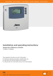
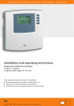
Installation and operating instructions
Temperature difference controller
6 inputs, 3 outputs,
integrated data logger for SD card
These operating instructions are part of the product.
Read these operating instructions carefully before use,
keep them over the entire lifetime of the product,
and pass them on to any future owner or user of this product.
EN
727.775 | Z02 | 08.10 | Subject to change due to technical improvements!
EN
Content
1
Safety....................................................................................4
1.1
1.2
Proper usage ............................................................................ 4
Dangers during assembly and commissioning......................... 4
1.3
Detecting faults ....................................................................... 5
1.4
1.5
Hot water temperature ............................................................ 5
Disposal ................................................................................... 5
1.6
Exclusion of liability ................................................................. 5
2
3
Case overview ......................................................................6
About this manual ...............................................................7
3.1
Applicability ............................................................................. 7
3.2
3.3
Users ........................................................................................ 7
Description of symbols ............................................................ 7
4
4.1
Installation ..........................................................................8
Opening/closing the housing ................................................... 8
4.2
4.3
4.4
Assembly.................................................................................. 9
Electrical connection .............................................................. 10
Dismantling............................................................................ 11
4.5
5
5.1
Terminal diagram .................................................................. 12
Commissioning...................................................................16
Setting the language ............................................................ 16
5.2
5.3
5.4
5.5
6
6.1
6.2
6.3
7
7.1
7.2
7.3
7.4
7.5
7.6
7.7
7.8
Setting the time and date ...................................................... 16
Setting the automatic summer time ...................................... 16
Setting the system group ................................................ 17
Setting the system ................................................................. 17
Modes of operation ...........................................................18
"OFF" mode ............................................................................ 18
"Automatic" mode .................................................................. 18
"Manual" mode ...................................................................... 18
Settings...............................................................................19
Time/date ............................................................................... 19
Systems .................................................................................. 22
Functions ............................................................................... 62
Parameters ............................................................................. 81
Storage priority ...................................................................... 83
Language ............................................................................... 84
Factory settings ...................................................................... 84
Set season ............................................................................. 84
2
727.775 | 08.10
EN
8
Automatic mode ................................................................85
8.1
8.2
Status display ......................................................................... 86
Temperature sensor min/max display ..................................... 86
8.3
9
Operating hours display for pumps and switching valves ..... 86
Data logger.........................................................................87
9.1
Handling the SD card ............................................................. 87
9.2
9.3
Display screen ........................................................................ 87
Formating .............................................................................. 88
9.4
Data evaluation...................................................................... 89
10
11
Service ................................................................................90
Fault finding .......................................................................90
11.1 Causes of problems ............................................................... 90
11.2 Pt1000 temperature sensor values......................................... 92
12 Information windows ........................................................93
13
Plausibility indices ..............................................................97
14
15
Legal guarantee .................................................................98
Technical data .....................................................................99
15.1 Performance data .................................................................. 99
15.2 Parameter settings ............................................................... 100
15.3 Parameter values for functions ........................................... 102
16
Notes ................................................................................107
Product information
EC declaration of conformity
"This product conforms to the applicable European directives with
regard to its design and its operating behaviour. This conformity has
been verified. Further information in this regard can be obtained from
your dealer."
727.775| 08.10
3
EN
1
Safety
1.1
Proper usage
The temperature difference controller (hereinafter referred to as controller) is an independently installed
electronic temperature controller for on-surface installation, and may only be used for controlling solar
thermal systems within the permissible ambient conditions (see chapter 15 "Technical data").
The controller must not be operated in the following environments:
• outdoors
• in damp rooms
• in rooms where highly flammable gas mixtures can occur
• in rooms in which the operation of electrical and electronic components may cause dangers to arise
1.2
Dangers during assembly and commissioning
The following dangers exist during installation/commissioning of the controller and during operation (in
case of installation errors):
• risk of death by electrocution
• risk of fire due to short-circuit
• damage to any of the constructional fire safety measures present in the building due to incorrectly
installed cables
• damage to the controller and the connected devices due to improper ambient conditions, inappropriate power supply and the connection of prohibited devices, faulty devices, or devices not included in
the device specifications, as well as incorrect assembly or installation
NOTE
Observe the controller's type plate!
Therefore, all safety regulations apply when working on the mains supply. Only electricians may perform
work that requires opening the controller (such as electrical connection work).
When laying cables, ensure that no damage occurs to any of the constructional fire safety measures
4
present in the building.
Make sure that the permissible ambient conditions at the installation site are not exceeded (see chapter 15 "Technical data").
Be sure to comply with the specified ingress protection.
Labels and markings applied in the factory may not be altered, removed or rendered unreadable.
Before connecting the device, make sure that the power supply matches the specifications on the type
plate.
Make sure that all devices which are connected to the controller conform to the technical data of the
controller.
Secure the device against unintentional start-up.
All work on an open controller must be performed with the mains supply removed.
Protect the controller against overloading and short-circuiting.
727.775 | 08.10
EN
1.3
Detecting faults
Check the display regularly.
In case of faults, isolate the cause (see chapter 11.1 "Causes of problems").
As soon as it becomes evident that safe operation is no longer guaranteed (e.g. visible damage),
remove the device from the mains supply immediately.
Have trained professional personnel remedy the fault.
1.4
Hot water temperature
In order to limit the hot water temperature to 60 °C at the outlets, a hot water mixer must be installed.
1.5
Disposal
Dispose of the controller in accordance with the regional regulations.
1.6
Exclusion of liability
The manufacturer can neither monitor the compliance with this manual nor the conditions and methods
during the installation, operation, usage and maintenance of the controller. Improper installation of the
system may result in damage to property and, as a result, to bodily injury.
Therefore, the manufacturer assumes no responsibility and liability for loss, damage or costs which result
from or are in any way related to incorrect installation, improper operation, incorrect execution of installation work and incorrect usage and maintenance.
Similarly, we assume no responsibility for patent right or other right infringements of third parties caused
by usage of this controller.
The manufacturer reserves the right to make changes to the product, technical data or installation and
operating instructions without prior notice.
727.775| 08.10
5
EN
2
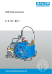
Case overview
Display
Display for controller operation
and system settings
Operating switch
The following modes of operation
can be selected:
Operating buttons
-
Manual
for commissioning
and testing for function
Arrow up
for scrolling up through the menus
-
Automatic
for automatic operation
-
Off
for switching off
the outputs
SET button
confirmation or activation of a value
ESC button
escape key
Arrow down
for scrolling down through the menus
Manual
Automatic
Off
SD card
Fuses
(see chapter 15)
Replacement fuses
(see chapter 15)
Power connection
Outputs
6
Inputs
Strain relief
RS232 and RS485 interface,
alarm output,
Direct Sensor output
727.775 | 08.10
EN
3
About this manual
3.1
Applicability
This manual describes the installation, commissioning, operation, maintenance and dismantling of the
temperature differential controller for solar thermal energy systems. When installing the remaining components, e.g. solar collectors, pump assemblies, storage units, pumps and switching valves, be sure to observe
the appropriate installation instructions provided by each manufacturer.
3.2
Users
Installation, commissioning, maintenance and dismantling of the controller may only be performed by
trained professional personnel. Before commissioning, the controller must be professionally assembled and
installed by professional personnel in accordance with the applicable regional and transregional regulations
as well as the safety instructions and general instructions within these installation and operating instructions. The professional personnel must be familiar with these operating instructions.
The controller is maintenance-free.
Use the controller only after first thoroughly reading and understanding these operating instructions and
the safety instructions. Adhere to all safety instructions and consult professional personnel in the event of
any ambiguities.
This device is not intended for persons (or children) with physical, sensory, or mental disabilities, or who
have inadequate experience and knowledge, unless they are instructed in the use of the device, and initially
supervised, by a person responsible for their safety. Children should not be left alone with the device, to
ensure that they do not play with it.
3.3
Description of symbols
3.3.1
The structure of the warning notices
SIGNAL WORD
Type, source and consequences of the danger!
Measures for avoiding danger.
3.3.2
Danger levels in warning notices
Danger level
DANGER
WARNING
CAUTION
CAUTION
3.3.3
Likelihood of occurrence
Consequences resulting
from non-compliance
Imminent threat of danger Death, serious bodily injury
Possible threat of danger
Death, serious bodily injury
Possible threat of danger
Minor bodily injury
Possible threat of danger
Property damage
Note
NOTE
Note on easier and safer working habits.
Measures for easier and safer working habits.
727.775| 08.10
7
EN
3.3.4
Other symbols and markings
Symbol
•
Emphasis on
issue at hand
:
:
Meaning
Condition for action
Call to action
Result of action
List
Emphasis on issue at hand
SET:
Press „Arrow up/down“ for scrolling.
Press „Arrow down“ for scrolling through the
menu or to adjust a value.
Press „Arrow up“ for scrolling through the menu
or to adjust a value.
Press „SET“ button to confirm or activate a value.
ESC:
Press „ESC“ button to cancel.
:
4
Installation
4.1
Opening/closing the housing
DANGER
Risk of death by electrocution!
Remove the controller from the power supply before opening the case.
Make sure that the power supply cannot be unintentionally switched
back on.
Do not damage the case.
Only switch the power supply back on after the case has been closed.
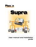
The upper case is connected to the lower case by two latches, and fastened with a screw.
4.1.1
Opening the case
Loosen the screw and remove the upper case in an upwards direc-
tion.
4.1.2
Closing the case
Place the upper case over the lower case at an angle. Insert the
latches into the recesses of the lower case.
Pivot the upper case down and feed the operating buttons through
the matching holes.
Fasten the case tightly with the screw.
Operating buttons
Latch
Upper casing
Lower case
8
Screw
727.775 | 08.10
EN
4.2
Assembly
WARNING
Risk of electrical shock and fire if mounted in a damp environment!
Only mount the controller in an area where the ingress protection is
sufficient (see chapter 15 "Technical data").
4.2.1
Mounting the controller
CAUTION
Risk of injury and damage to the case when drilling!
Do not use the case as a drilling template.
Choose a suitable installation site.
Drill the upper fastening hole.
Screw in the screw.
Remove the upper case.
Hang the case in the recess .
Mark the position of the lower fastening holes ,.
Remove the case again.
Drill the lower fastening holes.
Hang the case in recess .
Screw the case firmly using the lower fastening holes and .
Mount the upper case.
136
155
1
2
3
148
164
727.775| 08.10
9
EN
4.3
Electrical connection
DANGER
Risk of death by electrocution!
Remove the controller from the power supply before opening the
case.
Observe all applicable legal guidelines and regulations of the local
electricity supplier.
NOTE
The device is to be connected to the mains by means of a plug with
grounding contact, or in the case of a fixed electrical installation, via a
disconnection device for complete disconnection in accordance with the
installation guidelines.
4.3.1
Preparing the cable feed
Depending on how the controller is mounted, the cables may enter the
device through the rear of the case or the lower side of the case.
4
4
5
6
5
Feeding the cable through the rear of the case:
Remove the plastic flaps from the rear side of the case using an
appropriate tool.
WARNING
Risk of electrical shock and fire due to cables coming loose!
Install an external strain relief for the cables.
Feeding the cable through the lower side of the case:
Use an appropriate tool to cut the plastic flaps at the left and the
right and break them out of the case.
Fasten cable at position with the provided plastic links.
10
727.775 | 08.10
EN
4.3.2
Connecting the cables
If a protective conductor is provided or required for pumps/valves,
connect it to the corresponding terminals of the controller. When
connecting the protective conductor, observe the following points:
- Make sure that the protective conductor is also connected to the
controller's mains supply side.
- Each terminal may only be connected to a single connecting wire
(max 2.5 mm2).
The terminal screws are approved for connection of cables as follows:
- single wire (solid): ≤ 2.5 mm²
- fine strand (with core end sleeves): ≤ 1.5 mm²
Only use the original temperature sensors (Pt1000) that are
approved for use with the controller.
Observe the following points:
- The polarity of the temperature sensor contacts is not important.
- Do not lay sensor cables close to power cables
(minimum separation: 100 mm).
- If inductive effects are expected, e.g. from power cables,
overhead wires, transformer substations, radio and television
devices, amateur radio stations, microwave devices, etc., the
sensor cables must be adequately screened.
- Sensor cables may be extended to a maximum length of 100 m.
If adding extensions to sensor cables, select the following cable
cross sections:
- 0.75 mm2 up to 50 m long
- 1.5 mm2 up to 100 m long
Connect the cables in accordance with the terminal diagram
(see chapters 4.5 and 7.2)
4.4
Dismantling
DANGER
Risk of death by electrocution!
Remove the controller from the power supply before dismantling it.
To dismantle the controller, follow the assembly instructions in the
reverse order.
727.775| 08.10
11
EN
4.5
Terminal diagram
4.5.1
Power connection
• Please refer to the type plate on the case to determine the type of
power supply required
• The protective conductor must be connected
• Cables conforming to at least type H05 VV-... (NYM…) must be used
G1: grid
D1: wire bridge
G1
N
L
N
R1
N
R2
n.c.
N
L
n.c n.c. R3
L n.c. n.c.
X
230 V ~
115 V ~
D1
4.5.2
Connection of the inputs
• Inputs 1 - 5: for Pt1000 temperature sensor
E1
E2
E3
E4
E5
E6
1
2
3
4
5
6
T1
T2
T3
T4
T5
T6 *)
• Input 6: for Pt1000 temperature sensor or pulse generator for
recording volume flow (measuring heat quantities)
12
E1: input 1
E2: input 2
E3: input 3
E4: input 4
E5: input 5
E6: input 6
T6 *): T6 or pulse generator
727.775 | 08.10
EN
Inputs 1 - 5: temperature recording
Inputs
1...5
ϑ
T1...T5
Temperature sensor Pt 1000
(polarity irrelevant)
Input 6: recording temperatures and pulse values
Temperature
recording
6
ϑ
T6
Pt1000 temperature
sensor
(polarity irrelevant)
Recording pulse values
via reed relay
6
Standard:
volume flow recording
(polarity irrelevant)
727.775| 08.10
Recording pulse values
via open collector
6
Special case:
volume flow recording
(observe polarity,
pulse signals up to max.
600 Hz)
13
EN
4.5.3
Connection of outputs R1, R2 and R3
Outputs R1 and R2:
• Semiconductor relays (TRIAC), also suitable for RPM control; max.
switching current: see type plate
CAUTION
Avoiding damage and malfunctions
When connecting an external relay or contactor, or when connect-
ing a pump which has its own electronic RPM control, the controller
output's RPM control must be deactivated (see chapter 7.4.3 "Setting
the RPM control parameters").
R1
N
R1
R2
N
R1: output 1
R2: output 2
R3: output 3
D1: wire bridge
R3
R2
n.c.
N
L
n.c n.c. R3
L n.c. n.c.
X
R2
R1
D1
Output R3: switched output or potential-free
output
• 230 VAC switched output (option: 115 VAC) via electromechanical
relay; max. switching current: see type plate; wire bridge must be
connected!
R1
N
R1
R3
R2
N
R2
n.c.
R1: output 1
R2: output 2
R3: output 3
D1: wire bridge
N
L
n.c n.c. R3
L n.c. n.c. X
R3
D1
14
727.775 | 08.10
EN
• Potential-free output via electromechanical relay; wire bridge must
be removed!
DANGER
Risk of death by electrocution!
In the event of use as a potential-free output, it must be ensured that
the connections cannot come into contact with the mains voltage.
R1: output 1
R2: output 2
R3: output 3
R1
N
R2
R1
N
R3
R2
L
n.c n.c. R3
L n.c. n.c.
X
R3
n.c.
N
4.5.4
RS232 and RS485 interface, alarm output, and
Direct Sensor input
RS485 interface
B
Rx Tx
RS232 interface
A
Rx Tx
B
T
A
D - Sub
9-pin socket
(solder side)
T
1 2 3 4 5
6 7 8 9
Alarm output, see chapter 15
T
T
Direct Sensor
(observe the manufacturer’s
specifications)
727.775| 08.10
Q
T
T
5V
+
15
EN
5
Commissioning
Make sure that the installation is finished completely and correctly,
and that the switch on the controller is set to "OFF".
The display for setting the language appears.
5.1
Setting the language
"Deutsch" flashes in the display.
: select a language.
SET: confirm the language.
[..........]
ESC: finish the settings.
Display: 6.1
The display for setting the time appears.
5.2
[Deutsch]
Setting the time and date
"12:00" flashes in the display.
: set the hours.
SET: confirm the hours.
Display: 1.1
The minutes display flashes.
: set the minutes.
SET: confirm the minutes.
The year flashes.
: set the year.
SET: confirm the year.
The month flashes.
: set the month.
SET: confirm the month.
The day flashes.
: set the day.
SET: confirm the day.
ESC: finish the settings.
Display for activating the "automatic summer time change-over"
appears.
5.3
Setting the automatic summer time
Display for "automatic summer time change-over" appears.
NOTE
The controller can also be operated without activating the "automatic
summer time change-over".
SET: press button.
"automatic summer time change-over" is activated.
ESC: finish the settings.
The display for setting the system group appears.
16
727.775 | 08.10
⌧
Automatic
summer time
change-over
(for EU)
EN
5.4
Setting the system group
NOTE
For an overview of systems, see chapter 7.2 "Systems".
Display: 2.1
The first system group (1 storage tank system) appears in the
display.
[Storage tank]
: select a system group.
SET: confirm the system group.
The display for setting the system appears.
5.5
Setting the system
The first system in the selected system group appears in the display.
: selecting a system.
SET: confirm the system.
Display: 2.1.1
In the display, a small checkmark appears below the item
number, which confirms that the system is selected.
ESC: exit the settings menu.
The commissioning is finished.
727.775| 08.10
17
EN
6
Modes of operation
6.1
"OFF" mode
In order to switch off the outputs, slide the operating switch down.
A new window appears in the display, which shows "OFF", as
well as the controller software version number and the number
of the chosen system. The display is lit with a red background.
In "OFF" mode, all outputs (R1, R2, R3) are switched off.
off
NOTE
On delivery from the manufacturer, the switch is set to "OFF".
6.2
"Automatic" mode
CAUTION
Damage to pump caused by dry operation!
The controller may only be set to "Automatic" when the system has been
filled.
In order to switch the outputs to "Automatic", slide the operating
switch to the middle position.
The status appears in the display.
This mode of operation is the automatic controller mode and must be
set for automatic operation.
Automatic
NOTE
During normal system operation, the operating switch should always
be set to "Automatic".
6.3
"Manual" mode
CAUTION
Damage to pump caused by dry operation!
The controller may only be set to "Manual" when the system has been
filled.
When operating the device for the first time, or when testing the function, the controller outputs can be manually switched.
In order to switch the outputs manually, slide the operating switch up.
The display is backlit in red and a settings window is displayed.
: selecting an output.
SET: switch the selected output to "on" or "off".
ESC: close the settings window.
The current recorded values can now also be queried for the
purpose of checking.
: access measured values.
SET: reopen the settings window.
18
727.775 | 08.10
!!
!!
Manual
EN
7
Settings
Menu overview, see following double page
7.1
The time and date can be displayed and adjusted via the "Time/Date"
menu item. The automatic summer time change-over can still be activated or deactivated.
7.1.1
Display: 1
Time/date
Setting the time and date
SET: press button for approx. 2 sec.
[Time/date]
The "Time" menu item is displayed.
SET: press button.
The current time is displayed.
SET: press button to confirm.
The hours display flashes after confirmation of the time.
: set the hours.
SET: press button to confirm.
Display: 1.1
The minutes display flashes after confirmation of the hours.
: set the minutes.
SET: press button to confirm.
The year display flashes after confirmation of the minutes.
: set the year.
SET: press button to confirm.
The month display flashes after confirmation of the year.
: set the month.
SET: press button to confirm.
The day display flashes after confirmation of the month.
: set the day.
SET: confirm the time and date.
7.1.2
Activating the automatic summer time
change-over
: press button.
⌧
Automatic
summer time
change-over
(for EU)
The display for “Automatic summer time change-over (for EU)”
appears.
SET: press to activate or deactivate the automatic summer time
change-over.
A cross in the control box shows that the automatic summer
time change-over is active.
ESC: exit the "automatic summer time change-over" submenu.
ESC: exit the "Time/Date" menu item.
NOTE
The controller can also be operated without activating the "automatic
summer time change-over".
727.775| 08.10
19
EN
Menu overview
SET 2 sec
ESC
Status display
Set season
The menu item “Set
season” is only
displayed if a
seasonal system
has been selected.
Time
Systems
1 storage tank
systems
2 storage tanks
systems
3 storage tanks
systems
Swimming pool
systems
S torage tank swimming pool systems
System 1
System 12
System 21
System 23
System 29
System 2
System 13
System 22
System 24
System 30
System 3
System 14
System 25
System 31
System 4
System 15
System 26
System 32
System 5
System 16
System 27
System 6
System 17
System 28
System 7
System 18
System 8
System 19
System 9
System 20
System 10
System 11
20
727.775 | 08.10
EN
Functions
Parameters
2 storage tanks swimming pool systems
Seasonal systems
Circulation
Max. temperature
storage tank 1
System 33
System 35
Back-up heating
Max. temperature
storage tank 2
System 34
System 36
Solid fuel boiler
Max. temperature
storage tank 3
System 37
Quick charge
Max. temperature
swimming pool
System 38
Bypass
System 39
Heat quantity
System 40
Thermostat
Difference
thermostat
Storage priority
Language
Factory
settings
Switch-on temp.
difference solar 1
Switch-off temp.
difference solar 1
Switch-on temp.
difference solar 2
Time function
Interval
Switch-off temp.
difference solar 2
Stagnation
reduction
Max. collector
temperature
Holiday/recooling
function
Min. collector
temperature
Frost protection
Switch-on temperature difference
return increase
Anti-legionella
function
Display storage
tank top
Switch-off temperature difference
return increase
Data logger
Max. temperature
loading circuit 1
Alarm output
Min. temperature
loading circuit 1
Max. temperature
loading circuit 2
Min. temperature
loading circuit 2
Loading strategy
storage tank 1
Loading strategy
storage tank 2
Loading strategy
storage tank 3
RPM control
pump R1
RPM control
pump R2
727.775| 08.10
21
EN
7.2
Systems
The desired solar energy system can be chosen using the "Systems" submenu. There are a total of 40
different systems to choose from (subdivided into 7 system groups).
System group
40 systems
Chapter
Systems with one
storage tank
System 1: 1 collector array – 1 storage tank
7.2.1
System 2: 1 collector array – 1 storage tank – heating return increase
System 3: 1 collector array – 1 storage tank with external heat
exchanger
System 4: 1 collector array – 1 storage tank with external heat
exchanger – heating return increase
System 5: 1 collector array – 1 storage tank with zone loading
System 6: 1 collector array – 1 storage tank with zone loading
– heating return increase
System 7: 1 collector array – 1 storage tank with zone loading
and external heat exchanger
System 8: 2 collector arrays (east/west roof) – 1 storage tank
System 9: 2 collector arrays (east/west roof) – 1 storage tank
- heating return increase
System 10: 2 collector arrays (east/west roof) - 1 storage tank
with external heat exchanger
System 11: 2 collector arrays (east/west roof) – 1 storage tank
with zone loading
Systems with two
storage tanks
System 12: 1 collector array – 2 storage tanks – intelligent pump
control
System 13: 1 collector array – 2 storage tanks – heating return
increase – intelligent pump control
System 14: 1 collector array – 2 storage tanks – intelligent valve
control
System 15: 1 collector array – 2 storage tanks – heating return
increase – intelligent valve control
System 16: 1 collector array – 1 storage tank – 1 storage tank with
external heat exchanger – intelligent pump control
System 17: 1 collector array – 1 storage tank –1 storage tank with
external heat exchanger – intelligent valve control
System 18: 1 collector array – 2 storage tanks with external heat
exchanger – intelligent pump control
System 19: 1 collector array – 2 storage tanks with external heat
exchanger – intelligent valve control
System 20: 2 collector arrays (east/west roof) – 2 storage tanks
22
727.775 | 08.10
7.2.2
EN
System group
40 systems
Chapter
Systems with three
storage tanks
System 21: 1 collector array – 3 storage tanks – intelligent pump
control
System 22: 1 collector array – 3 storage tanks – intelligent valve
control
7.2.3
Systems with a
swimming pool
System 23: 1 collector array – 1 swimming pool
7.2.4
System 24: 1 collector array – 1 swimming pool with external
heat exchanger
System 25: 1 collector array – 1 swimming pool in stand-alone
operation with external heat exchanger
System 26: 2 collector arrays (east/west roof) – 1 swimming pool
System 27: 2 collector arrays (east/west roof) - 1 swimming pool
with external heat exchanger
System 28: 2 collector arrays (east/west roof) – 1 swimming pool
in stand-alone operation with external heat exchanger
Systems with one
storage tank and a
swimming pool
System 29: 1 collector array – 1 storage tank – 1 swimming pool
7.2.5
with external heat exchanger – intelligent pump control
System 30: 1 collector array – 1 storage tank – 1 swimming pool
with external heat exchanger – intelligent valve control
System 31: 1 collector array – 1 storage tank – 1 swimming pool
in stand-alone operation with external heat exchanger
– intelligent pump control
System 32: 1 collector array – 1 storage tank – 1 swimming pool
in stand-alone operation with external heat exchanger
– intelligent valve control
Systems with two
System 33: 1 collector array – 2 storage tanks – 1 swimming pool 7.2.6
in stand-alone operation with external heat exchanger
storage tanks and a
– intelligent pump control
swimming pool
System 34: 1 collector array – 2 storage tanks – 1 swimming pool
in stand-alone operation with external heat exchanger
– intelligent valve control
Seasonal systems
System 35: 1 collector array – 1 storage tank – 1 swimming pool
7.2.7
with external heat exchanger – intelligent pump control
System 36: 1 collector array – 1 storage tank – 1 swimming pool
with external heat exchanger – intelligent valve control
System 37: 1 collector array – 1 storage tank – 1 swimming pool
in stand-alone operation with external heat exchanger
– intelligent pump control
System 38: 1 collector array – 1 storage tank – 1 swimming pool
in stand-alone operation with external heat exchanger
– intelligent valve control
System 39: 1 collector array – 2 storage tanks – 1 swimming pool
in stand-alone operation with external heat exchanger
– intelligent pump control
System 40: 1 collector array – 2 storage tanks – 1 swimming pool
in stand-alone operation with external heat exchanger
– intelligent valve control
727.775| 08.10
23
EN
NOTE
Upon selection of a new system, the functions, storage tank priority, and
parameters are automatically returned to their factory settings.
Check the settings again!
Selecting a system
SET: press button for approx. 2 sec.
: select the menu item "Systems".
Display: 2
SET: open the submenu "System groups".
[Systems]
: select a system group.
SET: press button to confirm.
: selecting a system.
SET: press button to confirm.
In the display, a small checkmark appears below the item
number, which confirms that the system is selected.
ESC: exit the "Systems" menu item.
Display example
Display example
24
727.775 | 08.10
EN
Systems with one storage tank
System 1: 1 collector array – 1 storage tank
Description of the solar function: the solar circuit pump R1 is switched
on as soon as the switch-on temperature difference between the collector array A1 (T1) and the storage tank B1 (T2) is reached. When the
switch-off temperature difference between the collector array A1 (T1)
and the storage tank B1 (T2) or a safety limit is reached, the solar circuit
pump R1 is switched off again.
Display: 2.1
[Storage tank]
Display: 2.1.1
7.2.1
Loading strategy of solar circuit pump R1: in the factory, temperature
differential control is chosen as the loading strategy for the storage tank
B1. It can be adjusted or changed to target temperature control using
the "Parameters" menu (chapter 7.4 "Parameters").
Activating the system: see chapter 7.2 "Selecting a system".
Terminal layout
L
N
R1
N
N
R2
n.c.
L
n.c. n.c.
L
R3
n.c. n.c.
1
D1
T1
R1
2
3
4
5
6
X
T2
N
230 V~
115 V~
A1: collector array
B1: storage tank
D1: wire bridge
R1: solar circuit pump
T1: collector sensor
T2: sensor at bottom of
storage tank
T1
B1
A1
T2 T2
R1
727.775| 08.10
25
EN
System 2: 1 collector array – 1 storage tank –
heating return increase
Description of the solar function: the solar circuit pump R1 is switched
on as soon as the switch-on temperature difference between the collector array A1 (T1) and the storage tank B1 (T2) is reached. When the
switch-off temperature difference between the collector array A1 (T1)
and the storage tank B1 (T2) or a safety limit is reached, the solar circuit
pump R1 is switched off again.
Display: 2.1.2
Description of the heating return increase: the 3-way valve R2 in the
heating return is switched on (water flows through storage tank) as
soon as the switch-on temperature difference between the storage tank
B1 (T3) and the heating return (T4) is reached. When the switch-off temperature difference (T3 – T4) is reached, the 3-way valve R2 returns to its
initial state. Water does not flow through the storage tank.
NOTE
When no voltage is on the system, the switching valve R2 must be set in
such a manner that water does not flow through the storage tank.
Loading strategy of solar circuit pump R1: in the factory, temperature
differential control is chosen as the loading strategy for the storage tank
B1. It can be adjusted or changed to target temperature control using
the "Parameters" menu (chapter 7.4 "Parameters").
Activating the system: see chapter 7.2 "Selecting a system".
R1
N
L
n.c. n.c.
L
R3
n.c. n.c.
1
2
3
4
5
A1: collector array
B1: storage tank
D1: wire bridge
R1: solar circuit pump
R2: switching valve
heating return increase
T1: collector sensor
T2: sensor at bottom of storage
tank
T3: heating return increase
storage tank sensor
T4: heating return sensor
6
X
D1
R2
R1
n.c.
230 V~
115 V~
N
R2
T4
N
T2
L
T1
N
T3
Terminal layout
T1
B1
A1
T3
T4
T2
R1
26
R2
727.775 | 08.10
EN
Display: 2.1.3
System 3: 1 collector array –
1 storage tank with external heat exchanger
Description of the solar function: the solar circuit pump R2 is switched
on as soon as the switch-on temperature difference between the collector array A1 (T1) and the storage tank B1 (T2) is reached. When the
switch-off temperature difference or a safety limit is reached, the solar
circuit pump R2 switches off. The storage tank loading pump R1 is
switched on as soon as the switch-on temperature difference between
the external heat exchanger F1 (T3) and the storage tank B1 (T2) is
reached. The storage tank is loaded until the switch-off temperature
difference between the external heat exchanger F1 (T3) and the storage
tank B1 (T2) is reached, or until a safety limit is reached.
Loading strategy of storage tank loading pump R1 and solar circuit
pump R2: in the factory, target temperature control is chosen as the
loading strategy for the storage tank B1. It can be adjusted or changed
using the "Parameters" menu (chapter 7.4 "Parameters").
Activating the system: see chapter 7.2 "Selecting a system".
Terminal layout
R1
N
N
R2
L
n.c. n.c.
L
R1
R3
n.c. n.c.
D1
R2
n.c.
1
2
3
4
5
6
X
T3
N
T1
L
T2
N
230 V~
115 V~
A1: collector array
B1: storage tank
D1: wire bridge
F1: external heat exchanger
R1: storage tank loading
pump
R2: solar circuit pump
T1: collector sensor
T2: sensor at bottom of
storage tank
T3: external heat exchanger
sensor
T1
A1
B1
F1 T3
T2
R2
727.775| 08.10
R1
27
EN
System 4: 1 collector array – 1 storage tank with external heat exchanger – heating return increase
Description of the solar function: the solar circuit pump R2 is switched
on as soon as the switch-on temperature difference between the collector array A1 (T1) and the storage tank B1 (T2) is reached. When the
switch-off temperature difference or a safety limit is reached, the solar
circuit pump R2 switches off. The storage tank loading pump R1 is
switched on as soon as the switch-on temperature difference between
the external heat exchanger F1 (T4) and the storage tank B1 (T2) is
reached. The storage tank is loaded until the switch-off temperature
difference between the external heat exchanger F1 (T4) and the storage
tank B1 (T2) is reached, or until a safety limit is reached.
Display: 2.1.4
Description of the heating return increase: the 3-way valve R3 in the
heating return is switched on (water flows through storage tank) as
soon as the switch-on temperature difference between the storage tank
B1 (T3) and the heating return (T5) is reached. When the switch-off temperature difference (T3 – T5) is reached, the 3-way valve R3 returns to its
initial state. Water does not flow through the storage tank.
NOTE
When no voltage is on the system, the switching valve R3 must be set in
such a manner that water does not flow through the storage tank.
Loading strategy of storage tank loading pump R1 and solar circuit
pump R2: in the factory, target temperature control is chosen as the
loading strategy for the storage tank B1. It can be adjusted or changed
using the "Parameters" menu (chapter 7.4 "Parameters").
Activating the system: see chapter 7.2 "Selecting a system".
n.c.
L
n.c. n.c.
L
R3
n.c. n.c.
1
2
R2
3
4
5
A1: collector array
B1: storage tank
D1: wire bridge
F1: external heat exchanger
R1: storage tank loading pump
R2: solar circuit pump
R3: heating return increase
switching valve
T1: collector sensor
T2: sensor at bottom of storage
tank
T3: heating return increase
storage tank sensor
T4: external heat exchanger
sensor
T5: heating return sensor
6
X
D1
R1
230 V~
115 V~
N
R2
T4
N
T5
R1
T2
N
T1
L
R3
N
T3
Terminal layout
T1
A1
B1
T3
F1 T4
T2
R2
28
R1
T5
R3
727.775 | 08.10
EN
Display: 2.1.5
System 5: 1 collector array – 1 storage tank with zone
loading
Description of the solar function: the solar circuit pump R1 is switched
on as soon as the switch-on temperature difference between the collector array A1 (T1) and the storage tank B1 (T2) is reached. When the
switch-off temperature difference between the collector array A1 (T1)
and the storage tank B1 (T2) or a safety limit is reached, the solar circuit
pump R1 is switched off again.
Description of the zone loading: the zone loading valve R2 is switched
on (loading of the upper storage tank zone) as soon as the temperature
difference between the collector array A1 (T1) and the upper loading
zone (T3) has reached the switch-on temperature difference. When the
switch-off temperature difference or a safety limit is reached, or the solar
circuit pump R1 is switched off, the zone loading valve R2 switches off.
NOTE
When no voltage is on the system, the switching valve R2 must be set to
the lower loading zone (T2).
Loading strategy of solar circuit pump R1: in the factory, target temperature control is chosen as the loading strategy for the storage tank
B1. It can be adjusted or changed using the "Parameters" menu (chapter
7.4 "Parameters").
Activating the system: see chapter 7.2 "Selecting a system".
Terminal layout
R1
N
N
R2
n.c.
L
n.c. n.c.
L
R3
n.c. n.c.
1
D1
R2
R1
2
3
4
5
6
X
T2
N
T3
L
T1
N
230 V~
115 V~
A1: collector array
B1: storage tank
D1: wire bridge
R1: solar circuit pump
R2: zone loading
switching valve
T1: collector sensor
T2: sensor at bottom of storage
tank
T3: storage tank
zone loading sensor
T1
B1
A1
T3
R2
T2
R1
727.775| 08.10
29
EN
System 6: 1 collector array – 1 storage tank with zone
loading – heating return increase
Description of the solar function: the solar circuit pump R1 is switched
on as soon as the switch-on temperature difference between the collector array A1 (T1) and the storage tank B1 (T2) is reached. When the
switch-off temperature difference between the collector array A1 (T1)
and the storage tank B1 (T2) or a safety limit is reached, the solar circuit
pump R1 is switched off again.
Display: 2.1.6
Description of the zone loading: the zone loading valve R2 is switched
on (loading of the upper storage tank zone) as soon as the temperature
difference between the collector array A1 (T1) and the upper loading zone
(T3) has reached the switch-on temperature difference. When the switchoff temperature difference or a safety limit is reached, or the solar circuit
pump R1 is switched off, the zone loading valve R2 switches off.
Description of the heating return increase: the 3-way valve R3 in the
heating return is switched on (water flows through storage tank) as
soon as the switch-on temperature difference between the storage tank
B1 (T4) and the heating return (T5) is reached. When the switch-off temperature difference (T4 – T5) is reached, the 3-way valve R3 returns to its
initial state. Water does not flow through the storage tank.
NOTE
When no voltage is on the system, the switching valve R2 must be set
to the lower loading zone (T2).
When no voltage is on the system, the switching valve R3 must be set in
such a manner that water does not flow through the storage tank.
Loading strategy of solar circuit pump R1: in the factory, target temperature control is chosen as the loading strategy for the storage tank
B1. It can be adjusted or changed using the "Parameters" menu (chapter
7.4 "Parameters").
Activating the system: see chapter 7.2 "Selecting a system".
n.c.
L
n.c. n.c.
L
R3
n.c. n.c.
1
R2
2
4
5
3
A1: collector array
B1: storage tank
D1: wire bridge
R1: solar circuit pump
R2: zone loading
switching valve
R3: heating return increase
switching valve
T1: collector sensor
T2: sensor at bottom of storage
tank
T3: storage tank
zone loading sensor
T4: heating return increase
storage tank sensor
T5: heating return sensor
6
X
D1
R1
230 V~
115 V~
N
R2
T5
N
T2
R1
T3
N
T1
L
R3
N
T4
Terminal layout
T1
B1
A1
T3
T4
R2
T2
R1
30
T5
R3
727.775 | 08.10
EN
Display: 2.1.7
System 7: 1 collector array – 1 storage tank with zone
loading and external heat exchanger
Description of the solar function: the solar circuit pump R2 is switched
on as soon as the switch-on temperature difference between the collector array A1 (T1) and the storage tank B1 (T2) is reached. When the
switch-off temperature difference or a safety limit is reached, the solar
circuit pump R2 switches off. The storage tank loading pump R1 is
switched on as soon as the switch-on temperature difference between
the external heat exchanger F1 (T4) and the storage tank B1 (T2) is
reached. The storage tank is loaded until the switch-off temperature
difference between the external heat exchanger F1 (T4) and the storage
tank B1 (T2) is reached, or until a safety limit is reached.
Description of the zone loading: the zone loading valve R3 is switched
on (loading of the upper storage tank zone) as soon as the temperature
difference between the external heat exchanger F1 (T4) and the upper
loading zone (T3) has reached the switch-on temperature difference.
When the switch-off temperature difference or a safety limit is reached,
or the storage tank loading pump R1 is switched off, the zone loading
valve R3 switches off.
NOTE
When no voltage is on the system, the switching valve R3 must be set to
the lower loading zone (T2).
Loading strategy of storage tank loading pump R1 and solar circuit
pump R2: in the factory, target temperature control is chosen as the
loading strategy for the storage tank B1. It can be adjusted or changed
using the "Parameters" menu (chapter 7.4 "Parameters").
Activating the system: see chapter 7.2 "Selecting a system".
N
N
R2
n.c.
L
n.c. n.c.
L
R3
n.c. n.c.
1
2
R2
4
5
6
X
D1
R1
3
T4
R1
T2
N
T1
L
R3
N
230 V~
115 V~
A1: collector array
B1: storage tank
D1: wire bridge
F1: external heat exchanger
R1: storage tank loading pump
R2: solar circuit pump
R3: zone loading
switching valve
T1: collector sensor
T2: sensor at bottom of storage
tank
T3: storage tank
zone loading sensor
T4: external heat exchanger
sensor
T3
Terminal layout
T1
A1
B1
F1 T4
R3
T3
T2
R2
727.775| 08.10
R1
31
EN
System 8: 2 collector arrays (east/west roof) –
1 storage tank
Description of the solar function: when the switch-on temperature
difference between the storage tank B1 (T3) and one or the other of the
collector arrays A1, A2 (T1, T2) is reached, then either solar circuit pump
R1 for collector array A1 (T1), or solar circuit pump R2 for collector array
A2 (T2) is switched on, depending on where the temperature difference
occurs. When the switch-on temperature difference is reached for both
collector arrays A1, A2 (T1, T2), then both pumps R1, R2 are switched
on. When the switch-off temperature difference between the collector
array A1, A2 (T1, T2) and the storage tank B1 (T3) or a safety limit is
reached, the solar circuit pumps R1, R2 are switched off again.
Display: 2.1.8
Loading strategy of solar circuit pumps R1 and R2: in the factory,
temperature differential control is chosen as the loading strategy for the
storage tank B1. It can be adjusted or changed to target temperature
control using the "Parameters" menu (chapter 7.4 "Parameters").
Activating the system: see chapter 7.2 "Selecting a system".
Terminal layout
R1
N
L
n.c. n.c.
L
R3
n.c. n.c.
1
2
3
4
5
A1: collector array 1
A2: collector array 2
B1: storage tank
D1: wire bridge
R1: solar circuit pump 1
R2: solar circuit pump 2
T1: collector sensor 1
T2: collector sensor 2
T3: sensor at bottom of storage
tank
6
X
D1
R2
R1
n.c.
230 V~
115 V~
N
R2
T2
N
T3
L
T1
N
T1 T2
A1
A2
B1
R1
R2 T3
T3
32
727.775 | 08.10
EN
Display: 2.1.9
System 9: 2 collector arrays (east/west roof) –
1 storage tank – heating return increase
Description of the solar function: when the switch-on temperature
difference between the storage tank B1 (T3) and one or the other of the
collector arrays A1, A2 (T1, T2) is reached, then either solar circuit pump
R1 for collector array A1 (T1), or solar circuit pump R2 for collector array
A2 (T2) is switched on, depending on where the temperature difference
occurs. When the switch-on temperature difference is reached for both
collector arrays A1, A2 (T1, T2), then both pumps R1, R2 are switched
on. When the switch-off temperature difference between the collector
array A1, A2 (T1, T2) and the storage tank B1 (T3) or a safety limit is
reached, the solar circuit pumps R1, R2 are switched off again.
Description of the heating return increase: the 3-way valve R3 in the
heating return is switched on (water flows through storage tank) as
soon as the switch-on temperature difference between the storage tank
B1 (T4) and the heating return (T5) is reached. When the switch-off temperature difference (T4 – T5) is reached, the 3-way valve R3 returns to its
initial state. Water does not flow through the storage tank.
NOTE
When no voltage is on the system, the switching valve R3 must be set in
such a manner that water does not flow through the storage tank.
Loading strategy of solar circuit pumps R1 and R2: in the factory,
temperature differential control is chosen as the loading strategy for the
storage tank B1. It can be adjusted or changed to target temperature
control using the "Parameters" menu (chapter 7.4 "Parameters").
Activating the system: see chapter 7.2 "Selecting a system".
N
R2
n.c.
L
n.c. n.c.
L
R3
n.c. n.c.
1
R2
3
4
5
6
X
D1
R1
2
T5
N
T4
R1
T2
N
T1
L
R3
N
230 V~
115 V~
A1: collector array 1
A2: collector array 2
B1: storage tank
D1: wire bridge
R1: solar circuit pump 1
R2: solar circuit pump 2
R3: heating return increase
switching valve
T1: collector sensor 1
T2: collector sensor 2
T3: sensor at bottom of storage
tank
T4: heating return increase
storage tank sensor
T5: heating return sensor
T3
Terminal layout
T1 T2
A1
A2
B1
T4
T2 T2
R1
R2 T3
T3
T5
R3
727.775| 08.10
33
EN
System 10: 2 collector arrays (east/west roof) –
1 storage tank with external heat exchanger
Description of the solar function: when the switch-on temperature
difference between the storage tank B1 (T3) and one or the other of the
collector arrays A1, A2 (T1, T2) is reached, then either solar circuit pump
R1 for collector array A1 (T1), or solar circuit pump R3 for collector array
A2 (T2) is switched on, depending on where the temperature difference
occurs. When the switch-on temperature difference is reached for both
collector arrays A1, A2 (T1, T2), then both pumps R2, R3 are switched
on. When the switch-off temperature difference between the collector
array A1, A2 (T1, T2) and the storage tank B1 (T3) or a safety limit is
reached, the solar circuit pumps R2, R3 are switched off again.
Display: 2.1.10
The storage tank loading pump R1 is switched on as soon as the switchon temperature difference between the external heat exchanger F1
(T4) and the storage tank B1 (T3) is reached. The storage tank is loaded
until the switch-off temperature difference between the external heat
exchanger F1 (T4) and the storage tank B1 (T3) is reached, or until a
safety limit is reached.
Loading strategy of storage tank loading pump R1 and solar circuit
pump R2: in the factory, target temperature control is chosen as the
loading strategy for the storage tank B1. It can be adjusted or changed
using the "Parameters" menu (chapter 7.4 "Parameters").
Loading strategy of solar circuit pump R3: it is not possible to select
whether temperature differential control or target temperature control
is to be used as the loading strategy. Solar circuit pump R3 operates
according to the switch-on and switch-off temperature difference
parameter values.
Activating the system: see chapter 7.2 "Selecting a system".
N
n.c.
L
n.c. n.c.
L
R3
1
R2
2
3
4
5
A1: collector array 1
A2: collector array 2
B1: storage tank
D1: wire bridge
F1: external heat exchanger
R1: storage tank loading pump
R2: solar circuit pump 1
R3: solar circuit pump 2
T1: collector sensor 1
T2: collector sensor 2
T3: sensor at bottom of storage
tank
T4: external heat exchanger
sensor
6
X
n.c. n.c.
D1
R1
230 V~
115 V~
N
R2
T4
R1
T2
N
T1
L
R3
N
T3
Terminal layout
T1 T2
A1
A2
B1
T2 T2
R2
R3
F1 T4
T3
R1
34
727.775 | 08.10
EN
Display: 2.1.11
System 11: 2 collector arrays (east/west roof) –
1 storage tank with zone loading
Description of the solar function: when the switch-on temperature
difference between the storage tank B1 (T3) and one or the other of the
collector arrays A1, A2 (T1, T2) is reached, then either solar circuit pump
R1 for collector array A1 (T1), or solar circuit pump R2 for collector array
A2 (T2) is switched on, depending on where the temperature difference
occurs. When the switch-on temperature difference is reached for both
collector arrays A1, A2 (T1, T2), then both pumps R1, R2 are switched
on. When the switch-off temperature difference between the collector
array A1, A2 (T1, T2) and the storage tank B1 (T3) or a safety limit is
reached, the solar circuit pumps R1, R2 are switched off again.
Description of the zone loading: the zone loading valve R3 is switched
on (loading of the upper storage tank zone) as soon as the temperature
difference between the collector array A1, A2 (T1, T2) and the upper
loading zone (T4) has reached the switch-on temperature difference.
When the switch-off temperature difference or a safety limit is reached,
or the solar circuit pump R1, R2 is switched off, the zone loading valve
R3 switches off.
NOTE
When no voltage is on the system, the switching valve R3 must be set to
the lower loading zone (T3).
Loading strategy of solar circuit pumps R1 and R2: in the factory,
target temperature control is chosen as the loading strategy for the storage tank B1. It can be adjusted or changed using the "Parameters" menu
(chapter 7.4 "Parameters").
Activating the system: see chapter 7.2 "Selecting a system".
N
N
R2
n.c.
L
n.c. n.c.
L
R3
n.c. n.c.
R1
R2
D1
1
2
3
4
T4
R1
5
6
X
T2
N
T1
L
R3
N
230 V~
115 V~
A1: collector array 1
A2: collector array 2
B1: storage tank
D1: wire bridge
R1: solar circuit pump 1
R2: solar circuit pump 2
R3: zone loading
switching valve
T1: collector sensor 1
T2: collector sensor 2
T3: sensor at bottom of storage
tank
T4: storage tank
zone loading sensor
T3
Terminal layout
T1 T2
A1
A2
B1
T2 T2
R1
T4
R2 T3 R3
T3
727.775| 08.10
35
EN
7.2.2
System with two storage tanks
System 12: 1 collector array – 2 storage tanks –
intelligent pump control
Description of the solar function: when the switch-on temperature
difference between the collector array A1 (T1) and one of the two storage tanks B1, B2 (T2, T3) is reached, the appropriate solar circuit pump
R1 or R2 is switched on. Both storage tanks B1, B2 are loaded one after
the other, according to the priority control (chapter 7.5 "Storage tank
priority"), until either the relevant switch-off temperature difference
between the collector array A1 (T1) and storage tanks B1, B2 (T2, T3) is
reached, or a safety limit is reached.
Loading strategy of solar circuit pumps R1 and R2: in the factory,
temperature differential control is chosen as the loading strategy for the
storage tanks B1, B2. It can be adjusted or changed to target temperature control using the "Parameters" menu (chapter 7.4 "Parameters").
Display: 2.2
[Storage tank]
Display: 2.2.1
Activating the system: see chapter 7.2 "Selecting a system".
Terminal layout
R1
N
L
n.c. n.c.
L
R3
n.c. n.c.
1
2
3
4
5
6
A1: collector array
B1: storage tank 1
B2: storage tank 2
D1: wire bridge
R1: solar circuit pump 1
R2: solar circuit pump 2
T1: collector sensor
T2: sensor at bottom of storage
tank 1
T3: sensor at bottom of storage
tank 2
X
D1
R2
R1
n.c.
230 V~
115 V~
N
R2
T2
N
T3
L
T1
N
T1
B1
A1
B2
R1
R2
36
T2
T3
727.775 | 08.10
EN
Display: 2.2.2
System 13: 1 collector array – 2 storage tanks – heating
return increase – intelligent pump control
Description of the solar function: when the switch-on temperature
difference between the collector array A1 (T1) and one of the two storage tanks B1, B2 (T2, T3) is reached, the appropriate solar circuit pump
R1 or R2 is switched on. Both storage tanks B1, B2 are loaded one after
the other, according to the priority control (chapter 7.5 "Storage tank
priority"), until either the relevant switch-off temperature difference
between the collector array A1 (T1) and storage tanks B1, B2 (T2, T3) is
reached, or a safety limit is reached.
Description of the heating return increase: the 3-way valve R3 in the
heating return is switched on (water flows through storage tank) as
soon as the switch-on temperature difference between the storage tank
B2 (T4) and the heating return (T5) is reached. When the switch-off temperature difference (T4 – T5) is reached, the 3-way valve R3 returns to its
initial state. Water does not flow through the storage tank.
NOTE
When no voltage is on the system, the switching valve R3 must be set in
such a manner that water does not flow through the storage tank.
Loading strategy of solar circuit pumps R1 and R2: in the factory,
temperature differential control is chosen as the loading strategy for the
storage tanks B1, B2. It can be adjusted or changed to target temperature control using the "Parameters" menu (chapter 7.4 "Parameters").
Activating the system: see chapter 7.2 "Selecting a system".
N
R2
n.c.
L
R3
n.c. n.c.
L
n.c. n.c.
1
2
3
4
T4
N
R2
D1
R1
5
6
X
T5
R1
T3
N
T1
L
R3
N
230 V~
115 V~
A1: collector array
B1: storage tank 1
B2: storage tank 2
D1: wire bridge
R1: solar circuit pump 1
R2: solar circuit pump 2
R3: heating return increase
switching valve
T1: collector sensor
T2: sensor at bottom of storage
tank 1
T3: sensor at bottom of storage
tank 2
T4: heating return increase
storage tank sensor
T5: heating return sensor
T2
Terminal layout
T1
B1
A1
B2
T4
R1
R2
T2
T3
T5
R3
727.775| 08.10
37
EN
System 14: 1 collector array – 2 storage tanks –
intelligent valve control
Description of the solar function: when the switch-on temperature difference between the collector array A1 (T1) and one of the two storage
tanks B1, B2 (T2, T3) is exceeded, the solar circuit pump R1 is switched
on and the switching valve R2 is set to the correct position depending on
the storage tank to be loaded. Both storage tanks B1, B2 are loaded one
after the other, according to the priority control (chapter 7.5 "Storage
tank priority"), until either the relevant switch-off temperature difference between the collector array A1 (T1) and storage tanks B1, B2 (T2,
T3) is reached, or a safety limit is reached.
Display: 2.2.3
NOTE
When no voltage is on the system, the switching valve R2 must be set
to storage tank B1.
Loading strategy of solar circuit pump R1: in the factory, temperature differential control is chosen as the loading strategy for the storage
tanks B1, B2. It can be adjusted or changed to target temperature control using the "Parameters" menu (chapter 7.4 "Parameters").
Activating the system: see chapter 7.2 "Selecting a system".
Terminal layout
R1
N
L
n.c. n.c.
L
R1
R3
n.c. n.c.
1
2
3
4
5
A1: collector array
B1: storage tank 1
B2: storage tank 2
D1: wire bridge
R1: solar circuit pump
R2: switching valve
T1: collector sensor
T2: sensor at bottom of storage
tank 1
T3: sensor at bottom of storage
tank 2
6
X
D1
R2
n.c.
230 V~
115 V~
N
R2
T2
N
T3
L
T1
N
T1
B1
A1
B2
T2
R1
R2
T3
38
727.775 | 08.10
EN
Display: 2.2.4
System 15: 1 collector array – 2 storage tanks – heating
return increase – intelligent valve control
Description of the solar function: when the switch-on temperature difference between the collector array A1 (T1) and one of the two storage
tanks B1, B2 (T2, T3) is exceeded, the solar circuit pump R1 is switched
on and the switching valve R2 is set to the correct position depending on
the storage tank to be loaded. Both storage tanks B1, B2 are loaded one
after the other, according to the priority control (chapter 7.5 "Storage
tank priority"), until either the relevant switch-off temperature difference between the collector array A1 (T1) and storage tanks B1, B2 (T2,
T3) is reached, or a safety limit is reached.
Description of the heating return increase: the 3-way valve R3 in the
heating return is switched on (water flows through storage tank) as
soon as the switch-on temperature difference between the storage tank
B2 (T4) and the heating return (T5) is reached. When the switch-off temperature difference (T4 – T5) is reached, the 3-way valve R3 returns to its
initial state. Water does not flow through the storage tank.
NOTE
When no voltage is on the system, the switching valve R2 must be set
to storage tank B1.
When no voltage is on the system, the switching valve R3 must be set in
such a manner that water does not flow through the storage tank.
Loading strategy of solar circuit pump R1: in the factory, temperature differential control is chosen as the loading strategy for the storage
tanks (1, 2). It can be adjusted or changed to target temperature control
using the "Parameters" menu (chapter 7.4 "Parameters").
Activating the system: see chapter 7.2 "Selecting a system".
Terminal layout
N
N
R2
n.c.
L
R3
n.c. n.c.
L
n.c. n.c.
1
2
3
T2
R1
T3
4
5
6
X
T5
R2
R1
D1
T4
N
T1
L
R3
N
230 V~
115 V~
A1: collector array
B1: storage tank 1
B2: storage tank 2
D1: wire bridge
R1: solar circuit pump 1
R2: switching valve
R3: heating return increase
switching valve
T1: collector sensor
T2: sensor at bottom of storage
tank 1
T3: sensor at bottom of storage
tank 2
T4: heating return increase
storage tank sensor
T5: heating return sensor
T1
B1
A1
B2
T4
T2
R1
R2
T3
T5
R3
727.775| 08.10
39
EN
System 16: 1 collector array – 1 storage tank –
1 storage tank with external heat
exchanger – intelligent pump control
Description of the solar function: when the switch-on temperature
difference between the collector array A1 (T1) and one of the two storage tanks B1, B2 (T2, T3) is reached, the appropriate solar circuit pump
R2 or R3 is switched on. Both storage tanks B1, B2 are loaded one after
the other, according to the priority control (chapter 7.5 "Storage tank
priority"), until either the relevant switch-off temperature difference
between the collector array A1 (T1) and storage tanks B1, B2 (T2, T3) is
reached, or a safety limit is reached.
Display: 2.2.5
The storage tank loading pump R1 is switched on as soon as the switchon temperature difference between the external heat exchanger F1
(T4) and the storage tank B2 (T3) is reached. The storage tank is loaded
until the switch-off temperature difference between the external heat
exchanger F1 (T4) and the storage tank B2 (T3) is reached, or until a
safety limit is reached.
Loading strategy of solar circuit pump R1: in the factory, target temperature control is chosen as the loading strategy for the storage tank
B2. It can be adjusted or changed using the "Parameters" menu (chapter
7.4 "Parameters").
Loading strategy of solar circuit pump R2: in the factory, temperature
differential control is chosen as the loading strategy for the storage tank
B1. It can be adjusted or changed to target temperature control using
the "Parameters" menu (chapter 7.4 "Parameters").
Loading strategy of solar circuit pump R3: it is not possible to select
whether temperature differential control or target temperature control
is to be used as the loading strategy. Solar circuit pump R3 operates
according to the switch-on and switch-off temperature difference
parameter values.
Activating the system: see chapter 7.2 "Selecting a system".
Terminal layout
n.c.
L
R3
n.c. n.c.
L
n.c. n.c.
1
R2
2
3
4
5
A1: collector array
B1: storage tank 1
B2: storage tank 2
D1: wire bridge
F1: external heat exchanger
R1: storage tank loading pump
R2: solar circuit pump 1
R3: solar circuit pump 2
T1: collector sensor
T2: sensor at bottom of storage
tank 1
T3: sensor at bottom of storage
tank 2
T4: external heat exchanger
sensor
6
X
D1
R1
230 V~
115 V~
N
R2
T3
N
T4
R1
T2
N
T1
L
R3
N
T1
B1
A1
B2
R2
T2
F1 T4
R3
T3
R1
40
727.775 | 08.10
EN
Display: 2.2.6
System 17: 1 collector array – 1 storage tank –
1 storage tank with external heat
exchanger – intelligent valve control
Description of the solar function: when the switch-on temperature difference between the collector array A1 (T1) and one of the two storage
tanks B1, B2 (T2, T3) is exceeded, the solar circuit pump R2 is switched
on and the switching valve R3 is set to the correct position depending on
the storage tank to be loaded. Both storage tanks B1, B2 are loaded one
after the other, according to the priority control (chapter 7.5 "Storage
tank priority"), until either the relevant switch-off temperature difference between the collector array A1 (T1) and storage tanks B1, B2 (T2,
T3) is reached, or a safety limit is reached.
The storage tank loading pump R1 is switched on as soon as the switchon temperature difference between the external heat exchanger F1
(T4) and the storage tank B2 (T3) is reached. The storage tank is loaded
until the switch-off temperature difference between the external heat
exchanger F1 (T4) and the storage tank B2 (T3) is reached, or until a
safety limit is reached.
NOTE
When no voltage is on the system, the switching valve R3 must be set
to storage tank B1.
Loading strategy of storage tank loading pump R1 and solar circuit pump R2 for storage tank B2: in the factory, target temperature
control is chosen as the loading strategy. It can be adjusted or changed
using the "Parameters" menu (chapter 7.4 "Parameters").
Loading strategy of solar circuit pump R2 for storage tank B1: in
the factory, temperature differential control is chosen as the loading
strategy. It can be adjusted or changed to target temperature control
using the "Parameters" menu (chapter 7.4 "Parameters").
Activating the system: see chapter 7.2 "Selecting a system".
Terminal layout
R1
N
N
R2
L
n.c.
n.c. n.c.
L
R3
1
2
3
4
5
6
X
n.c. n.c.
T3
T4
R2
R1
D1
T2
N
T1
L
R3
N
230 V~
115 V~
A1: collector array
B1: storage tank 1
B2: storage tank 2
D1: wire bridge
F1: external heat exchanger
R1: storage tank loading pump
R2: solar circuit pump
R3: switching valve
T1: collector sensor
T2: sensor at bottom of storage
tank 1
T3: sensor at bottom of storage
tank 2
T4: external heat exchanger
sensor
T1
B1
A1
B2
T2
F1 T4
R2
T3
R3
727.775| 08.10
R1
41
EN
System 18: 1 collector array – 2 storage tanks with
external heat exchanger – intelligent pump
control
Description of the solar function: the solar circuit pump R3 is switched
on as soon as the switch-on temperature difference between the collector array A1 (T1) and one of the two storage tanks B1, B2 (T2, T3)
is reached. When the switch-off temperature difference between the
collector array A1 (T1) and the storage tanks B1, B2 (T2, T3) or a safety
limit is reached, the solar circuit pump R3 is switched off again.
Display: 2.2.7
When the switch-on temperature difference between the external heat
exchanger F1 (T4) and one of the two storage tanks B1, B2 (T2, T3) is
reached, the appropriate solar circuit pump R1 or R2 is switched on.
Both storage tanks B1, B2 are loaded one after the other, according to
the priority control (chapter 7.5 "Storage tank priority"), until either the
relevant switch-off temperature difference between the external heat
exchanger F1 (T4) and storage tanks B1, B2 (T2, T3) is reached, or a
safety limit is reached.
Loading strategy of storage tank loading pumps R1 and R2: in the
factory, target temperature control is chosen as the loading strategy
for the storage tanks B1, B2. It can be adjusted or changed using the
"Parameters" menu (chapter 7.4 "Parameters").
Loading strategy of solar circuit pump R3: it is not possible to select
whether temperature differential control or target temperature control
is to be used as the loading strategy. Solar circuit pump R3 operates
according to the switch-on and switch-off temperature difference
parameter values.
Activating the system: see chapter 7.2 "Selecting a system".
Terminal layout
R1
N
n.c.
L
n.c. n.c.
L
R3
n.c. n.c.
1
2
3
4
5
A1: collector array
B1: storage tank 1
B2: storage tank 2
D1: wire bridge
F1: external heat exchanger
R1: storage tank loading pump 1
R2: storage tank loading pump 2
R3: solar circuit pump
T1: collector sensor
T2: sensor at bottom of storage
tank 1
T3: sensor at bottom of storage
tank 2
T4: external heat exchanger
sensor
6
X
T3
R2
T4
D1
R1
230 V~
115 V~
N
R2
T2
N
T1
L
R3
N
T1
B1
A1
B2
R1
R3
R2
42
T2
F1 T4
T3
727.775 | 08.10
EN
Display: 2.2.8
System 19: 1 collector array – 2 storage tanks with
external heat exchanger – intelligent valve
control
Description of the solar function: the solar circuit pump R2 is switched
on as soon as the switch-on temperature difference between the collector array A1 (T1) and one of the two storage tanks B1, B2 (T2, T3)
is reached. When the switch-off temperature difference between the
collector array A1 (T1) and the storage tanks B1, B2 (T2, T3) or a safety
limit is reached, the solar circuit pump R2 is switched off again.
When the switch-on temperature difference between the external heat
exchanger F1 (T4) and one of the two storage tanks B1, B2 (T2, T3) is
exceeded, the storage tank loading pump R1 is switched on and the
switching valve R3 is set to the correct position depending on the storage tank to be loaded. Both storage tanks B1, B2 are loaded one after
the other, according to the priority control (chapter 7.5 "Storage tank
priority"), until either the relevant switch-off temperature difference
between the external heat exchanger F1 (T4) and storage tanks B1, B2
(T2, T3) is reached, or a safety limit is reached.
NOTE
When no voltage is on the system, the switching valve R2 must be set
to storage tank B1.
Loading strategy of solar circuit pump R2 and storage tank loading pump R1: in the factory, target temperature control is chosen as
the loading strategy for the storage tanks B1, B2. It can be adjusted or
changed using the "Parameters" menu (chapter 7.4 "Parameters").
Activating the system: see chapter 7.2 "Selecting a system".
Terminal layout
R1
N
N
R2
n.c.
L
n.c. n.c.
L
R3
1
2
3
4
5
6
X
n.c. n.c.
T3
T4
R2
R1
D1
T2
N
T1
L
R3
N
230 V~
115 V~
A1: collector array
B1: storage tank 1
B2: storage tank 2
D1: wire bridge
F1: external heat exchanger
R1: storage tank loading pump
R2: solar circuit pump
R3: switching valve
T1: collector sensor
T2: sensor at bottom of storage
tank 1
T3: sensor at bottom of storage
tank 2
T4: external heat exchanger
sensor
T1
B1
A1
T2
B2
T2
R2
F1 T4
R1
727.775| 08.10
R3
T3
43
EN
System 20: 2 collector arrays (east/west roof) –
2 storage tanks
Description of the solar function: when the switch-on temperature difference between the collector array A1 (T1) or collector array A2 (T2) and
one of the two storage tanks B1, B2 (T3, T4) is exceeded, the appropriate
solar circuit pump R1 or R2 is switched on and the switching valve R3 is
set to the correct position depending on the storage tank to be loaded.
Both storage tanks B1, B2 are loaded one after the other, according to
the priority control (chapter 7.5 "Storage tank priority"), until either the
relevant switch-off temperature difference between the collector array
A1, A2 (T1, T2) and storage tanks B1, B2 (T3, T4) is reached, or a safety
limit is reached.
Display: 2.2.9
NOTE
When no voltage is on the system, the switching valve R2 must be set
to storage tank B1.
Loading strategy of solar circuit pumps R1 and R2: in the factory,
temperature differential control is chosen as the loading strategy for the
storage tanks B1, B2. It can be adjusted or changed to target temperature control using the "Parameters" menu (chapter 7.4 "Parameters").
Activating the system: see chapter 7.2 "Selecting a system".
N
n.c.
L
n.c. n.c.
L
R3
n.c. n.c.
R2
D1
R1
230 V~
115 V~
N
R2
1
3
4
T4
R1
2
5
A1: collector array 1
A2: collector array 2
B1: storage tank 1
B2: storage tank 2
D1: wire bridge
R1: solar circuit pump 1
R2: solar circuit pump 2
R3: switching valve
T1: collector sensor 1
T2: collector sensor 2
T3: sensor at bottom of storage
tank 1
T4: sensor at bottom of storage
tank 2
6
X
T2
N
T1
L
R3
N
T3
Terminal layout
T1 T2
A1
B1
A2
B2
T2T2
T3
R1
R2
R3
44
T4
727.775 | 08.10
EN
Systems with three storage tanks
System 21: 1 collector array – 3 storage tanks –
intelligent pump control
Display: 2.3
[Storage tank]
Display: 2.3.1
7.2.3
Description of the solar function: when the switch-on temperature
difference between the collector array A1 (T1) and one of the three storage tanks B1, B2, B3 (T2, T3, T4) is reached, the appropriate solar circuit
pump R1, R2 or R3 is switched on. All three storage tanks B1, B2, B3 are
loaded one after the other, according to the priority control (chapter 7.5
"Storage tank priority"), until either the relevant switch-off temperature
difference between the collector array A1 (T1) and storage tanks B1, B2,
B3 (T2, T3, T4) is reached, or a safety limit is reached.
Loading strategy of solar circuit pumps R1 and R2: in the factory,
temperature differential control is chosen as the loading strategy for the
storage tanks B1, B2. It can be adjusted or changed to target temperature control using the "Parameters" menu (chapter 7.4 "Parameters").
Loading strategy of solar circuit pump R3: it is not possible to select
whether temperature differential control or target temperature control
is to be used as the loading strategy. Solar circuit pump R3 operates
according to the switch-on and switch-off temperature difference
parameter values.
Activating the system: see chapter 7.2 "Selecting a system".
N
N
R2
n.c.
L
n.c. n.c.
L
R3
n.c. n.c.
1
2
3
4
T4
R1
5
6
X
R2
R1
D1
T2
N
T1
L
R3
N
230 V~
115 V~
A1: collector array
B1: storage tank 1
B2: storage tank 2
B3: storage tank 3
D1: wire bridge
R1: solar circuit pump 1
R2: solar circuit pump 2
R3: solar circuit pump 3
T1: collector sensor
T2: sensor at bottom of storage
tank 1
T3: sensor at bottom of storage
tank 2
T4: sensor at bottom of storage
tank 3
T3
Terminal layout
T1
A1
B1
B2
R1
R2
R3
727.775| 08.10
B3
T2
T3
T4
45
EN
System 22: 1 collector array – 3 storage tanks –
intelligent valve control
Description of the solar function: when the switch-on temperature
difference between the collector array A1 (T1) and one of the three storage tanks B1, B2, B3 (T2, T3, T4) is exceeded, the solar circuit pump R1
is switched on and the switching valves R2, R3 are set to the correct
position depending on the storage tank to be loaded. All three storage
tanks B1, B2, B3 are loaded one after the other, according to the priority control (chapter 7.5 "Storage tank priority"), until either the relevant
switch-off temperature difference between the collector array A1 (T1)
and storage tanks B1, B2, B3 (T2, T3, T4) is reached, or a safety limit is
reached.
Display: 2.3.2
NOTE
When no voltage is on the system, switching valve R2 must be set to storage tank B1, and switching valve R3 must be set to storage tank B2.
Loading strategy of solar circuit pump R1: in the factory, temperature differential control is chosen as the loading strategy for the storage
tanks B1, B2, B3. It can be adjusted or changed to target temperature
control using the "Parameters" menu (chapter 7.4 "Parameters").
Activating the system: see chapter 7.2 "Selecting a system".
N
L
n.c. n.c.
L
R3
n.c. n.c.
1
2
3
4
5
A1: collector array
B1: storage tank 1
B2: storage tank 2
B3: storage tank 3
D1: wire bridge
R1: solar circuit pump
R2: switching valve 1
R3: switching valve 2
T1: collector sensor
T2: sensor at bottom of storage
tank 1
T3: sensor at bottom of storage
tank 2
T4: sensor at bottom of storage
tank 3
6
X
R2
D1
R1
230 V~
115 V~
N
R2
n.c.
T4
R1
T2
N
T1
L
R3
N
T3
Terminal layout
T1
A1
B1
B2
B3
T2
R2
R1
T3
R3
T4
46
727.775 | 08.10
EN
Systems with a swimming pool
System 23: 1 collector array – 1 swimming pool
Display: 2.4
[Swimming pool]
Display: 2.4.1
7.2.4
Description of the solar function: the solar circuit pump R3 is switched
on as soon as the switch-on temperature difference between the collector array A1 (T1) and the swimming pool C1 (T2) is reached. When the
switch-off temperature difference between the collector array A1 (T1)
and the swimming pool C1 (T2) or a safety limit is reached, the solar
circuit pump R3 is switched off again.
Loading strategy of solar circuit pump R3: it is not possible to select
whether temperature differential control or target temperature control
is to be used as the loading strategy. Solar circuit pump R3 operates
according to the switch-on and switch-off temperature difference
parameter values.
Activating the system: see chapter 7.2 "Selecting a system".
Terminal layout
N
R1
N
N
R2
n.c.
L
n.c. n.c.
L
R3
n.c. n.c.
1
2
3
4
5
6
X
R3
D1
T2
L
T1
N
230 V~
115 V~
A1: collector array
C1: swimming pool
D1: wire bridge
R3: solar circuit pump
T1: collector sensor
T2: swimming pool sensor
T1
A1
C1
R3
727.775| 08.10
T2
47
EN
System 24: 1 collector array – 1 swimming pool
with external heat exchanger
Description of the solar function: the solar circuit pump R1 is switched
on as soon as the switch-on temperature difference between the collector array A1 (T1) and the swimming pool C1 (T2) is reached. When the
switch-off temperature difference or a safety limit is reached, the solar
circuit pump R1 switches off. The swimming pool pump R3 is switched
on as soon as the temperature difference between the external heat
exchanger F1 (T3) and the swimming pool C1 (T2) reaches the switchon temperature difference. When the switch-off temperature difference
between the external heat exchanger F1 (T3) and the swimming pool C1
(T2) or a safety limit is reached, the swimming pool pump R3 switches
off.
Display: 2.4.2
Loading strategy of solar circuit pump R1: in the factory, the loading strategy of solar circuit pump R1 is set to temperature differential
control. This cannot be altered.
Loading strategy of swimming pool pump R3: it is not possible to
select whether temperature differential control or target temperature
control is to be used as the loading strategy. Swimming pool pump R3
operates according to the switch-on and switch-off temperature difference parameter values.
Activating the system: see chapter 7.2 "Selecting a system".
Terminal layout
R1
N
n.c.
L
n.c. n.c.
L
R3
n.c. n.c.
1
2
3
4
5
A1: collector array
C1: swimming pool
D1: wire bridge
F1: external heat exchanger
R1: solar circuit pump
R3: swimming pool pump
T1: collector sensor
T2: swimming pool sensor
T3: external heat exchanger
sensor
6
X
D1
R3
R1
230 V~
115 V~
N
R2
T3
N
T1
L
T2
N
T1
A1
C1
F1 T3
R1
48
R3
T2
727.775 | 08.10
EN
Display: 2.4.3
System 25: 1 collector array – 1 swimming pool in
stand-alone operation with external heat
exchanger
Description of the solar function: the solar circuit pump R1 is switched
on as soon as the switch-on temperature difference between the collector array A1 (T1) and the swimming pool C1 (T2) is reached. When the
switch-off temperature difference or a safety limit is reached, the solar
circuit pump R1 switches off. The swimming pool pump is controlled
externally.
Loading strategy of solar circuit pump R1: in the factory, the loading strategy is set to temperature differential control. This cannot be
altered.
Activating the system: see chapter 7.2 "Selecting a system".
Terminal layout
L
N
R1
N
N
R2
n.c.
L
n.c. n.c.
L
R3
n.c. n.c.
1
3
4
5
6
X
D1
T1
R1
2
T2
N
230 V~
115 V~
A1: collector array
C1: swimming pool
D1: wire bridge
F1: external heat exchanger
R1: solar circuit pump
T1: collector sensor
T2: swimming pool sensor
T1
A1
F1
R1
727.775| 08.10
C1
T2
49
EN
System 26: 2 collector arrays (east/west roof) –
1 swimming pool
Description of the solar function: when the switch-on temperature
difference between the swimming pool C1 (T3) and one or the other of
the collector arrays A1, A2 (T1, T2) is reached, then either solar circuit
pump R1 for collector array A1 (T1), or solar circuit pump R2 for collector
array A2 (T2) is switched on, depending on where the temperature difference occurs. When the switch-on temperature difference is reached
for both collector arrays A1, A2 (T1, T2), then both pumps R1, R2 are
switched on. The pumps switch off independently of each other, when
either the relevant switch-off temperature between one of the collector
arrays A1, A2 (T1, T2) and the swimming pool C1 (T3) or a safety limit
is reached.
Display: 2.4.4
Loading strategy of solar circuit pumps R1 and R2: in the factory,
the loading strategies are set to temperature differential control. These
cannot be altered.
NOTE
In the factory, RPM control is deactivated for solar circuit pumps R1 and
R2. This can be changed in the "Parameters" menu (chapter 7.4 "Parameters"). If RPM control is activated, the loading strategy of solar circuit
pumps R1 and R2 is set to temperature differential control. This cannot
be altered.
Activating the system: see chapter 7.2 "Selecting a system".
Terminal layout
R1
N
L
n.c. n.c.
L
R1
R3
n.c. n.c.
D1
R2
n.c.
230 V~
115 V~
N
R2
1
2
3
4
5
A1: collector array 1
A2: collector array 2
C1: swimming pool
D1: wire bridge
R1: solar circuit pump 1
R2: solar circuit pump 2
T1: collector sensor 1
T2: collector sensor 2
T3: swimming pool sensor
6
X
T2
N
T3
L
T1
N
T1 T2
A1
A2
T2T2
R1
R2
C1
T3
50
727.775 | 08.10
EN
Display: 2.4.5
System 27: 2 collector arrays (east/west roof) –
1 swimming pool with external heat
exchanger
Description of the solar function: when the switch-on temperature
difference between the swimming pool C1 (T3) and one or the other of
the collector arrays A1, A2 (T1, T2) is reached, then either solar circuit
pump R1 for collector array A1 (T1), or solar circuit pump R2 for collector
array A2 (T2) is switched on, depending on where the temperature difference occurs. When the switch-on temperature difference is reached
for both collector arrays A1, A2 (T1, T2), then both pumps R1, R2 are
switched on. When the switch-off temperature difference between the
collector array A1, A2 (T1, T2) and the swimming pool C1 (T3) or a safety
limit is reached, the solar circuit pumps R1, R2 are switched off again.
The swimming pool pump R3 is switched on as soon as the switch-on
temperature difference between the external heat exchanger F1 (T4) and
the swimming pool C1 (T3) is reached. When the switch-off temperature
difference between the external heat exchanger F1 (T4) and the swimming pool C1 (T3) or a safety limit is reached, the swimming pool pump
R3 switches off.
Loading strategy of solar circuit pumps R1 and R2: in the factory, the
loading strategies of solar circuit pumps R1 and R2 are set to temperature differential control. These cannot be altered.
Loading strategy of swimming pool pump R3: it is not possible to
select whether temperature differential control or target temperature
control is to be used as the loading strategy. Swimming pool pump R3
operates according to the switch-on and switch-off temperature difference parameter values.
Activating the system: see chapter 7.2 "Selecting a system".
N
N
R2
n.c.
L
n.c. n.c.
L
R3
n.c. n.c.
1
2
3
4
T4
R1
5
6
X
R1
R2
D1
T2
N
T1
L
R3
N
230 V~
115 V~
A1: collector array 1
A2: collector array 2
C1: swimming pool
D1: wire bridge
F1: external heat exchanger
R1: solar circuit pump 1
R2: solar circuit pump 2
R3: swimming pool pump
T1: collector sensor 1
T2: collector sensor 2
T3: swimming pool sensor
T4: external heat exchanger
sensor
T3
Terminal layout
T1 T2
A1
R1
A2
R2
C1
F1 T4
T3
R3
727.775| 08.10
51
EN
System 28: 2 collector arrays (east/west roof) –
1 swimming pool in stand-alone operation
with external heat exchanger
Description of the solar function: when the switch-on temperature
difference between the swimming pool C1 (T3) and one or the other of
the collector arrays A1, A2 (T1, T2) is reached, then either solar circuit
pump R1 for collector array A1 (T1), or solar circuit pump R2 for collector
array A2 (T2) is switched on, depending on where the temperature difference occurs. When the switch-on temperature difference is reached
for both collector arrays A1, A2 (T1, T2), then both pumps R1, R2 are
switched on. The pumps switch off independently of each other, when
either the relevant switch-off temperature between one of the collector
arrays A1, A2 (T1, T2) and the swimming pool C1 (T3) or a safety limit is
reached. The swimming pool pump is controlled externally.
Display: 2.4.6
Loading strategy of solar circuit pumps R1 and R2: in the factory,
the loading strategies are set to temperature differential control. These
cannot be altered.
Activating the system: see chapter 7.2 "Selecting a system".
Terminal layout
R1
N
L
n.c. n.c.
L
R1
R3
n.c. n.c.
D1
R2
n.c.
230 V~
115 V~
N
R2
1
2
3
4
5
A1: collector array 1
A2: collector array 2
C1: swimming pool
D1: wire bridge
F1: external heat exchanger
R1: solar circuit pump 1
R2: solar circuit pump 2
T1: collector sensor 1
T2: collector sensor 2
T3: swimming pool sensor
6
X
T2
N
T3
L
T1
N
T1 T2
A1
R1
A2
R2
C1
F1
T3
52
727.775 | 08.10
EN
7.2.5
Systems with one storage tank and
a swimming pool
Display: 2.5
[Storage tank + swimming pool]
Display: 2.5.1
System 29: 1 collector array – 1 storage tank –
1 swimming pool with external heat
exchanger – intelligent pump control
Description of the solar function: when the switch-on temperature
difference between the collector array A1 (T1) and the storage tank
B1 (T2) or the swimming pool C1 (T3) is reached, the appropriate solar
circuit pump R1 or R2 is switched on. The storage tank B1 and the swimming pool C1 are loaded one after the other, according to the priority
control (chapter 7.5 "Storage tank priority"), until either the relevant
switch-off temperature difference between the collector array A1 (T1)
and storage tank/swimming pool B1, C1 (T2, T3) is reached, or a safety
limit is reached.
The swimming pool pump R3 is switched on as soon as the switch-on
temperature difference between the external heat exchanger F1 (T4) and
the swimming pool C1 (T3) is reached. When the switch-off temperature
difference between the external heat exchanger F1 (T4) and the swimming pool C1 (T3) or a safety limit is reached, the swimming pool pump
R3 switches off.
Loading strategy of solar circuit pump R1: in the factory, temperature
differential control is chosen as the loading strategy for the storage tank
B1. It can be adjusted or changed to target temperature control using
the "Parameters" menu (chapter 7.4 "Parameters").
Loading strategy of solar circuit pump R2: in the factory, the loading strategy of solar circuit pump R2 is set to temperature differential
control. This cannot be altered.
Loading strategy of swimming pool pump R3: it is not possible to
select whether temperature differential control or target temperature
control is to be used as the loading strategy. Swimming pool pump R3
operates according to the switch-on and switch-off temperature difference parameter values.
Activating the system: see chapter 7.2 "Selecting a system".
N
N
R2
n.c.
L
n.c. n.c.
L
R3
n.c. n.c.
1
2
3
4
T4
R1
5
6
X
R2
R1
D1
T2
N
T1
L
R3
N
230 V~
115 V~
A1: collector array
B1: storage tank
C1: swimming pool
D1: wire bridge
F1: external heat exchanger
R1: solar circuit pump 1
R2: solar circuit pump 2
R3: swimming pool pump
T1: collector sensor
T2: sensor at bottom of storage
tank
T3: swimming pool sensor
T4: external heat exchanger
sensor
T3
Terminal layout
T1
B1
A1
T2
R1
C1
T4
R2
F1
T3
R3
727.775| 08.10
53
EN
System 30: 1 collector array – 1 storage tank –
1 swimming pool with external heat
exchanger – intelligent valve control
Description of the solar function: when the switch-on temperature
difference between the collector array A1 (T1) and the storage tank B1
(T2) or the swimming pool C1 (T3) is reached, the solar circuit pump R1
is switched on and the switching valve R2 is set to the correct position
depending on the storage tank/swimming pool to be loaded. The storage tank B1 and the swimming pool C1 are loaded one after the other,
according to the priority control (chapter 7.5 "Storage tank priority"), until
either the relevant switch-off temperature difference between the collector array A1 (T1) and the storage tank B1 (T2) or the swimming pool C1
(T3) is reached, or a safety limit is reached.
The swimming pool pump R3 is switched on as soon as the switch-on temperature difference between the external heat exchanger F1 (T4) and the
swimming pool C1 (T3) is reached. When the switch-off temperature difference between the external heat exchanger F1 (T4) and the swimming pool
C1 (T3) or a safety limit is reached, the swimming pool pump R3 switches
off.
Display: 2.5.2
NOTE
When no voltage is on the system, the switching valve R2 must be set
to storage tank B1.
Loading strategy of solar circuit pump R1: in the factory, temperature
differential control is chosen as the loading strategy for the storage tank
B1. It can be adjusted or changed to target temperature control using
the "Parameters" menu (chapter 7.4 "Parameters").
In the factory, the loading strategy for the swimming pool C1 is set to
temperature differential control. This cannot be altered.
Loading strategy of swimming pool pump R3: it is not possible to
select whether temperature differential control or target temperature
control is to be used as the loading strategy. Swimming pool pump R3
operates according to the switch-on and switch-off temperature difference parameter values.
Activating the system: see chapter 7.2 "Selecting a system".
Terminal layout
n.c.
L
R3
n.c. n.c.
L
n.c. n.c.
1
R2
2
3
4
5
A1: collector array
B1: storage tank
C1: swimming pool
D1: wire bridge
F1: external heat exchanger
R1: solar circuit pump
R2: switching valve
R3: swimming pool pump
T1: collector sensor
T2: sensor at bottom of storage
tank
T3: swimming pool sensor
T4: external heat exchanger
sensor
6
X
D1
R1
230 V~
115 V~
N
R2
T3
N
T4
R1
T2
N
T1
L
R3
N
T1
B1
A1
T2
R1
C1
T4
R2
T3
F1
R3
54
727.775 | 08.10
EN
Display: 2.5.3
System 31: 1 collector array – 1 storage tank –
1 swimming pool in stand-alone operation
with external heat exchanger –
intelligent pump control
Description of the solar function: when the switch-on temperature
difference between the collector array A1 (T1) and the storage tank B1
(T2) or the swimming pool C1 (T3) is reached, the appropriate solar circuit pump R1 or R2 is switched on. Either storage tank B1 or the swimming pool C1 is loaded, according to the priority control (chapter 7.5
"Storage tank priority"), until either the relevant switch-off temperature
difference between the collector array A1 (T1) and storage tank/swimming pool B1, C1 (T2, T3) is reached, or a safety limit is reached. The
swimming pool pump is controlled externally.
Loading strategy of solar circuit pump R1: in the factory, temperature
differential control is chosen as the loading strategy for the storage tank
B1. It can be adjusted or changed to target temperature control using
the "Parameters" menu (chapter 7.4 "Parameters").
Loading strategy of solar circuit pump R2: it is not possible to select
whether temperature differential control or target temperature control
is to be used as the loading strategy. Solar circuit pump R2 operates
according to the switch-on and switch-off temperature difference
parameter values.
Activating the system: see chapter 7.2 "Selecting a system".
Terminal layout
R1
N
L
n.c. n.c.
L
R3
n.c. n.c.
1
2
3
4
5
6
X
D1
R2
R1
N
R2
n.c.
T3
N
T2
L
T1
N
230 V~
115 V~
A1: collector array
B1: storage tank
C1: swimming pool
D1: wire bridge
F1: external heat exchanger
R1: solar circuit pump 1
R2: solar circuit pump 2
T1: collector sensor
T2: sensor at bottom of storage
tank
T3: swimming pool sensor
T1
B1
A1
R1
T2
C1
R2
727.775| 08.10
F1
T3
55
EN
System 32: 1 collector array – 1 storage tank –
1 swimming pool in stand-alone operation
with external heat exchanger –
intelligent valve control
Description of the solar function: when the switch-on temperature
difference between the collector array A1 (T1) and the storage tank B1
(T2) or the swimming pool C1 (T3) is reached, the solar circuit pump R1
is switched on and the switching valve R2 is set to the correct position
depending on the storage tank/swimming pool to be loaded. Either storage tank B1 or the swimming pool C1 is loaded, according to the priority control (chapter 7.5 "Storage tank priority"), until either the relevant
switch-off temperature difference between the collector array A1 (T1)
and the storage tank B1 (T2) or swimming pool C1 (T3) is reached, or
a safety limit is reached. The swimming pool pump is controlled externally.
Display: 2.5.4
NOTE
When no voltage is on the system, the switching valve R2 must be set
to storage tank B1.
Loading strategy of solar circuit pump R1 for storage tank: in the
factory, temperature differential control is chosen as the loading strategy for the storage tank B1. It can be adjusted or changed to target
temperature control using the "Parameters" menu (chapter 7.4 "Parameters").
Loading strategy of solar circuit pump R1 for swimming pool: in
the factory, the loading strategy for the swimming pool C1 is set to
temperature differential control. This cannot be altered.
Activating the system: see chapter 7.2 "Selecting a system".
Terminal layout
R1
N
L
n.c. n.c.
L
R1
R3
n.c. n.c.
1
2
3
4
5
A1: collector array
B1: storage tank
C1: swimming pool
D1: wire bridge
F1: external heat exchanger
R1: solar circuit pump
R2: switching valve
T1: collector sensor
T2: sensor at bottom of storage
tank
T3: swimming pool sensor
6
X
D1
R2
n.c.
230 V~
115 V~
N
R2
T3
N
T2
L
T1
N
T1
B1
A1
T2
R1
C1
R2
56
F1
T3
727.775 | 08.10
EN
7.2.6
Systems with two storage tanks and
a swimming pool
Display: 2.6
[Storage tank + swimming pool]
Display: 2.6.1
System 33: 1 collector array – 2 storage tanks –
1 swimming pool in stand-alone operation
with external heat exchanger –
intelligent pump control
Description of the solar function: when the switch-on temperature
difference between the collector array A1 (T1) and one of the two
storage tanks B1, B2 (T2, T3) or the swimming pool C1 (T4) is reached,
the appropriate solar circuit pump R1, R2 or R3 is switched on. Either
storage tank B1, storage tank B2 or the swimming pool C1 is loaded,
according to the priority control (chapter 7.5 "Storage tank priority"),
until either the relevant switch-off temperature difference between the
collector array A1 (T1) and storage tanks B1, B2 (T2, T3)/swimming pool
C1 (T4) is reached, or a safety limit is reached. The swimming pool pump
is controlled externally.
Loading strategy of solar circuit pumps R1 and R2: in the factory,
temperature differential control is chosen as the loading strategy for the
storage tanks B1, B2. It can be adjusted or changed to target temperature control using the "Parameters" menu (chapter 7.4 "Parameters").
Loading strategy of solar circuit pump R3: it is not possible to select
whether temperature differential control or target temperature control
is to be used as the loading strategy. Solar circuit pump R3 operates
according to the switch-on and switch-off temperature difference
parameter values.
Activating the system: see chapter 7.2 "Selecting a system".
N
N
R2
n.c.
L
n.c. n.c.
L
R3
n.c. n.c.
1
2
3
4
T4
R1
5
6
X
R2
R1
D1
T2
N
T1
L
R3
N
230 V~
115 V~
A1: collector array
B1: storage tank 1
B2: storage tank 2
C1: swimming pool
D1: wire bridge
F1: external heat exchanger
R1: solar circuit pump 1
R2: solar circuit pump 2
R3: solar circuit pump 3
T1: collector sensor
T2: sensor at bottom of storage
tank 1
T3: sensor at bottom of storage
tank 2
T4: swimming pool sensor
T3
Terminal layout
T1
A1
B1
B2
R1
R2
T2
T3
R3
C1
T4
F1
727.775| 08.10
57
EN
System 34: 1 collector array – 2 storage tanks –
1 swimming pool in stand-alone operation
with external heat exchanger –
intelligent valve control
Description of the solar function: when the switch-on temperature
difference between the collector array A1 (T1) and one of the two storage tanks B1, B2 (T2, T3) or the swimming pool C1 (T4) is exceeded, the
solar circuit pump R1 is switched on and the switching valves R2, R3 are
set to the correct position depending on the storage tank/swimming
pool to be loaded. Either storage tank B1, storage tank B2 or the swimming pool C1 is loaded, according to the priority control (chapter 7.5
"Storage tank priority"), until either the relevant switch-off temperature
difference between the collector array A1 (T1) and storage tanks B1, B2
(T2, T3)/swimming pool C1 (T4) is reached, or a safety limit is reached.
The swimming pool pump is controlled externally.
Display: 2.6.2
NOTE
When no voltage is on the system, switching valve R2 must be set to storage tank B1, and switching valve R3 must be set to storage tank B2.
Loading strategy of solar circuit pump R1: in the factory, temperature differential control is chosen as the loading strategy for the storage
tanks B1, B2. It can be adjusted or changed to target temperature control using the "Parameters" menu (chapter 7.4 "Parameters").
In the factory, the loading strategy for the swimming pool C1 is set to
temperature differential control. This cannot be altered.
Activating the system: see chapter 7.2 "Selecting a system".
N
n.c.
L
n.c. n.c.
L
R3
n.c. n.c.
1
2
3
4
5
A1: collector array
B1: storage tank 1
B2: storage tank 2
C1: swimming pool
D1: wire bridge
F1: external heat exchanger
R1: solar circuit pump
R2: switching valve 1
R3: switching valve 2
T1: collector sensor
T2: sensor at bottom of storage
tank 1
T3: sensor at bottom of storage
tank 2
T4: swimming pool sensor
6
X
R2
D1
R1
230 V~
115 V~
N
R2
T4
R1
T2
N
T1
L
R3
N
T3
Terminal layout
T1
A1
B1
B2
T2
R1
T3
R2
T4
R3
58
C1
F1
727.775 | 08.10
EN
7.2.7
Seasonal systems
System 35: 1 collector array – 1 storage tank –
1 swimming pool with external heat
exchanger – intelligent pump control
Display: 2.7
[Seasonal systems]
Description of the solar function: this system’s controller function corresponds to System 29.
Display: 2.7.1
The special feature of the seasonal system: it is possible to switch with
ease between summer and winter priority control. The seasonal storage
priority control can be defined in the storage priority menu (chapter 7.5
"Storage priority"). The respective season is selected directly following the
activation of a seasonal system. To make it easier to switch between the
seasons, the season selection appears as the first item when the menu is
selected (see menu overview in chapter 7).
Factory priority control setting:
• Summer: storage tank 1 -> swimming pool
• Winter: only storage tank 1
Terminal layout: see System 29
Display: 2.7.2
System 36: 1 collector array – 1 storage tank –
1 swimming pool with external heat
exchanger – intelligent valve control
Description of the solar function: this system’s controller function corresponds to System 30.
The special feature of the seasonal system: it is possible to switch with
ease between summer and winter priority control. The seasonal storage
priority control can be defined in the storage priority menu (chapter 7.5
"Storage priority"). The respective season is selected directly following the
activation of a seasonal system. To make it easier to switch between the
seasons, the season selection appears as the first item when the menu is
selected (see menu overview in chapter 7).
Factory priority control setting:
• Summer: storage tank 1 -> swimming pool
• Winter: only storage tank 1
Terminal layout: see System 30
727.775| 08.10
59
EN
System 37: 1 collector array – 1 storage tank –
1 swimming pool in stand-alone operation
with external heat exchanger –
intelligent pump control
Description of the solar function: this system’s controller function corresponds to System 31.
The special feature of the seasonal system: it is possible to switch with
ease between summer and winter priority control. The seasonal storage
priority control can be defined in the storage priority menu (chapter 7.5
"Storage priority"). The respective season is selected directly following the
activation of a seasonal system. To make it easier to switch between the
seasons, the season selection appears as the first item when the menu is
selected (see menu overview in chapter 7).
Display: 2.7.3
Factory priority control setting:
• Summer: storage tank 1 -> swimming pool
• Winter: only storage tank 1
Terminal layout: see System 31
System 38: 1 collector array – 1 storage tank –
1 swimming pool in stand-alone operation
with external heat exchanger –
intelligent valve control
Description of the solar function: this system’s controller function corresponds to System 32.
The special feature of the seasonal system: it is possible to switch with
ease between summer and winter priority control. The seasonal storage
priority control can be defined in the storage priority menu (chapter 7.5
"Storage priority"). The respective season is selected directly following the
activation of a seasonal system. To make it easier to switch between the
seasons, the season selection appears as the first item when the menu is
selected (see menu overview in chapter 7).
Factory priority control setting:
• Summer: storage tank 1 -> swimming pool
• Winter: only storage tank 1
Terminal layout: see System 32
60
727.775 | 08.10
Display: 2.7.4
EN
System 39: 1 collector array – 2 storage tanks –
1 swimming pool in stand-alone operation
with external heat exchanger –
intelligent pump control
Description of the solar function: this system’s controller function corresponds to System 33.
The special feature of the seasonal system: it is possible to switch with
ease between summer and winter priority control. The seasonal storage
priority control can be defined in the storage priority menu (chapter 7.5
"Storage priority"). The respective season is selected directly following the
activation of a seasonal system. To make it easier to switch between the
seasons, the season selection appears as the first item when the menu is
selected (see menu overview in chapter 7).
Display: 2.7.5
Factory priority control setting:
• Summer: storage tank 1 -> swimming pool
• Winter: storage tank 1 -> storage tank 2
Terminal layout: see System 33
System 40: 1 collector array – 2 storage tanks –
1 swimming pool in stand-alone operation
with external heat exchanger –
intelligent valve control
Display: 2.7.6
Description of the solar function: this system’s controller function corresponds to System 34.
The special feature of the seasonal system: it is possible to switch with
ease between summer and winter priority control. The seasonal storage
priority control can be defined in the storage priority menu (chapter 7.5
"Storage priority"). The respective season is selected directly following the
activation of a seasonal system. To make it easier to switch between the
seasons, the season selection appears as the first item when the menu is
selected (see menu overview in chapter 7).
Factory priority control setting:
• Summer: storage tank 1 -> swimming pool
• Winter: storage tank 1 -> storage tank 2
Terminal layout: see System 34
727.775| 08.10
61
EN
7.3
Functions
[...............]
Funktionen
Funktionen
Additional controller settings can be made by using the "Functions" submenu.
The following submenus can be opened using the "Functions" menu item:
•
•
•
•
•
•
•
•
•
•
•
•
•
•
•
•
•
Display: 3
Circulation 7.3.2
Back-up heating 7.3.3
Solid fuel boiler 7.3.4
Quick charge 7.3.5
Bypass 7.3.6
Heat quantity 7.3.7
Thermostat 7.3.8
Difference thermostat 7.3.9
Time function 7.3.10
Interval 7.3.11
Stagnation reduction 7.3.12
Holiday function/recooling 7.3.13
Frost protection 7.3.14
Anti-legionella function 7.3.15
Display storage tank top 7.3.16
Data logger 7.3.17
Alarm output 7.3.18
[Function]
An overview of the factory settings and the ranges of possible settings
can be found in the table in chapter 15.3 "Parameter values for functions".
7.3.1
Accessing a function
Before making settings within a function, you must perform the following steps:
Selecting a function
SET: press button for approx. 2 sec.
[.......................]
on-off
: select the menu item "Functions".
/
SET: open the submenu "Functions".
[Time function]
: selecting a function.
Activating/deactivating a function
SET: press button.
[...]
[...]
The display for activating (on) or deactivating (off) the function
is shown.
SET: press button for approx. 2 sec.
The function is activated or deactivated.
[off]
[on]
NOTE
An information window is displayed if the function cannot be activated
(see chapter 12 "Information windows").
Selecting an output
: press button.
"
The display for setting the output appears.
SET: press button.
Display example
Output (?) flashes.
62
727.775 | 08.10
EN
: selecting an output.
SET: press button to confirm.
NOTE
R? or T? indicates an output or input which has not yet been selected.
Only outputs which are not yet required by the respective system can be
selected. Double allocation of outputs is not possible. However, double
allocation of inputs is possible. This is also displayed in an information
window (see chapter 12).
Leaving the menu
ESC: press button.
[...............]
7.3.2
Circulation function
A circulation pump can be controlled in a time-based, temperaturebased, or pulse-based manner. These types of control can also be combined with each other.
Time control: time switch with 3 time windows.
Temperature control: when the temperature in the circulation return
falls below the "on" value, then the pump is switched on until the "off"
temperature is reached.
Display: 3.1
[Circulation]
NOTE
In order to avoid measurement errors caused by the pipe's thermal conduction, a minimum clearance space of 1.50 m from the storage tank
should be observed when installing the circulation sensor.
Pulse control: when the circulation function is requested via a pulse
(e.g. from a flow switch), the pump runs for the set circulation duration.
Subsequently, no further requests are accepted until the set wait time
has expired.
Activating time control
"Functions" submenu selected, see "Selecting a function"
(see chapter 7.3.1).
Circulation activated, see "Activating a function" (see chapter 7.3.1)
Outputs selected, see "Selecting an output" (see chapter 7.3.1).
[..............]
Display: 3.1.3
[Time controlled]
#
Display: 3.1.3.1
: press button.
The "Time controlled" display appears.
SET: press button.
Time control is activated.
: press button.
The display for setting the duration appears.
SET: press button.
The time flashes in the display.
: set the duration.
SET: confirm the value and go to the next value.
The settings are saved.
NOTE
The switch-on time must always be before the switch-off time. Therefore, when the switch-on value is being adjusted, the switch-off value
will also be changed to a later time if necessary. Adjusting the switch-off
value to a time before the switch-on value is blocked.
727.775| 08.10
63
EN
Activating temperature control
"Functions" submenu selected, see "Selecting a function"
(see chapter 7.3.1).
Circulation activated, see "Activating a function" (see chapter 7.3.1)
Outputs selected, see "Selecting an output" (see chapter 7.3.1).
: press button.
The "Temp. controlled" display appears.
SET: press button.
Temperature control is activated.
: press button.
The display for setting the temperature input and the "on" and
"off" values appears.
SET: press button.
"T" flashes in the display (circulation pipe temperature input).
: choose the desired input.
SET: press button to confirm.
The "on" value flashes after confirmation of the temperature
sensor.
: set the "on" value.
SET: press button to confirm.
The "off" value flashes after confirmation of the "on" value.
: set the "off" value.
SET: press button to confirm and close.
The settings are saved.
[.................]
Display: 3.1.4
[Temperature controlled]
[...]
[...]
Display: 3.1.4.1
Activating pulse control
"Functions" submenu selected, see "Selecting a function"
(see chapter 7.3.1).
Circulation activated, see "Activating a function" (see chapter 7.3.1)
Outputs selected, see "Selecting an output" (see chapter 7.3.1).
: press button.
The "Pulse controlled" display appears.
SET: press button.
Pulse control is activated.
: press button.
The display for setting the pulse input, circulation time, and wait
time appears.
SET: press button.
Pulse input flashes.
: choose the desired input.
SET: press button to confirm.
The circulation duration flashes after confirmation of the input.
: set the circulation duration.
SET: press button to confirm.
The wait time flashes after confirmation of the circulation duration.
: set the wait time.
SET: press button to confirm the wait time and close.
The settings are saved.
ESC: leave the "Circulation" submenu.
64
727.775 | 08.10
[on]
[off]
[................]
Display: 3.1.5
[Pulse controlled]
Input: ?
Circulation: 2 min
Wait time: 10 min
Display: 3.1.5.1
EN
[.................]
Display: 3.2
[Back-up heating]
7.3.3
Back-up heating function
This function allows thermostatic control of an output for additional
heating of the solar storage tank using an oil or gas burner. This function
can also be limited to specific times by using additional time control.
Time control: time switch with 3 time windows.
Temperature control: when the temperature in the upper part of the
storage tank falls below the "on" value, then the output is switched on
until the "off" temperature is reached.
Choosing the input and setting the temperature limits
"Functions" submenu selected, see "Selecting a function"
(see chapter 7.3.1).
Back-up heating activated, see "Activating a function"
(see chapter 7.3.1).
Outputs selected, see "Selecting an output" (see chapter 7.3.1).
T
?
[...]: 55°C
[...]: 60°C
: press button.
The display for setting the temperature input and the "on" and
Display: 3.2.3
[on]
[off]
"off" values appears.
SET: press button.
"T" flashes in the display (storage tank temperature input).
: choose the desired input.
SET: press button to confirm.
The "on" value flashes in the display.
: set the "on" value.
SET: press button to confirm.
The "off" value flashes after confirmation of the "on" value.
: set the "off" value.
SET: press button to confirm.
The settings are saved.
Activating time control
[...........]
Display: 3.2.4
[Time controlled]
: press button.
The "Time controlled" display appears.
SET: press button.
Time control is activated.
: press button.
#
Display: 3.2.4.1
The display for setting the duration appears.
SET: press button.
The time value flashes.
: set the time value.
SET: confirm the value and go to the next value.
The settings are saved.
NOTE
The switch-on time must always be before the switch-off time. Therefore, when the switch-on value is being adjusted, the switch-off value
will also be changed to a later time if necessary. Adjusting the switch-off
value to a time before the switch-on value is blocked.
727.775| 08.10
65
EN
7.3.4
Solid fuel boiler function
This function allows control of a pump for heating of a storage tank
using a solid fuel boiler.
When the temperature difference between solid fuel boiler and storage tank
exceeds the "on" value, the solid fuel boiler temperature is above the "min"
value, and the storage tank temperature is below the "max" value, then the
pump is switched on. The pump runs until the temperature difference is
lower than the "off" value, the solid fuel boiler temperature falls below the
"min" value, or the storage tank temperature reaches the "max" value.
[..................]
Display: 3.3
[Solid fuel boiler]
Allocating inputs and setting storage tank/solid fuel
boiler temperature and switch-on/switch-off temperature difference
"Functions" submenu selected, see "Selecting a function"
(see chapter 7.3.1).
Solid fuel boiler activated, see "Activating a function"
(see chapter 7.3.1).
Outputs selected, see "Selecting an output" (see chapter 7.3.1).
: press button.
The display for setting the temperature inputs and the switchon/switch-off temperature difference appears.
SET: press button.
"T" flashes in the display (storage tank temperature input).
: choose the desired input.
SET: press button to confirm.
"T" flashes in the display (solid fuel boiler temperature input).
: choose the desired input.
SET: press button to confirm.
The "on" value flashes in the display.
: set the "on" value.
SET: press button to confirm.
The "off" value flashes after confirmation of the "on" value.
: set the "off" value.
SET: press button to confirm.
The settings are saved.
[...]
[...]
Display: 3.3.3
[on]
[off]
Programming the temperature limits of the solid fuel
boiler and the storage tank
: press button.
The display for setting the temperature limits for storage tank
66
and solid fuel boiler appears.
SET: press button.
"max" flashes in the display (storage tank's maximum temperature value).
: set the "max" value.
SET: press button to confirm.
"min" flashes in the display (solid fuel boiler's minimum temperature value).
: set the "min" value.
SET: press button to confirm.
The settings are saved.
727.775 | 08.10
Display: 3.3.4
$%
#
&
EN
[..................]
Display: 3.4
7.3.5
Quick charge function
This function attempts to load the upper part of the storage tank more
quickly by means of a higher loading temperature in order to prevent
conventional boiler back-up heating as early as possible.
When the temperature in the upper part of the storage tank falls below
the "on" value, the loading strategy of storage tank 1 switches from
differential loading to target temperature loading. The controller's RPM
control is then used with the objective of loading the storage tank at a
higher temperature level.
[Quick charge]
Setting the input for the upper part of the storage
tank, and switch-on/switch-off temperatures
"Functions" submenu selected, see "Selecting a function"
(see chapter 7.3.1).
Quick charge activated, see "Activating a function"
(see chapter 7.3.1).
T
?
[...]: 50°C
[...]: 5 °C
Display: 3.4.2
[on]
[off]
: press button.
The display for setting the temperature input and the "on" and
"off" values appears.
SET: press button.
"T" flashes in the display (upper storage tank temperature input).
: choose the desired input.
SET: press button to confirm.
The quick charge function's "on" value flashes in the display.
: set the "on" value.
SET: press button to confirm.
The "off" value flashes after confirmation of the "on" value.
: set the "off" value.
SET: press button to confirm.
The settings are saved.
NOTE
When the "on" value is adjusted, the "off" value is altered accordingly in
order to maintain reliable quick charge functionality.
727.775| 08.10
67
EN
7.3.6
Bypass function
This function allows the solar circuit to be bypassed using a switching
valve. In this way the collector circuit can be warmed before the storage
tank is switched into the circuit. This is especially useful in larger solar
energy systems having a large volume of heat transfer fluid.
[.............]
Display: 3.5
[Bypass]
In this conjunction, the temperature ahead of the valve is monitored in
the solar circuit.
The storage tank remains separated from the solar circuit until the solar
circuit temperature has reached at least 15 °C and the solar circuit temperature is higher than the lower storage tank temperature. It is only
then that the storage tank is connected to the solar circuit. If the solar
circuit temperature falls to 10 °C or if the solar circuit temperature lies
below that of the storage tank, then the bypass will once again be activated and the storage tank will no longer be loaded.
The switch-on/off values are defined in the controller.
NOTE
When no voltage is on the system, the switching valve must be set in
such a manner that the storage tank is not loaded.
Setting the input for the solar circuit temperature
"Functions" submenu selected, see "Selecting a function"
(see chapter 7.3.1).
Bypass activated, see "Activating a function"
(see chapter 7.3.1).
Outputs selected, see "Selecting an output" (see chapter 7.3.1).
: press button.
The display for setting the temperature input appears.
SET:
press button.
"T" flashes in the display (solar circuit temperature input).
: choose the desired input.
SET: press button to confirm.
The settings are saved.
CAUTION
There is a risk of frost damage to the external heat exchanger in the
case of solar energy systems with long pipes in the frost region!
Use a bypass valve with a drive which has a switching time of less
than 45 seconds.
68
727.775 | 08.10
'
"
Display: 3.5.3
EN
[....................]
Display: 3.6
[Heat quantity]
7.3.7
Heat quantity function
The controller has a function for measuring the quantity of heat. This
allows, for instance, to record the quantity of heat fed into the storage
tank from the solar energy system. To do this, the temperature of the
supply and return, and the flow rate of the solar energy system must be
recorded. The flow rate can be read in via a pulse generator, recorded
via a special Direct Sensor, or approximately calculated by means of the
pump speed. Since the heat quantity depends on the proportion of glycol
in the fluid, this also is accounted for in the calculations. From these
values, the controller determines the quantity of heat and shows this
in the display.
NOTE
When using the Direct Sensor, observe the manufacturer's technical data.
Setting the flow rate determination and the glycol
proportion
[........
...........]
: 0
Display: 3.6.2
[Impulse generator]
"Functions" submenu selected, see "Selecting a function"
(see chapter 7.3.1).
Heat quantity activated, see "Activating a function"
(see chapter 7.3.1).
: press button.
The display for setting the flow rate determination method and
the glycol proportion appears.
SET: press button.
The flow rate determination method flashes in the display.
: choose between "Pulse generator", use of a "Direct Sensor", or
"Without flow sensor".
SET: press button to confirm.
The pulse value (if "Pulse generator" is selected) or sensor type (if
"Direct Sensor" is selected) flashes in the display.
: enter the value or type for the selected flow rate sensor.
• for "Pulse generator", see chapter 15.3 "Parameter values for
functions"
• for "Direct Sensor", enter the sensor type
• for "Without flow sensor", this step is dispensed with
SET: confirm the value.
"Glycol proportion" flashes in the display.
: set the value.
SET: press button to confirm.
The settings are saved.
Allocating inputs for temperature sensors
T ? [...]
T ? [...]
Display: 3.6.3
[hot]
[cool]
: press button.
The display for setting the temperature inputs appears.
SET: press button.
"T" flashes in the display (input for supply temperature).
: choose the desired input.
SET: press button to confirm.
"T" flashes in the display (input for return temperature).
: choose the desired input.
SET: press button to confirm.
727.775| 08.10
69
EN
Determining the flow rate for the connected solar
circuit pumps
NOTE
The following settings are only possible with the flow rate determination method "Without flow sensor".
Flow rate determination method set to "Without flow sensor".
: press button.
The display for setting the min/max flow rate appears.
SET: press button.
[............]
The "max" value flashes in the display and the pump begins to
run at maximum speed.
The flow rate value must now be read at the pump assembly's flow
rate display.
: enter the flow rate value.
SET: press button to confirm.
The "min" value flashes in the display and the pump begins to
run at minimum speed.
The flow rate value must now be read at the pump assembly's flow
rate display.
: enter the flow rate value.
SET: press button to confirm.
NOTE
• If other solar circuit pumps (e.g. east/west roof system) are connected to the controller, the flow rate for these pumps must be
determined and entered as described here.
• If the minimum pump speed in the "Parameters" menu, or the pump
level at the pump, is changed at a later point in time, the flow rate
must be determined and set once more for more precise calculation
of the heat quantity.
• If the collector is in a stagnant state, pump starts are blocked in
order to prevent damage. A corresponding information window is
displayed.
70
727.775 | 08.10
in
Display: 3.6.4
[Flow rate]
EN
[...............]
Display: 3.7
[Thermostat]
7.3.8
Thermostat function
This function allows a controller output to be controlled depending on a
pre-defined temperature range. Depending on the temperature setting,
the thermostat function can be activated either when the temperature
falls below (heating) or rises above (cooling) a certain level.
If "on" value is higher than "off" value: if the temperature exceeds the
defined "on" value, the output is switched on until the temperature falls
below the "off" value.
If "on" value is lower than "off" value: if the temperature falls below
the defined "on" value, the output is switched on until the temperature
rises above the "off" value.
It is also possible to limit the thermostat function to specific times.
Defining the input and temperature values
T
?
[...]: 0°C
[...]: 0°C
Display: 3.7.3
[on]
[off]
"Functions" submenu selected, see "Selecting a function"
(see chapter 7.3.1).
Thermostat activated, see "Activating a function"
(see chapter 7.3.1).
Outputs selected, see "Selecting an output" (see chapter 7.3.1).
: press button.
The display for setting the temperature input and the "on" and
"off" values appears.
SET: press button.
"T" flashes in the display (temperature input).
: choose the desired input.
SET: confirm the input.
The "on" value flashes in the display.
: set the "on" value.
SET: press button to confirm.
The "off" value flashes after confirmation of the "on" value.
: set the "off" value.
SET: press button to confirm.
The settings are saved.
NOTE
The "on" and "off" values must not be equal, as otherwise the thermostat
remains inactive.
Activating time control
: press button.
[...............]
Display: 3.7.4
[Time controlled]
Display: 3.7.4.1
The "Time controlled" display appears.
SET: press button.
Time control is activated.
: press button.
The display for setting the duration appears.
SET: press button.
The time value flashes.
: set the time value.
SET: confirm the value and go to the next value.
The settings are saved.
727.775| 08.10
71
EN
NOTE
The switch-on time must always be before the switch-off time. Therefore, when the switch-on value is being adjusted, the switch-off value
will also be changed to a later time if necessary. Adjusting the switch-off
value to a time before the switch-on value is blocked.
7.3.9
Difference thermostat function
[......................]
This function allows a controller output to be controlled depending on
a pre-defined temperature difference.
When the temperature difference exceeds the defined "on" value, the
output is switched on until the temperature difference falls below the
"off" value. For optimised functionality, unloading of the heat source can
be limited to a particular temperature range, and loading of the heat
target can be limited to a maximum value.
Display: 3.8
[Difference thermostat]
It is also possible to limit the difference thermostat function to specific
times.
Defining the inputs and the switching values
"Functions" submenu selected, see "Selecting a function"
(see chapter 7.3.1).
Difference thermostat activated, see "Activating a function"
(see chapter 7.3.1).
Outputs selected, see "Selecting an output" (see chapter 7.3.1).
: press button.
The display for setting the temperature inputs and the switching
values appears.
SET: press button.
"T" flashes in the display (temperature input for the heat source).
: choose the (heat source's) input.
SET: press button to confirm.
"T" flashes in the display (temperature input for the heat target).
: choose the (heat source's) input.
SET: press button to confirm.
The "on" value flashes after confirmation of the heat target input.
: set the "on" value.
SET: press button to confirm.
The "off" value flashes after confirmation of the "on" value.
: set the "off" value.
SET: press button to confirm.
The settings are saved.
[...]
[...]
Display: 3.8.3
[on]
[off]
Defining limits for the heat source
: press button.
The display for setting the limits (max, min) of the heat source
appears.
SET: press button.
"max" flashes in the display (heat source's maximum value).
: set the maximum value.
SET: press button to confirm.
72
727.775 | 08.10
$%
Display: 3.8.4
EN
"min" (heat source's minimum value) flashes after
confirmation of the maximum value.
: set the minimum value.
SET: press button to confirm.
The settings are saved.
Defining limits for the heat target
$%
#
: press button.
The display for setting the limit of the heat target appears.
SET: press button.
"max" flashes in the display (heat target's maximum value).
: set the maximum value.
Display: 3.8.5
SET: press button to confirm.
Activating time control
: press button.
The "Time controlled" display appears.
[...........]
Display: 3.8.6
[Time controlled]
SET: press button.
Time control is activated.
: press button.
The display for setting the duration appears.
SET: press button.
The time value flashes in the display.
: set the time value.
Display: 3.8.6.1
SET: confirm the value and go to the next value.
The settings are saved.
NOTE
The switch-on time must always be before the switch-off time. Therefore, when the switch-on value is being adjusted, the switch-off value
will also be changed to a later time if necessary. Adjusting the switch-off
value to a time before the switch-on value is blocked.
727.775| 08.10
73
EN
7.3.10 Time function
This function allows a controller output to be controlled depending on
a predefined time range.
[.......................]
on-off
/
Setting the time window
Display: 3.9
"Functions" submenu selected, see "Selecting a function"
(see chapter 7.3.1).
[Time function]
Time function activated, see "Activating a function"
(see chapter 7.3.1).
Outputs selected, see "Selecting an output" (see chapter 7.3.1).
: press button.
The display for setting the duration appears.
SET: press button.
The time value flashes in the display.
: set the time value.
Display: 3.9.3
SET: confirm the value and go to the next value.
The settings are saved.
NOTE
The switch-on time must always be before the switch-off time. Therefore, when the switch-on value is being adjusted, the switch-off value
will also be changed to a later time if necessary. Adjusting the switch-off
value to a time before the switch-on value is blocked.
7.3.11 Interval function
With some types of collector, the collector's construction does not allow
the temperature to be recorded at the appropriate location. In these
cases, the solar circuit must be briefly activated at regular intervals to
transmit the actual heat from the collector pipe to the collector sensor. When the interval function is activated, the controller automatically
switches the pump on according to the settings.
[...........]
Display: 3.10
[Interval]
Setting the interval function
"Functions" submenu selected, see "Selecting a function"
(see chapter 7.3.1).
Interval activated, see "Activating a function" (see chapter 7.3.1).
: press button.
The display for setting a time window, the interval time, and the
74
test time appears.
SET: press button.
The time window's start time flashes in the display.
: set the start time.
SET: confirm the value and go to the next value.
After confirmation of the time window, the "Interval" duration
(the time between the tests) flashes.
: set the interval duration.
SET: press button to confirm.
After confirmation of the "Interval" duration, the "Test" duration
(duration for which the pump is switched on) flashes.
: set the test duration.
727.775 | 08.10
0 :00
[.........]
[.........]
:00
5
0
Display: 3.10.2
[Interval]
[Test]
EN
SET: press button to confirm.
The settings are saved.
NOTE
The switch-on time must always be before the switch-off time. Therefore, when the switch-on value is being adjusted, the switch-off value
will also be changed to a later time if necessary. Adjusting the switch-off
value to a time before the switch-on value is blocked.
[................................]
Display: 3.11
[Stagnation reduction]
7.3.12 Stagnation reduction function
This function delays the end of the storage tank's loading phase in
order to reduce, or even to avoid, the system's stagnation times at high
temperatures. This causes the pump to be stopped repeatedly, and only
briefly switched on again when high collector temperatures arise. With
higher collector temperatures, the efficiency decreases significantly, thus
loading takes longer. This delays the beginning of any stagnation time.
Stagnation reduction can only be activated or deactivated.
NOTE
It is possible that this causes the storage tank to be loaded with a higher
solar temperature. However, the set maximum storage tank temperature
always has priority. This continues to be observed, as do other safety
limits.
Activating the stagnation reduction function
"Functions" submenu selected, see "Selecting a function"
(see chapter 7.3.1).
Stagnation reduction activated, see "Activating a function"
(see chapter 7.3.1).
727.775| 08.10
75
EN
7.3.13 Holiday/recooling function
If the user extracts too little hot water, or none at all (e.g. during holidays),
a completely heated storage tank can cause the solar energy system to
begin evaporation prematurely, and the system is thus subjected to a
higher thermal load.
[.............................................]
Display: 3.12
[Holiday function/
recooling]
When the holiday function is activated, and the temperature in the storage tank reaches 10 K below the set maximum storage tank temperature,
the controller attempts to systematically unload the lower part of the
storage tank at night, until the set minimum storage tank temperature
is reached.
This function can be set for a specific period of time.
Defining the minimum storage tank temperature
"Functions" submenu selected, see "Selecting a function"
(see chapter 7.3.1).
Holiday function/recooling activated, see "Activating a function"
(see chapter 7.3.1).
: press button.
The display for setting the minimum storage tank temperature
appears.
SET: press button.
The min value flashes.
: set the minimum temperature value for the storage tank.
SET: press button to confirm.
: press button.
The display for setting the time period appears.
SET: press button.
The start year flashes.
: set the year.
SET: confirm value and change to the month.
The start month flashes.
: set the month.
SET: confirm value and change to the day.
The start day flashes.
: set the day.
SET: confirm value and change to the year.
The end year flashes.
: set the year.
SET: confirm value and change to the month.
The end month flashes.
: set the month.
SET: confirm value and change to the day.
The end day flashes.
: set the day.
SET: press button to confirm.
The settings are saved.
NOTE
This function should only be activated during long periods of absence.
Please check whether this function has been deactivated once again
after your return (parasol symbol is no longer displayed), in order not
to waste energy unnecessarily via the collector circuit.
76
727.775 | 08.10
&
Display: 3.12.2
(
Display: 3.12.3
EN
[..............]
Display: 3.13
[Frost protection]
7.3.14 Frost protection function
When the frost protection function is activated, the solar circuit pump
is switched on as soon as the collector temperature sinks below +5 °C.
This causes heat to be pumped through the collector from the lower
part of the storage tank in an attempt to prevent the collector from
freezing.
If the collector reaches a temperature of +7 °C, the pump is switched
off again.
This function is only useful in systems without anti-freeze in the heat
transfer fluid.
The frost protection function can only be activated or deactivated.
Activating the frost protection function
"Functions" submenu selected, see "Selecting a function"
(see chapter 7.3.1).
Frost protection function activated, see "Activating a function"
(see chapter 7.3.1).
CAUTION
System can freeze despite the activated frost protection function!
• During a power outage (frost protection function does not operate)
• In the event of a break or short circuit in a collector sensor or cable
• During long-term periods of frost (due to restricted water tank heat
storage)
• If collectors are mounted in locations exposed to wind
If frost is expected for a long period of time, only operate the system
with heat transfer fluid. It is recommended to generally use heat
transfer fluid with anti-freeze for solar energy systems.
[..................................]
Display: 3.14
[Anti-legionella function]
7.3.15 Anti-legionella function
The anti-legionella function is a precautionary measure to safeguard
drinking water hygiene. For this purpose, the controller monitors the
temperature in storage tank 1. If the set temperature level was not
reached within the past 24 hours by means of the solar feed, then the
content of the storage tank will be circulated at the set time by a pump.
This is designed to ensure that the temperature of the entire content of
the storage tank is raised by back-up heating. Back-up heating can be
initiated through the second selected output. If the heating system controls have a corresponding integrated function, then back-up heating
can also be performed on a stand-alone basis. In the case of stand-alone
back-up heating, it is important to ensure that the corresponding heating
system function has been activated and that this operates synchronically
with the anti-legionella function. Once storage tank 1 reaches the necessary temperature, the circulation pumps of the plate heat exchanger or
of the circulation circuit are activated, if these are available.
NOTE
Risk to health through limited effectiveness of the anti-legionella function! Check anti-legionella function manually with the thermostat at the
time of commissioning.
727.775| 08.10
77
EN
CAUTION
Risk of scalding by hot water temperatures above 60 °C!
• Perform anti-legionella function only outside normal operating
hours.
• Inform house residents about the timeframe of the anti-legionella
function.
Activating the Anti-legionella function
"Functions" submenu selected, see "Selecting a function"
(see chapter 7.3.1).
Anti-legionella function activated, see "Activating a function"
(see chapter 7.3.1).
Outputs selected, see "Selecting an output" (see chapter 7.3.1).
: press button.
Display to set the temperature input and the temperature
required to suppress legionella is shown.
SET: press button.
"T" flashes in the display (storage tank temperature input).
: choose the desired input.
SET: press button to confirm.
The anti-legionella temperature for the storage tank flashes.
: set the anti-legionella temperature for the storage tank.
SET: press button to confirm.
: press button.
Display for selection of the start and end times appears.
SET: press button to confirm.
The hour value of the start time flashes.
: set the hour value of the start time.
SET: press button to confirm.
The minute value of the start time flashes.
: set the minute value of the start time.
SET: press button to confirm.
The hour value of the end time flashes.
: set the hour value of the end time.
SET: press button to confirm.
The minute value of the end time flashes.
: set the minute value of the end time.
SET: press button to confirm.
NOTE
The duration of the anti-legionella function can be set between 1 hour
and 3 hours 59 minutes. Programming a time period which goes beyond
midnight (24.00) is not possible.
78
727.775 | 08.10
[...]
Display: 3.14.3
[Target]
Display: 3.14.4
EN
[............................]
Display: 3.15
[Display storage tank top]
[............]
Display: 3.15.2/3
[storage tank]
7.3.16 Display storage tank top function
The display storage tank top function serves merely as an additional
display and has no effect on control.
"Functions" submenu selected, see "Selecting a function"
(see chapter 7.3.1).
Display storage tank top activated, see "Activating a function"
(see chapter 7.3.1).
: press button.
The display for selecting the storage tank and the corresponding
temperature sensor appears.
SET: press button.
The upper temperature sensor flashes in the display.
: set the temperature sensor.
SET: press button to confirm.
The storage tank selection flashes in the display.
: set the storage tank.
SET: press button to confirm.
NOTE
There are two "storage tank top" settings available, which are independent of one another.
[..............]
°C
7.3.17 Data logger function
With this function (see chapter 9) the following controller data can be
stored on an SD card.
- Temperature of all sensors
- Flow rate of the volumetric flow meter
- Output (current value of the heat meter)
- Operating status of the outputs
Display: 3.16
[Data logger]
NOTE
Only the data of the selected measurement values are stored.
"Functions" submenu selected, see "Selecting a function"
(see chapter 7.3.1).
Data logger activated, see "Activating a function"
(see chapter 7.3.1).
: press button.
Display for the selection of the temperature sensors appears.
NOTE
The temperature sensors T1 to T6 can be selected here.
Display: 3.16.2
T Direct Sensor
Flow rate
Power
Display: 3.16.3
: select a temperature sensor.
SET: press button to confirm.
The selected temperature sensors are indicated.
: press button until the next page appears.
Display for the selection of additional measurement values
appears.
NOTE
The temperature of the Direct Sensor as well as the flow rate and the
output of the measurement of heat quantities can be selected here.
727.775| 08.10
79
EN
: select additional measurement values.
SET: press button to confirm.
The selected measurement sensors are indicated.
: press button until the next page appears.
Display for the selection of the outputs to be recorded appears.
NOTE
Outputs R1 to R3 as well as the alarm output can be selected here.
: choose the desired outputs.
[...............]
SET: press button to confirm.
Display: 3.16.4
[Alarm output]
The selected outputs are indicated.
: press button until the next page appears.
The interval time appears.
SET: press button.
15 min. interval
Display: 3.16.5
The number of minutes flashes in the display.
: set the interval time.
SET: press button to confirm.
7.3.18 Alarm output function
The alarm output is always switched on when the controller detects
a pre-selected type of error (sensor error, int. clock error, system error,
night circulation, piping error, anti-legio. error). For connection of the
alarm output, see chapter 4.5.4.
"Functions" submenu selected, see "Selecting a function"
(see chapter 7.3.1).
: press button.
The error selection display appears.
: select an error type.
SET: press button to confirm.
The selected errors are indicated.
Definition of errors
Error type
Description
Sensor error
Sensor cable short circuit, interruption of sensor
cable, or no sensor connected (see chapter 12).
Int. clock failure
For instance after a long power outage
System error
Volume flow fault in solar circuit or secondary
circuit (see chapter 12)
Night
circulation
Gravity circulation causes the collector to be
heated at night (see chapter 12).
Piping error
Collector pipes may be wrong way round (see
chapter 12).
Anti-legionella
error
The set temperature was not achieved within the
set timeframe (see chapter 12).
80
[.........................]
Display: 3.17
[Alarm output]
Alarm if:
Sensor error
Int. clock failure
System error
Display: 3.17.1
Alarm if:
Night circulation
Piping error
Anti-legio. error
Display: 3.17.2
727.775 | 08.10
EN
7.4
[..............]
Parameters
In the factory, the controller is configured in such a manner that it can
be used in most applications without changes to these values.
in
All parameters can be modified to a certain extent to suit the individual
requirements of the system. If modifications are realised, the operating
data of the solar components used must be observed!
Display: 4
[Parameters]
NOTE
The parameter settings depend on the solar energy system chosen. This
means that not all parameter settings are available for all types of solar
energy systems.
The following parameters can be accessed and adjusted:
• Maximum temperature storage tank 1, storage tank 2, storage tank
3 or swimming pool
• Switch-on temp. difference solar 1, solar 2 or solar 3
• Switch-off temp. difference solar 1, solar 2 or solar 3
• Maximum collector temperature
• Minimum collector temperature
• Switch-on temperature difference return increase
• Switch-off temperature difference return increase
• Maximum temperature loading circuit 1
• Minimum temperature loading circuit 1
• Loading strategy storage tank 1, storage tank 2 or storage tank 3
• RPM control pump R1 or pump R2
7.4.1
[.........
.............
............]
Accessing and adjusting parameters
Accessing parameters
SET: press button for approx. 2 sec.
: select the menu item "Parameters".
Display example
SET: open the submenu.
[Maximum
storage tank 1
temperature]
Setting a parameter value
: select a parameter.
Submenu "Parameters" selected (see "Accessing parameters").
[.........
.............
............]
Display example
[loading
strategy
of storage tank 1]
SET: press button.
The display with the selected system and the corresponding
parameter value flashes.
: set the value.
SET: press button to confirm.
Exiting the parameter
ESC: press button to confirm.
NOTE
The "loading strategy" and "RPM control" parameters can be adjusted
as follows.
727.775| 08.10
81
EN
7.4.2
Setting the loading strategy parameter
Access the "loading strategy" parameter, (see chapter 7.4.1).
[.........
.............
............]
SET: press button.
The display for setting the temperature differential control or
Display: 4.21
target temperature control appears.
[loading
strategy
of storage tank 1]
Choosing loading strategy between temperature differential control and target temperature control
SET: press button for approx. 2 sec.
Select either temperature differential control (dT) or target tem-
) ) perature control (T).
Setting the temperature differential value or target
temperature value
Display: 4.21 Settings window
SET: press button.
The temperature differential value flashes in the display (e.g.
dT=8 K).
: set the temperature differential value.
SET: press button to confirm.
The target temperature value flashes in the display (e.g.
T=60 °C).
: set the target temperature value.
SET: press button to confirm.
The settings are saved.
7.4.3
Setting the RPM control parameters
Access the "RPM control" parameters, (see chapter 7.4.1).
SET: press button.
The display for activating (yes) or deactivating (no) the RPM
control is shown.
Display: 4.24
[RPM
control
pump R1]
Activating or deactivating the RPM control
SET: press button for approx. 2 sec.
[.........
.............
............]
Choose between "yes" and "no" for RPM control.
[...]
[...]
Setting the minimum speed
SET: press button.
The min. RPM value flashes.
Display: 4.24 Settings window
: set the minimum speed.
[no]
[yes]
SET: press button to confirm.
The settings are saved.
82
727.775 | 08.10
EN
7.5
Storage priority
When a 2-storage tank system or a 3-storage-tank system is selected,
the storage priority can also be specified.
If storage priority is activated, the storage tank sequence can be defined.
If it is intended that one of the storage tanks is not to be loaded, this
tank can be "removed" from the storage priority.
Display: 5
[Storage priority]
When storage priority is deactivated, the storage tanks will be loaded
equally.
NOTE
Special characteristic of seasonal systems: In the case of these systems,
the storage priority cannot be activated. Instead, the storage priority
load can be defined depending upon the season (summer/winter).
Control
When storage priority is activated, the controller primarily attempts to
load the first-priority storage tank. However, if this is initially impossible due to the collector temperature being too low, preference is given
to loading a second-priority storage tank, if possible. In this event, the
controller conducts regular tests (every 30 minutes) in order to check
whether it has become possible to load a first-priority storage tank. This
test can take several minutes, as the collector array must heat up sufficiently. On the basis of this heating process, the controller predicts
whether it is possible to load a first-priority storage tank in a foreseeable
period of time.
When storage priority is deactivated, the controller begins (if possible) to
load the coldest storage tank, and loads it until its temperature exceeds
that of the other storage tanks. Loading then switches to the other storage tank. Thus, the storage tanks are heated equally, in an alternating
manner.
Accessing storage priority
SET: press button for approx. 2 sec.
: select the menu item "Storage priority".
Activating/deactivating storage priority
Display: 5.1
SET: press button.
The display for activating (on) or deactivating (off) storage prior-
ity appears.
SET: press button for approx. 2 sec.
Storage priority is activated or deactivated.
Specifying storage priority (if storage priority is activated)
[off]
[on]
Display: 5.2
: press button.
The display for setting the storage priority appears.
SET: press button.
The storage priority flashes.
: set the storage priority.
SET: press button to confirm.
727.775| 08.10
83
EN
7.6
Language
[............]
Accessing and selecting the language
SET: press button for approx. 2 sec.
Display: 6
: select menu item "Language".
[Language]
SET: press button.
The language display appears.
SET: press button.
The set language flashes.
[..........]
: select a language.
Display: 6.1
SET: press button to confirm.
[Deutsch]
7.7
Factory settings
[...........................]
Resetting the factory settings
SET: press button for approx. 2 sec.
Display: 7
: select the menu item "Factory settings".
[Factory settings]
SET: press button.
The display "Reset all values?" appears.
SET: press button.
All values are reset to the factory settings.
The controller restarts. The controller must now be reconfigured
(see chapter 5 "Commissioning").
[..........
..............
...........]
[Reset all
values
?]
When the controller is reset to "Factory settings", all settings return to
the values they had upon delivery of the controller.
The following values are retained:
• The min/max values of the temperature sensors
• The outputs' operating hours
• Max. heat output
• Heat quantities
Set season
NOTE
This menu item appears only if a seasonal system has been selected.
Display: 8
[Set season]
Selecting a season
SET: press button for approx. 2 sec.
: select the menu item "Set season".
SET: press button.
Display "Summer/Winter" appears.
SET: press button.
[Summer]
[Winter]
ESC: finish the settings.
84
Display: 8.1
The selected season is changed.
727.775 | 08.10
[...]
Display: 7.1
NOTE
7.8
[...]
[yes]
[no]
EN
8
Automatic mode
Symbols
In "Automatic" operation of the controller, the status display with the selected solar energy system and
other set functions are shown on the display. You can access the values of the individual sensors, the
outputs' running times, and additionally set functions, by using the operating buttons (arrow up and arrow
down). Other symbols provide information on the condition of the solar energy system.
The various symbols are displayed as soon as additional functions are activated or when values exceed or
fall below parameter values. The display screen below shows all symbols simultaneously as an example. In
practice, they appear in various combinations.
1
2
3
4
5
6
7
75°C
1
8
off
2
15
max
3
14
13
12
11
9
10
Symbol for the activated holiday/recooling
function
1
Symbol for solar circuit‘s switch-on condition
fulfilled
9
2
Symbol for maximum collector temperature
reached
10 Symbol (max) for maximum storage tank
and swimming pool temperature reached
3
Symbol for the currently selected temperature
sensor
11 Symbol for swimming pool
4
Symbol for the solar circuit
12 Symbol for stand-alone operation of the
swimming pool loading circuit
5
Symbol for the storage tank
13 Symbol for external heat exchanger
6
Symbol (off) for deactivated storage tank
14 Symbol for 3-way switching valve
7
Display of the current measured value such as
temperature values and outputs‘ operating
hours
15
8
Symbol for pump
Symbol for the activated frost protection
function
727.775| 08.10
85
EN
8.1
Status display
Switching the display screen
: press button.
*
The following values and displays appear one after another:
• The temperature sensors of the system set, and the corresponding
current temperature values
Display example
• Outputs and corresponding running times
• Functions, and their additional measured values
The additionally set functions are displayed.
8.2
Temperature sensor min/max display
Display of the min/max values
: choose the desired temperature sensor.
SET: access the information window.
$% ) ) + ,'
The min/max values are displayed.
Display example
Resetting the min/max values
SET: press button for 2 sec.
The min/max values are reset to the current temperature.
NOTE
The minimum and maximum values of the connected temperature sensors are always logged and accessible.
The values stored can be reset at any time.
8.3
Operating hours display for pumps and
switching valves
Display of the operating hours
: choose the desired pump or valve.
SET: access the information window.
*
*
+ ,'
The hours-of-operation logger is displayed.
Display example
Resetting the operating hours
Operating hours called up.
SET: press button for approx. 2 sec.
The delta value (∆) is reset to zero.
The outputs' operating hours are always stored.
Here, a distinction is made between total operating hours (∑) and delta
operating hours (∆). The total operating hours cannot be reset. However, delta operating hours can be reset to zero at any time.
86
- )
. )
727.775 | 08.10
EN
9
Data logger
An SD card enables you to save all the measurement data collected
by the controller over a long period of time. The data logger enables
detailed system control e.g. chronological sequence of yields. In addition, you can use the stored measurements to optimise the settings of
the solar energy system and thus achieve the highest possible efficiency
of the system.
9.1
Insert SD card with the contact surface at the front.
Handling the SD card
All standard SD cards can be used, including 2 GB. The SD cards must
be formatted with the FAT16 format and there should be no existing
data on the SD card.
To insert an SD card in your controller, push the SD card, with the contact surface at the front, into the side slot of the controller until the
card engages.
To remove the card press it slightly inwards until it is released and
pushed out by spring-action. The card can now be taken out.
Before you take the card out make sure that the data logger function
is switched off (see chapter 7.3.17). This will prevent any possible loss
of data.
NOTE
SD cards are very sensitive. Ensure that you do not soil the contacts
and that no pressure is applied to the card. Observe the instructions
of the card manufacturer.
The controller manufacturer accepts no responsibility for claims for
damages resulting from defective or lost data.
9.2
Display screen
The controller can recognise the different statuses of the SD card:
An hourglass symbol shows that the controller is accessing the SD card
and calculating the remaining days. During this time keypad entries
are not possible and the display is not updated. During this time the
outputs remain at the status they were before the controller accessed
the SD card.
The hourglass symbol is displayed after the following actions:
• Inserting an SD card
• Changing the interval time for data collection
• Changing the date
• Switching on the controller
• Resetting the operating switch from "OFF" to "Automatic" after
formatting
• Switching on the data logger function
• Changing the clock from 23:59 to 00:00
If an SD card is inserted in the controller, the "Data logger" function is
activated and no SD card error has occurred, a window appears in the
status display in which the data transfer from the controller to the SD
card is displayed. This is illustrated by an animation. A help window can
727.775| 08.10
87
EN
be accessed by pressing the SET button. Here it is pointed out that the
data logger function should be switched off before the removal of the
SD card in order to exclude the possible loss of data. The help window is
closed again by pressing any button.
For calculating the remaining days it is assumed that all selectable data
will be collected.
Examples for calculating the remaining days:
[.............]
[...]
Interval time 1 minute, memory capacity 1 GB: approx. 13 years
Interval time 1 minute, memory capacity 128 MB: approx. 2 years
Interval time 5 minutes, memory capacity 1 GB: approx. 65 years
Interval time 5 minutes, memory capacity 128 MB: approx. 10 years
If the memory capacity on the SD card is not sufficient for a new data
collection, then the oldest month folder including its contents is deleted
(so-called ring buffer). "ring buffer" appears instead of the display of the
remaining days.
n.
[Remain. days]
[Help]
SD
[.............]
[...]
[ring buffer]
[Help]
Errors that can occur in the connection with the SD card are shown by
corresponding error displays. See chapter 11 for description and measures.
9.3
SD
Formating
Note that all the data stored on the card is deleted when you reformat the card. The manufacturer does not accept any responsibility for
the loss of data.
9.3.1
Formatting the SD card with the computer
SD cards can be formatted with any standard PC or laptop with an
appropriate reading point.
NOTE
The SD card must be formatted with the FAT16 format. This is equivalent
to the FAT format in Windows XP.
9.3.2
Formatting the SD card with the computer
"Functions" submenu selected, see "Selecting a function"
(see chapter 7.3.1).
SD
[..................
...............
...................]
Data logger activated, see "Activating a function"
(see chapter 7.3.1).
The message "SD card not inserted" is displayed.
Insert SD card.
If the following message is shown:
"Permissible size: max. 2 GB, Formatting: FAT16 only", the SD
card must be formatted.
SD
[..................
...............
...................]
NOTE
The SD card can only be formatted in the controller if this error message
is displayed.
88
[SD card error:
SD card
not inserted]
727.775 | 08.10
[SD card error:
Permissible size max. 2 GB
Formatting: FAT16 only]
EN
[.........
............
..........
..............
............]
Format
SD card?
Warning:
all data
will be
deleted!]
[...]
[...]
[yes]
[no]
Push the operating switch downwards (position “OFF”).
The following message appears with the formatting prompt
"Format SD card? Warning: all data will be deleted!" Warning: all
data will be deleted!"
SET: press to start formatting,
ESC: press to cancel.
"SDMC: formatting…" appears during formatting.
"SDMC: format OK” appears after the formatting has been
completed.
Push the operating switch back to the middle position ("Automatic"
position).
NOTE
If formatting of the SD card fails, the message "SDMC: format error"
appears in the display (see information windows).
If no error message is displayed the controller starts automatically with
the data recording (see chapter 9.2).
In the event of another error message see information windows, chapter
12.
9.4
Data evaluation
The controller automatically creates the following folder structure on
the SD card.
A separate folder is created on the SD card for every year. This can contain up to 12 month folders. The day files are stored in the month folders. The name of a day file is composed of the year, month and day, e.g.:
of 18 February 2008: "20080218.csv".
2008
01
02
20080101.csv
20080131.csv
20080201.csv
20080229.csv
Explanation of the column arrangement if a day file is opened with a
spreadsheet programme, e.g. Excel:
1. column: date and time
2.-7. column: temperature sensor measurements (T1 to T6 in °C)
8. column: temperature of the Direct Sensor (Tds in °C)
9. column: flow rate of the volumetric flow meter (V in l/min)
10. column: output of the measurement of heat quantities (P in W)
11-13. column: operating status of the outputs (R1 to R3 in %)
14. column: operating status of the alarm output (R! in %)
NOTE
Information on further programmes for data evaluation can be obtained
from your dealer.
727.775| 08.10
89
EN
10
Service
Updating the controller software
The controller is programmed in the factory with the latest controller
software at the time of production. Therefore, the software does not
usually have to be updated.
However, if you would like to use newer controller software or if an
update is recommended for technical reasons, you can transfer new
controller software to the controller via the RS232 interface.
Further information in this regard can be obtained from your dealer.
11
Fault finding
The controller is a quality product, conceived for years of continuous
trouble-free operation. If a problem occurs, the cause of the problem
often lies not in the controller but in the peripheral components. The following description of some causes of problems should help the installer
and operator to isolate the problem so that the system can be repaired
as quickly as possible and to avoid unnecessary costs. Of course, not all
possible causes of problems can be listed here. However, here you will
find the most common causes of problems that cover the majority of
possible faults. Only return the controller when you are absolutely sure
that none of the problems listed below is responsible for the fault.
DANGER
Risk of death by electrocution!
All work on an open controller must be performed by professional
personnel.
Remove the controller from the power supply before opening the
case.
11.1
Causes of problems
Controller does not appear to function at all:
Secondary symptoms
Possible cause
Procedure
• Display shows nothing.
• No display illumination
Controller power supply is
interrupted.
• Check the controller power cable.
• Check the fuse for the power supply.
• Check the fuse at the controller
(replacement fuse is located in the
case).
90
727.775 | 08.10
EN
The solar pump does not operate, despite the fact that the switch-on conditions are satisfied:
Secondary symptoms
Possible cause
Procedure
The pump symbol in the
display rotates.
• Pump power supply is
interrupted.
• Check the pump power cable.
• Check the fuse in the controller
(replacement fuse is located in the
case).
• Pump has seized up.
• Get the pump working again, replace
if necessary.
The pump symbol in the
display does not rotate.
• The maximum storage
tank temperature has
been reached.
• The maximum collector
temperature has been
reached.
• In multi storage tank
systems: the system has
stopped due to a priority
test.
• The minimum collector
temperature has not
been reached.
• The maximum loading
temperature has been
reached.
• Stagnation reduction
activated
• Storage tank deactivated
• No fault
• The pump symbol in the
display does not rotate.
• The display illumination
is red.
• A tool symbol flashes in
the display.
The operating switch is set
to manual operation and
the pump output is set to
„off“.
• Set the operating switch to automatic operation.
• The pump symbol in the
display does not rotate.
• The display illumination
flashes red.
Short circuit or interruption
of a temperature sensor
• On the controller, request the current
values from all connected temperature sensors.
• Check all defective sensors and/or
sensor cable.
727.775| 08.10
91
EN
The solar pump operates, despite the fact that the switch-on condition is not
fulfilled:
Secondary symptoms
Possible cause
Procedure
The pump symbol in
the display rotates.
• The interval function is activated.
• The holiday function is activated.
• The frost protection function is
activated.
• Blockage protection is activated.
• No fault
• Deactivate the relevant function, if
necessary.
• Symbol rotates.
• Display has a red
background.
• Tool symbol is visible
on the display.
The operating switch is set to
manual operation and the pump
output is set to „on“.
• Set the operating switch to automatic operation.
Solar pump is operating, activation condition is fulfilled, nevertheless, no heat
transport in the solar circuit (no "fluid circulation"):
Secondary symptoms
Possible cause
Procedure
The pump symbol in
the display rotates.
• Air is in the solar circuit.
Check the solar circuit for air.
Check the isolating valve.
Flush/clean the solar circuit.
• The isolating valve is closed.
• Limescale/contamination on
solar circuit
Solar pump shows cycle behaviour.
Secondary symptoms
Possible cause
Procedure
• Temperature difference too
small
Adjust temperature difference in the
Parameters menu.
Check the collector sensor.
• Collector sensor incorrectly
positioned
11.2
Pt1000 temperature sensor values
A potentially defective sensor can be checked using an ohmmeter. To do this, the sensor must be disconnected, its resistance measured, and the value compared with the figures in the table below. Small
deviations are acceptable.
Temperature [°C]
-30
-20
-10
0
10
20
30
40
50
60
70
Resistance [Ω]
882
922
961
1000
1039
1078
1117
1155
1194
1232
1271
Temperature [°C]
80
90
100
110
120
130
140
150
160
170
180
Resistance [Ω]
1309
1347
1385
1423
1461
1498
1536
1573
1611
1648
1685
92
727.775 | 08.10
EN
12
Information windows
The following information windows are displayed whenever a function's settings are not complete, activation of a function is not possible, errors occur in the system, or certain functions are currently activated.
Display
Description
Measures
Function cannot be activated as the corresponding settings are incomplete.
Function was deactivated again.
Check and complete the settings.
Function cannot be activated, as all
outputs are already occupied.
If the selected layout, or another
function, is to be retained, this function cannot be used.
$/
!
"
#"
$
When changing systems, all settings of
functions and parameters are reset.
Settings which are still needed, and
which must be configured anew,
must be noted down in advance.
%
# $
# $
Frost protection function and bypass
function cannot be activated simultaneously.
Check frost protection concept.
#$
Some functions are not available for
systems with a swimming pool.
In swimming pool systems, these
functions must be dispensed with.
#&'
$
It is not possible to access storage priority, as the selected system only has one
storage tank.
The setting is not required with this
system.
( )
In order to protect the pumps from mechanical seizure, all pumps are switched
on briefly once a day.
–
$
The holiday function is activated.
Storage tank is being recooled by the
system.
–
*$
# "
System is conducting hygiene-flushing
of the circulation pipe.
„Stagnation reduction“ is activated.
System is operating at high temperature
level.
727.775| 08.10
–
–
93
EN
$
$
The solar circuit has stopped because
the controller is conducting a priority
test. This test checks whether, instead
of the second-priority storage tank, the
first-priority storage tank could also be
loaded.
This test can take several minutes, as the
collector array must heat up sufficiently.
Solar circuit is running due to interval
test.
The collector‘s heat transfer fluid is being transported to the sensor.
"
#
The solar circuit is running in order to
protect the collector from icing up.
+ #,# ")"$ $/
Despite the fact that the pump is
running, the temperature difference
between the collector and the external
heat exchanger is too great.
-> Volume flow is too low.
Check the solar circuit‘s hydraulics,
pump, valves, and shut-off devices.
If necessary, bleed the system, open
the shut-off devices, and flush out
blockages.
+ #,# $ ")"$ $/
Despite the fact that the pump is
running, the temperature difference
between the external heat exchanger
and the storage tank is too great.
-> Volume flow is too low.
Check the loading circuit‘s hydraulics,
pump, valves, and shut-off devices.
If necessary, bleed the system, open
the shut-off devices, and flush out
blockages.
9" ")
' "
Gravity circulation is causing the collector to be heated at night.
Check the gravity brake (non-return
valve) and the time set in the controller.
$
,,$
")
"$ Solar circuit shows „suspicious“ cycle
behaviour.
Check the collector array‘s supply
and return pipes, and mount them
correctly if applicable.
:#- #
The internal settings check
has identified conflicting settings, or
double allocation of sensors.
Check the function‘s time settings.
Double allocation of sensors is permitted, and this is only intended as
information.
The internal plausibility check
has identified conflicting settings.
Look up the error code in the operating instructions (chapter 13) and
check/correct the entries.
A sensor error has been detected.
Locate and check the corresponding
sensor(s) in the display menu.
Sensor cable is interrupted, incorrectly
connected, or the sensor is possibly
defective.
Check connection and/or sensor cable. Possibly check sensor and sensor
cable using an ohmmeter.
( $")
(;
% 94
–
–
–
727.775 | 08.10
EN
Sensor cable has short-circuited or the
sensor is possibly defective.
Check connection and/or sensor cable. Possibly check sensor and sensor
cable using an ohmmeter.
)
$
Loading of the storage tank/pool was
deactivated due to storage priority.
If this is not wanted, loading can be
reactivated via storage priority or
season selection.
( The collector is in a stagnant state,
pump starts are blocked in order to
prevent damage.
Wait until the collector has cooled
sufficiently before setting these
values.
'
# The anti-legionella function is activated.
Back-up heating operates until the
target temperature of the anti-legionella
function has been reached.
<)' "
Back-up heating is active.
" –
SD
!!
Data logger function has been actiIn order to enable data to be stored
vated, but no SD card has been inserted. on the SD card, the SD card needs to
be inserted into the controller (see
chapter 9.1).
SD card has been inserted, but the
data logger function has not yet been
activated.
!'=
# ,"
Controller accesses the SD card. This
may take a few seconds.
SD
SD
SD
!(>?@<
%-%&$
%!/
A,'
,
,
–
Write protection tab needs to be in
the upper position, as shown.
!!
Activate the data logger function in
order to store data on the SD card
(see chapter 7.3.17).
Controller has recognised the write
protection on the SD card.
!!
,
–
$
Controller is unable to access the SD
card.
Use another SD card.
SD card has been formatted with the
wrong format, or has the wrong card
size.
Make sure the card is not larger than
2 GB format the card with FAT16.
Use the SET button to start the formatting. Caution: all data on the SD card
will be deleted.
727.775| 08.10
–
95
EN
Controller performs the formatting.
–
!B-#
FF
fo
Formatting has failed.
Use another SD card.
o
Formatting has been successfully completed.
&
&&&
&
&&
S
D
C$-DDDD
*E
&
&&&
&
&&
S
D
##
*E
96
–
Controller stores the data on the SD
card. For calculation of the remaining
days, see chapter 9.2.
If the free SD card memory is not sufficient for further measurement data
storage, then the controller automatically switches to ring buffer operation.
This means the respective oldest month
folder will be deleted together with its
content.
–
If you want to save the data, remove
the SD card as described in chapter
9.1, and save the data on a computer.
727.775 | 08.10
EN
13
Plausibility indices
The internal plausibility check ascertains whether conflicting settings have been detected in the controller.
In this event, an information window displays an error code. The reasons which cause the information
window to appear, along with each corresponding error code, are described in the following table. Check
your settings at the controller, and correct them if necessary.
P1
Maximum temperature storage tank 1 + switch-on temperature difference 1
> maximum collector temperature
P2
Maximum pool temperature + switch-on temperature difference 2 > maximum collector
temperature
P3
Maximum temperature storage tank 3 + switch-on temperature difference 3 > maximum collector temperature
Maximum pool temperature + switch-on temperature difference 3 > maximum collector
temperature
P4
Maximum temperature storage tank 1 + switch-on temperature difference 2 > maximum collector temperature (system with 2 collector arrays)
P5
Temperature differential control storage tank 1 < switch-off temperature difference 1
P6
Temperature differential control storage tank 1 < switch-off temperature difference 2
(system with 2 collector arrays)
P7
Temperature differential control storage tank 2 < switch-off temperature difference 2
P8
Temperature differential control storage tank 3 < switch-off temperature difference 3
P9
Temperature differential control storage tank 1 + 5 K < switch-off temperature difference 1 (system with external heat exchanger)
P 10
Temperature differential control storage tank 1 + 5 K < switch-off temperature difference 2 (system with 2 collector arrays and external heat exchanger)
P 11
Temperature differential control storage tank 2 + 5 K < switch-off temperature difference 2 (system with external heat exchanger)
P 12
Target temperature control storage tank 1 < minimum collector temperature
P 13
Target temperature control storage tank 1 > maximum collector temperature
P 14
Target temperature control storage tank 2 < minimum collector temperature
P 15
Target temperature control storage tank 2 > maximum collector temperature
P 16
Target temperature control storage tank 3 < minimum collector temperature
P 17
Target temperature control storage tank 3 > maximum collector temperature
P 18
Target temperature control storage tank 1 + 5 K < minimum collector temperature
(system with external heat exchanger)
P 19
Target temperature control storage tank 1 + 5 K > maximum collector temperature
(system with external heat exchanger)
P 20
Target temperature control storage tank 2 + 5 K < minimum collector temperature
(system with external heat exchanger)
P 21
Target temperature control storage tank 2 + 5 K > maximum collector temperature
(system with external heat exchanger)
P 22
Target temperature control storage tank 1 < minimum temperature loading circuit 1
P 23
Target temperature control storage tank 1 > maximum temperature loading circuit 1
P 24
Target temperature control storage tank 2 < minimum temperature loading circuit 1
727.775| 08.10
97
EN
P 25
Target temperature control storage tank 2 > maximum temperature loading circuit 1
P 26
Target temperature control storage tank 2 < minimum temperature loading circuit 2
P 27
Target temperature control storage tank 2 > maximum temperature loading circuit 2
P 28
Switch-on temperature difference external heat exchanger + maximum temperature
storage tank 1 > maximum temperature loading circuit 1
P 29
Switch-on temperature difference external heat exchanger + maximum temperature storage tank 2 > maximum temperature loading circuit 1
P 30
Switch-on temperature difference external heat exchanger + maximum temperature storage tank 2 > maximum temperature loading circuit 2
P 31
Temperature differential control storage tank 1 < switch-off temperature difference
external heat exchanger
P 32
Temperature differential control storage tank 2 < switch-off temperature difference
external heat exchanger
P 33
Quick charge „OFF“ > target temperature control storage tank 1
P 34
Quick charge „ON“ and RPM control „OFF“
P 35
Circulation „ON“ and no time control and temperature control and pulse control
P 36
Holiday function and anti-legionella function are both activated.
P 37
Holiday function target temperature >= maximum storage tank temperature
14
Legal guarantee
In accordance with German statutory regulations, there is a 2-year legal guarantee on this product for the
customer.
The seller will remove all manufacturing and material faults that occur in the product during the guarantee
period and affect the correct functioning of the product. Natural wear and tear does not constitute a
malfunction. No legal guarantee can be offered if the fault can be attributed to third parties, unprofessional
installation or commissioning, incorrect or negligent handling, improper transport, excessive loading, use
of improper equipment, faulty construction work, unsuitable construction location or improper operation
or use. Legal guarantee claims shall only be accepted if notification of the fault is provided immediately
after it is discovered Guarantee claims are to be directed to the seller.
The seller must be informed before guarantee claims are processed. For processing a guarantee
claim an exact fault description and the invoice/delivery note must be provided.
The seller can choose to fulfil the legal guarantee either by repair or replacement. If the product can neither
be repaired nor replaced, or if this does not occur within a suitable period in spite of the specification of an
extension period in writing by the customer, the reduction in value caused by the fault shall be replaced,
or, if this is not sufficient taking the interests of the end customer into consideration, the contract is
cancelled.
Any further claims against the seller based on this legal guarantee obligation, in particular claims for damages due to lost profit, loss-of-use or indirect damages are excluded, unless liability is obligatory by law.
98
727.775 | 08.10
EN
15
Technical data
Temperature difference controller
Rated voltage (system voltage)
230 VAC, 50 Hz
[optional 115 VAC, 60 Hz]
Max. own consumption
≤4W
Inputs
6
T1 - T5: temperature recording (Pt1000)
T6: temperature recording (Pt1000) or pulse recording
Additional inputs
1 x Direct Sensor input (flow rate and temperature)
Outputs
3
R1 and R2: TRIAC output for RPM control, max. switching
current 1.1 A AC
R3: relay switched output, max. switching current 3.47 A AC
Additional outputs
1 x alarm output ( !
max. 42 V, max. 2 A
Number of pre-defined hydraulic
schemes
40
Interfaces
RS232 and RS485
Ingress protection
IP 20/DIN 40050
Protection class
I
Permitted ambient temperature
0 to +45 °C
Display
animated graphic LCD with backlighting
Dimensions L x W x H [mm]
170 x 170 x 46
Software class
A
Type of action
type 1B
!
:
), potential-free contact for SELV
Type of fastening for permanently con- type X
nected cables
Intended transport condition
no information
Degree of pollution
2
Ball pressure test temperature
850 °C
Overvoltage category
class II (2500 V)
15.1
Performance data
Output
Power
Fuse
R1
250 W (230 VAC)/125 W (115 VAC)
R2
250 W (230 VAC)/125 W (115 VAC)
Internal fuse: 2.5 A T, 250 V orT 2.5 A H
250 V (Littelfuse: 21502.5)
R3
800 W (230 VAC)/400 W (115 VAC)
Internal fuse: 4 A T, 250 V orT 4 A H 250 V
(Littelfuse: 215004)
DANGER
Risk of death by electrocution!
Fuses may only be changed after disconnection from the power supply,
and by trained professional personnel!
727.775| 08.10
99
EN
15.2
Parameter settings
Maximum temperature storage tank 1, storage tank 2 and storage tank 3:
Factory
setting
60 °C
Adjustable
Adjustable up
down to min. to max.
0 °C
95 °C
Description
When the maximum temperature of storage tank 1
(storage tank 2, 3) is reached, storage tank 1 (storage tank 2, 3) is not loaded until the temperature
drops to 3 K below the defined maximum value.
Maximum pool temperature:
Factory
setting
30 °C
Adjustable
Adjustable up
down to min. to max.
10 °C
45 °C
Description
When the maximum pool temperature is reached, the
swimming pool is not loaded until the temperature
drops to 3 K below the defined maximum value.
Switch-on temp. difference solar 1, solar 2 and solar 3:
Factory
setting
8K
Adjustable
Adjustable up
down to min. to max.
Switch-off tem- 50 K
perature difference +2 K
Description
When the switch-on temperature difference between collector and storage tank is reached, the
storage tank is loaded.
Switch-off temp. difference solar 1, solar 2 and solar 3:
Factory
setting
4K
Adjustable
Adjustable up
down to min. to max.
0K
Switch-on
temperature difference -2 K
Description
When the switch-off temperature difference
between collector and storage tank is reached, loading of the storage tank is stopped. The difference
between the switch-on temperature difference and
the switch-off temperature difference must be at
least 2 K, and is barred from being set any lower.
Switch-on temperature difference external heat exchanger:
Factory
setting
6K
Adjustable
Adjustable up
down to min. to max.
-
Description
When the switch-on temperature difference
between the secondary side of the external heat
exchanger and the storage tank is reached, the storage tank is loaded. This value cannot be changed.
Switch-off temperature difference external heat exchanger:
Factory
setting
3K
100
Adjustable
Adjustable up
down to min. to max.
-
Description
When the switch-off temperature difference
between the secondary side of the external heat
exchanger and the storage tank is reached, loading
of the storage tank is stopped. This value cannot be
changed.
727.775 | 08.10
EN
Maximum collector temperature:
Factory
setting
130 °C
Adjustable
Adjustable up
down to min. to max.
Minimum
180 °C
collector
temperature
+20 K
Description
When the maximum collector temperature is reached,
the solar circuit pump switches off. When the temperature drops to 3 K below the defined maximum
value, the solar circuit pump switches on again.
Minimum collector temperature:
Factory
setting
0 °C
Adjustable
Adjustable up
down to min. to max.
0 °C
Maximum collector temperature -20 K
Description
Only when the minimum collector temperature is
reached, and in consideration of the other switchon conditions, does the solar circuit pump switch
on. This value can be increased up to 20 K below
the defined maximum collector temperature.
Switch-on temperature difference return increase:
Factory
setting
Adjustable
Adjustable up
down to min. to max.
Description
6K
Switch-off
50 K
temperature
of return +2 K
When the switch-on temperature difference between storage tank temperature and heating return
temperature is reached, the switching valve is activated and water flows through the storage tank.
Switch-off temperature difference return increase:
Factory
setting
3K
Adjustable
Adjustable up
down to min. to max.
0K
Switch-on
temperature of
return -2 K
Description
When the switch-off temperature difference between
storage tank temperature and heating return temperature is reached, the switching valve returns to its
initial state. The difference between the switch-on
temperature difference and the switch-off temperature difference for return increase must be at least
2 K, and is barred from being set any lower.
Maximum temperature loading circuit 1, loading circuit 2:
Factory
setting
100 °C
Adjustable
Adjustable up
down to min. to max.
Minimum
130 °C
loading circuit
temperature
+20 K
727.775| 08.10
Description
When the temperature on the secondary side in
the heat exchanger reaches 3 K below the defined
maximum value, the solar circuit pump is switched
off and the storage tank loading pump continues
to run. When the temperature drops back down
to 10 K below the maximum value, the solar pump
switches on again. If the defined maximum value
is nevertheless reached, the storage tank loading
pump also switches off, for safety reasons. When
the temperature returns to below the maximum
temperature, the storage tank loading pump
switches on again.
101
EN
Minimum temperature loading circuit 1, loading circuit 2:
Factory
setting
0 °C
Adjustable
Adjustable up
down to min. to max.
0 °C
Maximum
temperature
loading circuit
-20 K
Description
The storage tank loading pump is not switched on
until the temperature on the secondary side of the
heat exchanger has reached the defined minimum
temperature.
Loading strategy of storage tank 1, storage tank 2 and storage tank 3:
Factory
Adjustable
Adjustable up
setting
down to min. to max.
Temperature differential control
8K
2K
50 K
Target temperature control
95 °C
60 °C
0 °C
Description
It is possible to choose between temperature
differential loading and target temperature loading.
Depending on the selected loading strategy, the
controller either attempts to comply with the
defined temperature difference between collector
and storage tank, or to reach the defined target
temperature as quickly as possible. See chapter
7.4.2 for information regarding settings.
RPM control pump R1 and pump R2:
Factory
setting
50%
15.3
Adjustable
Adjustable up
down to min. to max.
30%
100%
Description
If RPM control is activated, the power at the controller‘s output R1 or R2 is regulated by means of
full-wave packet control, according to the measured
temperature values and controller settings.
When RPM control is deactivated, full power is
present at the controller‘s output R1 or R2. See
chapter 7.4.3 for information regarding settings.
Parameter values for functions
Circulation:
Factory
setting
Adjustable
down to min.
Adjustable up to
max.
Comment
23.59
Programming a time period which goes beyond
midnight (24.00) is not possible.
Time controlled:
-
00.00
Temperature controlled:
Switch-on temperature:
30 °C
0 °C
Switch-off
temperature -2 K
Switch-off temperature:
35 °C
102
Switch-on
temperature
+2 K
95 °C
727.775 | 08.10
EN
Pulse controlled:
Circulation time:
2 min
1 min
10 min
0 min
60 min
Wait time:
10 min
Back-up heating:
Factory
setting
Adjustable
down to
min.
Adjustable up
to max.
Comment
Temperature controlled:
Switch-on temperature:
55 °C
0 °C
Switch-off
temperature
-2 K
Switch-off temperature:
60 °C
Switch-on
temperature
+2 K
95 °C
Time controlled:
--
00.00
23.59
Programming a time period which goes beyond
midnight (24.00) is not possible.
Adjustable up
to max.
Comment
Solid fuel boiler:
Factory
setting
Adjustable
down to
min.
Temperature controlled:
Switch-on temperature difference:
6K
Switch-off
temperature
difference
+2 K
20 K
Switch-off temperature difference:
3K
0K
Switch-on
temperature
difference -2 K
Maximum heat target temperature:
60 °C
0 °C
150 °C
Minimum heat source temperature:
50 °C
30 °C
95 °C
727.775| 08.10
103
EN
Quick charge:
Factory
setting
Adjustable
down to
min.
Adjustable up
to max.
Comment
95 °C
The switch-off temperature is adjusted according
to the hysteresis.
Temperature controlled:
Switch-on temperature:
50 °C
0 °C
Switch-off temperature:
52 °C
Switch-on
temperature
2K
Switch-on
temperature
10 K
Heat quantity:
Factory
setting
Adjustable
down to
min.
Adjustable up
to max.
Comment
Pulse value for recording flow rate with a pulse generator:
1 l/Imp
25l/Imp, 10l/Imp, 1l/Imp, 10 Imp/l, 20 Imp/l, 50 Imp/l, 100 Imp/l, 200 Imp/l, 300 Imp/l,
400 Imp/l, 500 Imp/l, 600 Imp/l, 700 Imp/l, 800 Imp/l, 900 Imp/l, 1000 Imp/l
Recording flow rate with Grundfos sensor type (Direct Sensor):
--
VFS 1 - 20, VFS 2 - 40, VFS 5 - 100, VFS 10 - 200
Glycol content:
40%
0%
60%
Flow rate value for recording flow rate without a flow rate sensor:
Flow rate value for maximum pump speed:
--
0
99
The flow rate value for the maximum pump speed
must be greater than the flow rate value for the
minimum pump speed.
Flow rate value for minimum pump speed:
--
104
0
99
The flow rate value for the maximum pump speed
must be greater than the flow rate value for the
minimum pump speed.
727.775 | 08.10
EN
Thermostat:
Factory
setting
Adjustable
down to
min.
Adjustable up
to max.
Comment
180 °C
The on and off values can be set independently of
each other.
Temperature controlled:
Switch-on temperature:
20 °C
0 °C
Switch-off temperature:
20 °C
0 °C
180 °C
Time controlled:
--
00.00
23.59
Programming a time period which goes beyond
midnight (24.00) is not possible.
Adjustable up
to max.
Comment
Difference thermostat:
Factory
setting
Adjustable
down to
min.
Temperature controlled:
Switch-on temperature difference:
6K
Switch-off
temperature
difference
+2 K
80 K
Switch-off temperature difference:
3K
0K
Switch-on
temperature
difference -2 K
Maximum heat source temperature:
100 °C
Minimum
source
temperature
+2 K
180 °C
Minimum heat source temperature:
0 °C
0 °C
Maximum
source
temperature
-2K
Temperature limit heat target:
60 °C
0 °C
95 °C
Time controlled:
--
00.00
23.59
727.775| 08.10
Programming a time period which goes beyond
midnight (24.00) is not possible.
105
EN
Time function:
Factory
setting
Adjustable
down to
min.
Adjustable up
to max.
Comment
00.00
23.59
Programming a time period which goes beyond
midnight (24.00) is not possible.
Adjustable
down to
min.
Adjustable up
to max.
Comment
10 min
60 min
3 sec.
30 sec.
Time controlled:
--
Interval:
Factory
setting
Interval time:
15 min
Test-on time:
5 sec.
Time controlled:
--
00.00
23.59
Programming a time period which goes beyond
midnight (24.00) is not possible.
Holiday function/recooling:
Factory
setting
Adjustable
down to
min.
Adjustable up
to max.
Comment
Minimum storage tank temperature:
35 °C
0 °C
95 °C
If possible, the storage tank is cooled down to the
defined minimum temperature at night.
--
01.01.2007
31.12.2099
Programming a time period which goes beyond
midnight (24.00) is not possible.
Adjustable up
to max.
Comment
Anti-legionella function:
Factory
setting
Adjustable
down to
min.
Set temperature of the daily heating:
60 °C
60 °C
75 °C
Storage tank is heated up to the set temperature
once daily.
--
00.00
23.59
The duration of the anti-legionella function can
be set between 1 hour and 3 hours 59 minutes.
Programming a time period which goes beyond
midnight (24.00) is not possible.
106
727.775 | 08.10
EN
16
Notes
727.775| 08.10
107
727775