1
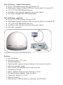
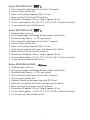
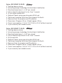
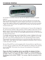
Operating instructions
For motorhomes and caravans
SAT-DOM 50 ST Digital
SAT-DOM 50 GS Digital
For maritime area
SAT-DOM 50 M-GS Digital
SAT-DOM 75 M-GS Digital
SAT-DOM 77 M-GS Digital
Innovative Mobile Technology
02/2011
language: englisch
Table of content
Generals
Introduction
Proper use and information
Safety information
Operation
Search channel configuration
Clear malfunction
Piece of equipment and mounting description
Initial Operation
Mounting example
Technical data
General functions of the receivers
Safety information
Remote control
SAT-Mouse – control without remote control
Fault code recognition
Receiver menu tree
Favorite Channel list
Editing channel list
Channel search
Extras
Video Hard Disk (HD) Recording -optional
Timer
Editing Transponder / Channels
Connections
CI Common Interface Module
DVB- T (terrestrial TV) - optional
Software updatae
Receiver DATA
Declaration of CE Conformity
Channel lists
Protection of the environment
2
3
5
9
10
11
12
13
17
18
19
20
21
23
27
28
30
32
34
37
39
40
41
42
43
46
47
48
51
Introduction
SAT-DOM M-GS
The Oyster SAT-DOM dome antenna is yet another novelty from ten Haaft which
takes fully automatic satellite reception to the next level. The actual antenna is
located under a dome, waiting for the command to find the satellite transmitting
the selected channel within just a few seconds.
Thanks to its single cable, the dome antenna is easy to mount on almost any vehicle
or boat. The space occupied by the antenna unit while it performs the necessary
adjustments does not change, as the dish pivots inside the dome. Roof hatches and
other accessories can be used without interfering with the antenna and without any
risk of damage.
All hardware components and all drive, control and sensor systems are located
inside a weatherproof dome, thus being protected against gusts of wind and airflow.
The dome antenna is elegantly shaped and very lightweight.
3
Oyster® SAT-DOM GS (for land vehicle)
Oyster® SAT-DOM M-GS (for maritime use)
The unique feature of this new system is the antenna‘s continuous tracking of the
satellite, which allows uninterrupted reception of your favourite TV or radio channel
while the vehicle is in motion. Technically, this is achieved with intelligent gyroscope stabilisation.
This system detects even the most minimal changesof the vehicle‘s direction and
immediately adjusts the elevation and azimuth angles of the antenna accordingly.
As a result, signal reception is hence maintained at all times – even in tight turns
and fast curves.
Oyster® SAT-DOM ST (only for land vehicle - static)
Unlike automatic dish antennas that must first move into position upon arrival at
the holiday destination or stop-over location, the dome antenna is fully operational
at all times. Usage only for stationary state.
Version: Oyster® SAT-DOM 50 GS / ST
z
z
42 cm unique special dish
Ø approx. 45 cm / Height approx. 38 cm
Version: Oyster® SAT-DOM 50 M-GS
z
z
42 cm unique special dish
Ø approx. 45 cm / Height approx. 38 cm
Version: Oyster® SAT-DOM 75 M-GS
z
z
47 cm unique special dish
Ø approx. 50 cm / Height approx. 48 cm
Version: Oyster® SAT-DOM 77 M-GS
z
z
53 cm oval dish
Ø approx. 66 cm / Height approx. 56 cm
4
Proper use and operation
The Oyster® SAT-DOM is developed for use on motor homes, caravans,other vehicles
or boats (Oyster® STA-DOM M-GS version). This product is designed for receiving
television and radio signals, in parked vehicles, from geostationary satellites transmitting directly to Europe.
The product (Oyster® SAT-DOM GS / M-GS) enables in addition, aiming the antenna
onto a television satellite on a moved vehicle or on a boat.
This product enables the provided antenna to be aimed manually, installed in a
stationary vehicle, onto a television satellite.
The power to the system is supplied by a standard vehicle electric system with a
rated voltage of 12 or 24 Volts. For installations where a mains connection to the
vehicle‘s electrical system is provided, a suitable 230-Volt to 12-Volt power converter must be used.
This product has been designed for use in a fixed installation on motorhomes or
camper trailers with maximum speeds of 130 km/h.
Use of the Oyster® SAT-DOM equipment for any purpose other than that specifi ed
is not permitted.
z
z
z
z
z
z
It is not permitted to change the overall device by removing or adding
individual components.
All of the relevant and approved guidelines of the automotive industry must
be observed and complied with. All instructions in the supplied Installation
Instructions must be carefully followed.
No regular maintenance is required for the product. All housings and
enclosures must not be opened.
Avoid to clean your vehicle with the mounted satellite system in a single-bay
or drive-through car wash or with a high-pressure cleaner.
The equipment must only be installed on hard vehicle roofs which are
suffi ciently strong and inherently stable.
In the event of any problems, or if you are unsure about anything, please
contact the manufacturer directly or a specialist workshop which is approved
by the manufacturer.
ten Haaft GmbH
Oberer Strietweg 8 . DE-75245 Neulingen
Tel. +49 (0) 7237 4855-0 . Fax +49 (0) 7237 4855-50
[email protected] . www.ten-haaft.com
5
Part of delivery - camper and caravan:
z Oyster® SAT-DOM antenna (Version GS oder ST)
z Powermodul (adapter between DOM and receiver) only for version GS
z 12 V / 24 V SAT-DOM Digital-Receiver
z Sat-Mouse with channel indication and remote control
z SAT-cable ; provided with TNC-special plug
Part of delivery - maritime:
z Oyster® SAT-DOM antenna (Version M-GS)
z Powermodul (adapter between DOM and receiver) only for version M-GS
z 12 V / 24 V SAT-DOM Digital-Receiver
z Sat-Mouse with channel indication and remote control
z SAT-cable ; provided
*
*PowerModul only for Oyster SAT-DOM GS / M-GS
Features:
• Easy to operate
• Elevation range: < 10° to 60°
• Unlimited pivoting
• Digital satellite search and identification at the touch of a button
• Extensive reception range
• High-quality craftsmanship and durable materials
• Aerodynamic design
• Water-repellent design prevents freezing in winter
• NO condensation problems inside the dome
• Connected voltage 12 V / 24 V
• Made in Germany
• Manufacturer is QM-certified in accordance with ISO 9001
6
Oyster SAT-DOM 50 ST
• Fully automatic adjustment in less than 15 seconds
• 42 cm unique special dish
• Space-saving mounting plate (50 x 37 cm)
• Dome resistant to hail and UV radiation
• Dimensions: Ø approx. 45 cm / Height approx. 38 cm
• Current consumption: 0.5 A at 12 V / 0.3 A at 24 V (without receiver)
• 3-year warranty and reliable service
Oyster SAT-DOM 50 GS
• Tracking dome antenna
• Internal gyroscope technology for directional stabilisation
• Directional adjustment: +/- 60° per second
• Fully automatic adjustment in less than 7 seconds
• 42 cm unique special dish
• Space-saving mounting plate (50 x 37 cm)
• Continuous reception with clear view towards the South
• Dome resistant to hail and UV radiation
• Dimensions: Ø approx. 45 cm / Height approx. 38 cm
• Current consumption: 1.2 A at 12 V / 0.6 A at 24 V (without receiver)
• 3-year warranty and reliable service
Oyster SAT-DOM 50 M-GS
• Tracking dome antenna
• Internal gyroscope technology for directional stabilisation
• Directional adjustment: +/- 60° per second
• Fully automatic adjustment in less than 7 seconds
• 42 cm unique special dish
• Optional: Space-saving mounting plate (Ø 40 cm)
• Continuous reception with clear view towards the South
• Dome resistant to seawater and UV radiation
• Dimensions: Ø approx. 45 cm / Height approx. 38 cm
• Current consumption: 1.3 A at 12 V / 0.7 A at 24 V (without receiver)
• 2-year warranty and reliable service
7
Oyster SAT-DOM 75 M-GS
• Tracking dome antenna
• Internal gyroscope technology for directional stabilisation
• Directional adjustment: +/- 60° per second
• Fully automatic adjustment in less than 7 seconds
• 47 cm unique special dish
• Optional: Space-saving mounting plate (Ø 40 cm)
• Continuous reception with clear view towards the South
• Dome resistant to seawater and UV radiation
• Dimensions: Ø approx. 50 cm / Height approx. 48 cm
• Current consumption: 1.7 A at 12 V / 0.9 A at 24 V (without receiver)
• 2-year warranty and reliable service
Oyster SAT-DOM 77 M-GS
• Tracking dome antenna
• Internal gyroscope technology for directional stabilisation
• Directional adjustment: +/- 60° per second
• Fully automatic adjustment in less than 7 seconds
• 53 cm oval dish
• Optional: Space-saving mounting plate (Ø 40 cm)
• Continuous reception with clear view towards the South
• Dome resistant to seawater and UV radiation
• Dimensions: Ø approx. 66 cm / Height approx. 56 cm
• Current consumption: 1.9 A at 12 V / 1.0 A at 24 V (without receiver)
• 2-year warranty and reliable service
Safety information
Maintenance:
The Antenna SAT-DOM is maintenance free.
The Dome must not be opened in no case
Security advice:
Proof once in a while the sturdiness of the antenna mounting. For damages caused by insufficient fixation of the antenna system, we do not take
responsibility. Please make sure, that the complete system is sealed properly, to avoid the penetration of humidity. Please do not demount or open
the dome and do not disassemble the system inside – else if any claim on
warranty expires.
Mounting / Function of the system:
For the quality of reception an appropriate place of location is needed. It is necessary, that there is between SAT-DOM and satellite no buildings, trees, bridges, masts
or other reception barrier. Obstacles would bloc the satellite signal and may cause a
bad or no reception.
Oyster® SAT-DOM GS / M-GS
Short interruptions or interference of the satellite signal, are corrected by the
reception system itself, by adjusting automatically. This means, that the connection
to the satellite is reconstituted, when the obstacle is passed.
Oyster® SAT-DOM ST
The system reconstitutes the connection to the satellite immediately after an interruption, when the signal is received again.
9
Operation
Search channel configuration:
There is no need for any programming of the Sat antenna System for other
satellites.
The SAT-DOM starts automatically, wenn the receiver is switched on. The receiver
controls the SAT DOM.
The SAT DOM is parked 10 seconds after the receiver is switched of.
The following Satellite list are preprogrammed in the DOM and Receiver:
Hispasat
Atlantic Bird 3
Amos
Thor
Astra 4
Eutelsat W3A
Eurobird 9
Hotbird
Astra 1
Astra 3
Astra 2
Hellas Sat
Türksat
30° West
5° West
4° West
1° West
5° Ost
7° Ost *
9° Ost *
13° Ost *
19,2° Ost
23,5° Ost
28,2° Ost
39° Ost
42° Ost
* Only receivable under optimal circumstances.
Reception depends of the area.
10
Clear malfunction:
symptoms
error cause
No function and no positioning noise
– Proof the power supply
- Power module connected? 11-28 V/DC or by
power supply unit 230V /AC.
- SAT receiver switched on?
- SAT connection cable linked properly?
Continuous positioning noise. No reception.
– On the first initialization, the adaptation of the
system may take a while. The system needs to
adjust to the new location
- Prevents a build-up or an other obstacle the
reception? Corrective -> change position
Antenna has positioned, no further adjusting
noise, but no reception:
- Verify the configuration of the receiver, switch
channel
- Proof the connection between TV and receiver
Sudden Interruption of the TV signal
- An obstacle in the reception line for a short
time. The Antenna finds immediately again the
satellite position again (GS / M-GS)
- Verify the power supply
Breakdown of the TV signal. Noise of motion
continuously inside the DOM
Separate the receiver and the POWER-MODUL
from the power supply. Wait a minute and reconnect the connections again.
Others
- Radar or airport near
- Mechanical damage is sometimes not visible
from outside. The dome is made out of flexible
material.
11
Piece of equipment and mounting description
Initial Operation:
Attention !!!
Switch on TV and Satellite receiver only if all cable links are connected.
Switch off the devices before disconnecting the cables. Else if, the receiver
may be damaged.
Use for the connection of the SAT dome, POWERMODUL and receiver the appropriate double shielded Satellite HF cable (Part of delivery). The motorhome and caravan
versions of the cable heads have a “F” screw connector.
The maritime versions of the HF-cable is fixed on one side with the DOM.
Receiver
OFF
ON
COMMON INTERFACE
Oyster SAT-DOM
HD
RS 232
3A
Scart or
HDMI-cable*
10A
HF-cable
PowerModul
*depends on receiver product type
PowerModul only for Oyster SAT-DOM GS / M-GS
12
TV
Piece of equipment and mounting description for
Mounting example:
mounting plate with bolt
(TNr.: 3.820.0120)
app
rox
. 50
!)
cm
. 44
cm
rox
M
37
ox.
cm
O
T-D
(SA
app
r
app
Please mount the automatically adjusting satellite reception system with the provided mounting plate on a horizontal sturdy underground.
Mounting the SAT-DOM
on motor homes
Cable out –
into direction
vehicle rear.
Cable out – into
direction vehicle rear
Driv
ing d
irect
ion
13
Piece of equipment and mounting description for
Mounting plate:
not part of the delivery
Please mount the automatically
adjusting satellite reception system on a appropriate place.
Kabelausgang
Mounting option:
Mounting plate (3.280.0122)
(not part of the delivery)
14
Piece of equipment and mounting description for
SAT-DOM 50 M-GS
SAT-DOM 75 M-GS
15
Piece of equipment and mounting description for
SAT-DOM 77 M-GS
16
Piece of equipment and mounting description
Technical data:
Antenna:
Oyster SAT-DOM
LNB F = 0,3 dB
Oscillator frequency 9,75/10,6 GHz
Receiving frequency:
10,7-11,7 GHz (lower range)
11,7-12,8 GHz (upper range)
Minimum EIRP 50 dBW
Elevation range <10°-60°
Azimuth range 0°-360° - no limitation.
Operation at environmental temperature range -20°C up to 45°C
Connection:
Cable comes out with TNC Plug
Power supply 11-28V by POWERMODUL
Current consumption: See chapter Proper use and operation
General:
Oyster SAT-DOM 50 ST / GS / M-GS
Ø approx. 45 cm / Height approx. 38 cm / Weight approx. 8 kg
Oyster SAT-DOM 75 M-GS
Ø approx. 50 cm / Height approx. 48 cm / Weight approx. 11 kg
Oyster SAT-DOM 77 M-GS
Ø approx. 66 cm / Height approx. 56 cm / Weight approx. 14 kg
Mounting:
with the provided mounting plate on a horizontal sturdy
underground. (optional for M-GS version)
POWERMODUL: processor controlled POWERMODUL
Input voltage 11-28V/ min 2 A
F-Connection for dome and receiver
At the end of its lifecycle, this product must not be disposed of with
your normal waste, but instead must be returned to a recycling facility
for electric and electronic devices. This is indicated by the symbol on
the product, the operating manual or the packaging.
17
Safety information
Place the receiver in a place with sufficient air circulation and away from
any heat sources. This will prevent heat accumulation inside the receiver
and ensures a longer lifecycle.
Do not place any items on the receiver – malfunctions, damage and even
self-ignition may occur if the ventilation openings are blocked.
To avoid the risk of fire or damage to the device the receiver must never be exposed
to moisture or rain.
Should an item or liquid get into the housing, immediately disconnect the device from the power supply and have it checked by a qualified professional before
further usage.
Should you ever notice an unusual smell or smoke, immediately disconnect the
device from the power supply and have it checked by a qualified professional.
Switch off the receiver before connecting other devices.
The power supply line to the receiver must have a cross-section of 0,75
to 1,5 mm² and must be connected directly to the vehicle battery. Ensure
that the device is not connected to an electronic charge controller.
Keep a sufficient distance to potential sources of interference such as mobile phones, electronic heater controllers, ignited components or radio devices when routing
the lines and positioning the components.
It is recommended that you ground your television set in the vehicle to
avoid interference on your television set or satellite receiver. Only connect
the freely accessible ground of your television set to the vehicle chassis.
Only use the wiring harnesses supplied or the extension wiring harnesses available
as accessories to connect the antenna unit.
Take care that there is no obstacle e. g. tree or traffic sign, which might
disturb erecting the antenna.
18
Remote control
Switches the system on or off. (Power)
TV
PAUSE
RADIO
AV
TEXT
SWAP
LIST
TV
EXIT
P+
-
Mute function of speakers.
SLEEP function - press 3 sec to activate
OK
AV
+
LIST
P-
1
Display of program list
MENU
2
3
ABC
DEF
4
5
6
GHI
JKL
MNO
7
8
9
PQRS
TUV
WXYZ
0
-
Volume down. Changing of values in menus
Volume up. Changing of values in menus
OK
PVR
INFO
RADIO
SWAP
EXIT
MENU
P+
-
Activates the loop-trough of the satellite and video signal
+
INFO
Activation of TV mode
OK
Select or confirms functions
Display of current program information (EPG)
Activation of radio mode
Return to previously selected channel
Closes on-screen menus
Display of on-screen menus
P+
Program up. upward in menus
P-
Program down. downward in menus
+
P-
0-9
Number keys for direct channel selection
Direct selection, video/audio settings
TEL: +49(0)7237/4855-0
www.ten-haaft.com
PVR
Opens the control menu of the personal Video Recorder (optional)
Starting DVB-T program search (optional)
Caro Digital MA: Starting Menu Intelligent satellite recognition system.
OYSTER Internet: Starting satellite search
19
Sat Mouse - Control without remote control
1
2
3
4
1 Satellite-mouse connector (RJ-45) 2 Left satellite-mouse key
4 Remote-control receiver
5
3 Display
5 Right satellite-mouse key
The two keys on the satellite mouse (see graphic on this page below) allow the
following basic functions of the receiver to be controlled without the remote
control:
Change to the next channel in the channel list
Change to the previous channel in the channel list
Pressing both keys briefly at the same time toggles between RADIO and TV mode.
Pressing both keys longer will cause the antenna to retract und the system to switch off.
This corresponds to pressing the red stand-by key (ON/OFF) on the remote control.
When in stand-by mode, a brief press on both keys switches the system back on.
If the receiver is in the Stand-by mode “energy saving”, it can only be restarted
by these keys both keys.
Another control element is the master switch on the front of the receiver. In position „0“ or „OFF“ the complete system is disconnected from the vehicle‘s power
supply. The switch must be in position „I“ or „ON“ for the system to operate.
Should the system no longer respond to commands, set the master switch to „0“
for approx. 10 seconds and then back to „I“ to reboot the operating software of the
receiver.
20
Fault code recognition
Malfunctions of the automatic antenna unit may occur e. g. when the antenna‘s
motion is obstructed by branches or snow. Such malfunctions are automatically
detected and will be displayed by the satellite mouse as fault codes.
E 07/
E 09
Short-circuit/open circuit in antenna cable or at antenna:
Check the white antenna cable and the connectors at the receiver and
at the LNB.
E 10
The supply voltage drops considerably:
Recharge the battery as soon as possible. Check the wiring and the
connection of the system to the voltage supply. .
E 16
Incorrect model configuration. / Error occurred during model
configuration:
An update may have been performed incorrectly. The system must be
serviced by the manufacturer.
E 17
Re-Init activated.:
Undefined memory content detected. The faults were corrected.
Switch the system off and back on. You may have to change some
settings (e. g. search satellite).
No
Display
No power supply:
Maybe the violet fuse at the receiver has a fault. Replace it by a new 3A
fuse. If the system is a 24V one, you may also use a 2A fuse.
Invert poles - power supply:
Please check the correct positioning of the electric + and - connections
and voltage. If this is left for too long, the receiver may be damaged. !!
External Sat Mouse Display not plugged:
Check if the RJ plugged in or snapped.
21
Stand-by Mode “low current”:
This is no error. Please restart the system by pressing both buttons of
the SAT Mouse.
The receiver is in failure mode:
Switch the receiver off by the main circuit breaker. Restart after 10
seconds. (Hardware reset).
Other power supply problems:
The voltage breaks down or malfunctions from the power supply.
(Perhaps charge controller or others.) Always connect the system
directly to the battery, never via charge controller or charge device).
A software update couldn’t be performed without faults:
Repeat the software update. Ask customer service for correct data.
Check the wiring.
A Hardware fault occurred:
The receiver indicated a hardware fault or hardware configuration and
has to be inspected by customer service.
22
Receiver Menu Tree
MENU
access with button “MENU” on remote controll
Audio channel
Teletext
EPG
Favourite lists
Edit Channel
Edit Transponder
Main Menu
Channel List
Edit Entries
Satellites
Transponder
Channels
Favorite lists
Sort channels
Search channels
Professional scan
Edit settings
General options
OSD / EPG / DVB SBT (subtitle)
Reception / equipment ctrl. / DiSEqC
Satellite sytems
Signal output
Factory defaults
Saving settings
Extras
System info
Signal strengtht
Sleep timer
Stream info
Erase harddisk
Calendar
Game
Game Snake
Timer
Satellite update
Encryption
Help
SAT-DOM GS/ST Receiver / Standby Mode / LED Display upside
23
Use with remote control:
P-
+
P+
-
OK
MENU
EXIT
Function
Menu Level
To configure/ to see
Audio channel
1. Menu Level
Choice of Audio- and Video channels, if provided
by the channels: language, stereo
Calender
Main Menu / extra
date
Channels
Main Menu/ channellist/
edit entries
Configurations, needed for reception of the single
channels, watch and modify
Encryption
Main Menu
display State CI Module, configuration Smartcard
EPG
1. Menu Level
show Programm info
Erase harddisk
Main Menu / extra
Optional, if receiver with hard disk
Factory defaults
Main Menu / edit settings
Back to Factory defaults
Favourite lists
Main Menu / channel list
a favourite list is a choice of channels out of the
whole provided channel list.
Generals
Main Menu / configuration
Time zone, summer time, language, search
encrypted channels
OSD/EPG
Main Menu / edit settings
Onscreen display – brightness, duration flash
Professional scan
Main Menu / channel list
Only a certain transponder is scanned
Reception
Main Menu / configuration
5V Antenna power supply, DVB-T (optional)
OSD / EPG / DVB SBT (subtitle)
Reception / equipment ctrl. / DiSEqC
SAT-DOM GS/ST
Receiver
1. Menu Level
turning SAT Mouse Display / LED Display display
configure Stand-by Mode
Satellites
Main Menu / channel list/
edit entries
Use only with competence: Orbital position of
satellite can be modified
Satellite systems
Main Menu / edit settings
Use only with competence: limination of the
active channel list
Satellite update
Main Menu
Software update via satellite
Search channels
Main Menu / channel list
Channel search of selected satellites
Signal output
Main Menu / edit settings
Configuration signal output
Signal strength
Main Menu / extra
See Signal strength
Sleeptimer
Main Menu / extra
Automatic switch off after x minutes
Sort channels
Main Menu / channel list
Choosing channels by O.K. change order
24
Function
Menu Level
To configure/ to see
Stream Info
Main Menu / extra
display state of signalprocessing
System info
Main Menu / extra
display state of Software + System
Teletext
1. Menu Level
display Teletext
Timer
Main Menu
Start of auto recording (optional HD)
Transponder
Main Menu / channel list/
edit entries
Configurations, needed for reception of the
single transponder, watch and modify
Receiver lists
Satellite list (All noted satellites)
Pre-programmed – software updateable
z
z
z
z
001 Astra 19,2 °O
002 Hotbird 13 ° O
005 Sirius 5 ° O
„ etc.“
Channel list (All receivable channels )
Channel number --> program, satellite, transponder
Pre-programmed – software updateable
z
z
z
z
0011 NDR
0012 RTL
0013 BBC
„ etc.“
Favourite lists (Personnel choice of programs out of channel list)
Remote control position ‚ Channel number, programm, Partly pre-programmed –
individually configurable
z
z
z
Remote control position 1
Remote control position 2
„ etc.“
25
Not visible in the receiver menu tree menu items
Configuration only with competence
Service Menu:
Choose the menu item SAT-DOM 50 GS/ST Receiver‚ configuration and press in the
menu item LED Display turning the die MENU-button of the remote control to enter
the service menu.
Sat - Maus Display:
The standard configuration of the SAT – Mouse display is 4 digits.
UHF Channel (TV OUT):
This item enables you to adapt the picture carrier frequency to your television set.
The range starts from C 21 (471.25 MHz) to C 69 (855.25 MHz). The standard configuration is C 32 (559.25 MHz).
This configuration does only matter if you use a „simple“ antenna cable.
Audio IF mode (TV OUT):
This item enables you to adapt the sound carrier frequency to your television set.
The possible configurations are B/G (5.5 MHz), I (6.0 MHz) or D/K (6.5 MHz). The
common configuration is B/G (5.5 MHz).
This configuration does only matter if you use a „simple“ antenna cable.
26
Favourite channels list
Your digital CI receiver provides 9 freely programmable favourite channels lists. A
favourite channels list is a selection of channels from the list of all channels.
When a favourite channels list is activated, only the channels maintained in this list
are available, all other channels will be suppressed.
The possibility of creating up to 9 different favourite channels lists allows different
system users to create personal lists without having to change the complete list of
channels.
Creating favourite channels lists:
The favourite channels lists are maintained under MENU , Main menu , Channel list
, Favourite lists. In this submenu, any channel from the complete channel list can be
allocated to any of the 9 favourite channels list. For operation, observe the help text
displayed at the bottom of the screen.
To exit the editing dialog of the favourite channels list, press EXIT two times. Changes must be confirmed with OK.
Using favourite channels lists:
Start the selection menu of the favourite channels list by pressing the „0“ key. Use
P+/P- to select a list and confirm your selection with OK. Now, the channel list only
provides the channels maintained in the selected favourite channels list. To regain
access to the full range of channels, press „0“ again and select <none>. As a shortcut, you may press „0“ „0“ on the remote to deactivate any active favourite list and
gain access to all channels in the list. Please note that you can directly select any
channel even if a favourite channels list is active.
The following Favorite lists are pre programmed:
z
z
z
z
z
1-5
6
7
8
9
free choice
Scandinavians Programs
English Programs
French Programs
Greek Programs
27
Editing sender list
You can adjust the channel list of your receiver to your personal requirements.
We suggest to group the channels by the satellites as with the default channel
list.
Select the channel list editor within the option „Sort Channels“ in the sub-menu
„Channel list“ in the main menu. After completing your settings, exit the channel
list with EXIT. Confirm the subsequent prompt with OK to save that channel list.
To change the entries, select an entry in the list by pressing OK. A menu with the
available options will appear. Select option „Block“ in this menu if you wish to edit
a complete block of sequential channels.
The menu will then disappear and you will be prompted to highlight the end of the
block in the list. Select the last entry of the block and press OK. The menu with the
available options will then be displayed again.
The following functions are available within this menu:
Copy:
Copies the channel to a different position in the channel list. The existing entry in
the target position is overwritten.
Move:
Moves the entry to a different position. Note: Moving an entry upward will insert it
ahead of the target entry, moving it downward will insert it behind the target entry.
Delete:
Deletes a channel from the channel list. The entry in the list will be marked as unused. The numbering of the remaining channels will remain unchanged.
Cut:
Deletes a channel from the channel list. The subsequent entries are moved up to
fill the free position. Note: To help keep the channels grouped in blocks, all of the
channels move up together only as far as the next entry marked as „unused“. If e.
g. the list is not occupied between entry 85 and entry 99, you may delete entry 57,
and only channels 57 to 84 will move up. The channels from 100 are not affected.
28
Insert blank:
Inserts a blank entry. The subsequent channels are moved downward accordingly.
Note: As with the option „Cut“, this function determines areas with channels
marked as „unused“ as the end of a block.
Pack:
This option is only available if you have highlighted a block. Within this block, all
free positions marked „unused“ are deleted by moving the channels upward. The
unused entries are then positioned in sequence at the end of the block. Functions
utilizing a target entry will prompt you to select a target entry after the selection
of the corresponding menu option. To do this, navigate to the entry in the list and
confirm with OK.
You can cancel the preceding steps by pressing EXIT as long as you have not completed a function. As an alternative to the direct editing of the channel list, a cache
memory is available for the convenient execution of complex sorting procedures.
Further operating information concerning the individual functions will be displayed
on screen.
29
Channel search
The automatic search function of the receiver scans the individual satellites or,
alternatively, the DVB-T channels for new channels.
Channels already included in the channel list are automatically updated in case of
any changes. Depending on the settings in „Edit Settings , General Options“, encrypted channels may be ignored
When the mobile search is started, all DVB-T channels are first deleted from the
channel list (yellow button).
Starting the channel search:
To start the channel search, select MENU, Main menu, channel list, then option
channel search.
Select a satellite (or DVB-T) from the list that you wish to search for new channels
and confirm your selection with OK. Note that the antenna must be aimed at this
satellite and that a signal must be received. To receive DVB-T signals, a suitable
antenna must be connected.
Wait until the search has been completed. During the channel search, technical
details of the scanned channels and the number of channels found are displayed. A
search may well take approx. 15 minutes. After the search is completed, the channel-selection window will be displayed.
Channel-selection window:
This window shows the channel list on the left-hand side and the new channels
on the right-hand side. To switch between TV or RADIO channels, press the TV and
radio buttons.
The new channels (list on right hand) can be transferred into the channel list, using
the following menu option
Therefore please choose a channel and press the O.K. button.
z
z
Activate:
Copy above:
Activates the new channel, if possible.
Inserts the selected new channel above an existing channel
list entry. This entry and the subsequent ones will be moved
down the list to make space for the new entry.
30
z
Copy over:
Copies the selected new channel over an entry in the channel
list. The existing entry is overwritten.
Use the SWAP key to toggle between the channel list on the right and the channel
selection. If you have navigated to the left-hand channel list using the SWAP key,
the following options can be applied to the newly found channels:
z
Activate:
Restore:
z
Cut:
z
Delete:
z
Activates the selected channel.
This option prevents previously scanned channels from being
updated. Previously scanned channels are marked green in the
channel list.
Deletes a channel from the channel list. The subsequent
channels are moved up to fill the free position.
Deletes a channel from the channel list. The entry in the list
will be marked as unused. The numbering of the remaining
channels will remain unchanged.
SAVING the channel list:
After inserting the new channels into the channel list according to your personal
preferences, press EXIT. A dialog box will appear and you will be prompted to either
save your changes with OK, cancel your changes with SWAP or to return to the
channel selection window with EXIT.
If you decide to cancel your changes (SWAP), the original channel list will not be
changed and all the changes will be lost.
Further information on the search function:
Make yourself familiar with the search function and use it regularly. Digital
television is a comparatively new technology, and new channels are added
frequently.
Also, the data of existing channels is subject to change.
The search function automatically updates the internal channel list when you confirm the security prompt with „OK“ when leaving the search function, even if you
have not made any manual changes.
31
Extras
1. Signal-strength display
Within the sub-menu „Extras“ in the main menu you can select the signal
strength display.
The signal strength is then indicated as a vertical bar. The C/N value will indicate
the same value in dB. The higher the number, the better the reception quality. In
satellite mode, and depending on the channel, a satisfactory TV picture should be
received with any value above approx. 8. In DVB-T (optional) mode, a C/N value
above approx. 15 will provide interference-free reception.
The three coloured fields next to the bar indicate the status of the receiver stages.
Only if all fields are green, will valid data be received with the signal and a picture
be shown on screen. Use P+/P- to change the selected program in the background.
Press INFO to display an enlarged version of the C/N-value window.
Pressing the INFO button on your remote control enlarges the display of the signal
strength.
Note:
Further to the setting of your reception system and your position within the
satellite‘s footprint, the signal strength also depends on the currently selected
channel. Please take this into account when checking the aim of your antenna using
the signal strength display. It is normal that some channels are received with a
strong signal while others are rather weak.
32
2. System Info:
In the menu tree „Extras/System Info“ you find details about the Software
Version and Serial Numbers of your receivers.
This information is needed for service purposes or Software updates.
Example:
z
z
z
z
ten Haaft Serial: 2800805030
ten Haaft Build: EU/2.11
uC-Firmware: 5.010
Motor Revision: 00403 (only in full automatic antenna system)
3. Sleep-timer:
The sleep-timer automatically switches off the system at a preset time. To activate
the sleep-timer, select MENU , Main menu , Extras , Sleep-Timer. In the configuration settings of the satellite system, you can select whether the system shall retract
completely when the sleep timer is active or whether it shall switch into the sleep
mode with the antenna open. The sleep-timer works completely independently of
the regular timer.
Please note:
When your receiver is switched off by the sleep-timer, the TV set may remain on
and hence consume power. Some TV sets switch off automatically if no video signal
is received or are remote-controlled via the SCART cable. The digital CI receiver
provides the corresponding control signals at its SCART port. Please refer to the
operating manual of your TV set to determine the options The Sleep timer.
33
Video Hard Disk (HD) Recording - optional
Recording and playback of programs via the integrated hard disk is performed in
PVR mode (PVR – Personal Video Recorder).
To switch into PVR mode, press the PVR key. To return to normal receiver mode,
press EXIT.
In PVR mode, a graphic is displayed in the upper left corner of the screen which
shows symbols of all functions currently available. These can be selected via the
number keys shown in the graphic.
Use the OK key to toggle between the different views of the PVR mode. Use the +/–
key to change the volume when in PVR mode.
Recording:
Key
Symbol
Description
0
Starts the recording.
5
Starts the recording and stops the running video.
0
Stops the running recording.
Playback:
Key
Symbol
Description
7
Displays the recordings overview. This overview shows all recorded programs
for playback or deletion.
2
Starts the playback at the beginning of the currently running recording or
changes from fast forward or rewind or pause back to normal playback.
1,3
Fast Forward/Rewind. Accelerates the playback of the recording. By pressing
key 1 or 3 multiple times, up to six speeds can be selected in either direction.
4,6
Moves 5 minutes forward or backward within the recorded program.
5
Interrupts playback.
9
Stops the playback of a recorded program and returns to the playback of the
live program.
8
Stops playback and opens a menu with cutting functions.
LIST
Opens a list with index marks which can be either selected or directly activated by pressing OK.
34
The receiver can record and playback simultaneously and independently. Only the
currently selected channel can be recorded. At the same time, either a previously
recorded program or time-shifted, the current recording can be played back.
The status of the recording or playback is indicated by one or two status bars at
the bottom of the screen. If neither recording nor playback is active, the status bar
indicates „LIVE“. During recording the status will indicate „REC“ and the elapsed
recording time. During playback the status bar will indicate „PLAY“, „FF“(Fast
Forward), „FR“ (Fast Rewind) or „PAUSE“. This status bar shows the current position
within the recorded program in time format and by a progress bar. To the right of
the progress bar, the total time of the recording is indicated unless the system plays
back the running recording in time-shifted mode. The elapsed recording time of the
running recording is shown in the „REC“ line.
Multi-channel operation
During the recording of a program, other channels transmitted on the same transponder can be directly played back without interrupting the running recording.
To view such channels while a program is being recorded, exit the PVR menu by
pressing EXIT (the recording is continued in the background) and then press LIST. A
channel list is displayed containing all channels available for selection. One restriction may apply: When playing back or recording encrypted channels, the decoder
module may not be able to decode two programs at the same time. To stop the
recording in the background, reactivate the PVR menu by pressing the PVR key.
35
PC connection (USB 2.0):
If the PVR menu is shown on screen but neither the playback nor the recording
function is active, the hard disk can be controlled by a personal computer connected to the „HD“ port (USB 2.0) by pressing key „8“. This function must be confirmed
by pressing OK. The computer will maintain control over the hard disk until the PVR
key is pressed again. Press OK to confirm that the control of the hard disk is passed
back to the receiver.
When the hard disk is controlled by a computer via the USB 2.0 port, programs
stored on the hard disk can be downloaded if suitable software is installed.
The following software (examples) is suitable to download and edit recorded programs:
DVR-Studio PRO (www.haenlein-software.de)
DigeniusDiskX (www.sourceforge.net/projects/digeniusdisk)
Erasing the harddisk:
To erase all records on the hard disk, please choose main menu / extra / erase hard
disc. This erases all records. To erase certain single records, you got to switch by PVR
MENU into record overview and select there the record you like to erase. There is no
back up for erased records.
36
Timer
The timer is determined to process comfortably a hard disc record by time
control.
Timer recording – receivers without „HD“ option:
The timer is used to conveniently record programs on the hard disk at preset times.
The timer function is also available on devices without optional hard disk. This
function is particularly helpful if you want to be sure not to miss a program on a
certain channel. The receiver will then switch over to the channel as programmed in
the timer.
The timer can manage up to 12 recording sessions. Either a defined recording date
or individual days of the week can be selected.
To program sessions, select „Timer“ from the main menu. The overview shows all
dates of the 12 entries. Use the OK key to edit individual entries. To determine whether a fixed date or fixed weekdays are programmed in the timer, press the LIST key
when in the date line. If a time before the starting time or identical to the starting
time is set as end time, the recording will continue into the following day.
The correct function of the timer requires the internal clock to be set correctly.
Check the time displayed in the status bar to verify.
To exit the timer settings, press EXIT at any time. If any setting has been changed or
added, press OK to confirm the storing of the changes.
Programming programs from the EPG:
Programs from the EPG can be directly copied into a free timer position by pressing
LIST in the overview of the day or in the details window of the EPG. The timer menu
then appears so that the new entry can be edited manually. Press EXIT twice to exit
the settings dialog.
37
Timer and Stand-by:
The timer is only active when the system is switched on or has been set to sleep
mode with the antenna open. The timer is inactive in stand-by mode. The antenna
does never open automatically and without direct user control.
In sleep mode, the system checks whether there are timer programs that have to be
processed. In this case, the sat mouse will show four vertical bars (||||), indicating
that the system is in timer stand-by and is hence being controlled by the timer
which will reactivate the system at the preset time. The power consumption in
timer stand-by is higher than in regular stand-by.
38
Editing transponders / channels
Configuration only with competence
The program menu (press MENU once) contains the two sub-menus „Edit
Transponder“ and „Edit Channel“. These two sub-menus allow you to view and
edit the settings required for the reception of the individual channels. Wrong
entries at the individual positions may prevent the reception of one or more
channels.
The program menu (press MENU once) contains the two sub-menus „Edit Transponder“ and „Edit Channel“. These two sub-menus allow you to view and edit the
settings required for the reception of the individual channels. Wrong entries at the
individual positions may prevent the reception of one or more channels.
The automatic search function usually provides the correct settings automatically.
Under certain conditions, you may input settings received e.g. from your broadcasting station to enable the reception of specific programs.
When the decoding function of the digital CI receiver is used, encrypted programs
can only be decoded if the correct data is entered in the menu „Edit Transponder“
under „Network ID“ and „T.Stream ID“. These settings must be checked and adjusted,
if required, when the satellite‘s channel allocation is changed by the operators.
If an encrypted channel for which you have a valid smartcard cannot be decoded,
select „Edit Transponder“ and highlight „Network ID“. Press LIST. Changed settings
are now automatically corrected. In this case, the entry will change to green. Press
EXIT and confirm the confirmation prompt with OK. Your channel list is now up to
date and the encrypted program can be received.
39
Connections
A
B
OFF
C
D
COMMON INTERFACE
HD
ON
RS 232
3A
A
B
C
D
10A
Master switch ON/OFF
RS-232 port for software updates
Slot for CI module
PC interface, harddisk (optional)
12 13
14 15 16 17
18 19
20 21
22
DVD IN
SAT
DVB-T
ANTENNA
CONTROL
Y/G
CVBS
U/B
V/R
IN
SAT
MOUSE
IN
TV
OUT
12 – 24 V
OUT
OUT
R
Y/C
L
SPDIF
AUDIO
11 10
9
8
7
6
TV OUT
EXT IR
5
4
1
2
3
4
5
6
7
8
9
3
2
1
Power supply (- brown = ground; + red = 12 - 24 V; black = free)
Unused
Auxiliary external infrared receiver (optional)
For satellite mouse connector (channel display and remote-control receiver)
Digital audio out, switchable in menu, e.g. for 5.1 sound systems
Audio out left, also for external speakers, HiFi system etc.
Audio out right, also for external speakers, HiFi system etc.
Brightness and colour components (S-VHS -signal or Y/C-signal)
Analogue high-frequency signal
10 LOOP for sat signal, e.g. for auxiliary receiver
11 LOOP for DVB-T signal, for auxiliary DVB-T receiver or decoder (optional)
12 Connection for antenna cable from optional or external DVB-T antenna (optional)
13 F-jack for satellite cable (coaxial cable of satellite system)
14 CVBS-video signal: for colour, brightness, sync
15 Y-signal / G-signal (for many LCD devices)
16 U-signal / B-signal (for many LCD devices)
RGB-signals / YUV-signals
17 V-signal / R-signal (for many LCD devices)
18 Audio-DVD in right
19 Audio-DVD in left
20 CVBS-Video-DVD in
21 SCART socket
22 Unused
}
40
CI Common Interface
At the front of the device there are two slots for modules to decode encrypted
programs.
To prevent damage only modules with the „PC Card“ logo must be inserted. Any
other modules may damage the receiver beyond repair. Do not use excessive force
to insert the modules. Rather pull the module back out of the slot and try inserting
it again. Ensure that you insert the module with the correct side up and correctly
inserted into the slot.
Smartcards are sometimes printed in a confusing way as they are often designed to
be used with other decoders. Most common-interface modules allow cards with the
golden contacts facing upward. Before inserting a smartcard into the common-interface module, make sure that the usually gold-coloured contacts on the smartcard
are clean and free of dust.
If a decoder module has been correctly identified, its name is displayed in the main
menu under „Encryption“. When you select the entry for this module in the list and
press OK, a menu will be displayed based on the corresponding decoder module.
Please contact the module manufacturer in case of any questions concerning the
module. Note: Some modules only register completely and provide a menu system if
a valid smartcard is inserted.
The keys OK and EXIT are used to navigate within the manufacturer-specific menus.
If a menu does not respond to the OK or EXIT command, the dialog can be cancelled
by pressing MENU. The receiver then interrupts the connection to the module‘s
menu system.
Please note: Not all encryption systems are available to common-interface
modules yet. Please check with your pay-TV provider, if a matching module is
available. If there is no response on “OK” or “EXIT”, you can force to terminate
the dialogue, by the button “MENU”. The receiver stops the connection to the
module.
41
DVB-T (terrestrial TV) optional
In large areas of Europe, terrestrial analogue TV has been replaced by a digital technology called DVB-T. Just like satellite TV, the reception of DVB-T also requires a
receiver (also called „set-top box“). As an option, your digital CI receiver is equipped
with this additional receiver and can hence include DVB-T channels in the channel
list for playback. This requires a separate DVB-T antenna to be connected to the
corresponding antenna port.
We recommend the usage of a so-called active antenna with integrated amplifier
for extended range. The power supply required by the active antenna is provided by
the digital CI receiver. To activate the power supply, follow the path Menu , Main
menu , Edit Settings , Reception and set the option „5-V antenna supply“ to „On“.
Remember to save the changed setting.
Different frequencies are used for terrestrial TV in the different regions. It is hence
required to search for DVB-T channels whenever the location is changed (even
within one country). Each region has its own TV stations. A channel list including all
channels of all regions would hence be excessive. Therefore, it is useful to include only the channels in the channel list that can actually be received at a given
location. To facilitate this, your digital CI receiver is equipped with a special mobile
search for DVB-T channels. To start this search, press the yellow key.
Upon confirming the search with OK, all previous and not applicable DVB-T channels will be deleted and a new DVB-T search is started.
42
Software update
Via Satellite or via Internet by using the RS 232 Interface
The installation of software update is for ten Haaft DIGITAL product series systems
since September 2008. The update satellite is at the moment ASTRA1H an 19,2°
East. Updates are possible within the footprint of this satellite.
Please consider that this software update is not available for products of the VISION
series or older DIGITAL products.
Systems produced since January 2007 can be reconditioned with this feature. Therefore a singular update with a computer is necessary. For further information about
receiver updates, please visit our homepage:
http://www.ten-haaft.de/d/receiverupdate.html
Operation:
For starting an update please adjust the antenna an ASTRA1 and press on the
remote control the button MENU. Choose in the MAIN MENU the feature “Satellite
UPDATE”.
The following items are available to select with the remote control.
1. Check for updates (check available updates)
2. Display box serial number (Hardware number)
9. Boot firmware (Restart Receiver)
1. Check for updates
This menu item checks, if a update can be sent to your receiver device via satellite.
Therefore it us necessary to enter an UPDATE- CODE. This entering avoids an update
with an not appropriate or wrong software.
The correct Code you got to enter is:
1268 05 2004 22000
After entering this code a software download can last up to 10 minutes. Then a
list is displayed, where you can choose by numeric keys on the remote control the
update you like. “Firmware” is the operation system. If this is offered, your system
is in any way appropriated for a software update. “Channel LIST” is the channel list
of yours receiver.
43
Once the update has finished (notice: “UPDATE finished”) the screen stops with this
success message.
By Pressing “EXIT and “9” the receiver is restarted and the new firmware and channel list are ready for use.
2. Display box serial number:
This menu item shows the hardware serial number. This is important in case you
have to contact the customer service.
9. Boot Firmware:
With this menu item 9, the receiver an be rebooted. So the receiver can be restarted
after a successful update, at any time.
44
Software update - RS232 interface
The serial RS232 interface is used to connect the receiver to a computer. On our
website at www.ten-haaft.com you will find programs to support this functionality.
You can download updates of the operating software and up-to-date channel lists
that may resolve technical problems or provide new functions or channels.
Never use any other software updates than those provided on our website at www.
ten-haaft.com The usage of any third-party software update or software not released for your system variant may cause damage to your satellite system and may
render your warranty invalid.
If you do not have access to firmware or channel list updates, please contact your
local service center or the ten Haaft® service department (see back of manual).
The connection of the receiver to a PC requires a serial cable with a 1:1 pin allocation, i. e. hard-wired pins. The PC-side of the cable must have a 9 or 25-pin D-SUB
connector, depending on the serial port of your PC. The receiver-side of the cable
requires a 9-pin D-SUB connector. Extension cables for mice are configured accordingly and can hence be used.
The pins of the receiver port are assigned as follows:
1, 4, 6 - 9
not assigned
2
TXD
3
RXD
5
GND
45
Receiver data
Front end (IF unit)
Input frequency range
950....2150 MHz
Input level range
-65....-25 dBm at 75 Ohm
Input socket
F standard, female
Output (loop-through) socket
F standard, female (optional)
Signal decoder
Supported symbol rates
> 15000 MSym/sec
FEC
Viterbi, all current rates
Signal format
MCPC-DVB-S MPEG2 TS
CI decoding standard
by CAM plug-in modules
Audio/Video part
Video output signal
FBAS, Y/C, RGB or YUV
Audio output signal
Stereo via SCART or Cinch
Audio output level
adjustable or fixed at 0 dB
Digital audio
SPDIF Cinch (PCM, AC3, dts)
Outputs
Audio / Video
Euro SCART, Cinch, Hosiden
HF modulator
DIN / IEC channel 32 (UHF)
Other data
Operating voltage
12 V or 24 V (11 V to 30 V) DC
Power consumption of „CI“
approx. 11 W (incl. 1 CI module)
Power consumption of „CI+T“
approx. 12 W (incl. 1 CI module)
Power cons. of „HDCI+T“
approx. 15 W (during HD rec.)
Weight (incl. Antenna unit)
1,5 – 2 kg (dep. on model)
Dimensions (WxHxD, in mm)
approx. 275 x 75 x 160
Subject to change without notice
46
Declaration of Confirmity
Konformitätserklärung
Declaration of Confirmity
Déclaration de Conformité
Wir, der Hersteller, ten Haaft GmbH , Oberer Strietweg 8, D-75245 Neulingen,
GERMANY / ALLEMAGNE erklären hiermit, dass folgende Produkte den wesentlichen
Anforderungen der folgenden Vorschriften entsprechen und somit ein CE-Zeichen
in Übereinstimmung mit der EMV-Richtlinie 89/336/EWG und der KFZ-Richtlinie
72/245/EWG (i.d.F. 2006/28/EG) tragen.
z
z
z
z
z
z
z
Oyster® Digital 85 HDCI + T SKEW
Oyster® Digital 65 HDCI + T SKEW
CARO® Digital HDCI+T
CARO® Digital MA HDCI+T
Cosmo® Digital HDCI+T
Oyster® SAT-DOM ST Receiver HDCI+T
Oyster® SAT-DOM GS / M-GS Receiver HDCI+T
Eine Bescheinigung gemäß Anhang IIIC der EG-RL 72/245/EWG (2006/28/EG) liegt
dem Hersteller vor.
z
z
EN 55013 (2001) + A1
EN 55020 (2001) + A1, A2
Neulingen, den 01.11.2009
Roman Bittigkoffer
Geschäftsführer
47
Channel list
Appendix: Channel list (TV stations):
In the original channel list (TV), the programs are allocated to the individual satellites as follows:
Satellite
Position
Channel CH
Astra 1
19,2°O
001 – 499
Hotbird
13°O
500 – 999
Astra 2
28,2°O
1000 – 1269
Eutelsat W2
16°O
1270 – 1439
Atlantic Bird 3
5°W
1440 – 1499
Astra 3
23,5°O
1500 – 1599
Thor / Intelsat 10-02
1°W
1600 – 1839
Sirius
5°O
1840 – 1969
Hispasat
30°O
1970 – 2249
Astra 1 (iberian prog.)
19,2°O
2250 – 2379
Eutelsat W3A
7°O
2380 – 2399
Hellas Sat 2
39°O
2400 – 2489
Eurobird 9
9°O
2500 – 2599
Amos
4°W
2600 – 2659
Eutelsat W1
10°O
2660 – 2699
Telstar 12
15°W
2700 – 2749
Türksat 2A / 3A
42°O
2750 – 2899
BADR 3 / 4
26°O
2900 – 2949
Atlantic Bird 2
8°W
2950 – 2999
Hotbird (greek. prog.)
13°O
3000 – 3079
Hotbird (arabic Prog.)
13°O
3080 – 3299
Eutelsat W4
36°O
3300 – 3329
Astra 1
19°O
3450 – 3500
Astra 1
19°O
3450 – 3500
Channel list is subject to change without notice
48
Please note that not all program numbers are occupied by a station. Many numbers
are kept blank for further system extensions. Stations frequently stop the transmission of individual programs.
You can sort the channel list to your personal taste and you can update the list with
new channels with the search function at any time. The system function will not be
affected.
Appendix: Encrypted programs (CI):
The following encrypted programs are pre-set in the factory:
ORF (Austria) encrypted
CH 100 bis CH 111 (Astra 1)
SKY Germany encrypted
CH 120 bis CH 168 (Astra 1)
Canal + (Netherlands)
CH 200 bis CH 226 (Astra 1)
TV Vlaanderen (Belgium)
CH 228 bis CH 243 (Astra 1)
Canal Sat France (France)
CH 300 bis CH 473 (Astra 1)
SRG (Switzerland)
CH 540 bis CH 546 (Hotbird)
BIS TV (France)
CH 550 bis CH 594 (Hotbird)
Encrypted and unencrypted channels from various European countries with different
dedicated themes (fashion, music, sports, …) are located between CH 235 and CH
499. Further program packages and channels can be searched at any time using the
search function and can be stored at program positions of your choice.
Please note that the reception of encrypted programs requires the corresponding
CI module and a valid access card supplied by the program provider. Please contact
the relevant program provider for more information. The program providers will also
provide details about the type and source of the CI modules required.
Always contact the program provider directly if you require any information about
encrypted program packages or if you have technical queries.
For licensing reasons, many program packages may only be received in their country
of origin. Accurate information can therefore only be obtained from the program
providers.
49
Appendix: Choice of TV-Channels:
A part selection of the preprogrammed channels by the manufacturer on the
receiver:
1000
Sky News
1130
World Movies
1159
PopGirl +1
1001
BBC 1 London
1131
Zone Horror
1160
Tiny Pop
1002
BBC 2 England
1132
Zone Horror+1
1003
ITV1 London
1133
BBC News
1004
Channel 4
1134
BBC Parlament
1005
FIVE
1135
Bloomberg
1007
CBeebies
1136
CNN
1008
ITV2
1137
Euronews
1009
ITV2+1
1138
France 24
1010
ITV3
1139
Russia Today
1011
ITV3+1
1140
Sky News
1012
ITV4
1141
TBN Europe
1013
ITV4+1
1142
B4U Music
1014
Channel 4+1
1143
Chart Show TV
1015
E4
1144
Clubland TV
1016
E4+1
1145
Flaunt
1017
More4
1146
Flava
1018
More4 +1
1147
Rockworld TV
1019
Film4
1148
Scuzz
1020
Film4 +1
1149
Starz TV
1021
Film24
1150
The Vault
1022
Movies4men
1151
Zing
1123
Mov4men +1
1152
oMusic TV
1124
Movies4men 2
1153
Bliss
1125
Mov4men2 +1
1154
CBBC Channel
1126
Movies24
1155
CITV
1127
Movies24+
1156
Kix!
1128
True Movies
1157
POP
1129
True Movies 2
1158
PopGirl
Channel list is subject to change without notice
50
Protection of the environment
At the end of its lifecycle, this product must not be disposed of with
your normal waste, but instead must be returned to a recycling facility
for electric and electronic devices. This is indicated by the symbol on
the product, the operating manual or the packaging.
The materials can be reused in accordance with their identification. By reusing or
recycling old equipment or making use of it in other ways you are making an important contribution to protecting our environment. Please contact your local council
to find out where your nearest disposal facility is.
EC End-of-Life Vehicle Directive
The receiver is certified and intended for use as an accessory of a motor vehicle.
The system may be disposed of together with the vehicle in accordance with the
EC End-of-Life Vehicle Directive ELV, 2000/53/EC. The system does not contain any
materials rated as hazardous to the environment according to the directive.
We hope you get a lot of enjoyment out of your new satellite system!
51
ten Haaft GmbH
Oberer Strietweg 8
75245 Neulingen-Göbrichen
GERMANY
Telefon + 49 (0) 72 37 / 48 55– 0
Telefax + 49 (0) 72 37 / 48 55– 50
E-Mail: [email protected]
Office hours:
Monday – Friday 08:00 – 12:00 Hrs CET
13:00 – 16:30 Hrs CET
www.ten-haaft.com