1
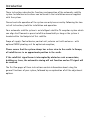
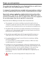
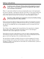
Operating instructions
Art-Nr.: 3.150.0110
+
Vision III
Vision III
DX
Vision III
Innovative Mobile Technology
Version: 03/2015 Language: English
Table of contents
General information
Introduction3
Proper use and operation4
Safety instructions
5
Controls
The first steps7
Switching ON / switching OFF
8
Menu operation9
Operating the system
Menu tree10
Automatic search11
SAT mode12
Entering the position12
Manual search12
Main menu – Settings14
Restarting the system14
General settings
Receiver control15
Language16
Dimmer16
Service INFO16
AUX relay – switched terminal for TV set
17
Satellite settings
Search satellite18
DiSEqC programming18
Appendix
What is DiSEqC?21
Notes on protection of the environment 22
Contact and Service22
2
Introduction
These instructions describe the functions and operation of the automatic satellite
system. Installation instructions can be found in the installation manual supplied
with the system.
Correct and safe operation of the system can only be ensured by following the two
sets of instructions, both for installation and operation.
Your automatic satellite system is an intelligent satellite-TV reception system which
can align itself towards a preset satellite automatically as long as the system is
located within the footprint of this satellite.
Scope of supply: Control device; control unit; exterior unit with antenna - with
optional SKEW pivoting unit for optimised reception;
Please ensure that the system always has a clear view to the south. In Europe,
all satellites are in an approximate position in the south.
If the satellite‘s signal beam is interrupted by obstacles such as mountains,
buildings or trees, the automatic aiming will not function and no TV signal will
be received.
The first few pages of these instructions contain information about using the
general functions of your system, followed by an explanation of all the adjustment
options.
3
Proper use and operation
This product has been designed for use in a fixed installation on mobile homes
or camper trailers with maximum speeds of 130 km/h.
It is designed to automatically aim a parabolic antenna mounted on a stationary vehicle at geostationary television satellites transmitting directly to Europe.
Power to the system is supplied by a standard vehicle electric system with a
rated voltage of 12/24 Volt DC. Switching-mode power supplies must not be
used for the installation of the system in camper trailers. Use of the equipment
for any other purpose than the one specified is not permitted.
Please also note the following instructions from the manufacturer:
l
The equipment must only be installed on hard vehicle roofs which are
sufficiently strong and inherently stable. All of the relevant and approved
guidelines of the automotive industry must be observed and complied with.
l
The product does not require any regular maintenance. The housings and
enclosures must not be opened. Inspection and maintenance may only be
performed by a qualified professional.
l Do not clean your mobile home with the mounted satellite system in a
single-bay or drive-through car wash or with a high-pressure cleaner.
l
It is not permitted to change the overall device by removing or adding
individual components.
It is not permitted to use other parabolic antennas or LNBs than those
installed originally at the equipment.
l
Installation must only be performed by sufficiently qualified personnel. All
instructions in the supplied Installation Instructions, which form part of the
Operating Instructions, must be carefully followed. In the event of any
problems, or if you are unsure about anything, please contact the
manufacturer directly or a specialist workshop which is approved by the
manufacturer.
l
Retract the system during periods of strong wind or storm.
4
Safety instructions
In order to ensure that your Vision system works properly, you must
ensure that it is correctly connected to the ignition of your vehicle
(see Installation Instructions).
When it is correctly installed, the antenna automatically returns to the park position when the ignition is switched on and locks itself there. If the system cannot fully
retract or cannot retract at all due to a fault, then it is your responsibility as the
driver of the vehicle to check that the antenna is safely and properly stowed.
The driver of the vehicle must inspect the external unit before driving
off to ensure that it is fully retracted.
Please note also that different legal requirements apply to the operation of electrical and electronic equipment in different countries. As the user of this equipment,
you yourself are responsible for ensuring compliance with the relevant laws and
regulations.
Your Vision system is approved by the manufacturer for connection to standard
commercially available rechargeable lead batteries with a rated voltage of
12V/24V DC and a rated capacity of at least 50Ah.
Connection to any other type of battery system can lead to irreparable damage
to the battery system or the Vision system or to the release of flammable or toxic
gases or to the self-ignition of the unsuitable battery system.
The manufacturer accepts no liability for direct or indirect damage or for consequential damage to the system itself, to battery systems, motor vehicles or other
equipment or goods resulting from the connection of unsuitable battery systems or
installation/wiring errors.
5
Safety instructions
Note on Safety - Oyster Vision III
Stop function via the control device and the remove of the power supply during maintenance.
Press the Selection button
on the keypad on the control device to stop the movement of the antenna. In this stop mode no receiver DiSEqC control commands are
executed more.
To abolished the stop function scroll via
Search“ and pressing the Selection button
, which causes that enters the antenna.
on the keypad to select „Auto
. Or by press the the On / Off button
During maintenance on the antenna system it is essential, that the operating voltage of the complete system, receiver and VISION III control box, are off.
If the system is reconnected to power, the display of the control panel „activate“.
Only after pressing the On / Off button
on the control panel, the antenna can
extend again. Please note that commercial receivers depending on the type can take
up to 90 seconds to initialize.
6
The first steps
All controls are handled via the control device.
Vision
On / Off
All controls are handled via the control device.
You may choose any location you like to install the control device, but please bear
in mind that it is not waterproof. You may still need to remove the protective film
from the display.
The display of the control device will show the various current operating modes of
the system. We recommend that the control device is positioned in an accessible
location where it is easy to see this information.
The display is illuminated, so it is not a problem if it is installed in a very dark location.
To ensure safe and reliable operation of the system, please make sure the external unit
is in rest mode before disconnecting the control device. Check that no text is displayed on the control device – this is an indication that the system is in rest mode.
We have produced a separate manual – the „Installation Instructions“ – which
covers the installation, wiring and initial taking into operation of your Vision
system.
In its supplied state, a search satellite for the automatic search is already configured in your Vision system‘s control unit.
A satellite swap is performed by changing the search satellite or via the DiSEqC
signals of the receiver. The signal or DiSEqC ID of the receiver must comply with
the ID list saved in the control unit of your Vision system.
See section: Satellite settings / DiSEqC ID.
7
Switching ON / switching OFF
Vision
On / Off System starts search from last position
There are two ways of switching the Vision III antenna system on and off:
The system can always be switched on and off via the button
on the control
device or by switching the receiver on and off. If you want the system to respond
when switching the receiver on or off, then menu item „Receiver control“ must
be enabled. See section „Receiver control“.
After switching on the system, the antenna unfolds and returns to the last position
in which a satellite was received.
If the vehicle position has changed since, the system will not receive any signals
and the automatic search is started.*
To switch the system off, press button
again to retract the system and send it
into rest mode.
If you would like to stop the movement of the antenna while it is opening or closing, simply press
to instantly stop the antenna.
Notes
Please remember to switch on your TV receiver and your TV set or flat-screen
display.
If the message „Manual search“ is displayed after the antenna has opened, and
if the system does not commence the search automatically, then the system
was being operated in manual mode when it was last switched off.
Please refer to sections „Automatic search“ and „Manual search“.
8
Menu operation
Vision
On / Off
The arrow keys
and
Selection button
Scroll
are used to navigate through all levels of the menu.
Using these keys, select a submenu, function or setting.
Press
to enable the displayed menu item. Within the settings, you can change
the displayed values within the set limits by pressing the arrow keys
and
.
Then press
to accept the set value and return to the higher-level menu.
Use button
to return to the selection level without saving the data.
By selecting menu option „Return“ and by pressing
in the menu layout.
9
you can go back up one level
Menu tree
The functions of the keys are explained in section „Menu operation“.
Menu item display
Function
Automatic search
Press
to start the automatic search for the satellite specified in menu option „Search satellite“
Swap satellite
Press
to select one of four differnet satellites
SAT mode
Press
to display the search satellite of the automatic search
Selection of position
Manual search
Selection of a position from a list; speeds up the finding of the search satellite
Manual control of the antenna dish Signal optimisation
Main menu
Press
General settings
to access the settings levels
Press
to access the submenu options of the General settings
Language
Language menu
Dimmer
Display lighting
Receiver control
Service INFO
Receiver-controlled antenna start: „Auto off“; „Standby“; „Sleep“
Serial number, antenna type, revision no. and error state
Back
Satellite settings
Press
to return to main menu
Press
to access the submenu options of the „Satellite settings“ level
Search satellite
Specification of the search satellite for the automatic search
ein/aus*
DiSEqC on/off
View DiSEqC function on/off. Satellite change via receiver
DiSEqC on < > *
DiSEqC V3-ID *
DiSEqC function on / off
Viewing or assigning a VisionIII DiSEqC ID to a specific satellite,
e.g. ASTRA 1 *
Select satellite
DiSEqC V3: <001> *
DiSEqC Rec-ID *
Receiving the receiver DiSEqC ID
DiSEqC Rec: 001 *
DiSEqC Data *
Display of receiver DiSEqC ID
DiSEqC transfer protocol
D: 00 00 00 00 *
SAT-Position
Display of the DiSEqC transfer protocol
Programming the swap satellites
SAT-position 1-4
ASTRA 2
Back
Setting the DiSEqC ID number
Press
Four SAT-positions can be programmed
Selection: 16 satellites
to return to main menu
10
Automatic search
After switching on the system with button
, the antenna opens and moves into
the position in which a satellite was last received.
If no satellite is found, the system starts the automated search for the selected
satellite.
If you wish to select another satellite, please refer to section „Search Satellite“:
Selecting a satellite for automatic search and Satellite swap
When the search satellite is found, the search function stops and the TV signal is
looped through. A satellite search usually takes approx. 30 seconds, but the search
may take longer depending on the position of the parked vehicle.
If a reference transponder on the satellite fails or if it cannot be received at your
current location, the system will start a teach-in routine that may once take 15 25 minutes.
If no TV picture appears after this extended search period, you are most likely located in an area in which the selected satellite cannot be received or the signal beam
is obstructed.
In this case, the message „No satellite found“ appears in the display of the control
device.
The automatic search function always assumes that your vehicle is perfectly level. If
this is not the case, then the search period may be extended.
If the antenna is already open, the automatic search function is started as follows:
lPress
l
Press
until the message „Automat. search“ appears in the display.
.
In general, the satellite receiver must not be connected or switched on to perform a
satellite search. However, if no receiver is switched on when the automatic search
ends, a corresponding message is shown in the display to alert you that no image or
sound signals are received.
11
SAT mode
SAT mode
This display indicates that the system is in signal reception mode.
Press
to display the currently received satellite.
Entering the position
„Entering the position“ is a selectable option of the main menu. Press
a list of countries, and use the buttons
to scroll the list and use
lect your location. This speeds up the satellite search.
to access
to se-
The antenna is then optimally adjusted for the satellite search from your current
position (LNB and inclination angle).
Swap satellite
Run a faster satellite change with the keypad.
In the „swap satellite“ - Menu can be programmed up to four request satellites.
Then these satellites can directly be adjusted with the OK - button.
The programming of the desired satellite to the four positions in the
„SAT-change“ - menu is done with the setting option „SAT“ position.
Adjustment path: „Main Menu“, „Settings SAT“ and „SAT“ position.
Set after a position(1 ... 4), is here a satellite from the satellite list selected and
stored.
At a swap satellite the satellite positions are directly approached.
The requirement for direct satellite positioning is, the new position was set before
and is known. Otherwise, the antenna restrained like the „automatic search“.
First it moves to the X position „0“ and from here it search the adjusted satellite.
12
Programming the swap satellites:
Automatic search
Press
to start the automatic search for the satellite specified in menu option „Search satellite“
Swap satellite
Press
to select one of four differnet satellites
SAT mode
Press
to display the search satellite of the automatic search
Selection of position
Selection of a position from a list; speeds up the finding of the search satellite
Manual search
Manual control of the antenna dish Signal optimisation
Main menu
Press
to access the settings levels
General settings
Press
to access the submenu options of the General settings
Satellite settings
Press
to access the submenu options of the „Satellite settings“ level
Search satellite
SAT-Position
Specification of the search satellite for the automatic search
Programming the swap satellites
SAT-position 1-4
ASTRA 2
Four SAT-positions can be programmed
Selection: 16 satellites
13
Manual satellite search
The manual search is usually used to fine-tune the antenna to a found satellite in
case of adverse reception conditions.
If you wish to receive signals from a new satellite that is not yet stored as a search
satellite in the control unit, the manual search function can be used to tune the
system to this satellite.
Firstly, switch your receiver to a preset station that is transmitted by the satellite
selected.
At the control device, press
repeatedly until the message
„Manual search“ appears in the display.
Programming sequence for function Manual search:
Manual search:
Press
to access.
Press
or
to select an option.
Press the sat button
to go back one level.
Elevation „up / down“: Press
Tilt angle: Press
or
Press
to return.
Azimuth „left / right“: Press
Pan angle: Press
Press to return.
or
SKEW „LNB Grad“: Press
LNB skew angle: Press
Press to return.
to edit the option.
to edit the data.
to edit the option.
to edit the data.
to edit the option.
or
to edit the data.
Save „store ?“: Press
to save
the settings and return to sat mode.
14
Using the arrow keys, adjust both system axes and the skew angle to the strongest
receivable signal.
After setting the antenna to an optimal reception, select the „store“ function of
option „store ?“ and press
again to store this position.
The stored position will then be resumed the next time the system is switched back
on. Even if no satellite signal is received in this position, the automatic search will
not be started if you have stored a manually set position before.
If you wish to carry out an automatic search, start it via the general menu.
If the „Manual search“ is cancelled by pressing
, then the current position is not
stored. The system returns to the default position.
15
Main menu – Access to settings
The „Main menu“ is a selectable option of the general menu. Press
Main menu to access the settings levels.
in the option
These levels provide the options „Settings“ (General information)“ and „Satellite
settings“. Please refer to the corresponding sections.
Restarting the system
As with any other computer-controlled device, it is possible for the software in
your Vision system to “crash”. This may be caused by external influences, e.g. strong
electromagnetic interference, or previously undetected software errors.
If you think that your Vision system responds incorrectly or if it does not respond
at all, then we recommend restarting the microprocessor. This can be done in two
different ways and in any state of the system:
l
If the fuse in the wiring harness is easily accessible, remove the fuse and
re-install it after a few seconds.
l
RESET function:
To reset the Vision III control unit and the antenna, press all four buttons
(sat key
, both arrow keys
and the OK key
) simultaneously for
approx. 2 seconds until the revision number (e.g. „Rev: EU 1.02 2“) is
displayed.
In both cases described above, your Vision system will perform an internal restart.
If the system is open, it will now close. After restarting, the system is in rest mode
and can be started in the usual way using button
.
16
Receiver control
Access via level 1 „Main menu“
and
and
„Settings“
Receiver control: With this menu option you can configure the optional settings
for the system control by the receiver. By selecting the mode, you can determine if
and how the system is started by the receiver.
Mode 1 „Auto off“ (default setting)
l
This mode is recommended for receivers that never switch off the LNB
voltage, or if you wish that the receiver shall not control the antenna.
l The system can then be switched on and off only at the Sat button of the
control device.
Mode 2 „Auto Stby“
l
This mode is recommended if the LNB voltage is switched off when the
receiver is in standby mode.
l The system can be switched on and off via the satellite receiver and at the
Sat button of the control device.
l The receiver is switched on. Depending on the model, a receiver may need
up to three minutes to boot. The antenna will open only after this boot
period to search for the satellite.
l The receiver is switched off: The antenna closes and switches into standby
mode.
Mode 3 „Auto Sleep“
l This mode is recommended if the receiver does not provide voltage to the LNB
when in standby mode.
l The system can be switched on and off via the satellite receiver and at the
Sat button of the control device.
l The receiver is switched on: If the antenna was closed, it will open and
search for the satellite selected. If the antenna was already open, it will
remain in this position. If no signal is received in this position, the system
will search for the satellite selected.
l The receiver is switched off: The system switches into standby mode with
the antenna remaining in its current position (sleep mode).
l In „Auto Sleep“ mode the antenna can be closed by pressing the Sat button
of the control device.
17
Note! The vehicle‘s switched ignition voltage via terminal 15 has
ultimate priority. When the ignition is switched on or if the engine
is started, the antenna will always close and can only be operated
again after the ignition has been switched off.
18
Language
Selection of the language for the texts displayed on the control device.
Dimmer
Backlighting:
The backlighting can be adjusted in 16 increments between off (dark) and maximum
brightness.
The lighting period cannot be adjusted, and the backlighting switches off after
approx. 1.5 minutes to save power. The display remains active. The backlighting is
switched on with every time a button is pressed or is extended by the fixed period.
Service info
This menu item provides information that is relevant for servicing purposes.
l
Revision no.
System type
l Error state
e.g. „E*1--------“
l
19
AUX relay – switched terminal for TV set
The Vision III control unit provides a switched terminal that can be used to switch
the TV set‘s power supply on and off.
This switched terminal is always closed when the Vision system is in operation and
opens when the system is switched off (standby or sleep).
The TV set is then always disconnected from the on-board electric system when the
Vision system is not in operation, thereby saving standby power.
Caution:
l
The switched terminal does not represent a power supply! The TV set must be
supplied with power via a separated cable. Never branch the power for the
TV set off the Vision system‘s power supply! (Be sure to observe the
installation instructions!)
l
Some TV sets are fitted with an integrated satellite receiver. If such a receiver
supplies LNB voltage to control the antenna (see receiver control mode 2 or
mode 3), this device should not be connected to the switched terminal.
Wiring example:
TV set
Battery
Vision III
Control
unit
20
Search satellite
Access via level 1 „Main menu“
See menu tree.
and
and
„Satellite settings“
Search satellite for automatic search
In its supplied state, a search satellite for the automatic search is already configured in your Vision system‘s control unit.
Select the satellite transmitting your preferred channel and that is receivable at
your current location.
To receive English-language programmes in Europe, „Astra II“ is recommended in
most cases.
Select „Astra 1“, „Hotbird“ or any other satellite (see satellite list).
DiSEqC programming
DiSEqC-ID settings
General procedure:
Press the OK button
to change to the data selection level and use the
arrow buttons to set the data. Press the OK button
to confirm.
Then you can set further programming options or exit the data programming and
return to the programming option.
21
Satellite settings / DiSEqC: on / off
Satellites are changed using the receiver‘s DiSEqC signals. The signals or the
DiSEqC ID of the receiver must comply with the ID list saved in the control unit of
your Vision system.
16 satellites with a DiSEqC ID number are preset in your Vision system
(see table).
The DiSEqC function is active when the DiSEqC option has been enabled or if
„DiSEqC“ is set to On with the Vision III control unit being on!
No. Satellite name
DiSEqC ID
1
Astra 1
19.2° East
1
2
Astra 2
28.2° East
5
3
Astra 3
23.5° East
3
4
HotBird
13.0° East
2
5
Eutelsat 5 West
5.0° West
4
6
Thor/Intel 10-02
1.0° West
7
7
Astra 4
5.0° East
6
8
Eutelsat 16
16.0° East
15
9
Eutelsat 7
7.0° East
9
10
Amos 2/3
4.0° West
13
11
Hispasat
30.0° West
21
12
Telstar 12
15.0° West
17
13
Eutelsat 9
9.0° East
18
14
Eutelsat 33
33.0° East
24
15
Hellas Sat 2
39.0° East
10
16
Türksat 2/3
42.0° East
11
Here you can adopt the default settings of the Vision system into your satellite
receiver. Please refer to the manual of your receiver.
Important:
Further DiSEqC functions (DiSEqC V3-ID, DiSEqC Rec-ID, DiSEqC Data) are only
accessible if „DiSEqC: on/off“ is set to „on“ !
22
Satellite settings / DiSEqC V3-ID
This function allows you to display and edit a DiSEqC ID number from the list stored
in the Vision system‘s DiSEqC ID list.
Select a satellite and press the OK button
to confirm. The DiSEqC ID number
is displayed. At this point you can set the DiSEqC ID number that your receiver is
sending for this satellite.
Satellite settings / DiSEqC Rec-ID
Each time a programme is changed, a DiSEqC-capable receiver sends a unique DiSEqC ID number assigned to the satellite transmitting this programme.
You can view the DiSEqC ID sent by the receiver if you enable the function „DiSEqC
Rec-ID“ by pressing the OK button
.
Now select at the receiver a programme transmitted by the specified satellite. After
a short delay, this satellite‘s DiSEqC ID will be displayed at the control device.
Now you must assign this number to the same satellite in the Vision system.
Program or edit this DiSEqC ID number as described under „Satellite settings / DiSEqC V3-ID“.
Satellite settings / DiSEqC Data
These data are displayed after the system is switched on by pressing the OK button
and after the receiver has sent the DiSEqC signal to the Vision system.
The information is actually intended for professional users. It represents a complete DiSEqC-ID transfer protocol and is displayed with four data bytes, allowing the
identification of any deviations.
23
What is DiSEqC?
The increasing number of TV satellites gave rise to the demand of being able to
receive channels from different satellites.
To facilitate the switching between different satellites, the DiSEqC system has been
developed. This system is incorporated in the receiver and generates a switching
signal that allows the user to view channels of several satellites by simply changing
the TV channel.
The system was initially designed for permanently installed home systems. In such
installations, the individual reception units (satellite dishes) were connected to a
DiSEqC-capable multi-switch (located under the building roof for obvious reasons)
to which the satellite receiver was connected as well.
When the receiver sends a DiSEqC signal to the multi-switch, the switch connects
the receiver to the system aimed at the respective satellite.
The DiSEqC signals are standardized and are generated by almost all state-of-theart (DVB-S) satellite receivers.
The Vision system uses this DiSEqC signal to automatically move the antenna into
anyone of the up to 16 preset satellite positions. Please mind that the initial configuration of a DiSEqC system is relatively complex and can be a challenge even to
experienced users.
When in doubt, have the system configured by a qualified expert. The system will of
course only function properly if the preset satellites are actually receivable at your
current location.
*DiSEqC (Digital Satellite Equipment Control) is a registered trademark of the
satellite operator EUTELSAT.
24
Notes on the protection of the environment
At the end of its lifecycle, this product must not be disposed of
with your normal waste, but instead must be returned to a recycling facility for electric and electronic devices.
This is indicated by the symbol on the product, the operating
manual or the packaging.
The materials can be reused in accordance with their identification. By reusing or
recycling old equipment or making use of it in other ways you are making an important contribution to protecting our environment.
Please contact your local council to find out where your nearest disposal facility is.
EC End-of-Life Vehicle Directive
The antenna system is certified and intended for use as an accessory of a motor
vehicle. The system may be disposed of together with the vehicle in accordance
with the End-of-Life Vehicle Directive ELV, 2000/53/EC. The antenna system does
not contain any materials rated as hazardous to the environment according to the
directive.
Contact & Service
If you have any questions about using your Vision system, please feel free to call us:
Telephone: +49 (0) 72 37 / 48 55– 0 or send an e-mail to: [email protected]
Office hours: Monday to Friday from 08 a.m. – 12 p.m. and from 01 p.m. – 04.30 p.m.
We hope you get a lot of enjoyment out of your Vision system.
ten Haaft GmbH
25
Declaration of Confirmity
Konformitätserklärung
Declaration of Confirmity
Déclaration de Conformité
Wir, der Hersteller
ten Haaft GmbH
Oberer Strietweg 8
75245 Neulingen
GERMANY / ALLEMAGNE
erklären hiermit, dass folgende Produkte:
Oyster 65 Vision III / Oyster 85 Vision III
Oyster 65 CI+ / Oyster 85 CI+
CARO CI+
sowie deren Varianten, wahlweise mit oder ohne den im Gesamtsystem einzeln ab Werk
verbauten Optionen
SKEW / Single / TWIN
den wesentlichen Anforderungen der folgenden Vorschriften entsprechen und somit ein CEZeichen in Übereinstimmung mit der EMV Richtlinie 2004/108/EC sowie der KFZ Richtlinie
UN/ECE Regulation Nr. 10 Rev.4 (+ Anhang 1) führen.
Die Anlagen erfüllen die folgenden im Einzelnen genannten harmonisierten Normen
EN61000-6-3 : 2007 + A1: 2011
EN61000-6-1 : 2007
ECE R10 Annexes 7-10
ISO 11452-2 (2004)
ISO 7637-2 (2004)
Neulingen, den 22.08.2013
Roman Bittigkoffer
Geschäftsführer
26
ten Haaft GmbH
Oberer Strietweg 8
75245 Neulingen-Göbrichen
GERMANY
Telephone+ 49 (0) 72 37 /48 55–0
Telefax + 49 (0) 72 37 /48 55–50
E-mail:[email protected]
Office hours:
Monday to Friday8:00 a.m. – 12:00 a.m.
1:00 p.m. – 4:30 p.m.
www.ten-haaft.com