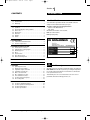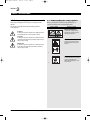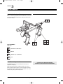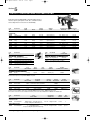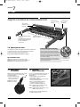
1
18-Flift-Cover4pp.ps
24/2/10
16:23
Page 18
Operating Instructions
Customer service
Tel:
01522 507550
Fax:
01522 689011
E-mail: [email protected]
19-Flift-Cover4pp.ps
24/2/10
16:01
Page 19
Spaldings Limited For customer service, Tel: 01522 507550 Fax: 01522 689011
Flift-OpInst-mono10
24/2/10
16:24
Page 1
Section
CONTENTS
1
1
INTRODUCTION
INTRODUCTION
1.0 Identification . . . . . . . . . . . . . . . . . . . . . . . . . . . . . . . 1
1.1 Warranty . . . . . . . . . . . . . . . . . . . . . . . . . . . . . . . . . . 1
1.0 Identification
2
SAFETY GUIDELINES
2.0 Symbols . . . . . . . . . . . . . . . . . . . . . . . . . . . . . . . . . . 2
2.1 Understanding the safety symbols . . . . . . . . . . . . . . 2
2.2 Before use: . . . . . . . . . . . . . . . . . . . . . . . . . . . . . . . . . 3
2.3 During use:. . . . . . . . . . . . . . . . . . . . . . . . . . . . . . . . . 3
2.4 After use: . . . . . . . . . . . . . . . . . . . . . . . . . . . . . . . . . . 3
2.5 Always: . . . . . . . . . . . . . . . . . . . . . . . . . . . . . . . . . . . . 3
2.6 Never:. . . . . . . . . . . . . . . . . . . . . . . . . . . . . . . . . . . . . 3
The label contains the following information:
– Address of the Manufacturer,
– “EU” mark,
A Identification number of the machine,
B Model of the machine,
D Weight (kilograms).
3
MAINTENANCE
3.0 Lubrication and maintenance . . . . . . . . . . . . . . . . . . 4
3.1 Shear bolt protection . . . . . . . . . . . . . . . . . . . . . . . . . 4
4
OPERATING INSTRUCTIONS
4.0 Connection to a tractor . . . . . . . . . . . . . . . . . . . . . . . 5
4.1 Adjusting the working depth . . . . . . . . . . . . . . . . . . . 5
4.2 Working speed . . . . . . . . . . . . . . . . . . . . . . . . . . . . . 5
4.3 Discs . . . . . . . . . . . . . . . . . . . . . . . . . . . . . . . . . . . . . 5
4.4 Packer rollers . . . . . . . . . . . . . . . . . . . . . . . . . . . . . . 5
4.5 Checking for wear . . . . . . . . . . . . . . . . . . . . . . . . . . . 5
4.6 General working hints . . . . . . . . . . . . . . . . . . . . . . . . 6
5
SPECIFICATIONS & OPTIONS LISTING . . . . . . . . . . . .7
6
PARTS LISTING . . . . . . . . . . . . . . . . . . . . . . . . . . . . . . . .8
7
OPTIONS
7.0 Spiked packer roller . . . . . . . . . . . . . . . . . . . . . . . . . 9
7.1 Depth wheel assembly . . . . . . . . . . . . . . . . . . . . . . . . 9
7.2 Hydraulic depth control kits . . . . . . . . . . . . . . . . . . . 9
7.3 Hydraulic auto-trip legs . . . . . . . . . . . . . . . . . . . . . . 10
7.4 Mole conversion kits . . . . . . . . . . . . . . . . . . . . . . . . 10
7.5 Disc cultivation tool bar . . . . . . . . . . . . . . . . . . . . . . 11
7.6 Tine cultivation tool bar . . . . . . . . . . . . . . . . . . . . . . 11
7.7 Tool bar replacement parts . . . . . . . . . . . . . . . . . . . 12
7.8 Air seeding units . . . . . . . . . . . . . . . . . . . . . . . . . . . 13
8
You can find the registration number of the Flatlift® subsoiler
stamped on the identification label (see Fig.1).
A
B
C
Fig.1 Identification plate
YEAR FRAME
5
WARRANTY
1.1 Warranty
All Flatlift® frames are guaranteed against bending or breaking for
FIVE YEARS from the date of purchase, providing the implement
has not been abused and that no more than the recommended
horse power has been used.
This warranty does not cover normal wear such as erosion of
paint finish, distortion of linkage pin holes, etc.
SINGLE-PASS TOOL BARS
8.0 Tool bar to Flatlift attachment . . . . . . . . . . . . . . . . . 14
8.1 Tool bar operation and adjustment . . . . . . . . . . . . . 15
8.2 Tool bar maintenance . . . . . . . . . . . . . . . . . . . . . . . 15
8.3 Tool bar specification . . . . . . . . . . . . . . . . . . . . . . . 15
e-mail: [email protected] visit: www.spaldings.co.uk
1
Flift-OpInst-mono10
Section
24/2/10
16:24
Page 2
2
SAFETY GUIDELINES
2.0 Safety warning signs
2.1 Understanding the safety symbols
Safety signs are applied to the machine to indicate potential
dangers.
Before operating the machine, it is important that each
operator understands the following explanations.
The operator must fully understand the warning symbols
on the machine:
Safety symbol
Symbol meaning
BEFORE MAINTENANCE
1. Important, carefully read the
manufacturers handbook before
attempting maintenance.
DANGER
To draw the operator’s attention to situations which
could endanger his or other peoples safety.
CAUTION
To draw the operator’s attention to situations which
could affect the machine performance but not his or
other peoples safety.
1.
DANGER OF FOOT INJURY
2. Any person near the machine
when working must keep a safe
distance.
IMPORTANT
To draw the operator’s attention to situations which
do not affect the machine performance and his or
other peoples safety.
2.
LIFTING GEAR
3.
2
3. When lifting the machine always
use appropriate lifting gear
attached to the lifting eyes on the
machine frame.
Spaldings Limited For customer service, Tel: 01522 507550 Fax: 01522 689011
Flift-OpInst-mono10
Section
24/2/10
16:24
Page 3
2
SAFETY GUIDELINES
2.2 Before use:
• Ensure operators have read and are familiar with the
instructions contained in this manual.
• Ensure that the Flatlift® is level and stable. The parking prop
should be lowered and support blocks used where necessary.
• Consult the tractor manufacturer’s manual for instructions on
safe mounting of implements and working methods.
2.5 ALWAYS:
•
•
•
•
Wear substantial or safety footwear.
Wear gloves when handling worn parts with sharp edges.
Ensure the Flatlift® is not operated by untrained persons.
Use the Flatlift® only for the purpose for which it was designed
and tested and in accordance with the guidelines in this
manual.
• Interpret “right” and “left” as the right and left of the operator
facing forward in the tractor cab.
2.3 During use:
• Ensure the Flatlift® is correctly attached to the tractor and the
parking prop is raised.
• Be alert to underground obstructions, e.g. tree roots, cables,
boulders, pipes, etc. Should an obstruction be encountered,
stop immediately and investigate.
• Ensure all persons are well clear of the Flatlift® whilst in use.
• Observe safe driving procedures, e.g. reducing speed on
slopes and sharp turns.
• Never turn corners with the Flatlift® in the ground.
2.6 NEVER:
• Carry out adjustments or repairs to the Flatlift® unless the
tractor engine is stopped and the Flatlift® is firmly supported or
lowered to the ground.
• Leave the tractor cab unless the Flatlift® is lowered, the tractor
gear shift is in neutral, the brake applied, the engine stopped
and the ignition key removed.
• Allow persons to ride on the Flatlift® during operation and
transportation.
2.4 After use:
• Check that all fasteners are tight.
• Carry out all lubrication and maintenance work as detailed in
this manual.
e-mail: [email protected] visit: www.spaldings.co.uk
3
Flift-OpInst-mono10
Section
24/2/10
16:24
Page 4
3
MAINTENANCE
3.0 Lubrication & maintenance
Before commencing any lubrication and maintenance ensure that
you have read and are familiar with the safety precautions at the
front of this manual.
D
250
D
KEY TO SYMBOLS
D
All models
TIGHTEN NUTS AND BOLTS
GREASE
TORQUE 1 bf/in. (SPECIFIED)
DAILY
3.1 Shear bolt protection
Flatlift®
The
swivel tines are shear bolt protected except on
hydraulic Auto-trip legs.
FAILURE TO USE GENUINE SPALDINGS
SHEAR BOLTS MAY INVALIDATE LEG WARRANTY
When replacing shear bolts, all adjacent parts such as shear
bushes and hinge plates must be checked and replaced if worn.
It is essential to use the shear bolts specified, failure to do so will
invalidate any subsequent warranty claims.
4
Spaldings Limited For customer service, Tel: 01522 507550 Fax: 01522 689011
Flift-OpInst-mono10
Section
24/2/10
16:24
Page 5
4
OPERATING INSTRUCTIONS
4.0 Connection to a tractor
4.3 Discs
1. Back the tractor up to the Flatlift®, which should be on a firm,
level surface. Position the Tractor lower links in line with the
Flatlift® lower mounting brackets.
2. The linkage pin holes selected will depend on the category of
linkage, the depth of work, the lifting capacity of the tractor and
the height of the tractor three point linkage from the ground.
Adjust the tractor top link to fit the Flatlift®, fit the linkage pins
and secure using a linch pin.
3. To disconnect the Flatlift® from the tractor, reverse the above
procedure.
4. When using the Flatlift® with discs fitted to the front leg, the
drawbar should always be removed.
Discs are recommended for working in grass or heavy trash
conditions. Discs can be fitted to all the current range of machines
and can be supplied either as original equipment, or later as
required.
4.1 Adjusting the working depth
Depth is controlled and adjusted by the setting of the top links on
the packer roller. In most conditions the Flatlift® frame should be
set parallel with the ground, however it may be necessary to
shorten the top link if penetration is difficult due to adverse
conditions.
4.2 Working speed
Forward working speed is not critical and, in general, the faster the
speed the greater the soil shatter effect, but this is obviously
dependant upon all the many factors that can affect the soil and
working conditions.
Discs can be adjusted for depth independently by slackening the
disc clamp screw and raising or lowering the disc. The clamp
screw must be securely tightened onto the disc post before
commencing work.
4.4 Packer rollers
Packer rollers are available for all models. Please refer to pages 7
and 9 within this book.
For further details contact your local Spaldings representative or
telephone our Sales Office: 01522 507600
or email: [email protected]
4.5 Checking for wear
The operator should check the tine wearing parts frequently and
should replace worn items as follows:
POINTS
Change prior to side or underside of tongue wearing.
WINGS
Change prior to side or underside of wing bracket wearing.
SHIN
Change prior to side of shank wearing.
SPECIAL NOTES
1. The swivel action of the tine is designed to cope with side
stresses caused by soil expansion and allows the tines to
pass around limited obstructions.
2. The Flatlift® is not designed to be turned whilst in work.
Always lift the implement when turning at headlands.
e-mail: [email protected] visit: www.spaldings.co.uk
5
Flift-OpInst-mono10
24/2/10
16:24
Page 6
4
Section
OPERATING INSTRUCTIONS
4.6 General working hints
WORKING REQUIREMENT
TINE CENTRE SETTINGS
1. Very thorough soil shatter.
Working in light soil.
– Set tine centres closer.
2. Deep or shallow work in soil that may
be liable to excess surface disturbance
due to over cultivation.
– Set tine centres wider.
3. Work in highly compacted areas,
e.g. tramlines, potato row bottoms and
trailer wheelings.
– Set tine centres wider.
HEAVY LAND
When working deep in some very difficult heavy land, with limited
horse power, it may be necessary to remove a tine or work the
land at a shallower depth in one direction then cross the land,
working at a greater depth.
PENETRATION
In most conditions the Flatlift® frame should be set parallel with
the ground, however it may be necessary to shorten the top link if
penetration is difficult due to adverse conditions.
6
Spaldings Limited For customer service, Tel: 01522 507550 Freefax: 0800 716040
Flift-OpInst-mono10
Section
24/2/10
16:24
Page 7
5
FLATLIFT® SPECIFICATIONS & OPTIONS LISTING
Both 2.85m and 3.5m width Flatlifts can be fitted with a range of
machine options; spiked packer roller, discs, cultivation tool bar
and seeding unit, for increased choice and flexibility.
PROD.
NO.
DESCRIPTION
FRAME
WIDTH
LINKAGE
CATEGORY
WEIGHT
WORKING
DEPTH
WORKING WIDTH
BETWEEN mm
WING SIZE
mm
FLATLIFT MACHINES
2.85m width
12825
3 Leg
2.85m
638kg
cat. 2 & 3
up to 43cm (17")
762 – 838 (30 – 33")
150 (6")
12906
3 Leg auto-trip
2.85m
872kg
cat. 2 & 3
up to 43cm (17")
762 – 838 (30 – 33")
150 (6")
12977
4 Leg
2.85m
-
cat. 2 & 3
up to 43cm (17")
610 (24")
150 (6")
3.5m width
12944
4 Leg
3.5m
699kg
cat. 3
up to 43cm (17")
660 (26")
150 (6")
12945
4 Leg auto-trip
3.5m
-
cat. 3
up to 43cm (17")
660 (26")
150 (6")
12791
5 Leg
3.5m
805kg
cat. 3
up to 43cm (17")
762 – 838 (30 – 33")
150 (6")
12907
5 Leg auto-trip
3.5m
1194kg
cat. 3
up to 43cm (17")
762 – 838 (30 – 33")
150 (6")
12947
7 Leg
3.5m
1017kg
cat. 3
up to 43cm (17")
380 (15")
150 (6")
12948
7 Leg auto-trip
3.5m
-
cat. 3
up to 43cm (17")
380 (15")
150 (6")
PROD.
NO.
DESCRIPTION
PROD.
NO.
DESCRIPTION
TO FIT
FLATLIFT MODEL
AUTO-TRIP LEG KITS
DEPTH WHEELS & TRASH DISCS
12903
3 Leg auto-trip conversion kit
02188
R.H. Depth wheel
All models
12946
4 Leg auto-trip conversion kit
02189
L.H. Depth wheel
All models
12988
5 Leg auto-trip conversion kit (2 beam)
12832
12905
5 Leg auto-trip conversion kit (3 beam)
Heavy duty trash disc assembly
(one required per leg).
All models
12949
7 Leg auto-trip conversion kit
PROD.
NO.
DESCRIPTION
TO FIT
FLATLIFT MODEL
DEPTH
CONTROL
TOTAL
WIDTH
PACKER
DIAMETER
OPTIONAL
HYDRAULIC DEPTH CONTROL
SPIKED PACKER ROLLER
12829
Packer
3 – 4 leg
top link
2.85m
405mm (16")
02330
12802
Packer
4 – 7 leg
top link
3.5m
405mm (16")
02332
Packer roller to fit pre-2006 3 leg Flatlift: 02288 2.6m packer.
PROD.
NO.
DESCRIPTION
TO FIT
FLATLIFT FRAME
CULTIVATION
ASSEMBLIES
OPTIONAL
CULTI-WING
OPTIONAL
DEFLECTOR KIT
OPTIONAL
ERAD. TINE KIT
-
CULTIVATION TOOL BARS
12960
Disc tool bar
2.85m
10 R.H & 10 L.H disc assemblies
-
12830
12961
Disc tool bar
3.5m
12 R.H & 12 L.H disc assemblies
-
12830
-
12827
Tine tool bar
2.85m
5 tine assemblies
19077
12830
12833 (7 tine)
12793
Tine tool bar
3.5m
6 tine assemblies
19077
12830
12808 (8 tine)
Tool bars are also available to fit pre-2006 3 leg Flatlift: 12962 2.6m disc tool bar. 12762 2.6m tine tool bar.
Disc tool bar conversions are also available to retro-fit to pre-2009 tool bars: 12963 2.85m. 12964 3.5m. 12965 2.65m.
PROD.
NO.
DESCRIPTION
TO FIT
FLATLIFT MODEL
OIL SEED RAPE
SEEDING RATE
HOPPER
CAPACITY
SEED
OUTLETS
Flatlift & other 3 – 3.5m subsoilers etc
for rape seeding into cultivated top soil
from 2.4 – 17kg per hectare
100 ltrs
4
4 – 7 leg Flatlift machines,
from 2.4 – 17kg per hectare
for rape seeding directly behind subsoil legs
200 ltrs
up to 8
AIR SEEDING UNITS
Standard Seeder
12834
Air seeding unit
Narrow Band Seeder
12950
Air seeding unit
e-mail: [email protected] visit: www.spaldings.co.uk
7
Flift-OpInst-mono10
Section
24/2/10
16:24
Page 8
6
FLATLIFT® PARTS LIST
ILLUS.
NO.
DESCRIPTION
SPALDINGS
PROD. NO.
FLATLIFT® LEG ASSEMBLY
Diamond Bar Frames
A and B
A1 – 6
A1
A4
A5
A6
A2
A3
-
A2
A3
-
A7
A7
A8
A10
A9
A11
A12
Leg assembly c/w swivel box and all wearing parts . . . . . 02194
Leg c/w wearing parts . . . . . . . . . . . . . . . . . . . . . . . . . . . . 02359
34" Leg c/w connecting tongue and wing brackets . . . . . 02170
Point . . . . . . . . . . . . . . . . . . . . . . . . . . . . . . . . . . . . . . . . . . 02154
M10 x 35mm roll pin – fits point & lower shin (Pack of 10) 02334
Lower reversible shin . . . . . . . . . . . . . . . . . . . . . . . . . . . . . 02153
Upper reversible shin . . . . . . . . . . . . . . . . . . . . . . . . . . . . . 02152
M10 x 25mm roll pin – fits upper shin (Pack of 10) . . . . . . 02329
Flatlift punch for roll pins . . . . . . . . . . . . . . . . . . . . . . . . . . 12760
6" Wing (2 hole) R.H . . . . . . . . . . . . . . . . . . . . . . . . . . . . . . 02168
6" Wing (2 hole) L.H . . . . . . . . . . . . . . . . . . . . . . . . . . . . . . 02169
1⁄2" x 40mm HT Bolt and nut (Pack of 10) . . . . . . . . . . . . . . 09216
Durafaced® 6" wing (2 hole) R.H. . . . . . . . . . . . . . . . . . . . D2168
Durafaced® 6" wing (2 hole) L.H . . . . . . . . . . . . . . . . . . . . D2169
1⁄2" x 40mm HT Bolt and nut (Pack of 10) . . . . . . . . . . . . . . 09216
Durafaced® weld-on leg wear plate R.H. (190 x 190mm) . D2016
Durafaced® weld-on leg wear plate L.H. (190 x 190mm). . D2038
Weld-on lower shin tongue (Pre 2000 legs) . . . . . . . . . . . 02261
Weld-on point tongue. . . . . . . . . . . . . . . . . . . . . . . . . . . . . 02276
Connecting tongue (Pre 2000 legs). . . . . . . . . . . . . . . . . . 02175
Weld-on wing bracket unit (2 hole) R.H. & L.H. complete . . . 02171
Leg bush. . . . . . . . . . . . . . . . . . . . . . . . . . . . . . . . . . . . . . . 02287
A
Flatlift® Punch
12
12760 3⁄8" x 200mm
parallel punch.
6
1
7
5
11
9
8
3
4
10
2
19
16
FLATLIFT® HINGE ASSEMBLY
Diamond Bar Frames
FLATLIFT® DISC ASSEMBLY
Diamond Bar Frames
-
Heavy duty disc assembly
(one assembly required per leg) . . . . . . . . . . . . . . . . . . . .12832
20" Fluted disc only . . . . . . . . . . . . . . . . . . . . . . . . . . . . . . 02207
Disc set screw M12 x 20mm (Pack of 10) . . . . . . . . . . . . . 12836
Disc post arm . . . . . . . . . . . . . . . . . . . . . . . . . . . . . . . . . . . 12838
Spindle shaft. . . . . . . . . . . . . . . . . . . . . . . . . . . . . . . . . . . . 12835
Disc bearing kit for forks. . . . . . . . . . . . . . . . . . . . . . . . . . . 12839
FLATLIFT® DEPTH WHEEL ASSEMBLY
Diamond Bar Frames
C1
-
R.H. assembly (for 3 Leg Flatlift & . . . . . . . . . . . . . . . . . . . 02188
post 2008 model 4, 5 & 7 leg Flatlift)
L.H. assembly (for 3 Leg Flatlift & . . . . . . . . . . . . . . . . . . . 02189
post 2008 model 4, 5 & 7 leg Flatlift)
Depth wheel bearing kit A . . . . . . . . . . . . . . . . . . . . . . . . 12756
1 x 30206 taper roller bearing (30 x 62mm), 1 x 30209 taper roller
bearing (45 x 85mm), 1 x Dust seal (45 x 85mm).
Wheel bearing kit B . . . . . . . . . . . . . . . . . . . . . . . . . . . . . 12757
1 x 30206 taper roller bearing (30 x 62mm), 1 x 30208 taper roller
bearing (40 x 80mm), 1 x Dust seal (40 x 80mm).
Depth wheel hub cap only . . . . . . . . . . . . . . . . . . . . . . . . . 12769
LINKAGE PINS
D1
D2
D3
8
NB. Grooved shear
bolts; check type of
hinge boss, bush and
groove position ‘x’ for
correct fit
20
A13 – 20 Hinge assembly . . . . . . . . . . . . . . . . . . . . . . . . . . . . . . . . . 02361
A13
Hinge . . . . . . . . . . . . . . . . . . . . . . . . . . . . . . . . . . . . . . . . . 02178
A14
Bottom clasp plate . . . . . . . . . . . . . . . . . . . . . . . . . . . . . . . 02180
A15
Top clasp plate . . . . . . . . . . . . . . . . . . . . . . . . . . . . . . . . . . 02179
A16
Hinge pin, spring washer and nut . . . . . . . . . . . . . . . . . . . 02182
A20
Stepped shear bolt bush (for square bossed hinge) . . . . 02297
A17
M16 x 100mm shear bolt (grooved: x =23.5mm)
for square bossed hinge (Pack of 10). . . . . . . . . . . . . . . . . 08719
A18
Pivot bolt M24 x 130mm (for Square bossed hinge). . . . . 02224
A19
Clasp bolt M20 x 260mm c/w nut and spring washer . . . . 02181
B1
For Flatlift roll pins.
Top link pin. 160mm Category 2. . . . . . . . . . . . . . . . . . . . 02341
Lower link pin. 170mm Category 2. . . . . . . . . . . . . . . . . . . 02356
Top link pin. 160mm Category 3. . . . . . . . . . . . . . . . . . . . . 02339
Lower link pin. 270mm Category 3. . . . . . . . . . . . . . . . . . . 02340
Lower link pin. Category 2/3 stepped to fit
post 2008 model, 3 leg machines . . . . . . . . . . . . . . . . . . . 12957
15
Heavy duty
square boss
18
13
17
14
B
The heavy duty disc
assembly will fit all
diamond bar Flatlifts.
For the perfect finish to
grassland or to cut
through straw and trash
in arable applications
1
C
1
D
1
2
3
Spaldings Limited For replacement parts, Tel: 01522 507600 Freefax: 0800 716040
Flift-OpInst-mono10
Section
24/2/10
16:24
Page 9
7
OPTIONS
depth control & consolidation
Adjustable packer
scrapers for maximum
cleaning
16" Diameter Packer
Roller for efficient
consolidation
Vertical scraper
mountings let trash
fall through
YEAR FRAME
5
WARRANTY
Supplied with adjustable top links
as standard
Full working width for
efficient consolidation
OPTIONAL hydraulic depth control
allows the Flatlift working depth to
be adjusted effortlessly –
see below (7.2)
7.0 Spiked packer roller
IN THE EVENT OF A BLOCKAGE:
The spiked packer roller provides depth control with consolidation and
is essential for moisture conservation and rapid seed germination.
Suitable for both arable and grassland applications.
For specification and product numbers see page 7
REPLACEMENT PARTS
02599 Steel scraper (post-1996 models). Single.
18917 M8 x 30mm HT coach bolt & lock nut. Pack of 10.
12958 Packer roller bearing (post-2006 models).
Loosen the rear most bolts on the scraper beam (A),
undo the front bolts (B), removing the nuts whilst
leaving the bolts in position. Pull on the fully retracted
packer stands to take the weight of the scraper beam
and remove the front bolts (B) one at a time. With the
bolts fully removed pull the stand to swivel the beam
over on the rear bolts (A).
Tighten the rear bolts fully to ensure the beam does
not move whilst cleaning. Reverse the procedure to
return the beam to normal.
7.1 Depth wheel
assemblies
7.2 Hydraulic
depth control kits
Fitted to the frame, and designed for basic depth
control, these units are more often used in
grassland applications.
• Allows the Flatlift’s working
depth to be set without the
need of a packer roller
The conversion kit simply attaches to the spiked
packer roller in place of the existing manual
adjusting links.
• Allows the Flatlift’s working depth to be
adjusted while on the move
• Saves operator downtime – less effort needed
than with manual adjustment
• Ensures optimum Flatlift productivity as
conditions and soil types change
• c/w all necessary fittings and pipework
02188 R.H. assembly.
02189 L.H. assembly.
A B
De-mountable scraper
assembly allows easy
access for cleaning
02330 Hydraulic depth control kit to fit 3 leg
Flatlift spiked packer rollers.
02332 Hydraulic depth control kit to fit 4 – 7 leg
Flatlift spiked packer rollers.
The minimum tractor hydraulic requirement is
one double acting spool valve.
e-mail: [email protected] visit: www.spaldings.co.uk
9
Flift-OpInst-mono10
Section
24/2/10
16:24
Page 10
7
OPTIONS
7.3 Hydraulic auto-trip legs
Auto-trip Heavy duty hydraulic ram
pressurised by a hydro-pneumatic
accumulator allows the leg to
trip back
The Flatlift® auto-trip leg comes into its own in the
more stony and rocky areas of the country;
dramatically saving downtime.
No shear bolts means no need to leave the cab –
the pressurised system automatically re-sets the
Flatlift® leg.
Ball joint ram design maintains
the Flatlift legs unique capacity
to swivel – reducing side stress
For specification and product numbers
see page 7
NO shear bolts to replace!
“Subsoiler trip leg minimises downtime”
Perth-based arable farmer Graham Reid says
pressure on autumn workloads and labour
availability, coupled with a limited number of days
for autumn cultivations means he cannot afford
downtime or less than ideal soil conditions for
crop establishment.
The Farm’s 2000 acres of cropped land has a
variety of soil types including heavy clay, medium
loam and light lands. Cropping includes winter
cereals as well as potatoes and carrots.
“We have tried various one pass systems,” says
Mr Reid. “But we find our best results come after
ploughing.” To aid drainage and ploughing, 300 –
400 acres are subsoiled each year during August
and September.
This is carried out using a Spaldings Flatlift fitted
with auto-trip legs to a depth of 12 – 14 inches,
pulled by a 130hp John Deere.
“Before auto-trip was available on the Flatlift it
was not uncommon to replace at least 20 shear
bolts per day on the stronger land, easily taking
two hours out of a working day – downtime we
simply could not afford.”
“We fitted the auto-trip system ourselves, which
involved quite a lot of welding,” he says. “We
also have the disc cultivation tool bar for going
into old potato land in front of the drill.”
“Auto-trip means we can increase our forward
speed, but the real beauty of the system is that
we don’t have to keep getting on and off the
tractor to replace shear bolts.
The fact that the legs also swivel means that they
are not rigid if they hit something solid rather
than lifting out of the ground along with whatever
has been hit.” Mr Reid says “It just does not
make sense not to have one, especially on our
soil types up here.”
7.4 Mole drainer conversion leg
A simple, cost effective way of converting your FLATLIFT® from a
subsoiler into a mole drainer.
02200 Mole conversion for diamond bar
Flatlift machines. Consisting of:
1 x 02198 Flatlift mole hinge (A),
1 x 01185 single ended 40" x 8" x 1"
mole blade (B),
1 x 01187 3" x 26" mole foot (C),
1 x 01188 31⁄2" expander (D),
1 x 01191 coupling (E),
3 x 01190 M20 x 65mm double roll pins,
1 x 07594 M20 x 100mm 8.8 grade
shear bolts (pack of 5),
1 x 07058 M20 x 100mm 10.9 grade
pivot bolt.
A
B
D
12928 Replacement bush for mole hinge.
E
C
10
Auto-trip legs can be
retro-fitted to existing
machines or ordered
as standard with
new machines
It’s simple just remove the Flatlift leg from its hinge,
release the hinge pin, replacing the Flatlift hinge with
the new mole hinge and leg assembly.
Spaldings Limited For replacement parts, Tel: 01522 507600 Freefax: 0800 716040
Flift-OpInst-mono10
Section
24/2/10
16:24
Page 11
7
OPTIONS
Fitting between the Flatlift® legs and packer roller,
tool bars efficiently mix the top soil and crop
residue providing cost-effective single-pass soil
conditioning.
“tool bar single-pass savings”
A 3-leg Flatlift and cultivation tool bar is used
by Herefordshire farmer Mr Nigel Roper;
“I was particularly pleased with the job the Tool
Bar was doing, it adds another dimension to the
Flatlift” comments Nigel, “the Flatlift becomes a
one pass machine capable of subsoiling and
cultivating in one go with the obvious savings in
fuel, labour and compaction that another pass
would incur.
The wings and points have also shown little sign
of wear in our abrasive sandy soils.
save fuel, cultivation time and labour costs
7.5 Disc cultivation tool bar
NOW available with up to 24 disc units, the new
more efficient Disc tool bars cultivate to 4" with
adjustable working depth.
• Opposing hardened conical discs ensure
optimum mixing of top soil with surface trash
• Long and reliable working life is achieved
through shock absorbing rubber mounts
TOOL BAR OPTIONS:
SIDE DEFLECTOR KIT
For use with disc tool bars; rubber
deflector panels fit either side of the
packer frame to retain soil within the
working width for a neat finish.
7.6 Tine cultivation tool bar
Tine tool bars cultivate to 8" with adjustable
working depth. Heavy duty reversible points
fitted as standard, optional wings for greater
lift are also available.
YEAR FRAME
5
WARRANTY
For specification and product numbers see page 7
e-mail: [email protected] visit: www.spaldings.co.uk
ERADICATOR TINE KITS
Designed to fit the packer roller frame,
tine kits can be used with tine tool bars
for an extra level finish.
CULTIVATION WINGS
Can be fitted beneath the standard
points on tine tool bars for increased
penetration and soil disturbance.
11
Flift-OpInst-mono10
Section
24/2/10
16:24
Page 12
7
OPTIONS
7.7 Single-pass tool bar replacement parts
A
4
• Used with tine tool bars –
eradicator tines fit the
Flatlift packer roller
for an extra level finish
1
6
3
2
5
ILLUS.
NO. DESCRIPTION
ILLUS.
NO. DESCRIPTION
PROD.
NO.
A2
A3
A4
A5 6 Tine kit . . . . . . . . . . . . . 12786
A5 7 Tine kit . . . . . . . . . . . . . 12833
A5 8 Tine kit . . . . . . . . . . . . . 12808
Replacement parts
Ripper tine . . . . . . . . . . . 11344
2 hole point . . . . . . . . . . 05370
M10 x 70mm bolt & nut
(Pk 10) . . . . . . . . . . . . . . . 09192
Eradicator tine pin. . . . . 08880
Shear bolt & nut (Pk 10). 08881
4mm ‘R’ clip (Pk 30).. . . 07626
Eradicator tine bracket assembly
(fits 120 x 80mm). . . . . . 12790
Complete hub and bracket assembly R.H. for series 2
disc tool bar. . . . . . . . . . . . . . . . . . . . . . . . . . . . . . . . . . . . . . 12967
Complete hub and bracket assembly L.H. for series 2
disc tool bar. . . . . . . . . . . . . . . . . . . . . . . . . . . . . . . . . . . . . . 12968
16" cutaway disc for series 2 disc tool bar . . . . . . . . . . . . . . 12966
Bearing kit for series 2 disc tool bar . . . . . . . . . . . . . . . . . . . 12969
Rubber spring for series 2 disc bracket assembly
(4 required per assembly). . . . . . . . . . . . . . . . . . . . . . . . . . . 12970
B
ILLUS.
NO. DESCRIPTION
ERADICATOR TINES
DISC TOOL BAR series 2
Replacement parts
A1
PROD.
NO.
1
PROD.
NO.
TOOL BAR
Replacement parts
A6
A6
Centre bar for
2.85m tool bars . . . . . . . 12954
Bolt for 12954 . . . . . . . . 12956
Tool bar turnbuckle . . . . 12955
Tool bar end bracket
R.H. . . . . . . . . . . . . . . . . 12953
Tool bar end bracket
L.H. . . . . . . . . . . . . . . . . 12972
1
5
5
7
7
6
6
8
2
10
8
12
3
4
ILLUS.
NO. DESCRIPTION
11
9
PROD.
NO.
9
ILLUS.
NO. DESCRIPTION
PROD.
NO.
ILLUS.
NO. DESCRIPTION
PROD.
NO.
TINE TOOL BAR
Replacement parts
DISC TOOL BAR (Pre-2009)
Replacement parts
DEFLECTOR KIT
for Disc Tool Bars
-
-
Attach the rubber deflector panel to
either side of the Flatlift Packer
frame to retain surface soil within
the working width for a neat finish.
B12 Side deflector kit for
disc tool bars . . . . . . . . . 12830
Consists of 2 rubber deflectors
complete with fixings.
B12 Replacement rubber
deflector . . . . . . . . . . . . . 12831
B1
B2
B3
B4
B5
B6
B7
B8
B9
12
Complete cultivation tine assembly
c/w heavy duty point (items A1, 2 & 3). . . 12817
Replacement complete upper tine and
spring assembly . . . . . . . . . . . . . . . . . . . . . 12772
Replacement lower tine to fit 12772 . . . . . . 12763
Heavy duty reversible point . . . . . . . . . . . . 02107
7⁄16 x 65mm fastener to fit 02107
(Pack of 10) . . . . . . . . . . . . . . . . . . . . . . . . . 09207
One piece cultivator wing . . . . . . . . . . . . . . 19077
7⁄16 x 75mm fastener to fit 19077
(Pack of 10) . . . . . . . . . . . . . . . . . . . . . . . . . 09208
Frame to upper tine clamp (2 required). . . 12771
Upper to lower tine eye bolt and U-bolt . . . 12770
Pivot pin for 12772. . . . . . . . . . . . . . . . . . . . 12778
Bush for pivot pin 12778 (1 pair) . . . . . . . . 12777
Tube socket bush for 12772 (single) . . . . . 12776
Complete cultivation disc tine assembly
(items A1 & A10) . . . . . . . . . . . . . . . . . . . . 12816
B1 Replacement complete upper tine and
spring assembly . . . . . . . . . . . . . . . . . . . . . 12772
B10 Replacement lower tine c/w 460mm (18")
dual discs and hub assembly to fit 12772 . 12781
Lower tine only, to fit disc bracket . . . . . . . 12789
Hub & bracket assembly to fit 12781 . . . . . 12788
460mm (18") cuttaway disc . . . . . . . . . . . . 12787
Disc bearing kit to fit 12781. . . . . . . . . . . . . 12800
B11 Disc hub (single) c/w fasteners . . . . . . . . . 12919
B5 Frame to upper tine clamp (2 required). . . 12771
B6 Upper to lower tine eye bolt & U-bolt . . . . . 12770
B7 Pivot pin for 12772. . . . . . . . . . . . . . . . . . . . 12778
B8 Bush for pivot pin 12778 (1 pair) . . . . . . . . 12777
B9 Tube socket bush for 12772 (single) . . . . . 12776
Spaldings Limited For replacement parts, Tel: 01522 507600 Freefax: 0800 716040
Flift-OpInst-mono10
Section
24/2/10
16:24
Page 13
7
OPTIONS
7.8 Air seeding unit
A fluted roller system ensures that seed is delivered
evenly through air vents into cultivated soil.
A 12 volt electric drive fan provides airflow with
in-cab control, while the heavy duty landwheel
drive gives accurate ground speed metering.
100 litre seed hopper –
manufactured from seamless
polyethylene with rain proof
lid and rubber seal
12 volt electric drive fan
unit provides air flow with
in-cab on/off control
Tried and tested positive
displacement metering
system
Heavy duty landwheel
drive giving accurate
ground speed
metering
UNIVERSAL FITTING
Designed for the Flatlift, Spaldings air
seeding units can also be fitted to other
makes of 3m to 3.5m subsoilers and
cultivators (bracket modifications may
be required).
For specification and product
numbers see page 7
cost-effective seed placement
“Seeder unit cuts cost of oil seed
rape establishment”
A 3-leg Flatlift with tool bar and seeder unit is used
for rape establishment by Northants farmer
Mr Hutchinson. He describes how two main aims
guided him in the choice of a Flatlift seeder system.
“The primary motivation was to significantly reduce
our oil seed rape crop growing costs by combining
multiple operations into one and improve our soil
structure which is critical for oil seed rape.”
“In reality, subsoil conditioning, surface cultivation,
seeding and consolidation with just one tractor
and driver enabled us to remove several passes
from our rape establishment system. As well as
saving money the Flatlift legs shatter compaction
and help condition the soil structure getting the
crop off to the best possible start.”
“In fact crops sown with conventional multiplepass systems struggled significantly to germinate
as critical moisture was lost during multiple
cultivations in a difficult season.”
STANDARD AIR SEEDING UNIT –
suited to establishment systems
where a tilth is desirable (illustrated).
The standard seeding unit for use with
cultivation tool bars features a 100 litre
seed hopper with four seed outlets and
deflector plates to ensure seed is
spread accurately into cultivated soil
before the packer roller.
NARROW BAND AIR SEEDING UNIT
for oil seed rape – most suited to drier
conditions where minimum soil
cultivation is required.
The new seeder unit is based on the
existing positive displacement feed
roller design. It is available with two
100 litre hoppers and up to eight seed
outlets which deliver seed in bands
directly behind the subsoiler legs
before the packer roller.
NB. The air seeding unit is not
suitable for grass seed
Compare the difference !
Rape established
by traditional plough,
cultivation and drill
– poor growth
With the Flatlift tool bar and seeding unit,
establishment costs can be dramatically cut
in comparison to conventional plough and
cultivation systems.
Compared to traditional broadcast methods, the
Flatlift seeding unit gives superior seedling
establishment and tap root development for
increased yield potential.
Rape established by
Flatlift & seeding unit
– strong root with
excellent growth
• SAVE seedbed establishment costs
• SAVE cultivation time and labour costs
• SAVE fuel costs – reduced field work
• REDUCE soil compaction
Reduce the cost of oil seed rape establishment with Flatlift®
e-mail: [email protected] visit: www.spaldings.co.uk
13
Flift-OpInst-mono10
Section
24/2/10
16:24
Page 14
8
SINGLE-PASS TOOL BARS
8.0 Tool bar to Flatlift® attachment
Please note this procedure requires the use of suitable lifting
equipment.
1. If necessary remove packer roller from Flatlift®.
2. Securely attach slings to the tool bar, around the spring
assemblies, to enable the tool bar to be lifted in a safe level
manner.
3. Fit the eccentric bush in the upper front holes of the tool bar.
4. Lift the tool bar and offer up to the rear brackets of the Flatlift®.
5. Align the lower holes first and secure with the pins.
6. Align the top holes as close as possible using the forklift.
Using a pry bar, rotate and align the eccentric bushes and
secure with the pins.
DO NOT ATTEMPT TO ALIGN OR ROTATE THE BUSHES
USING FINGERS.
TOOL BAR
FLATLIFT®
Turnbuckle
Upper fixing holes
Eccentric bush
Packer mounting points
Lower fixing holes
Fig.2 Tool bar to Flatlift attachment
14
Spaldings Limited For customer service, Tel: 01522 507550 Fax: 01522 689011
Flift-OpInst-mono10
Section
24/2/10
16:24
Page 15
8
SINGLE-PASS TOOL BARS
8.1 Tool bar operation and adjustment
8.2 Tool bar maintenance
The working height of the tines or discs can be adjusted
independent to the Flatlift® and Packer as follows:–
Essential maintenance and operation points:–
1. First set the Flatlift® to the required working depth.
2. Slightly loosen the 4 clamp bolts at each end of the tool bar.
3. Rotate the turnbuckle on the side of the tool bar to either raise
or lower the tool bar as required. It is necessary to either turn
the adjusting bars simultaneously (requiring 2 people) or to turn
each bar a number of revolutions in sequence.
4. Once at the required height, re-tighten the 4 clamp bolts at
each end of the tool bar firmly.
5. UNDER NO CIRCUMSTANCES ATTEMPT TO USE THE TOOL
BAR WITHOUT THE CLAMP BOLTS FIRMLY TIGHTENED.
6. Once in operation observe the action of the tines and adjust the
spring tension screws so that a little movement can be
observed on the tines.
1. Grease turnbuckle screw threads and ensure that the thread is
kept protected with a coating of grease.
2. Grease the grease points daily
3. Ensure the end bolts on the height adjustment are kept tight at
all times.
4. Ensure the clamp bolts on the height adjustment are kept tight
at all times.
5. Check all tine assembly bolts on a daily basis.
6. Grease tine disc assemblies on a daily basis.
7. Replace any worn parts immediately.
End bolts x2
Fig.3 Tool bar adjustment
Clamp bolts x4
Turnbuckle
8.3 Tool bar specification
TOOL BAR
MODEL
L
DIMENSIONS
W
H
BARE FRAME
WEIGHT
WITH TINES
WITH DISCS
MAX WORKING DEPTH
WITH TINES
WITH DISCS
POWER REQ.
PER TINE / DISC
TOOL BARS
2.85m
1.2m
2.85m
1.54m tines
220kg
430kg
545kg
0 – 200mm (8")
0 – 100mm (4")
5 – 10hp
3.5m
1.2m
3.5m
1.45m tines
222kg
-
612kg
-
0 – 100mm (4")
5 – 10hp
e-mail: [email protected] visit: www.spaldings.co.uk
15
Flift-OpInst-mono10
24/2/10
16:24
Page 16
NOTES
16
Spaldings Limited For customer service, Tel: 01522 507550 Fax: 01522 689011
20-Flift-Cover4pp.ps
24/2/10
16:01
Page 20
e-mail: [email protected] visit: www.spaldings.co.uk
24/2/10
16:01
Page 17
www.spaldings.co.uk
Spaldings Limited, Sadler Road, Lincoln LN6 3XJ
Tel: 01522 507550 • Fax: 01522 689011
Spaldings (Ireland) Limited, Moydrum Business Park, Athlone, Co. Westmeath
Tel: 090 6486008 • Fax: 090 6486133
Flatlift Inst: 02.2010
17-Flift-Cover4pp.ps