1
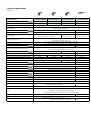
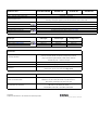
| Generation III Troubleshooting electric residential garage door operators DC800N-III DC650N-III DC550N-III Technical Data Sheet 20061128 Technical data KSY1000-868MHZ model name Maximum push and pull force 1000N KSY700-868MHZ KSY550-868MHZ DC800N-III DC650N-III DC550N-III 800N 650N 550N 150N Nominal force Interchangeable; chain or ultra quiet and maintenance-free Drive system Operator programming Diagnostic display (error message) Courtesy light KS0-240V-868W toothed cable or belt drive 3 buttons and double digit numerical display on motor head 3 buttons / LED Double digit numerical display on motor head 240V-40W (E14) lighting Time adjustable (2 - 240sec.) Yes 240V-40W (E14) lighting. 180 sec. 240V-40W (E14) lighting. 180 sec. Automatically learned for both open and close direction. Automatic safety cut-out Monitored and adjusted each cycle Push and pull force limit Automatic set and adjustable for both open and close direction Force 'offset' sensitivity Automatic set and adjustable for both open and close direction Short or full door reverse Programmable safety reverse Open and close door position settings No mechanical excess travel stop required Yes "Intermediate" door position Operator Speed Door travel speed Opening time (door specific) approximately Soft" start / "Soft" stop Automatic closing Quick Program automatic closing Photocell Closing edge safety device Programmable Impulse type External warning light Full reverse Electronically set and monitored with patented reference switch system. - Adjustable (maximum 140mm/sec) for both open and close direction Both open & close 140 mm/sec. 140 mm/sec. 120 mm/sec. 120 mm/sec. 15 sec. 15 sec. 18 sec. 20 sec. Adjustable ; "Off" / 200mm / 300mm / 400mm Adjustable (0-255 sec.) - 0 or 30 sec. - Preset automatic closing values - Class 3 self monitoring Can be connected - Yes - Can be connected via optional in- or external relay Can be connected via optional relay with equal time as courtesy light - Door open position signaling Can be connected via optional relay - Door closed position signaling Can be connected via optional relay - Additional lighting Electronic back drive (burglary) detection Connection possibility for alarm system Factory reset function Remote control Transmitter coding Automatic door closure when a 10mm motor back drive is detected Yes Yes 2 x 868MHz. 4-button mini transmitters - with wall holder and visor clip Digital multi-bit fail safe system with more than 268 Billion codes. DC self inhibiting worm gear motor with RPM sensor Motor Transformer with thermal overload protection Short-term duty: KB2min. IP20 protection; for dry rooms only Mains Stand-by consumption Dimensions (W x H x D) 230 / 240 V/AC, 50Hz., with CEE phase changer plug Approx. 3.9W Operator head KSY: 19.7 x 15 x 37.5 cm. Carton dimensions: 25 x 17 x 50 cm. 230 / 240 V/AC, 50Hz. Technical data KSY1000-868MHZ DC800N-III DC650N-III 30mm (35mm with rail clamp) Headroom required Automatic / adjustable Chain / Toothed Cable / Belt relief 1-piece pre-assembled or 2-piece semi assembled. Interchangeable boom Including rail support props to prevent direct tension onto motor shaft Strong durable steel chain Chain drive system Toothed cable system Maintenance free, ultra quiet and patented toothed cable Belt drive system Maintenance free, ultra quiet, steel reinforced toothed belt Yes Emergency release mechanism Mechanical carriage locking device (per 2008) Integrated door security kit Universal fitting for up-and-over and sectional doors Fitting Boom Type Rail length Overall length Carriage travel Short boom (308 series) 3080 mm. 3353 mm. 2590 mm. Medium boom (333-series) 3330 mm. 3603 mm. 2840 mm. Long boom (411-series) 4090 mm. 4363 mm. 3600 mm. Accessories Multibit transmitters - inter-changeable 868 or 433 MHz. Receivers Frequency operated external universal 24VDC or 240VAC (waterproof) receivers plug-in or build in light switches, tubular motor switches wireless bell push - wireless code pad Impulse 3-function console - bell push button - key switch - transponder Beam break - closing edge safety device - signal lights Safety Installation DC550N-III Door connector attachments for large, heavy sectional doors Fitments for up-and-over doors and wing doors Certification EN12453, EN292-1, EN 50081-1, EN 50082-1, EN 55014, EN 60335-1 EN60335-2-95, EN 12445, EN 61000-3-2, EN 61000-3-2 Norms and standard base ETS 300220, ZH494 April 89, VDE 0700-238 certificates EN 13241-1 per door brand available upon request EG Declaration of conformity EN 13241-1, EN 12453, EN 12445 89/106/EWG, 98/37/EG, 72/23/EWG, 89336/CEE Copyright. Subject to alterations in the interests of technical process. Rail (channel) overview Chain drive rail Type Article nr. Available in 2-piece Total assembled Rail Length Length Carriage Travel Short chain RCD308-1P 150077302 150077308 3353 mm 3080 mm 2590 mm Medium chain RCD333-1P 150077311 150077317 3603 mm 3330 mm 2840 mm Long chain RCD411-1P 158011177 150066794 4363 mm 4090 mm 3600 mm Rail Length Carriage Travel Belt drive rail Type Article nr. Total Available assembled in 2-piece Length Short belt RBD308-1P 150077303 150077309 3353 mm 3080 mm 2590 mm Medium belt RBD333-1P 150077312 150077319 3603 mm 3330 mm 2840 mm Long belt RBD411-1P 158011182 150066795 4363 mm 4090 mm 3600 mm Rail Length Carriage Travel Toothed Cable rail Type Article nr. Available in 2-piece Total assembled Length Short rail RTC308-1P 150077304 150077310 3353 mm 3080 mm 2590 mm Medium rail RTC333-1P 150077316 150077320 3603 mm 3330 mm 2840 mm Subject to change and techniocal alterations Based on KSY motor head and maximum measurements | Explanation Explanation AUTOMATIC FORCE CONTROL SYSTEM Our motor heads have a state-of-the-art Force Control System for optimal safety. It automatically learns and sets up and down force sensitivity settings during initial cycles. The patented power limit is a plus for security. We have an extremely high level of sensitivity. Electronics monitor the moving door at every point of its travel. Unlike other control systems our operator recognizes at every position of the door, how much force is normally required to move it. If the door meets an obstacle, the operator reacts more quickly than a conventional operator. Electronics ‘learn’ maximal required force at each travel point of door (red line). An offset value will be added to set a “learned power limit” (yellow line). This increased value is needed to accommodate changes in i.e weather conditions (storm, cold, etc). The manually set power limit (purple line) is an extra operational safety. Once automatic ’learned power limit’ exceeds the ‘manually set maximum power limit’ the safety systems will be activated. Limit cam on chain or belt The limit cam on either chain or belt is ‘the heart’ of the operator. Each cycle the cam passes the limit switch. This is the so-called “time zero” point from which the operator electronics start counting. Meaning Time zero + 3,28 sec. = door open position. It also enables the operator to exactly know where it is (required for self learned force). Below chart indicates the actual measured force required to open and close a ‘regular’ residential sectional door. This indicates why variable automatic force setting is required to have an operational safe automatic garage door operator. MEASURED FORCE OF A RESIDENTIAL SECTIONAL GARAGE DOOR: While opening While closing Our garage door operators do meet the CE norms. For example, one of the norms requires a garage door to reverse within 1 second with having a static force never exceeding 400N. Measured force at 300mm. from bottom of sectional door. CE testing according to EN 12445 and EN 12453: | Troubleshooting LIMIT CAM POSITION (REFERENCE POINT CLIP) In case you have to install a new limit cam on to your chain, please follow below instructions. It is only possible to install a clip onto a chain. When you have a belt drive boom, it is not possible to reinstall a limit cam. Motorhead side Reference point clip should be 960 mm (+/- 30 mm) from motorhead side Carriage Chain clip can be manually connected. Belt clip can only be factory installed Limit clip Door side Before connecting the reference point clip, the carriage must be at max. front (door side) position. Troubleshooting DC550N-III There are many reasons why a consumer experiences a ‘problem’ with the door operator. It is up to logic thinking of customer service representative to pin-point the problem. However, we as manufacturer, have implemented a more than simple diagnostic system in all our garage door operators. When a consumer calls with a problem the first questions should always be: briefly and add the numbers inside LED’s.? Please press Our operators are set up with so-called error numbers. Each LED has an icon and a . The sum of numbers displayed in LED icon number in it’s display: for example indicate error. A sample questionnaire to diagnose problem over the phone: glow? 1. Does If not, there is no power! light up briefly during an opening or closing cycle? 2. Does If not, the Limit cam on chain or belt is missing or installed incorrect. 3. Door does not close and reverse? (Safety systems causes door to reverse) 4. Door does not open; it stops? (Safety systems causes door to stop when opening) Error 5: The automatic set maximum force (power limit or cut-out) is too low Error 8: Offset learned force is too sensitive (learned power curve or limit) 14/11/2007 remark When one is not able to store the door open position (Menu 1 Basic Settings) because Programming automatically quit > (LED 3 flashes indicating an error). When pressing P button (<1sec.) and when Error message 7 (LED 3 + LED 4) is indicated, it implicates the limit cam did not initiate the limit switch. Check limit cam on drive system (chain, belt or toothed cable) and check installation. TROUBLESHOOTING DC550N-III Fault Cause Remedy Indicator 4 does not glow. No voltage. Check mains supply. Check electric socket. Thermal protection in mains transformer Allow mains transformer to cool down. activated. Defective control unit. Cut off mains supply to operator. Remove lamp cover and motor cover. Unscrew control unit, pull slightly forward and withdraw the connecting plug. Remove control unit and have it checked. Indicator 3 flashes. Error 5 or 8 Automatic cut-out set too sensitively. Door operation too sluggish. Door blocks. Re-set automatic cut-out to be less sensitive (<, Menu band cpage 20). Ensure door moves easily. Indicator 3 flashes. Error 3 or 7 External photocell defective or interrupted. Remove obstruction or have photocell checked. Door open position (Basic settings Menu 1) can not be set and is automatically aborted. Error message 7 is indicated. Reference point is not initiated during programming cycle. Check limit cam on drive system. Run door to closed position before setting door open position. Check if reference point is initiated: LED 3 should illuminate for approximately 1 sec. during cycle. Drive only operates in "OPEN" but not in "CLOSE" direction. Error 7 Photocell programmed, but not connected (<, Menu a page 20). Reprogramme photocell function or connect photocell. No response on impulse. Indicator 3 glows. Connecting terminals for "IMPULSE" button bridged, e.g. due to short-circuit or wrong terminal connection. Temporarily isolate cabled key switches or interior push buttons from control unit. Remove plug, insert plug and look for cable fault. No response on impulse. Error 10 Short-circuit label removed, but "STOP" button not connected. Connect "STOP" button. Indicator does not flash rapidly on impulse from hand transmitter Hand transmitter coding is not consistent with receiver coding. Check coding Menu c, page 13. Flat battery. Insert new battery. Flashing LED in transmitter indicates battery condition. LED 3 does not light up when pressing transmitter button Electronic aerial not connected or wrong installation Hand transmitter or control unit defective. Have both components checked. Insufficient range of remote control (less than 5 m). Flat battery in hand transmitter. Indicator 3 flashes. Error 10 RPM sensor defective. Insert new 12V A 23 battery. Flashing LED in transmitter indicates battery condition. Have operator checked. Door too sluggish. Check door. Transmitter command does not respond but wall control does (LED 4 on, LED 3 flashes) Operator is in electronic 'vacation' lock DC550N-III De-activate 'vacation' lock on 3-function wall console or by briefly pressing % button on operator. ERROR MESSAGES DC550N-III When LED H is flashing the error message can be retrieved by pressing % briefly. The total sum of numbers in blinking LEDs indicate the so-called error number. LED flashes erratically Error number Fault H 3 Photocell actuated S 1 Programming aborted F 2 Reference point switch defective K 4 Defective RPM sensor Anti-lock system actuaed K+S 5 Power limit K+H 7 Excess travel stop K+H 7 Photocell self-monitoring unit not o.k. K+H 7 Reference point not initiated during Menu 1 settings K<−>H 7 Voltage monitoring is active K+H+S 8 Power limit self-monitoring unit K+H+S 8 Learned power limit K+H+S 8 Response sensitivity of power limit K+H+F+S 10 NC contact (Terminal 7&8) broken Troubleshooting DC650N/800N-III There are many reasons why a consumer may experience a ‘problem’ with the garage door operator. It is up to logic thinking of customer service representative to pin-point the problem. However, we as manufacturer, have implemented a more than simple diagnostic system in all our garage door operators. When the garage door operator detects an malfunction the letter will flash indicating an error. By pressing the programmation button an error number will be indicated. This error number will indicate particular malfunction. 10. Troubleshooting DC650N-III and DC800N-III Malfunctions without error message Error Nr. 1 of Nr. 18 does not light up. No reaction on impulse. Cause Solution - no voltage. - check if mains power supply is available. - check mains socket. - thermal overload protection in power transformer activated. - allow power transformer to cool down. - defective control unit. - check operator. - connection terminals for "impulse" - separate possibly connected key switches or interior pushbuttons from button were by-passed, e.g. due to a the control unit. short-circuit or flat terminals. - modular antenna is not inserted. - connect antenna with the control unit. - hand transmitter coding does not correspond to the receiver coding. - check coding. - Activate hand transmitter again. - hand transmitter battery empty. - insert new 3V CR 2032 battery. - defective hand transmitter, control unit electronics or modular antenna. - check all 3 components. No reaction on impulse via hand transmitter. 10. Troubleshooting DC650N-III and DC800N-III Malfunctions with error message Error Cause Solution A malfunction has been registered. By quickly pressing the P button, an error number will be displayed. Each number indicates individual type of malfunction. - No error messages in memory or factory reset accomplished. - external photocell interrupted or defective. - remove obstacle or check photocell. - Photocell is programmed but not connected. - Deactivate photocell or connect it. - after 120 seconds without pressing a button, the programming mode terminates automatically. - Reference point not initiated during Menu 1 settings. - defective reference point switch. - check limit cam on drive system. - Run door to closed position before setting door open position. - Check if reference point is initiated for approximately 1 sec. during cycle. - check operator. - defective RPM sensor / blocked operator or operator booms. - check operator and operator booms. - door movement too stiff. - blocked door. - make door easily moveable. - Maximum force is active (linear line). - Have maximum force checked by specialist dealer. - excess travel stop. - check operator and operator booms. - Anti-motor back drive detected when Motor was in operational mode. - check external (burglary) damages to door. - Vacation lock activated. - de-activate vacation lock on 3-function wall console or by briefly pressing P button. - undervoltage (Current lower than 150VAC). - check building power supply. 10. Troubleshooting Error Cause Solution - Self test external photocell not okay. - Have photocell checked. - defective power sensor for the automatic cut-out. - check operator and operator booms. - door movement too stiff or irregular. - blocked door. - check door movement and make door easily moveable. - Sensitivity (learned power curve) is active. Reduce sensitivity by increasing offset value. - Have sensitivity (learned power curve) checked by specialist dealer. - defective electronics. - check operator. - short-circuit cable between Terminal 7&8 is removed or stop-button is not connected - closed circuit interrupted. - Connect stop button or insert short-circuit cable.