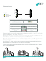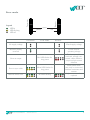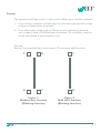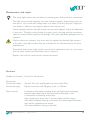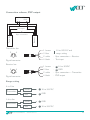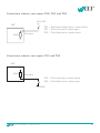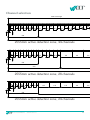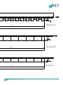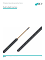
1
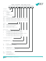
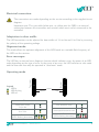
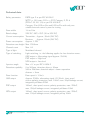
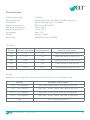
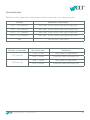
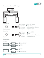
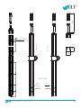
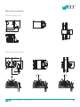
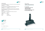
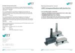
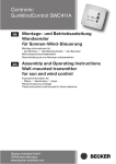
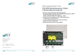
Original operating instructions Sensoric Safety light curtain Sensoric Sensoric GmbH Berlin © www.witt-sensoric.de 1 Order code LIGI - safety light curtain LIGI-01-P01-T00-A-44-2555-F00-C00-S000 Sensoric Description Housing design 01 = standard profile 16x16mm 02 = H profile 29x14mm 11 = separated electronics Output versions OSE = rectangular signal P01 = PNP/positive switching, light-on switching (preferred configuration) P02 = PNP/positive switching, dark-on switching N01 = NPN/negative switching, light-on switching (preferred configuration) N02 = NPN/negative switching, dark-on switching Testing T00 = T01 = T02 = T03 = T04 = without, only activates the alignment mode pull-down resistor, test=low or open pull-down resistor, test=high pull-up resistor, test=low pull-up resistor, test=high or open Beam geometry A = up to 540mm height j 50mm detection capability from 540mm height j 70mm detection capability B = up to 540mm height j 50mm detection capability from 540mm up to 995mm height j 70mm detection capability from 995mm height j 200mm detection capability C = up to 540mm height j 50mm detection capability from 540mm height j 200mm detection capability Active light beams 08...44 Active detection zone in mm (light curtain is longer) F 00 01 = function = with door function (blanking) = without door function (blanking) C 00 = cable length/connector = standard version pig-tail connector with M8 plug, 4-pin S = special version 000 = standard version XXX = custom design without functional difference, for example: color, logo, etc. Sensoric Sensoric GmbH Berlin © www.witt-sensoric.de 2 Sensoric Key to symbols Recommendation for optimal procedure. Risk of death in the case of non-observance. Safety instructions • The safety instructions in the operating manual must be observed. • Installation and electrical connection may only be carried out by trained personnel. • The safety light curtain complies with the requirements of Category 2 and PL=d as per EN 13849-1 and must be integrated into the operating procedure in a faultfree manner in accordance with the applicable regulations and standards in order to achieve proper protective functioning. • In accordance with EN 12978, the safety light curtain is suitable for all door types apart from sluice and dock gates, lift doors, vehicle doors, gates used mainly in animal husbandry, textile theatre curtains, railway level-crossing barriers, barriers that are used solely for vehicle traffic, and dangerous machines that are not doors. • During mounting, installation and commissioning, it must be ensured that the photo switch system cannot be influenced by other photo switch systems or sources of infrared light. • The applicable standards and regulations – particularly EN 12453 (Safety in use of power operated doors) – are to be observed during mounting, installation, commissioning, maintenance and repair. • Strictly observe the regulations of the EN12978 when connecting safety devices on power operated doors. • The manufacturer assumes no liability for damage caused by operation and connection errors, non-observance of the operating manual or lack of maintenance or care; the manufacturer wishes to draw attention again to the possible hazardous situations that can arise in this way. • Notwithstanding conformity with harmonised standards, it is not possible to foresee every potential risk. For this reason, persons should only be present in the hazardous area when necessary. Sensoric Sensoric GmbH Berlin © www.witt-sensoric.de 3 Sensoric Purpose The safety light curtain (LIGI) consists of a transmitter and receiver and is suitable for all automatic door types with a minimum door width of 1.6m. The LIGI complies with the following regulations: EN 12978, EN 12445 and EN 12453. The closing speed of the door is to be selected in such a way that the force limit values as per EN 12453 are adhered to. Only objects that are 5mm larger than the beam separation distance can be detected. Mounting, installation and commissioning Mounting, installation and commissioning of safety light curtains may only be carried out by trained personnel in accordance with the specifications of the door manufacturer. The specifications in this operating manual are also to be adhered to. Operation under conditions other than those intended and modifications to the optics and casing are not permitted and result in loss of EC conformity. When installing PNP/NPN versions, it must be ensured that the door control system checks the safety light curtain versions with a test input once per door cycle. To do so, the control system must trigger the test input on the transmitter for at least 100ms and monitor the reaction behaviour of the output of the receiver. If the time behaviour corresponds to the technical data, the test is successful. Testing by briefly switching off the supply voltage is not suitable. In addition, it must be ensured that the polarity of the supply voltage to the transmitter is in accordance with this manual, depending on the distance between the transmitter and receiver. This setting must also be checked on the transmitter side by means of the green and yellow LEDs. This measure ensures that the transmitter operates with an increased transmission pulse current only for ranges greater than 4m. The safety light curtains are designed in such a way that sunlight and light from halogen lamps and fluorescent tubes (see IEC 61496-2) do not lead to undesired activation. In rare cases, other photo switches or sources of infrared light can lead to undesired activation. These sources of light interference must be dealt with in such cases by switching off, blocking or removing them. Sensoric Sensoric GmbH Berlin © www.witt-sensoric.de 4 Sensoric Mounting, installation and commissioning If two light curtains (in front of and behind the door) are to be used to provide protection, the separation distance between the light curtain and door should be small enough that persons cannot be present undetected between the door and the detection zones that are created. For this application, the two transmitter of the light curtains should be mounted on opposite sides of the door. Only one light curtain can be mounted in the door opening. In this case, the “door function” of the light curtain prevents detection by the door itself. When the light curtain is being mounted, it is to be placed on a stable subsurface. Ensure that the ground is sufficiently level so that the sensor function can work at all points. The first fixing clamp should be around 10cm above the ground and the last clamp should be 10cm from the end; between these points, fixing clamps should be used to fasten the profile at maximum intervals of 60cm. Optical components (transmitters, receivers, LEDs) must not be covered. A risk assessment in accordance with the machinery directive is the basis for deciding on the selected safety method. The alignment of the light curtain should be optimised after it has been mounted. If the test input of the light curtain is activated for longer than 15s, the light curtain switches into alignment mode. The signal reserve can be optimised in alignment mode by alternately rotating the LIGI transmitter and LIGI receiver. If the signal reserve is less than 2, the green receiver LED flashes in this mode. The green LED remains on for signal reserves greater than 2 and the red receiver LED flashes with increasing flash frequency when the signal reserve increases. The signal reserve should be a factor of 2 or greater to ensure fault-free operation as well as to tolerate a certain amount of dirt. As soon as the test input is deactivated for a short period, the light curtain returns to normal mode. Sensoric Sensoric GmbH Berlin © www.witt-sensoric.de 5 Sensoric Electrical connection: The connections are made depending on the version according to the supplied circuit diagram. Important note: The sync cable (white wire, or yellow wire for OSE) is an internal connection between the transmitter and receiver which must not be connected in the controller! Adaptation to door width: The LIGI transmitter can be adjusted for door widths of 1.6 to 4m and 4 to 10m by reversing the polarity of the operating voltage. Alignment mode: This mode allows for optimum alignment of the LIGI based on a variable flash frequency of the LEDs on the receiver. Error messages: The LIGI has an internal error diagnosis function which indicates errors by means of an LED code depending on the type of error. In the event of an error, the LIGI switches to safe mode and the door can then only be operated in "dead man" mode. Legend LED lit LED flashing LED off green yellow Transmitter red Receiver Preset door width 1.6 to 4m Free detection zone Preset door width 4 to 10m Interrupted detection zone Test (LEDs flashing alternately) Sensoric Receiver Transmitter Operating mode Sensoric GmbH Berlin © www.witt-sensoric.de Test (LEDs flashing alternately) 6 Sensoric Legend LED lit LED flashing LED off Receiver Transmitter Alignment mode green yellow red Transmitter Alignment mode (LEDs flashing alternately) Receiver Signal reserve less than 2x Green LED flashing Signal reserve greater than 2x Flash frequency of red LED increases with signal reserve Alignment mode is accessed by activating test or alignment mode for at least 15s and for the duration of alignment. (See pages 12 and 17.) Rotating the transmitter and receiver increases or reduces the reception level. The more the level increases, the faster the flash frequency of the red LED will be. When the maximum flash frequency is reached, the light curtain is optimally aligned and can be fastened in place. For PNP or NPN output versions, the test input must now be disconnected from the fixed potential again and connected to the test input of the controller. The test input is only required for alignment when using the OSE output versions. Connect to 0V in normal operation. 10° 10° Sensoric Sensoric GmbH Berlin © www.witt-sensoric.de 7 Sensoric Legend LED lit LED flashing LED off Receiver Transmitter Error mode green yellow Transmitter red Error mode Receiver No supply voltage Check supply voltage Receiver polarity reversed Check receiver operating voltage Short at output Red LED flashes 2x, long pause Check output cable, overload, wrongly connected, cable defective, output on light curtain defective Error in sync cable Yellow LED flashes 3x, long pause Check white cable, may only be connected between transmitter and receiver Internal device error All LEDs flashing Light curtain must be replaced Sensoric Sensoric GmbH Berlin © www.witt-sensoric.de 8 Sensoric Testing The operation of the light curtain is to be tested as follows once it has been mounted. 1. A test rod with a diameter of 50mm must be continuously detected over a range of 0mm to 500mm above the ground. 2. A test object with an edge length of 200mm must be continuously detected over a range of 0mm to 2500mm above the ground. The test bodies should be moved from bottom to top during these tests. Top view: Door and recommended light curtain layout of T=transmitter and R=receiver T R T R T R Figure 1 Without door function (Blanking function) Sensoric Sensoric GmbH Berlin © www.witt-sensoric.de Figure 2 With door function (Blanking function) 9 Sensoric Maintenance and repair The safety light curtain does not have any wearing parts that need to be maintained. The light entry and exit openings are to be cleaned regularly, depending on the dirt that occurs. Use a cloth with soapy water or a water jet for this purpose. High-pressure cleaners, abrasives and organic solvents must not be used. Check regularly whether the light curtains are correctly aligned. Adjust the alignment if necessary. The light curtain casing, the optics areas, the plug and the connection cable are to be checked regularly for damage. Parts with significant damage must be replaced. If light curtains are replaced, they must only be replaced by identical light curtains or by other safety light curtains that are intended for the relevant door by the door manufacturer. Transmitter and receiver light curtains must only be replaced in pairs so as to ensure that the same software and hardware status is present. Repairs must only be carried out by trained personnel. Versions Number of channels: From 8 to 44 channels Connection: Connection cables Connection plug Door function: Sensoric 5m and 15m, the total length must not exceed 25m Pig-tail connector with M8 plug, 4-pin, L=130mm Continuous interruption starting at the top light beam and going towards lower light beams does not lead to detection as this is interpreted as lowering of the door. After stopping for more than 1.5s interruption will be shown. Only after complete opening of the door an uninterrupted detection zone will be signalled at the output. After that automatic closing is possible. Sensoric GmbH Berlin © www.witt-sensoric.de 10 Sensoric Technical data Safety parameters ESPE type 2 as per IEC 61496-2 MTTFD > 100 years; DCAVG > 99% Category 2; PL d (PFH=7.33.10-9 1/h) as per EN 61508-2; Category 2 for LIGI-xx-Nxx and LIGI-xx-Pxx with only one suitable external control system for testing Door widths 1.6 to 10m Rated voltage 24V DC -58% +25% (10 to 30V DC) Current consumption Transmitter: Approx. 30mA (24V DC) Receiver: Approx. 20mA (24V DC) Power consumption Approx. 1.2W Detection zone height Max. 2555mm Channel count Max. 44 Type of light Modulated infrared Type of switching: Light switching, i.e. the following applies for free detection zones: OSE output = Alternating signal (approx. 950Hz) PNP output = High level NPN output = Low level Aperture angle Max. ±5° as per IEC 61496-2 Detection capability 0 to 500mm, detection object 50mm 500 to 2560mm, detection object beam separation distance + 5mm Door function Door speed 1.3m/s OSE output Approx. 950Hz, alternating signal, 4V 20mA, short proof, reverse polarity protection, max. 100nF, max. 30µA leakage current, integrated pull-down 220 PNP output 100mA, short proof, reverse polarity protection, max. 220nF, max. 350µA leakage current, integrated pull-down 10k NPN output 100mA, short proof, reverse polarity protection, max. 220nF, max. 150µA leakage current, integrated pull-up 10k Sensoric Sensoric GmbH Berlin © www.witt-sensoric.de 11 Sensoric Technical data 100klux Aluminium profile, fully filled, with 2K epoxy resin Pig-tail M8 plug 4-pin, L=130mm IP67 as per EN 60529 -20 to +60°C -30 to +70°C Max. 95% Approx. 1860g 2800x16x16mm (LxWxH) Ambient light safety Housing material Connection Degree of protection Operating temperature Storage temperature Air humidity Weight Dimensions Test input Version Normal operation Test/alignment Internal input wiring T00 <2V >7V 10k pull-down resistor to 0V T01 >7V <2V 10k pull-down resistor to 0V T02 <2V >7V 10k pull-down resistor to 0V T03 >7V <2V 10k pull-up resistor to 24V T04 <2V >7V 10k pull-up resistor to 24V Testing Reaction of the output after activation of the test input for a free detection zone Variant Reaction of the output PNP / 21 channels after max. 50ms switch from high to low level PNP / 22 channels after max. 100ms switch from high to low level NPN / 21 channels after max. 50ms switch from low to high level NPN / 22 channels after max. 100ms switch from low to high level OSE This version is not tested. Sensoric Sensoric GmbH Berlin © www.witt-sensoric.de 12 Sensoric Technical data Reaction of the output after deactivation of the test input for a free detection zone Version Reaction of the output PNP / 21 channels after max. 50ms switch from low to high level PNP / 22 channels after max. 100ms switch from low to high level NPN / 21 channels after max. 50ms switch from high to low level NPN / 22 channels after max. 100ms switch from high to low level OSE This version is not tested. Number of channels 21 channels 22 channels Sensoric Sensoric GmbH Berlin © Switching time Definition t (on) 50ms Interruption of light beam t (off) 400ms Detection zone becoming free t (on) 100ms Interruption of light beam t (off) 800ms Detection zone becoming free www.witt-sensoric.de 13 Sensoric Connection scheme, OSE output Control + – OSE Alignment input Receiver Transmitter yellow Sync connection Transmitter bar 1 brown 2 4 1 3 Pig-tail connector 3 white - 10 to 30V DC and - range setting 2 yellow - Sync connection Receiver 4 green - Alignment input Receiver bar 1 brown - 10 to 30VDC 2 4 3 white - GND 1 3 2 yellow - Sync connection Transmitter 4 green - OSE output 950Hz Pig-tail connector Range setting 4 to 10m brown 10 to 30V DC white GND brown GND white 10 to 30V DC Transmitter 1.6 to 4m Transmitter Sensoric Sensoric GmbH Berlin © www.witt-sensoric.de 14 Sensoric Connection scheme, PNP output Control + – PNP Test input Receiver Transmitter white Sync connection Transmitter bar 2 4 1 3 Pig-tail connector 1 brown - 3 blue - 2 white - Sync connection Receiver 4 black - Test input 10 to 30V DC and range setting Receiver bar 1 brown - 10 to 30VDC 2 4 3 blue - GND 1 3 2 white - Sync connection Transmitter 4 black - PNP output Pig-tail connector Range setting 4 to 10m brown 10 to 30V DC blue GND brown GND blue 10 to 30V DC Transmitter 1.6 to 4m Transmitter Sensoric Sensoric GmbH Berlin © www.witt-sensoric.de 15 Sensoric Connection scheme, NPN output Control + – NPN Test input Receiver Transmitter white Sync connection Transmitter bar 1 brown 2 4 1 3 Pig-tail connector 3 blue - 10 to 30V DC and - range setting 2 white - Sync connection Receiver 4 black - Test input Receiver bar 1 brown - 10 to 30VDC 2 4 3 blue - GND 1 3 2 white - Sync connection Transmitter 4 black - NPN output Pig-tail connector Range setting 4 to 10m brown 10 to 30V DC blue GND brown GND blue 10 to 30V DC Transmitter 1.6 to 4m Transmitter Sensoric Sensoric GmbH Berlin © www.witt-sensoric.de 16 Sensoric Connection scheme, test inputs T00, T01 and T02 10 to 30V LIGI T00 Adjustment=High level or switch closed T01 Test=Low level or switch open T02 Test=High level or switch closed Test input 10k Connection scheme, test inputs T03 and T04 LIGI + 10k Test input T03 Test=Low level or switch closed T04 Test=High level or switch open 0V/GND Sensoric Sensoric GmbH Berlin © www.witt-sensoric.de 17 Sensoric Channel selection 2800 total length 45 45 45 45 45 45 45 45 45 45 45 65 65 65 65 65 65 65 65 65 65 65 65 65 65 22,5 22,5 540 2555mm active detection zone, 44 channels 45 45 45 45 45 45 45 45 45 45 45 65 65 65 65 65 65 195 195 195 195 22,5 22,5 195 540 930 2555mm active detection zone, 28 channels 45 45 45 45 45 45 45 45 45 45 45 195 195 195 22,5 22,5 540 2555mm active detection zone, 24 channels Sensoric Sensoric GmbH Berlin © www.witt-sensoric.de 18 Sensoric 65 65 65 65 65 65 65 65 65 65 65 65 65 65 65 65 65 94 7 Version A 2015 195 195 195 195 65 Version B 1625 195 195 Sensoric GmbH Berlin © 195 65 94 Version C 2015 Sensoric 195 7 195 94 7 195 www.witt-sensoric.de 19 5 130 Sensoric 7 16 Receiver 94 Transmitter indicator LED Anzeige LED 45 16 green green yellow red 22,5 22,5 45 indicator LED Sensoric Sensoric GmbH Berlin © www.witt-sensoric.de 20 Sensoric Mounting materials 17 LIGI-HK 10 fixing clamp 19 16 27 10 LIGI-JK 10 alignment clamp 20 20 21 13 3,5 16 Sensoric Sensoric GmbH Berlin © 10 ° www.witt-sensoric.de 10 ° 21 Sensoric Sensoric Sensoric GmbH Berlin © www.witt-sensoric.de 22 Sensoric Sensoric Witt Sensoric GmbH Gradestraße 48-50 . 12347 Berlin . Germany Tel.: +49 (0) 30 / 75 44 94 - 120 Fax: +49 (0) 30 / 75 44 94 - 123 [email protected] www.witt-sensoric.de Witt Sensoric GmbH V2.0 Sensoric Sensoric GmbH Berlin © www.witt-sensoric.de 24