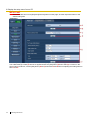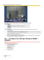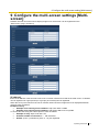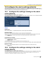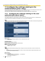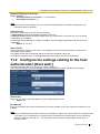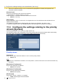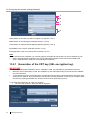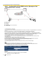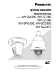
1
Operating Instructions Thermal Camera Model numbers: TC0938450-015CE TC0938450-019CE TC0938450-025CE TC0938450-045CE TC2538450-015CE TC2538450-019CE TC2538450-025CE TC2538450-045CE TC0964070-025CE TC0964070-045CE TC2564070-025CE TC2564070-045CE Before attempting to connect or operate this product, please read these instructions carefully and save this manual for future use. Preface About the user manuals There are 2 sets of operating instructions for the Thermal Camera as follows. • Installation Guide: Explains the physical installation of the Thermal Camera • Operating Instructions: Explains how to perform the settings and how to operate this unit. Trademarks and registered trademarks • Microsoft, Windows, Windows Vista, Internet Explorer, ActiveX and DirectX are either registered • • • • • trademarks or trademarks of Microsoft Corporation in the United States and/or other countries. Microsoft product screen shot(s) reprinted with permission from Microsoft Corporation. iPad, iPhone, and iPod touch are trademarks of Apple Inc., registered in the U.S. and other countries. Android is a trademark of Google Inc. Firefox is a registered trademark of the Mozilla Foundation. All other trademarks identified herein are the property of their respective owners. Abbreviations The following abbreviations are used in these operating instructions. Microsoft® Windows® 7 is described as Windows 7. Microsoft® Windows Vista® is described as Windows Vista. Microsoft® Windows® XP SP3 is described as Windows XP. Windows® Internet Explorer® 9.0, Windows® Internet Explorer® 8.0, Windows® Internet Explorer® 7.0 and Microsoft® Internet Explorer® 6.0 are described as Internet Explorer. Universal Plug and Play is described as UPnP™. Important Information for Thermal Cameras Export Regulation Panasonic Integrated Products may not be used in the design, development, production or use in nuclear, chemical, or biological weapons or missiles. They may not be sold, transferred, or exported to Cuba, Iran, Libya, North Korea, Sudan, or Syria*. Uncooled thermal imaging cameras operating at less than 9 frames per second (9Hz) do not require an export license. Panasonic reserves the right to request an end use statement or end user information for the sale of any Thermal Camera product. * Please visit Panasonic web site for updated details – see link below General Information For Panasonic support please call +44 (0) 870 600 1620 +44 (0) 870 907 0909 WARNING – this is an EN55022:2010 Class A Product. In a domestic environment this product may cause radio interference in which case the user may be required to take adequate measures. 2 Operating Instructions Viewer Software Viewer software It is necessary to install the viewer software “Network Camera View 4S” (ActiveX®) to display images on a PC. This software can be installed directly from the unit or downloaded from the Panasonic website. IMPORTANT • • • • The default setting of “Automatic installation of viewer software” is “On”. Follow the instructions in section 19 when the message is displayed on the information bar of the browser. When the “Live” page is displayed for the first time, the install wizard of the ActiveX control required to display images from the camera will be displayed. Follow the instructions of the wizard. When the install wizard is displayed again even after completing the installation of the ActiveX, restart the PC. The viewer software used on each PC should be licensed individually. The number of installations of the viewer software from the unit can be checked on the [Upgrade] tab of the “Maintenance” page (section 15). Refer to your dealer for the software licensing. Operating Instructions 3 Contents 1 Monitor images on a PC ................................................................................................................ 7 1.1 Monitor images from a single camera ........................................................................................ 7 1.2 About the “Live” page ................................................................................................................. 9 1.3 Monitor images from multiple cameras ..................................................................................... 11 2 Monitor images on a cellular phone/mobile terminal .................................................................... 13 2.1 Monitor images on a cellular phone.......................................................................................... 13 2.2 Monitor images on a mobile terminal........................................................................................ 14 3 Action at an alarm occurrence ..................................................................................................... 17 3.1 Alarm type................................................................................................................................ 17 3.2 Action at an alarm occurrence.................................................................................................. 17 4 Transmit images onto an FTP server ........................................................................................... 18 4.1 Transmit an alarm image at an alarm occurrence (Alarm image transmission) ........................ 18 4.2 Transmit images at a designated interval or period (FTP periodic image transmission) ........... 18 5 About the network security .......................................................................................................... 19 5.1 6 Equipped security functions ..................................................................................................... 19 Display the setup menu from a PC .............................................................................................. 20 6.1 How to display the setup menu ................................................................................................ 20 6.2 How to operate the setup menu ............................................................................................... 21 6.3 About the setup menu window ................................................................................................. 23 7 Configure the basic settings of the unit [Basic] ............................................................................ 25 7.1 Configure the basic settings [Basic] ......................................................................................... 25 7.2 Configure the Internet settings [Internet] .................................................................................. 27 8 Configure the settings relating to images [Image] ........................................................................ 30 8.1 Configure the settings relating to the Picture (Camera) mode/Video input [JPEG/H.264] ........ 30 8.2 Configure the settings relating to JPEG images [JPEG/H.264] ................................................. 30 8.3 Configure the settings relating to H.264 images [JPEG/H.264] ................................................ 31 8.4 Configure the settings relating to image and positions [Image/Position] ................................... 35 8.5 Configure the settings relating to RS485 [RS485] .................................................................... 36 9 Configure the multi-screen settings [Multi-screen] ....................................................................... 37 10 Configure the alarm settings [Alarm] ............................................................................................. 39 10.1 Configure the settings relating to the alarm action [Alarm] ....................................................... 39 10.2 Configure the settings relating to the alarm image [Alarm] ....................................................... 39 10.3 Configure the VMD settings [VMD area] .................................................................................. 41 10.3.1 Set the VMD areas [VMD area] ......................................................................................... 43 10.4 Configuration of the settings relating to the E-mail notification [Notification] ............................. 45 10.5 Configure the settings relating to Panasonic alarm protocol [Notification] ................................ 46 11 Configure the settings relating to the authentication [User mng.] .................................................. 48 11.1 4 Configure the settings relating to the user authentication [User auth.] ...................................... 48 Operating Instructions 11.2 Configure the settings relating to the host authentication [Host auth.] ...................................... 49 11.3 Configure the settings relating to the priority stream [System] .................................................. 50 12 Configure the settings of the servers [Server] ............................................................................... 52 12.1 Configure the settings relating to the E-mail server [E-mail] ..................................................... 52 12.2 Configure the settings relating to the FTP server [FTP] ............................................................ 53 12.3 Configure the settings relating to the NTP server [NTP] ........................................................... 54 13 Configuring the network settings [Network] ................................................................................... 56 13.1 Configure the network settings [Network] ................................................................................. 56 13.2 Configure the HTTPS settings.................................................................................................. 63 13.2.1 Generation of the CRT key (SSL encryption key) .............................................................. 64 13.2.2 Generation of the self-signed certificate (security certificate) ............................................ 65 13.2.3 Generation of CSR (Certificate Signing Request).............................................................. 67 13.2.4 Installation of the server certificate .................................................................................... 68 13.2.5 Configuration of the connection protocol ........................................................................... 69 13.3 Access the unit using the HTTPS protocol ............................................................................... 70 13.3.1 13.4 Install the security certificate ............................................................................................. 70 Configure the settings relating to DDNS [DDNS] ...................................................................... 79 13.4.1 Configuration of the DDNS service (Example of the “Viewnetcam.com” service) .............. 80 13.4.2 When using the “Viewnetcam.com” service....................................................................... 81 13.4.3 Procedure to register information for the “Viewnetcam.com” service ................................. 81 13.4.4 Checking the information registered for the “Viewnetcam.com” service ............................ 84 13.4.5 When using “Dynamic DNS Update” ................................................................................. 84 13.4.6 When using “Dynamic DNS Update(DHCP)” ..................................................................... 84 13.5 Configure the settings relating to SNMP [SNMP] ..................................................................... 84 13.6 Configure the settings relating to the FTP periodic image transmission [FTP img. trans.] ........ 85 13.7 Configure the schedule settings of the FTP periodic image transmission [FTP img. trans.] ...... 87 13.7.1 How to set the schedules .................................................................................................. 87 13.7.2 How to delete the set schedule ......................................................................................... 88 14 Configure the settings relating to the schedules [Schedule] .......................................................... 90 15 Maintenance of the unit [Maintenance] ......................................................................................... 92 15.1 Check the system log [System log] .......................................................................................... 92 15.2 Upgrade the firmware [Upgrade] .............................................................................................. 92 15.3 Check the status [Status] ......................................................................................................... 94 15.4 Reset the settings/Reboot the unit [Default reset] .................................................................... 95 16 Number of users that can concurrently access the unit ................................................................. 96 17 Using the IP Setting Software ....................................................................................................... 97 18 About the displayed system log .................................................................................................... 99 19 Troubleshooting .......................................................................................................................... 102 Operating Instructions 5 Appendix A – Introduction to Thermal Imaging ................................................................................ 108 A.1 Light Basics ................................................................................................................................ 108 A.2 Uncooled infrared detectors ....................................................................................................... 108 A.3 Atmospheric conditions and their effect of Thermal Imaging. ...................................................... 109 A.3.1 Humidity;.............................................................................................................................. 109 A.3.2 Fog, rain & snow: ................................................................................................................. 109 A.4 Examples of Thermal Images ..................................................................................................... 109 Appendix B – Hyperfocal Distance .................................................................................................. 111 B.1 Hyperfocal Distance Table. ........................................................................................................ 111 6 Operating Instructions 1 Monitor Images on a PC 1 Monitor images on a PC The following are descriptions of how to monitor images from the camera on a PC. 1.1 Monitor images from a single camera 1. Start up the web browser. 2. Enter the IP address designated using the Panasonic “IP Setting Software” in the address box of the browser. Example when entering an IPv4 address: http://URL registered using IPv4 address http://192.168.0.10/ Example when entering an IPv6 address: http://[URL registered using IPv6 address] http://[2001:db8::10]/ <Example of IPv4 access> <Example of IPv6 access> IMPORTANT When the HTTP port number is changed from “80”, enter “http://IP address of the unit + : (colon)+ port number” in the address box of the browser. (Example: http://192.168.0.11:8080) When the PC is in a local network, configure the proxy server setting of the web browser (under [Internet Options...] under [Tools] of the menu bar) to bypass the proxy server for the local address. Note Refer to section 13.3 for further information about the case in which “HTTPS” is selected for “HTTPS” “Connection” on the [Network] tab of the “Network” page (section 13). 3. Press the [Enter] key on the keyboard. The “Live” page will be displayed. Refer to section 1.2 for further information about the “Live” page. Operating Instructions 7 1 Monitor Images on a PC When “On” is selected for “User auth.”, the authentication window will be displayed before displaying live images for the user name and password entries. The default user name and password are as follows: User name: admin Password: 12345 IMPORTANT • • To enhance the security, change the password for the user name “admin”. It is recommended to change this password periodically. When displaying multiple H.264 images on a PC, images may not be displayed depending on the performance of the PC. Note • The maximum number of concurrent access user is 14 including users who is receiving H.264 images and users who are receiving JPEG images. Depending on the set values for “Bandwidth control(bit rate)” and “Max bit rate (per client)”, the maximum concurrent access number may be 14 or less users. When 14 users are concurrently accessing, the access limit message will be displayed for users who subsequently attempt to access. When “Multicast” is selected for “Transmission type” of “H.264”, only the first user who accessed to monitor H.264 images will be included in the maximum number. The second and subsequent users who are monitoring H.264 images will not be included in the maximum number. • When “On” is selected for “H.264 transmission” (section 8.3), H.264 images will be displayed. When “Off” is selected, a JPEG image will be displayed. It is possible to display a JPEG image even when “On” is selected for “H.264 transmission”. In this case, the refresh interval of JPEG images will be limited. • The refresh interval may become longer depending on a network environment, PC performance, photographic subject, access traffic, etc. <Refresh interval of JPEG images> When “On” is selected for “H.264 transmission” Max. 4.2 fps When “Off” is selected for “H.264 transmission” Max. 25 fps 8 Operating Instructions 1 Monitor Images on a PC 1.2 About the “Live” page A [select language] pull-down-menu The unit’s display language can be selected. The default language can be set in the [Language] in the [Basic] settings. (section 7) B [Setup] button*1 Displays the setup menu. The button will turn green and the setup menu will be displayed. C [Live] button Displays the “Live” page. The button will turn green and the “Live” page will be displayed. D [Multi-screen] buttons Images from multiple cameras can be displayed on a multi-screen by registering units/network cameras on the setup menu. (section 1.3) E [Compression] buttons • [H.264] button: The characters “H.264” on the button will turn green and an H.264 image will be displayed. When “On” is selected for “H.264 transmission” of “H.264(1)”, “H.264(2)”, the [H.264] button will be displayed. (section 8.3) • [JPEG] button: The characters “JPEG” on the button will turn green and a JPEG image will be displayed. F [Stream] buttons These buttons will be displayed only when an H.264 image is displayed. • [1] button: The character “1” will turn green and images in the main area will be displayed in accordance with the setting of “H.264(1)”. (section 8.3) • [2] button: The character “2” will turn green and images in the main area will be displayed in accordance with the setting of “H.264(2)”. (section 8.3) Operating Instructions 9 1 Monitor Images on a PC G [Image capture size] buttons These buttons will be displayed only when a JPEG image is displayed. [VGA] The characters “VGA” will turn green and images in the main area will be displayed in VGA size. [QVGA] The characters “QVGA” will turn green and images in the main area will be displayed in QVGA size. [D1] This option is not supported by the Thermal Camera H [Image quality] buttons These buttons will be displayed only when a JPEG image is displayed. [1] button: Images in the main area will be displayed in accordance with the setting for “Quality1” of “Image quality setting”. (section 8.2) [2] button: Images in the main area will be displayed in accordance with the setting for “Quality2” of “Image quality setting”. (section 8.2) I [Zoom] buttons*2 : Click this button to adjust the zoom ratio to the “Wide” side. : Click this button to set the zoom ratio to x1.0. : Click this button to adjust the zoom ratio to the “Tele” side. J [Focus] buttons This feature is not supported on the Thermal Camera K [Auto mode] This feature is not supported on the Thermal Camera L Control pad/buttons*2 Left-click on the control pad or buttons to adjust the horizontal/vertical position of the camera (panning/ tilting). Panning/tilting speed will be faster if a clicked point gets farther from the center point of the control pad. It is also possible to pan/tilt the camera by dragging the mouse. Zoom and focus can be adjusted by right-clicking. When an upper/lower area of the control pad is rightclicked, the displayed image will be zoomed in/out on. When a left/right area is right-clicked, the focus will be adjusted to the Near/Far side. Zoom can also be adjusted using the mouse wheel. Note that the Thermal Camera does not support optical zoom or physical pan/tilt – the Pan/Tilt/Zoom controls are digital only, within an existing image. M [Brightness] buttons Left click on the “+” and “–” buttons to cycle through the different display options available: Greyscale (White hot) Greyscale (Black hot) Ironbow Left-click on the “Normal” button to return to the default value: Greyscale (White hot) N [Preset] This feature is not supported on the Thermal Camera O Unit title The title entered for “Unit title” on the [Basic] tab will be displayed. (section 7.1) 10 Operating Instructions 1 Monitor Images on a PC P Alarm occurrence indication button*2 This button will be displayed and will blink when an alarm has occurred. When this button is clicked, this button will disappear. (section 3) Q Full screen button Images will be displayed on a full screen. To return to the “Live” page, press the [Esc] key. The aspect ratio of displayed images will be adjusted in accordance with the monitor. R Snap shot button Click this button to take a picture (a still picture). The picture will be displayed on a newly opened window. When right-clicking on the displayed image, the pop-up menu will be displayed. It is possible to save the image on the PC by selecting “Save” from the displayed pop-up menu. When “Print” is selected, printer output is enabled. Note For the case of using Windows 7 or Windows Vista, the following settings may be required. Open Internet Explorer, click [Tools] [Internet Options] [Security] [Trusted Sites] [Sites]. Register the unit address on [Website] of the displayed trusted widows. S Main area Images from the camera will be displayed in this area. The current time and date will be displayed according to the settings configured for “Time display format” and “Date/time display format”. (section 7.1) When clicking a desired point while displaying live images in the main area, the camera will move to locate the clicked point at the center of the main area. Note When operated by a lower access level user, images displayed on the screen may be changed temporarily. This does not affect operation of the unit. Depending on the PC in use, screen tearing* may occur when the shooting scene drastically changes due to the GDI restrictions of the OS. *A phenomenon in which portions of the screen are displayed out of alignment. *1 Only *2 operable by users whose access level is “1. Administrator”. Only operable by users whose access level is “1. Administrator” or “2. Camera control” when “On” is selected for “User auth.” (section 11) 1.3 Monitor images from multiple cameras Images from multiple cameras can be displayed on a multi-screen. Images from 4 cameras (up to 16 cameras) can be displayed simultaneously. In order to use multi-screen, IP addresses of network cameras and units used to connect to cameras must be configured to the unit. 4 cameras can be registered as a group and up to 4 groups (16 cameras) can be registered. (section 9) IMPORTANT When displaying images on a 16-screen, panning, tilting and zooming operations become unavailable for images from cameras with Pan/Tilt/Zoom functions. When the power is turned off or the LAN cable is disconnected while displaying images, displaying images on a multi-screen from the “Live” page will become unavailable. Note When displaying images on a 4-screen, panning, tilting and zooming operations become available only for images from cameras with Pan/Tilt/Zoom functions. Refer to our website (http://panasonic.net/pss/security/support/info.html) for further information about the compatible cameras and their versions. Only JPEG images can be displayed on a multi-screen. Operating Instructions 11 1 Monitor Images on a PC “Network Camera Recorder with Viewer Software Lite” which supports live monitoring and recording images from multiple cameras is available. For further information, refer to our website (http://panasonic.net/pss/security/support/info.html). 1. Click the desired [Multi-screen] button. Images from the registered cameras will be displayed on a selected multi-screen (screen can be split up to 16 areas). The following are instructions when displaying on a 4-split screen. A To show 1 camera screen, click the [Live] button. You can also click “1” below “Multi-screen” to display the live image from the camera. B Click the [Multi-screen] button to display images from cameras in a multi-screen of 4 to 16 screens. C Click a camera title. Live images from the camera corresponding to the clicked camera title will be displayed on the “Live” page of the newly opened window. 12 Operating Instructions 2 Monitor images on a cellular phone/mobile terminal 2 Monitor images on a cellular phone/mobile terminal 2.1 Monitor images on a cellular phone It is possible to connect to the unit using a cellular phone via the Internet and monitor images (JPEG only) from the unit on the screen of the cellular phone. It is also possible to refresh images to display the latest image. IMPORTANT When the authentication window is displayed, enter the user name and password. The default user name and password are as follows. User name: admin Password: 12345 To enhance the security, change the password for the user “admin”. (section 11) If the cellular phone in use is not compatible with UTF-8 encode, it is impossible to display the screen correctly. Note It is necessary to configure the network settings of the cellular phone in advance to connect to the Internet and monitor images from the unit. (section 13) 1. Access to “http://IP address/mobile”*1 or “http://Host name registered in the DDNS server/mobile” using a cellular phone. Images from the unit will be displayed. A Manual Refresh/Auto Refresh Press the dial key “5” or the [Manual Refresh] button to refresh the camera images. Press the [Auto Refresh] button to refresh the images from the camera in 5-second intervals. When the dial key “5” or the [Manual Refresh] button is pressed again, the refresh mode of the camera will return to manual refresh. Operating Instructions 13 2 Monitor images on a cellular phone/mobile terminal IMPORTANT Transmission will be periodically performed when “Auto Refresh” is selected for the camera image. Confirm the contract plan of the cellular phone in use before using this function. Depending on the cellular phone in use, “Auto Refresh” may be unavailable. B Resolution control Changes the image capture size by pressing the dial key “0”. Picture (Camera) mode VGA [4:3] 320x240 (default)/640x480 Picture (Camera) mode VGA [16:9] Not supported by the Thermal Camera C Image quality control It is possible to change the image quality between “Quality1” and “Quality2”. (section 8.2) Note The pan/tilt/zoom/focus functions of cameras connected to the unit cannot be operated from cellular phones. Some cellular phones cannot change the image capture size even when resolution is changed by resolution control. When the HTTP port number is changed from “80”, enter “http://IP address: (colon) + port number/ mobile”*1 in the address box of the browser. When using the DDNS function, access to “http://Host name registered in the DDNS server: (colon) + port number/mobile”. When the authentication window is displayed, enter the user name of an administrator or user and password. Depending on the cellular phone in use, password entry may be required each time the screen is switched. Depending on the cellular phone in use, larger size images may not be displayed. In this case, selecting “9 Low” for “Image quality setting” of “JPEG” (section 8.2) may sometimes solve this problem. Depending on the cellular phone in use or its contract plan, it may be impossible to access. When “HTTPS” is selected for “HTTPS” - “Connection” on the [Network] tab of the “Network” page, enter as follows. “https://IP address: (colon) + port number/mobile” or “https://Host name registered in the DDNS server: (colon) + port number/mobile” *1 IP address is the global WAN IP address of the router that can be accessed via the Internet. 2.2 Monitor images on a mobile terminal It is possible to connect to the unit using a mobile terminal via the Internet and monitor images (MJPEG only) from the unit on the screen of the mobile terminal. Images are refreshed automatically to display the latest image. The compatible mobile terminals are shown as follows. (As of December, 2012) iPad, iPhone, iPod touch (iOS 4.2.1 or later) Android™ mobile terminals When an Android terminal is used, an MJPEG format image is displayed by the Firefox® browser, but a JPEG format image is displayed by the standard browser. For further information about compatible devices, refer to our website (http://panasonic.net/pss/security/support/info.html). IMPORTANT When the authentication window is displayed, enter the user name and password. The default user name and password are as follows. User name: admin Password: 12345 To enhance the security, change the password for the user “admin”. (section 11) 14 Operating Instructions 2 Monitor images on a cellular phone/mobile terminal Note It is necessary to configure the network settings of the mobile terminal in advance to connect to the Internet and monitor images from the unit. (section 13) 1. Access to “http://IP address/cam”*1 or “http://Host name registered in the DDNS server/cam”*2 using a mobile terminal. Images from the unit will be displayed. A Live images area Displays images from the camera. B Resolution control The resolution can be changed by selecting a resolution setting from the buttons. Picture (Camera) mode VGA [4:3] 320x240/640x480 (default) Picture (Camera) mode VGA [16:9] Not supported by the Thermal Camera Note You can change the image size displayed on the mobile terminal by accessing the following addresses. Large display: http://IP address/cam/dl Medium display: http://IP address/cam/dm Small display: http://IP address/cam/ds The pan/tilt/zoom/focus functions of cameras connected to the unit cannot be operated from mobile terminals. When the resolution is changed by the resolution control, the displayed resolution changes but the image size remains the same. When the HTTP port number is changed from “80”, enter “http://IP address: (colon) + port number/ cam” *1 in the address box of the browser. When using the DDNS function, access to “http://Host name registered in the DDNS server: (colon) + port number/cam”*2. When “HTTPS” is set in “HTTPS” - “Connection” on the [Network] tab of the “Network” page, enter the following: “https://IP address: (colon) + port number/cam” or “https://Host name registered in the DDNS server: (colon) + port number/cam”. When the authentication window is displayed, enter the user name of an administrator or user and password. Depending on the mobile terminal in use, password entry may be required each time the screen is switched. Operating Instructions 15 2 Monitor images on a cellular phone/mobile terminal Depending on the mobile terminal in use, larger size images may not be displayed. In this case, selecting “9 Low” for “Image quality setting” of “JPEG” (section 8.2) may sometimes solve this problem. Depending on the mobile terminal in use or its contract plan, it may be impossible to access. *1 *2 16 IP address is the global WAN IP address of the router that can be accessed via the Internet. However, when accessing the same LAN as the unit with a wireless compatible mobile terminal, the IP address is the local IP address. Only when accessing the unit through the Internet. Operating Instructions 3 Action at an alarm occurrence 3 Action at an alarm occurrence The alarm action (action at an alarm occurrence) will be performed when the following alarms occur. 3.1 Alarm type VMD alarm: When motion is detected in the set VMD area, the alarm action will be performed. *VMD stands for “Video Motion Detection”. Command alarm: When a Panasonic alarm protocol is received from the connected device via a network, the alarm action will be performed. Video loss alarm: The alarm will be activated when there is a loss of video input signals due to disconnection of the thermal detector inside the Thermal Camera or camera problems. 3.2 Action at an alarm occurrence Display the alarm occurrence indication button on the “Live” page The alarm occurrence indication button will be displayed on the “Live” page at an alarm occurrence. (section 1.2) IMPORTANT When “Polling(30s)” is selected for “Alarm status update mode” (section 7.1), the Alarm occurrence indication button will be refreshed in 30-second intervals. For this reason, it may take a maximum of30 seconds until the alarm occurrence indication button is displayed on the “Live” page at an alarm occurrence. Transmit an image onto a server automatically An alarm image can be transmitted at an alarm occurrence to the server designated in advance. The settings required to transmit an alarm image to a server can be configured in the “Alarm image” section on the [Alarm] tab of the “Alarm” page (section 10.2) and the [FTP] tab of the “Server” page (section 12.2). Notify of alarm occurrences by E-mail Alarm E-mail (alarm occurrence notification) can be sent at an alarm occurrence to the E-mail addresses registered in advance. Up to 4 addresses can be registered as recipients of the alarm E-mail. The settings for alarm E-mail can be configured in the “E-mail notification” section on the [Notification] tab of the [Alarm] page (section 10.4) and the [E-mail] tab of the “Server” page (section 12). Notify of alarm occurrences to the designated IP addresses (Panasonic alarm protocol notification) This function is available only when a Panasonic device, such as the network disk recorder, is connected to the system. When “On” is selected for “Panasonic alarm protocol notification”, the connected Panasonic device will be notified that the unit is in the alarm state. The settings for Panasonic alarm protocol can be configured in the Panasonic alarm protocol section of the [Notification] tab of the [Alarm] page. (section 10.5) Operating Instructions 17 4 Transmit images on to an FTP server 4 Transmit images onto an FTP server Images can be transmitted to an FTP server. By configuring the following settings, transmission of images captured at an alarm occurrence or captured at a designated interval to an FTP server will become available. IMPORTANT When using this function, set the user name and the password to access the FTP server to restrict users who can log into the FTP server. 4.1 Transmit an alarm image at an alarm occurrence (Alarm image transmission) An alarm image can be transmitted at an alarm occurrence to the FTP server. To transmit alarm images to an FTP server, it is necessary to configure the settings in advance. The settings for the FTP server can be configured on the [FTP] tab of the “Server” page. (section 12.2) The alarm image transmission function can be turned on/off in the “Alarm image” section of the [Alarm] tab of the “Alarm” page. (section 10.2) Note Depending on the line speed or the traffic, the number of the transmitted images may not reach the set number of images to be transmitted. 4.2 Transmit images at a designated interval or period (FTP periodic image transmission) Images can be transmitted at a designated interval or period. To transmit images at a designated interval or period, it is necessary to configure the settings in advance. The settings for the FTP server can be configured on the [FTP] tab of the “Server” page. (section 12.2) It is possible to determine whether or not to use the FTP periodic image transmission function and to configure the settings relating to alarm images and the schedule on the “FTP img. trans.” tab of the “Network” page. (section 13.6) Note Depending on the line speed or the traffic, images may not be transmitted at the designated interval. When “On” is selected for both the alarm image transmission function and the FTP periodic image transmission function, the alarm image transmission function will be given priority over the FTP periodic image transmission function. Therefore, images may not be transmitted at the interval designated on the “FTP periodic image transmission” setting. 18 Operating Instructions 5 About the network security 5 About the network security 5.1 Equipped security functions The following security functions are featured in this unit. Access restrictions by the host authentication and the user authentication It is possible to restrict users from accessing the unit by setting the host authentication and/or the user authentication to “On”. (section 11) Access restrictions by changing the HTTP port It is possible to prevent illegal access such as port scanning, etc. by changing the HTTP port number. (section 13.1) Access encryption by the HTTPS function It is possible to enhance the network security by encrypting the access to units using the HTTPS function. (section 13.2) IMPORTANT Design and enhance security countermeasures to prevent leakage of information such as image data, authentication information (user name and password), alarm E-mail information, FTP server information, DDNS server information, etc. Perform the countermeasure such as access restriction (using the user authentication) or access encryption (using the HTTPS function). After the unit is accessed by the administrator, make sure to close all the browsers for added security. Change the administrator password periodically for added security. Note When user authentication (authentication error) has failed to pass 8 times within 30 seconds using the same IP address (PC), access to the unit will be denied for a while. Operating Instructions 19 6 Display the setup menu from a PC 6 Display the setup menu from a PC The settings of the unit can be configured on the setup menu. IMPORTANT The setup menu is only operable by users whose access level is “1. Administrator”. Refer to section 11 for how to configure the access level. 6.1 How to display the setup menu 1. Display the “Live” page. (section 1) 2. Click the [Setup] button on the “Live” page. The window with the user name and password entry fields will be displayed. 3. Click the [OK] button after entering the user name and the password. 20 The default user name and password are as follows. User name: admin Password: 12345 → The setup menu will be displayed. Refer to section 6.3 for further information about this menu. Operating Instructions 6 Display the setup menu from a PC 6.2 How to operate the setup menu A Menu buttons B Setup page 1. Click the desired button in the frame on the left of the window to display the respective setup menu. When there are tabs at the top of the “Setup” page displayed in the frame on the right of the window, click the desired tab to display and configure the setting items relating to the name of the tab. 2. Complete each setting item displayed in the frame on the right of the window. 3. After completing each setting item, click the [Set] button to apply them. Operating Instructions 21 6 Display the setup menu from a PC IMPORTANT When there are two or more [Set] and [Execute] buttons on the page, click the respective button to the edited setting item <Example> When completing the setting items in field A, click the [Set] button (B) below field (A). The edited settings in field (A) will not be applied unless the [Set] button (B) below field (A) is clicked. In the same manner as above, click the [Set] button (D and F) below field C and E when completing the setting items in field C and E. 22 Operating Instructions 6 Display the setup menu from a PC 6.3 About the setup menu window L A B C D E F M G H I J K A [Setup] button Displays the “Setup” page. B [Live] button Displays the “Live” page. C [Basic] button Displays the “Basic” page. The basic settings such as time and date and the unit title, and the settings required to connect the unit to the Internet can be configured on the “Basic” page. (section 7.1) D [Image] button Displays the “Image” page. The settings relating to image quality, image capture size, etc. of JPEG/H.264 camera images can be configured on the “Image” page. (section 8.1) E [Multi-screen] button Displays the “Multi-screen” page. The cameras from which images are to be displayed on a multi-screen can be registered on the “Multi-screen” page. (section 9) F [Alarm] button Displays the “Alarm” page. The settings relating to alarm occurrences such as settings for the alarm action at an alarm occurrence, the alarm occurrence notification, and the VMD area settings can be configured on the “Alarm” page. (section 10) G [User mng.] button Displays the “User mng.” page. The settings relating to the authentication such as users and PCs restrictions for accessing the unit can be configured on the “User mng.” page. (section 11) Operating Instructions 23 6 Display the setup menu from a PC H [Server] button Displays the “Server” page. The settings relating to the E-mail server, the FTP server and the NTP server to which the unit accesses can be configured on the “Server” page. (section 12) I [Network] button Displays the “Network” page. The network settings and the settings relating to DDNS (Dynamic DNS), SNMP (Simple Network Management Protocol) and the FTP (File Transfer Protocol) periodic transmission can be configured on the “Network” page. (section 13) J [Schedule] button Displays the “Schedule” page. On the “Schedule” page, it is possible to designate time zones to allow to activate the VMD detection function. (section 14) K [Maintenance] button Displays the “Maintenance” page. System log check, firmware upgrade, status check and initialization of the setup menu can be carried out on the “Maintenance” page. (section 15) L Unit title The title of the unit whose settings are currently being configured will be displayed. M Setup page Pages of each setup menu will be displayed. There are tabs for some setup menus. 24 Operating Instructions 7 Configure the basic settings of the unit [Basic] 7 Configure the basic settings of the unit [Basic] The settings relating to configuring the unit title, time and date, and connecting to the Internet can be configured on the “Basic” page. The “Basic” page has 2 tabs; the [Basic] tab and the [Internet] tab. 7.1 Configure the basic settings [Basic] Click the [Basic] tab of the “Basic” page. (section 6) The settings such as the unit title, time and date, etc. can be configured on this page. [Unit title] Enter the title of the unit. Click the [Set] button after entering the title of the unit. The entered title will be displayed in the unit title field. Available number of characters: 0 - 20 characters Unavailable characters: " & Default: WJ-GXE100 [Date/time] Enter the current time and date. When “12h” is selected for “Time display format”, “AM” or “PM” can be selected. Available range: Jan/01/2010 00:00:00 - Dec/31/2035 23:59:59 IMPORTANT Use an NTP server when the more accurate time & date setting is required for the system operation. (section 12.3) Operating Instructions 25 7 Configure the basic settings of the unit [Basic] [Time display format] Select the time display format from “24h”, “12h” and “Off”. Enter the current hour reflecting this setting when entering the current time and date for “Date/time”. To hide time and date, select “Off”. Default: 24h [Date/time display format] Select a date/time display format. When “2010/04/01 13:10:00” is set for “Date/time” after selecting “24h” for “Date/time display format”, time & date will be respectively displayed as follows. DD/MM/YYYY: 01/04/2010 13:10:00 MM/DD/YYYY: 04/01/2010 13:10:00 DD/Mmm/YYYY: 01/Apr/2010 13:10:00 YYYY/MM/DD: 2010/04/01 13:10:00 Mmm/DD/YYYY: Apr/01/2010 13:10:00 Default: DD/MM/YYYY [Summer time (daylight saving)] Select “In”, “Out” or “Auto” to determine whether or not to apply daylight saving time. Configure this setting if the summer time (daylight saving time) is applied in the location where the unit is in use. In: Applies summer time. An asterisk (*) will be displayed on the left side of the displayed time and date. Out: Does not apply summer time. Auto: Applies summer time in accordance with the settings for “Start time & date” and “End time & date” (month, week, day of the week, time). Default: Out [NTP/Time zone] When “NTP >>” is clicked, the [NTP] tab of the “Server” page will be displayed. (section 12.3) [Start time & date] [End time & date] When “Auto” is selected for “Summer time (daylight saving)”, select the time & date for the start time and the date time (month, week, day of the week, time). [Camera title on screen] Select “On” or “Off” to determine whether or not to display the camera title on the screen. When “On” is selected, the character string entered for “Camera title on screen (0-9, A-Z)” will be displayed at the position selected for “OSD”. Default: Off [Camera title on screen (0-9, A-Z)] Enter a character string to be displayed on the image. Available number of characters: 0 - 20 characters Available characters: 0-9, A-Z and the following marks. !"#$%&'()*+,-./:;=? Default: None (blank) [OSD] - [Position] Select the position where the time and date and a character string to be displayed on the image of the “Live” page. Upper left: The above information will be displayed at the upper left corner of the main area on the “Live” page. Lower left: The above information will be displayed at the lower left corner of the main area on the “Live” page. Upper right: The above information will be displayed at the upper right corner of the main area on the “Live” page. Lower right: The above information will be displayed at the lower right corner of the main area on the “Live” page. Default: Upper left 26 Operating Instructions 7 Configure the basic settings of the unit [Basic] [Indicator] This feature is not supported on the Thermal Camera. This setting will have no visible effect. [Alarm status update mode] Select an interval of the unit status notification from the following. When the status of the unit changes, the alarm occurrence indication button will be displayed to notify of the unit status. Polling(30s): Updates the status each 30 seconds and provide notification of the unit status. Real time: Provide notification of the unit status when the status has changed. Default: Real time Note Depending on the network environment, notification may not be provided in real time. When multiple cameras are using the same “Alarm status reception port”, even if “Real time” is selected for “Alarm status update mode”, status notification is not provided in real time. In this case, change the “Alarm status reception port” settings. [Alarm status reception port] When selecting “Real time” for “Alarm status update mode”, designate a port number to which the status change notification is to be sent. Available port number: 1 - 65535 Default: 31004 The following port numbers are unavailable since they are already in use. 20, 21, 23, 25, 42, 53, 67, 68, 69, 80, 110, 123, 161, 162, 443, 995, 10669, 10670 [Automatic installation of viewer software] Determine whether or not to install the viewer software from this unit. On: Installs the viewer software from the unit automatically. Off: The viewer software cannot be installed from the unit. Default: On IMPORTANT It is impossible to display images between the camera and the PC when the viewer software “Network Camera View 4S” is not installed on the PC. The number of the viewer software installations can be checked on the [Upgrade] tab of the “Maintenance” page. [Language] Select the language to initially display when the unit is accessed from the following. English/Japanese/Italian/French/German/Spanish/Chinese/Russian Default: English The language displayed on the “Live” page can also be changed. (section 1.2) 7.2 Configure the Internet settings [Internet] Click the [Internet] tab of the “Basic” page. (section 6) The settings relating to UPnP (Auto port forwarding), DDNS (Viewnetcam.com), and network settings for the Internet can be configured on this page. Operating Instructions 27 7 Configure the basic settings of the unit [Basic] [UPnP (Auto port forwarding)] Select “On” or “Off” to determine whether or not to use the port forwarding function of the router. To use the auto port forwarding function, the router in use must support UPnP and the UPnP must be enabled. Default: Off Note Due to auto port forwarding, the port number may sometimes be changed. When the number is changed, it is necessary to change the port numbers registered in the PC and recorders, etc. The UPnP function is available when the unit is connected to the IPv4 network. IPv6 is not supported. To check if auto port forwarding is properly configured, click the [Status] tab on the “Maintenance” page, and check that the “Enable” is displayed for “Status” of “UPnP”. (section 15.3) When “Enable” is not displayed, refer to “Cannot access the unit via the Internet.” in20 Troubleshooting. When the “UPnP (Auto port forwarding)” setting is changed, the “Auto port forwarding” setting under“UPnP” on the [Network] tab of the “Network” page also changes to the same setting. [DDNS] Select “Viewnetcam.com” or “Off” to determine whether or not to use “Viewnetcam.com”. By selecting “Viewnetcam.com” and clicking the [Set] button, the registration window for “Viewnetcam.com” will be displayed in a newly opened window. Follow the on-screen instructions to register with “Viewnetcam.com”. Refer to section 13.4.3 or the “Viewnetcam.com” website (http://www.viewnetcam.com/) for further information. Default: Off Note When the “DDNS” setting is changed, the “DDNS” setting on the [DDNS] tab of the “Network” page also changes to the same setting. [Recommended network setting for internet] The recommended settings for connecting to the Internet are performed here. By clicking the [Set] button, a dialog displaying how the following settings will change is displayed. Click the [OK] button after checking the settings to change the settings to the displayed values. [JPEG/H.264] tab on the “Image” page – [H.264(1)]/[H.264(2)] – [Internet mode (over HTTP)]: On – [Transmission priority]: Best effort – [Max bit rate (per client)*]: Max. 1024 kbps, Min. 128 kbps – [H.264(1)] – [Image capture size]: VGA – [H.264(2)] – [Image capture size]: QVGA [Network] tab on the “Network” page – [Common] – [Max RTP packet size]: Limited(1280byte) 28 Operating Instructions 7 Configure the basic settings of the unit [Basic] – [HTTP max segment size(MSS)]: Limited(1280byte) Operating Instructions 29 8 Configure the settings related to images [Image] 8 Configure the settings relating to images [Image] The JPEG and H.264 image settings and settings relating to image quality and RS485 can be configured on this page. The “Image” page has 3 tabs; the [JPEG/H.264] tab, the [Image/Position] tab and the [RS485] tab. 8.1 Configure the settings relating to the Picture (Camera) mode/Video input [JPEG/H.264] Click the [JPEG/H.264] tab on the “Image” page. (section 6) [Video input] This value must be set to NTSC on the Thermal Camera [Picture (Camera) mode] This value must be set to VGA (4:3) on the Thermal Camera 8.2 Configure the settings relating to JPEG images [JPEG/H.264] Click the [JPEG/H.264] tab on the “Image” page. (section 6) JPEG Configure the settings such as “Refresh interval (JPEG)*”, “Image capture size” and “Image quality” on this section. Refer to section 8.3 for further information about the settings relating to H.264 images. "Live" page (Initial display) Configure the settings relating to the JPEG images displayed on the “Live” page. 30 Operating Instructions 8 Configure the settings related to images [Image] [Refresh interval (JPEG)*] Select an interval to refresh the displayed JPEG image from the following. 0.08fps/ 0.17fps/ 0.28fps/ 0.42fps/ 1fps/ 2.1fps/ 3.1fps/ 4.2fps/ 5fps */ 8.3fps */ 12.5fps */ 25fps * Default: 4.2fps Note When “On” is selected for “H.264 transmission”, the refresh interval may be longer than the set value when any value with an asterisk (*) on the right is selected. Depending on factors such as the network environment, the resolution, the image quality, or the number of computers concurrently accessing the unit, the transmission interval may be longer than the set value. If images are not delivered in the specified transmission interval, you can make the images be delivered closer to the specified interval by lowering the resolution or image quality. [Image capture size] Select the image capture size to display the JPEG image on the “Live” page for the first time. Picture (Camera) mode VGA [4:3] QVGA/VGA Picture (Camera) mode VGA [16:9] Not supported by the Thermal Camera Picture (Camera) mode D1 Not supported by the Thermal Camera Default: VGA [Image quality] Select the image quality of JPEG images displayed initially on the “Live” page. Default: Quality1 [Image quality setting] Select two types of image quality of JPEG images for each image capture size. 0 Super fine/ 1 Fine/ 2/ 3/ 4/ 5 Normal/ 6/ 7/ 8/ 9 Low Default: – Quality1: 5 Normal – Quality2: 8 The setting for “Quality1” is activated for FTP periodic image transmission. 8.3 Configure the settings relating to H.264 images [JPEG/H.264] Click the [JPEG/H.264] tab on the “Image” page. (section 6) Configure the settings relating to H.264 image such as “Max bit rate (per client)”, “Image capture size”, “Image quality”, etc. in this section. Refer to section 8.2 for the settings relating to JPEG images. Operating Instructions 31 8 Configure the settings related to images [Image] H.264(1)/H.264(2) [H.264 transmission] Select “On” or “Off” to determine whether or not to transmit H.264 images. On: Transmits H.264 images. Off: Does not transmit H.264 images. Default: On Note When “On” is selected for “H.264 transmission” in “H.264(1)” or “H.264(2)”, displaying of H.264 images or JPEG images on the “Live” page will become available. 32 Operating Instructions 8 Configure the settings related to images [Image] When “On” is selected for “H.264 transmission” in “H.264(1)” and “H.264(2)”, H.264 images are viewable using other devices with each setting. When “On” is selected for “H.264 transmission” in “H.264(1)” or “H.264(2)”, the transmission interval of JPEG images may sometimes become longer. [Internet mode (over HTTP)] Select “On” when transmitting H.264 images via the Internet. It is possible to transmit H.264 images without changing the broadband router settings configured for JPEG image transmission. On: H.264 images will be transmitted using the HTTP port. Refer to section 13.1 for further information about the HTTP port number settings. Off: H.264 images will be transmitted using the UDP port. Default: Off Note When “On” is selected, only “Unicast port (AUTO)” will be available for “Transmission type”. When “On” is selected, it may take time to start displaying H.264 images. When “On” is selected, H.264 images may not be displayed depending on the number of the concurrent access user, etc. When “On” is selected, only IPv4 access is available. [Image capture size] Select the image capture size from the following. Picture (Camera) mode VGA [4:3] QVGA/VGA Picture (Camera) mode VGA [16:9] Not supported by the Thermal Camera Picture (Camera) mode D1 Not supported by the Thermal Camera Default: VGA [Transmission priority] Select a transmission priority for H.264 images from the following. Constant bit rate: H.264 images will be transmitted with the bit rate selected for “Max bit rate (per client) *”. Frame rate: H.264 images will be transmitted with the frame rate selected for “Frame rate*”. Best effort: In accordance with the network bandwidth, H.264 images will be transmitted with the bit rate varying between the maximum and minimum bit rates that are set for “Max bit rate (per client)*”. Default: Frame rate Note When “Frame rate” is selected for “Transmission priority”, number of users who can access the unit may be limited more (may become less than 10). [Frame rate*] Select a frame rate for H.264 images from the following. 1fps/ 3fps/ 5fps */7.5fps */ 10fps */ 15fps */ 20fps */ 30fps *Default: 25fps * Note When “Frame rate” is selected for “Transmission priority”, this setting is available. “Frame rate*” is restricted by “Max bit rate (per client)*”. For this reason, the frame rate may be lower than the specified value when any value marked with an asterisk (*) is selected. [Max bit rate (per client)*] Select an H.264 bit rate per a client from the following. When “Best effort” is selected for “Transmission priority”, set the maximum and minimum bit rates. 64kbps/ 128kbps*/ 256kbps*/ 384kbps*/ 512kbps*/ 768kbps*/ 1024kbps*/ 1536kbps*/ 2048kbps*/ 3072kbps*/ 4096kbps*/ Unlimited* Default: 1536kbps* Operating Instructions 33 8 Configure the settings related to images [Image] “Unlimited*” is available only when “Frame rate” is selected for “Transmission priority”. Note When “Unlimited*” is selected, the number of users who can access H.264 images will be limited to “1”. (Only a single user can access H.264 images.) The H.264 bit rate is restricted by “Bandwidth control(bit rate)” on the [Network] tab on the “Network” page (section 13). For this reason, the bit rate may be lower than the value when any value with an asterisk (*) on the right is selected. It is impossible to select “Unlimited*” for both “H.264(1)” and “H.264(2)”. [Image quality] Select the image quality of H.264 images from the following. Low(Motion priority)/ Normal/ Fine(Image quality priority) Default: Normal Note When “Constant bit rate” or “Best effort” is selected for “Transmission priority”, this setting is available. [Refresh interval] Select an interval (I-frame interval; 0.2 - 5 seconds) to refresh the displayed H.264 images. If using under a network environment with frequent error occurrences, shorten the refresh interval for H.264 to diminish image distortions. However, the refresh interval may be longer than the set value. 0.2s/ 0.25s/ 0.33s/ 0.5s/ 1s/ 2s/ 3s/ 4s/ 5s Default: 1s [Transmission type] Select the transmission type of H.264 images from the following. Unicast port (AUTO): Up to 14 users can access a single unit concurrently. “Unicast port” will automatically be selected when transmitting images from the unit. When it is unnecessary to fix the port number for H.264 image transmission such as when using in a particular LAN environment, it is recommended to select“Unicast port (AUTO)”. Unicast port (MANUAL): Up to 14 users can access a single unit concurrently. It is necessary to select “Unicast port” manually to transmit images from the unit. It is possible to fix the port number of the router used for H.264 image transmission via the Internet by setting “Unicast port (MANUAL)” (section 13). Refer to the operating instructions of the router in use. Multicast: Unlimited number of users can access a single unit concurrently. Complete the entry field of “Multicast address”, “Multicast port” and “Multicast TTL/HOPLimit” when transmitting H.264 images with multicast. Default: Unicast port (AUTO) [Unicast port]*1 Enter the unicast port number (used to transmit images from the unit). Available port number: 1024 - 50000 (Only even numbers are available.) Default: – H.264(1): 32004 – H.264(2): 32014 [Multicast address]*2 Enter the multicast IP address. Images will be transmitted to the designated IP address. Available IPv4 address: 224.0.0.0 - 239.255.255.255 Available IPv6 address: Multicast address starting with “FF” Default: – H.264(1): 239.192.0.20 – H.264(2): 239.192.0.21 Note 34 Operating Instructions 8 Configure the settings related to images [Image] Enter a multicast IP address after checking available multicast address. [Multicast port]*2 Enter the multicast port number (used to transmit images from the unit). Available port number: 1024 - 50000 (Only even numbers are available.) Default: 37004 Note The following port numbers are unavailable since they are already in use.10669, 10670 [Multicast TTL/HOPLimit]*2 Enter a value for “Multicast TTL/HOPLimit”. Available value: 1-254 Default: 16 IMPORTANT When transmitting an H.264 image via a network, the transmitted image sometimes may not be displayed depending on the settings of a proxy server or a firewall. In this case, refer to the network administrator. When two or more network interface cards are installed on the PC in use, the network interface card(s) not used for receiving images should be invalidated when displaying images using the multicast port. [Smoother live video display on the browser (buffering)] Perform settings to display unit images on the viewer software. On: Images are temporarily stored on the computer and are displayed smoother. Off: Images are displayed in real-time and are not stored on the computer. Default: Off IMPORTANT *1 *2 If it appears that there is a delay in the images being displayed, select “Off”. It is necessary to designate the unicast port number when “Unicast port (MANUAL)” is selected for “Transmission type”. It is necessary to designate the multicast IP address when “Multicast” is selected for “Transmission type”. 8.4 Configure the settings relating to image and positions [Image/Position] Click the [Image/Position] tab on the “Image” page. (section 6) Operating Instructions 35 8 Configure the settings related to images [Image] The controls shown inside the red box are not used by the Thermal Camera. [Zoom] Buttons : Click this button to adjust the zoom ratio to the “Wide” side. : Click this button to set the zoom ratio to x1.0. : Click this button to adjust the zoom ratio to the “Tele” side. Control pad buttons Left-click on the control pad or buttons to adjust the horizontal/vertical position of the camera (panning/tilting). Panning/tilting speed will be faster if a clicked point gets farther from the center point of the control pad. It is also possible to pan/tilt the camera by dragging the mouse. Zoom can be adjusted by right-clicking. When an upper/lower area of the control pad is right-clicked, the displayed image will be zoomed in/out on. Zoom can also be adjusted using the mouse wheel. Note that the Thermal Camera does not support optical zoom or physical pan/tilt – the Pan/Tilt/Zoom controls are digital only, within an existing image. 8.5 Configure the settings relating to RS485 [RS485] IMPORTANT - The settings within the RS485 tab of the setup menu are preconfigured in the Thermal Camera, and must not be modified. The correct RS485 settings are as follows: RS485 Transmission: On Communication: 2-line Baud Rate: 19200bps Data bit: 8bit Parity Check: None Protocol: Custom Unit address: 01 36 Operating Instructions 9 Configure the multi-screen setting [Multi-screen] 9 Configure the multi-screen settings [Multiscreen] Network cameras and units used to display images on a multi-screen can be registered on the “Multi-screen” page. (section 6) [IP address] Enter the IP address or the host name of the unit or network camera to be used for the multi-screen. 4 cameras can be registered as a group and up to 4 groups (16 cameras) can be registered. When the HTTP port number for the unit or network camera of which images are to be displayed had been changed, enter as follows: Example of entry: Example when entering an IPv4 address: http://192.168.0.10:8080 Example when entering an IPv6 address: http://[2001:db8:0:0:0:0:0:1]:8080 To access the units using the HTTPS protocol, enter as follows: Example of entry: https://192.168.0.10/ Available number of characters: 1 - 128 characters Default: (Cam. 1) selfcamera, (Cam. 2 - 16) not registered Operating Instructions 37 9 Configure the multi-screen setting [Multi-screen] IMPORTANT This unit is specified when “selfcamera” is displayed for the IP address or host name. “Network Camera Recorder with Viewer Software Lite” which supports live monitoring and recording images from multiple cameras is available. For further information, refer to our website (http://panasonic.net/pss/security/support/info.html). When accessing the unit using the HTTPS protocol, install the security certificate of the camera to display images on the monitor. (section 13.3) Note When using the host name, it is necessary to configure the DNS settings of the PC to be used for the multiscreen display. Refer to the network administrator for information on the DNS setting of PCs. [Camera title] Enter the title of the camera. The entered camera title will be displayed on a multi-screen. Available number of characters: 0 - 20 characters Unavailable characters: " & Default: (Cam. 1) WJ-GXE100, (Cam. 2 - 16) None (blank) Note When selecting a 16 split-screen, some characters of the camera title to be displayed may not be displayed 38 Operating Instructions 10 Configure the alarm settings [Alarm] 10 Configure the alarm settings [Alarm] The settings relating to alarm occurrences such as settings for the alarm action at an alarm occurrence, the VMD area settings, and the alarm occurrence notification can be configured on this page. The “Alarm” page has 3 tabs; the [Alarm] tab, the [VMD area] tab and the [Notification] tab. 10.1 Configure the settings relating to the alarm action [Alarm] Click the [Alarm] tab on the “Alarm” page. (section 6) The settings relating to the alarm can be configured in this section. Refer to section 10.2 for further information about the settings relating to the alarm images. Alarm [VMD alarm] When clicking “VMD >>”, the [VMD area] tab of the “Alarm” page will be displayed. [Command alarm] Select “On” or “Off” to determine whether or not to receive the command alarm. The command alarm is the function that provides notification of a Panasonic protocol alarm from the other cameras. When “On” is selected, alarm actions will be performed between multiple cameras. Default: Off [Originating port number] Select a port number to be used to receive the command alarm. Available range: 1-65535 Default: 8181 The following port numbers are unavailable since they are already in use. 20, 21, 23, 25, 42, 53, 67, 68, 69, 80, 110, 123, 161, 162, 443, 554, 995, 10669, 10670, 52000, 59000-61000 [Video loss alarm] Select “On” or “Off” to determine whether or not to activate the alarm when a video loss occurs. Default: Off 10.2 Configure the settings relating to the alarm image [Alarm] Click the [Alarm] tab on the “Alarm” page. (section 6) The settings relating to the alarm image to be transmitted to an FTP server can be configured in this section. The alarm image will be transmitted to an FTP server. To transmit alarm images to an FTP server, it is necessary to configure the settings in advance. (section 12.2) Operating Instructions 39 10 Configure the alarm settings [Alarm] IMPORTANT • Depending on the network line speed or the network traffic, images may not be transmitted at the exact designated interval or period. Alarm image [FTP >>] When “FTP >>” is clicked, the [FTP] tab of the “Server” page will be displayed. (section 12.2) [Alarm image FTP transmission] Select “On” or “Off” to determine whether or not to transmit the alarm image to the FTP server. Default: Off [Directory name] Enter the directory name where the alarm images are to be saved. For example, enter “/ALARM” to designate the directory “ALARM” under the root directory of the FTP server. Available number of characters: 1 - 256 characters Unavailable characters: " & ; Default: None (blank) [File name] Enter the file name used for the alarm image to be transmitted to an FTP server. The file name will be as follows. File name: [“Entered file name” + “Time and date (year/ month/ day/ hour/ minute/ second)”] + “Serial number” Available number of characters: 1 - 32 characters Unavailable characters: " & * / : ; < > ? \ | Default: None (blank) [Post alarm] Transmission interval Select the transmission interval for the alarm image transmission to the FTP server from the following. 0.1fps/ 0.2fps/ 0.33fps/ 0.5fps/ 1fps – Default: 1fps Number of images Select the number of images to be transmitted from the following. 1pic/ 2pics/ 3pics/ 4pics/ 5pics/ 6pics/ 7pics/ 8pics/ 9pics/ 10pics/ 20pics/ 30pics/ 50pics/ 100pics/ 200pics/ 300pics/ 500pics/ 1000pics/ 2000pics/ 3000pics – Default: 100pics Recording duration Approximate time to be taken to save the set “Number of images” with the set “Transmission interval” will be displayed. 40 Operating Instructions 10 Configure the alarm settings [Alarm] [Image capture size] Select the capture size of images to be transmitted to the FTP server or of an image to be attached to the alarm E-mail. Picture (Camera) mode VGA [4:3] QVGA/VGA Picture (Camera) mode VGA [16:9] Not supported by the Thermal Camera Default: VGA [Image compression rate upon alarm detection] Select “On” or “Off” to determine whether or not to change the image quality of “Quality1” (section 8.2) upon alarm detection. On: Images will be transmitted with the image quality selected for “Image quality upon alarm detection”. Off: Does not change the image quality upon alarm detection. Default: Off [Image quality upon alarm detection] Image quality can be changed upon an alarm occurrence. Select the image quality from the following. 0 Super fine/ 1 Fine/ 2/ 3/ 4/ 5 Normal/ 6/ 7/ 8/ 9 Low Default: 5 Normal 10.3 Configure the VMD settings [VMD area] Click the [VMD area] tab on the “Alarm” page. (section 6) The VMD areas can be set on this page. Up to 4 areas can be set. When motion is detected in the set area, it will be regarded as an alarm. IMPORTANT The alarm occurrence indication button (section 1.2) will be displayed when motion is detected by the VMD function. The alarm occurrence indication button will be displayed when receiving a command alarm or video loss alarm. Depending on the network environment, notification may be delayed even when “Real time” is selected for “Alarm status update mode” on the [Basic] tab of the “Basic” page (section 7.1). The VMD function is not the dedicated function to prevent thefts, fires, etc. We are not responsible for any accidents or damages occurring in case. Operating Instructions 41 10 Configure the alarm settings [Alarm] [Area] When selecting a VMD area in the screen, it will be numbered as area 1. (Subsequent areas will be numbered in the order of selection.) [All areas] button When the [All areas] button is clicked, the whole area will become the VMD area, and “1(White)” will be automatically applied to “Area”. [Status] Select “On” or “Off” to determine whether or not to perform video motion detection. On: Performs video motion detection. Off: Does not perform video motion detection. Default: Off [Detection area] Adjust the size of the VMD area using the slider. The smaller the selected value is, the higher the sensitivity of VMD area becomes. The current value (1-10) will be displayed on the right of the slider. Default: 1 42 Operating Instructions 10 Configure the alarm settings [Alarm] [Detection sensitivity] Adjust the sensitivity of motion detection in the VMD area using the slider. The settings can be configured for each area individually. The larger the value is set, the higher the sensitivity level becomes. The current value (1 (low) - 15 (high)) will be displayed below the slider. Default: 8 [Delete] button Click the [Delete] button corresponding to the area to be deleted. The outline of the selected area will be deleted. [Area No. notification] When “Panasonic alarm protocol notification >>” is clicked, the [Notification] tab of the “Alarm” page will be displayed. (section 10.5) VMD information addition [Information addition] Select “On” or “Off” to determine whether or not to add VMD information to superimposed image data. The VMD information can be searched by some of Panasonic network disk recorders. Refer to the operating instructions of the connected devices for further information about the functions and settings. Default: Off Note When the camera is performing pan, tilt, zoom, or focus operations, adjusting the brightness, or operating in auto mode, VMD information is added. 10.3.1 Set the VMD areas [VMD area] Set the areas to activate the VMD function. IMPORTANT When the settings are being configured on the setup menu, sometimes the VMD function may not work correctly. 1. Set the video motion detection area by dragging the mouse on the screen. The designated area will become the VMD area “1(White)” and the outline will be displayed. When 2–4 VMD areas are set, each area will be numbered in order. The areas will be identified by the respective outline colors. The “Status” of the outline to be set for the area will become “On”. Operating Instructions 43 10 Configure the alarm settings [Alarm] 2. Adjust “Detection area” and “Detection sensitivity” using the slider. “Detection area” can be adjusted by moving the slider between the left end position and the center position. “Detection sensitivity” can be adjusted by moving the slider between the left end position and the right end position. Refer to section 10.3 for further information about the “Detection sensitivity” and “Detection area”. The currently displayed area and its detection sensitivity will be displayed in the “Detection area” section. When the status bar exceeds the setting position of slider, the alarm action will be performed. Change areas and the settings of “Detection area” and “Detection sensitivity” as necessary. Note When “Detection area” cannot be adjusted properly by moving the slider, adjust “Detection sensitivity” while checking the motion detection status. 3. Click the [Set] button after completing the settings. IMPORTANT The setting will not be applied unless the [Set] button is clicked. 4. To invalidate the VMD area, click the [Set] button after selecting “Off” for “Status” of the VMD area to be invalidated. The outline of the invalidated VMD area will turn to a dotted line. When the VMD area is invalidated, no alarm will occur even when a motion can be recognized in the area. 44 Operating Instructions 10 Configure the alarm settings [Alarm] 5. To delete the VMD area, click the [Delete] button corresponding to the area to be deleted. The outline of the respective VMD area will disappear. 6. Click the [Set] button. The edited settings will be applied. 10.4 Configuration of the settings relating to the Email notification [Notification] Click the [Notification] tab on the “Alarm” page. (section 6) The settings relating to the alarm E-mail can be configured. It is necessary to configure the settings of the E-mail server to perform the E-mail notification. (section 12) E-mail notification [E-mail server >>] When “E-mail server >>” is clicked, the [E-mail] tab of the “Server” page will be displayed. (section 12) [E-mail notification] Select “On” or “Off” to determine whether or not to provide notification by E-mail according to the settings for the “Alarm” and “Diag.” checkboxes of “Destination of notification” below. Default: Off Destination of notification [Address 1] - [Address 4] Enter the destination E-mail address. Up to 4 destination E-mail addresses can be registered. [Alarm] checkbox: When the checkbox is selected, the E-mail notification will be sent when an alarm occurs or when a video loss is recovered. [Destination E-mail address]: Enter the destination E-mail address. – Available number of characters: 3 - 128 characters – Available characters: Alphanumeric characters, the at sign (@), the period (.), the underscore (_), and the hyphen (-). Operating Instructions 45 10 Configure the alarm settings [Alarm] – Default: None (blank) To delete the registered address, click the [Delete] button respective to the desired address. [E-mail subject] Enter the E-mail subject. Available number of characters: 0 - 50 characters Default: None (blank) [E-mail body] Enter the E-mail body. Available number of characters: 0 - 200 characters Default: None (blank) 10.5 Configure the settings relating to Panasonic alarm protocol [Notification] Click the [Notification] tab on the “Alarm” page. (section 6) The settings relating to Panasonic alarm protocol can be configured in this section. Panasonic alarm protocol notification [Panasonic alarm protocol] Select “On” or “Off” to determine whether or not to provide notification by Panasonic alarm protocol according to the settings for the “Alarm” and “Diag.” checkboxes of “Destination of notification” below. When an alarm is detected (“Alarm”) When a video loss is recovered (“Alarm”) – Default: Off Note When “On” is selected, notification of the alarm occurrence will be provided to the registered destination server addresses in order (to IP address 1 first, to IP address 8 last). 46 Operating Instructions 10 Configure the alarm settings [Alarm] [Additional alarm area data(VMD)] Determine whether or not to send notifications for the alarm area number of VMD alarm with the Panasonic alarm protocol by selecting On/Off. Default: Off [Destination port] Select a destination port for the Panasonic alarm protocol from the following. Available range: 1 - 65535 Default: 1818 The following port numbers are unavailable since they are already in use. 20, 21, 23, 25, 42, 53, 67, 68, 69, 80, 110, 123, 161, 162, 443, 995, 10669, 10670 [Retry times] Select a retry time for the Panasonic alarm protocol. Available range: 0-30 Default: 2 Destination of notification [Address 1] - [Address 8] Enter the destination IP address or host name of the Panasonic alarm protocol from the following. Host name is unavailable for the IP address. Up to 8 destination server addresses can be registered. [Alarm] checkbox: When the checkbox is selected, the Panasonic alarm notification will be sent when an alarm occurs or when a video loss is recovered. [Destination server address]: Enter the destination server address or host name. – Available characters: Alphanumeric characters, the colon (:), the period (.), the underscore (_), and the hyphen (-). – Default: None (blank) To delete the registered destination server address, click the [Delete] button respective to the desired destination server address. IMPORTANT When entering the host name of the “Destination server address”, the DNS settings on the [Network] tab of the “Network” page must be configured. (section 13) Confirm that the destination IP addresses are registered correctly. When a registered destination does not exist, notification may be delayed. Operating Instructions 47 11 Configure the settings relating to the authentication [User mng.] 11 Configure the settings relating to the authentication [User mng.] The settings relating to the authentication such as users and PCs restrictions for accessing the unit with a PC or cellular phone/mobile terminal can be configured on the “User mng.” page. The “User mng.” page has 3 tabs; the [User auth.] tab, the [Host auth.] tab and the [System] tab. 11.1 Configure the settings relating to the user authentication [User auth.] Click the [User auth.] tab on the “User mng.” page. (section 6) The settings relating to the authentication of users who can access this unit from the PC or a cellular phone/ mobile terminal can be configured on this page. Up to 18 users can be registered. Note When user authentication has failed to pass (authentication error) 8 times within 30 seconds using the same IP address (PC), access to the unit will be denied for a while. [User auth.] Select “On” or “Off” to determine whether or not to authenticate the users. Default: Off [Authentication] Set the user authentication method. Digest or Basic: Uses Digest or Basic authentication. Digest: Uses Digest authentication. Basic: Uses Basic authentication. Default: Digest or Basic Note When the [Authentication] setting has been changed, close the web browser, and then access the unit again. For other devices such as network disk recorders, unless otherwise stated, Digest authentication is not supported. (As of December, 2012) [User name] Enter a user name. Available number of characters: 1 - 32 characters Unavailable characters: " & : ; \ 48 Operating Instructions 11 Configure the settings relating to the authentication [User mng.] [Password] [Retype password] Enter a password. Available number of characters: 4 - 32 characters Unavailable characters: " & Note When the user name already in use is entered and the [Set] button is clicked, the respective user information will be overwritten. [Access level] Select the access level of the user from the following. 1. Administrator: Allowed all available operations of the unit. 2. Camera control: Allowed to display images from the camera and to control the unit. The unit setting configuration is unavailable. 3. Live only: Only displaying live images is available. The unit setting configuration and unit control are unavailable. Default: 3. Live only [User check] From the pull-down menu of “User check”, the registered user can be selected and the selected user’s information can be checked. The registered user will be displayed with the access level. (Example: admin [1]) To delete the registered user, click the [Delete] button after selecting the user to be deleted. 11.2 Configure the settings relating to the host authentication [Host auth.] Click the [Host auth.] tab on the “User mng.” page. (section 6) The restriction settings of PCs (IP address) from accessing the unit can be configured on this page. [Host auth.] Select “On” or “Off” to determine whether or not to authenticate the host. Default: Off [IP address] Enter the IP address of the PC to be allowed to access the camera. Host name cannot be entered for the IP address. Note When “IP address/subnet mask” is entered, it is possible to restrict PCs in each subnet. For example, when “192.168.0.1/24” is entered and “2. Camera control” is selected for the access level, the PCs whose IP address is between “192.168.0.1” - “192.168.0.254” can access the camera with the access level “2. Camera control”. Operating Instructions 49 11 Configure the settings relating to the authentication [User mng.] When the IP address already in use is entered and the [Set] button is clicked, the respective host information will be overwritten. [Access level] Select the access level of the host from the following. 1. Administrator/ 2. Camera control/ 3. Live only Refer to section 11 for further information about the access level. Default: 3. Live only [Host check] From the pull-down menu of “Host check”, the registered host can be selected and the selected host’s IP address can be checked. The registered IP address will be displayed with the access level. (Example: 192.168.0.21 [1]) To delete the registered host, click the [Delete] button after selecting the IP address to be deleted. 11.3 Configure the settings relating to the priority stream [System] Click the [System] tab on the “User mng.” page. (section 6) The description below is the configuration of the priority stream that can transmit images without deteriorating the image quality and refresh interval even when multiple users access concurrently. Priority stream [Activation] Select “On” or “Off” to determine whether or not to use the priority stream. Default: Off Note When “On” is selected for “Activation” of “Priority stream”, number of users who can access the camera may be limited. [Destination IP address(1)] Enter the first destination IP address. Default: None (blank) [Destination IP address(2)] Enter the second destination IP address. Default: None (blank) [Stream type] Select either “JPEG”, “H.264(1)” or “H.264(2)”. JPEG: JPEG images will be transmitted. 50 Operating Instructions 11 Configure the settings relating to the authentication [User mng.] Note H.264(1): H.264(1) images will be transmitted. H.264(2): H.264(2) images will be transmitted. Default: JPEG When “Best effort” is selected for “Transmission priority” of “H.264”, bit rate will vary between the maximum and minimum rates while images are being transmitted. [Refresh interval*] Select the refresh interval from the following. This setting is validated only when “JPEG” is selected for “Stream type”. 0.1fps/ 0.2fps/ 0.33fps/ 0.5fps/ 1fps/ 2fps/ 3fps/ 5fps/ 6fps */ 10fps */ 15fps */ 30fps * Default: 1fps Note When “On” is selected for “H.264 transmission”, the transmission interval may be longer than the set value when any value with an asterisk (*) on the right is selected. [Image capture size] Select the image capture size from the following. This setting is validated only when “JPEG” is selected for “Stream type”. Picture (Camera) mode VGA [4:3] QVGA/VGA Picture (Camera) mode VGA [16:9] Not supported by the Thermal Camera Picture (Camera) mode D1 Not supported by the Thermal Camera Default: VGA Operating Instructions 51 12 Configure the settings of the servers [Server] 12 Configure the settings of the servers [Server] The settings relating to the E-mail server, the FTP server and the NTP server can be configured on this page. The “Server” page has 3 tabs; the [E-mail] tab, the [FTP] tab and the [NTP] tab. 12.1 Configure the settings relating to the E-mail server [E-mail] Click the [E-mail] tab on the “Server” page. (section 6) The settings relating to the E-mail server used to send the alarm E-mail can be configured on this page. IMPORTANT When a terminal that receives E-mails is not compatible with UTF-8 encode, it is impossible to receive alarm E-mails correctly. [SMTP server address] Enter the IP address or the host name of the SMTP server used to send E-mails. Available number of characters: 1 - 128 characters Available characters: Alphanumeric characters, the colon (:), the period (.), the underscore (_), and the hyphen (-). Default: None (blank) [SMTP port] Enter the port number to which E-mails are sent. Available port number: 1-65535 Default: 25 The following port numbers are unavailable since they are already in use: 20, 21, 23, 42, 53, 67, 68, 69, 80, 110, 123, 161, 162, 443, 995, 10669, 10670 [POP server address] When “POP before SMTP” is selected for “Type”, enter the IP address or the host name of the POP server. Available number of characters: 1 - 128 characters Available characters: Alphanumeric characters, the colon (:), the period (.), the underscore (_), and the hyphen (-). Default: None (blank) IMPORTANT 52 When entering the host name for “SMTP server address” or “POP server address”, it is necessary to configure the DNS settings on the [Network] tab of the “Network” page. (section 13) Operating Instructions 12 Configure the settings of the servers [Server] [Authentication] Type Select the authentication method to send E-mails from the following. – None: It is not necessary to clear any authentication to send E-mails. – POP before SMTP: It is necessary to first clear the POP server authentication to use the SMTP server to send E-mails. – SMTP: It is necessary to clear the SMTP server authentication to send E-mails. – Default: None Note When you don’t know the authentication method to send E-mails, refer to the network administrator. User name Enter the user name to access the server. – Available number of characters: 0 - 32 characters – Unavailable characters: " & : ; \ – Default: None (blank) Password Enter the password to access the server. – Available number of characters: 0 - 32 characters – Unavailable characters: " & – Default: None (blank) [Sender’s E-mail address] Enter the E-mail address of a sender. The entered E-mail address will be displayed in the “From” (sender) line of the sent E-mails. Available number of characters: 3 - 128 characters Available characters: Alphanumeric characters, the at sign (@), the period (.), the underscore (_), and the hyphen (-). Default: None (blank) 12.2 Configure the settings relating to the FTP server [FTP] Click the [FTP] tab on the “Server” page. (section 6) The settings relating to the FTP server used to transmit the alarm images can be configured on this page. [FTP server address] Enter the IP address or the host name of the FTP server. Available number of characters: 1 - 128 characters Available characters: Alphanumeric characters, the colon (:), the period (.), the underscore (_), and the hyphen (-). Default: None (blank) Operating Instructions 53 12 Configure the settings of the servers [Server] IMPORTANT • When entering the host name for “FTP server address”, it is necessary to configure the DNS settings on the [Network] tab of the “Network” page. (section 13) [User name] Enter the user name (login name) to access the FTP server. Available number of characters: 1 - 32 characters Unavailable characters: " & : ; \ Default: None (blank) [Password] Enter the password to access the FTP server. Available number of characters: 0 - 32 characters Unavailable characters: " & Default: None (blank) [Control port] Enter a control port number to be used for the FTP server. Available port number: 1-65535 Default: 21 The following port numbers are unavailable since they are already in use. 20, 23, 25, 42, 53, 67, 68, 69, 80, 110, 123, 161, 162, 443, 995, 10669, 10670 [FTP mode] Select “Passive” or “Active” for the FTP mode. Normally, select “Passive”. When it is impossible to connect after select “Passive”, try to connect after selecting “Active”. Default: Passive 12.3 Configure the settings relating to the NTP server [NTP] Click the [NTP] tab on the “Server” page. (section 6) The settings relating to the NTP server such as the NTP server address, port number, etc. can be configured on this page. IMPORTANT Use an NTP server when the more accurate time & date setting is required for the system operation. [Time adjustment] Select the time adjustment method from the following. Time adjusted by the selected method will be used as the standard time of the unit. Manual: Time set on the [Basic] tab on the “Basic” page will be used as the standard time of the unit. 54 Operating Instructions 12 Configure the settings of the servers [Server] Synchronization with NTP server: Time automatically adjusted by synchronizing with the NTP server will be used as the standard time of the unit. Default: Manual [NTP server address setting] When “Synchronization with NTP server” is selected for “Time adjustment”, select the method of how to obtain the NTP server address from the following. Auto: Obtains the NTP server address from the DHCP server. Manual: The NTP server address will be entered manually on “NTP server address”. Default: Manual IMPORTANT When obtaining the NTP server address from the DHCP server, it is necessary to select “DHCP”, “Auto(AutoIP)”, or “Auto(Advanced)” for “Network Settings” on the [Network] tab of the “Network” page. (section 13) [NTP server address] When “Manual” is selected for “NTP server address setting”, enter the IP address or the host name of the NTP server. Available number of characters: 1 - 128 characters Available characters: Alphanumeric characters, the colon (:), the period (.), the underscore (_), and the hyphen (-). Default: None (blank) IMPORTANT When entering the host name for “NTP server address”, it is necessary to configure the DNS settings on the [Network] tab of the “Network” page. (section 13) [NTP port] Enter a port number of the NTP server. Available port number: 1 - 65535 Default: 123 The following port numbers are unavailable since they are already in use. 20, 21, 23, 25, 42, 53, 67, 68, 69, 80, 110, 161, 162, 443, 995, 10669, 10670 [Time adjustment interval] Select an interval (1 - 24 hours: in 1 hour intervals) of synchronization with the NTP server. Default: 1h [Time zone] Select a time zone corresponding to the location where the unit is in use. Default: (GMT) Greenwich Mean Time: Dublin, Edinburgh, Lisbon, London Operating Instructions 55 13 Configuring the network settings [Network] 13 Configuring the network settings [Network] The network settings and the settings relating to DDNS (Dynamic DNS), SNMP (Simple Network management Protocol), and FTP image transfer can be configured on the “Network” page. The “Network” page has 4 tabs; the [Network] tab, the [DDNS] tab, the [SNMP] tab and the [FTP img. trans.] tab. 13.1 Configure the network settings [Network] Click the [Network] tab on the “Network” page. (section 6) The following information is required to configure the network settings. Contact the network administrator or your Internet service provider. IP address Subnet mask Default gateway (when using the gateway server/router) HTTP port Primary DNS address, Secondary DNS address (when using DNS) 56 Operating Instructions 13 Configuring the network settings [Network] Operating Instructions 57 13 Configuring the network settings [Network] IPv4 network [Network Settings] Select the method of how to configure the IP address from the following. Static: The IP address is configured by entering manually on “IP address(IPv4)”. DHCP: The IP address is configured using the DHCP function. Auto(AutoIP): The IP address is configured using the DHCP function. When the DHCP server is not found, the IP address is automatically configured. Auto(Advanced): Using the DHCP function, network address information is referred to, and an unused IP address is configured to the unit as a static IP address. The configured IP address is automatically determined within the subnet mask range by the unit. When the DHCP server is not found, the IP address is set to 192.168.0.10. Default: Auto(Advanced) Note When “Auto(AutoIP)” is selected and the IP address cannot be obtained from the DHCP server, an IP address not used in the same network will be searched within 169.254.1.0 - 169.254.254.255. [IP address(IPv4)] When not using the DHCP function, enter the IP address of the unit. Do not enter an IP address already in use (for the PCs and the other network cameras). Default: 192.168.0.10 Note Multiple IP addresses are unavailable even when using the DHCP function. Refer to the network administrator for further information about the settings of the DHCP server. [Subnet mask] When not using the DHCP function, enter the subnet mask of the unit. Default: 255.255.255.0 [Default gateway] When not using the DHCP function, enter the default gateway of the unit. Default: 192.168.0.1 Note Multiple IP addresses for the default gateway are unavailable even when using the DHCP function. Refer to the network administrator for further information about the settings of the DHCP server. [DNS] Determine how to set the address of the DNS server by selecting “Auto” (obtain the address automatically) or “Manual” (enter the address of the DNS server). When “Manual” is selected, it is necessary to configure the settings for the DNS. When using the DHCP function, it is possible to obtain the DNS address automatically by selecting “Auto”. Refer to the network administrator for further information about the settings. Default: Auto [Primary server address], [Secondary server address] When “Manual” is selected for “DNS”, enter the IP address of the DNS server. Refer to the network administrator about the IP address of the DNS server. Default: None (blank) IPv6 network [Manual] Select “On” or “Off” to determine whether or not to manually configure the IP address for IPv6 network (IPv6 address). 58 Operating Instructions 13 Configuring the network settings [Network] On: Enter an IPv6 address manually. Off: Manual entry of an IPv6 address will become unavailable. Default: Off [IP address(IPv6)] When “On” is selected for “Manual”, manual entry of the IPv6 address is required. Do not enter an address already in use. Note When connecting to the manually configured IPv6 address beyond the router, use an IPv6 compatible router and turn on the automatic IPv6 address assignment function. In this case, it is necessary to configure IPv6 address including prefix information provided from the IPv6 compatible router. Refer to the manuals provided with the router for further information. [Default gateway] When “On” is selected for “Manual” of IPv6 network, enter the default gateway of IPv6 network of the unit. Default: None (blank) [DHCPv6] Select “On” or “Off” to determine whether or not to use the IPv6 DHCP function. Configure the DHCP server not to assign the same IP addresses used for the other network cameras and PCs whose IP address is unique. Refer to the network administrator for further information about the settings of the server. Default: Off [Primary DNS server address], [Secondary DNS server address] Enter the IPv6 address of the DNS server. Refer to the network administrator about the IPv6 address of the DNS server. Default: None (blank) Common [HTTP port] Assign the port numbers independently. Available port number: 1 - 65535 Default: 80 The following port numbers are unavailable since they are already in use. 20, 21, 23, 25, 42, 53, 67, 68, 69, 110, 123, 161, 162, 443, 554, 995, 10669, 10670, 52000, 59000 - 61000 [Line speed] Select the line speed for data transmission from the following. It is recommended to use with the default “Auto”. Auto: Line speed will be applied automatically. 100M-Full: 100 Mbps full-duplex 100M-Half: 100 Mbps half-duplex 10M-Full: 10 Mbps full-duplex 10M-Half: 10 Mbps half-duplex Default: Auto [Max RTP packet size] Select “Unlimited(1500byte)” or “Limited(1280byte)” to determine whether or not to restrict the RTP packet size when viewing images from the camera using the RTP protocol. It is recommended to use with the default “Unlimited(1500byte)”. When the RTP packet size is restricted in the network line in use, select “Limited(1280byte)”. Refer to the network administrator for further information about the maximum packet size in the network line. Default: Unlimited(1500byte) Operating Instructions 59 13 Configuring the network settings [Network] [HTTP max segment size(MSS)] Select “Unlimited(1460byte)”, “Limited(1280byte)”, or “Limited(1024byte)” to determine whether or not to restrict the maximum segment size (MSS) when viewing images from the camera using the HTTP protocol. We recommended that you use this feature with the default setting. When the MSS is restricted in the network line in use, select “Limited(1024byte)” or “Limited(1280byte)”. Refer to the network administrator for further information about the MSS in the network line. Default: Unlimited(1460byte) UPnP This unit support UPnP (Universal Plug and Play). By using the UPnP function, it becomes possible to configure the following automatically. Configuration of the port forwarding function of the router (However, a router supporting UPnP is required.) This configuration is useful when accessing the unit via the Internet, or from a cellular phone/mobile terminal. Automatic refreshment of the shortcut to the unit that is created on the [My Network Places] folder ([Network] folder when using Windows Vista or Windows 7) of the PC even when the IP address of the unit changes. [Auto port forwarding] Select “On” or “Off” to determine whether or not to use the port forwarding function of the router. To use the port forwarding function, the router in use must support UPnP and the UPnP must be enabled. Default: Off Note Due to port forwarding, the port number may sometimes be changed. When the number is changed, it is necessary to change the port numbers registered in the PC and recorders, etc. The UPnP function is available when the unit is connected to the IPv4 network. IPv6 is not supported. To check if auto port forwarding is properly configured, click the [Status] tab on the “Maintenance” page, and check that the “Enable” is displayed for “Status” of “UPnP”. (section 15.3) When “Enable” is not displayed, refer to “Cannot access the unit via the Internet.” in the “19 Troubleshooting” section. [Short cut to unit] Select whether or not to create the shortcut to the unit on the [My Network Places] folder ([Network] folder when using Windows Vista or Windows 7) of the PC. When creating the shortcut, select “On”. To use the shortcut function to the unit, enable the UPnP function on the PC in advance. Default: Off Note To display the shortcut to the unit on the [My Network Places] folder ([Network] folder when using Windows Vista or Windows 7) of the PC, it is necessary to add the Windows component. Refer to the following to enable the UPnP function. For Windows XP [Start] [Settings] [Control Panel] [Add or Remove Programs] [Add/Remove Windows Components] select [Networking Services] [Details] check [Internet Gateway Device Discovery and Control Client] and [UPnP User Interface] [OK] [Next] Complete For Windows Vista [Start] [Control Panel] [Network and Internet] [Network and Sharing Center] expand the section of [Network discovery] of [Sharing and Discovery] select [Turn on network discovery] click [Apply] Complete For Windows 7 [Start] [Control Panel] [Network and Internet] [Network and Sharing Center] select [Turn on network discovery] of [Network discovery] of [Change advanced sharing settings] click [Save changes] Complete 60 Operating Instructions 13 Configuring the network settings [Network] HTTPS It is possible to enhance the network security by encrypting the access to units using the HTTPS function. Refer to section 13.2 for how to configure the HTTPS settings. [CRT key generate] CRT key (SSL encryption key) used for the HTTPS protocol is generated. To generate the CRT key, click the [Execute] button to display “CRT key generate” dialog box. [Self-signed Certificate - Generate] The unit itself generates the security certificate used for the HTTPS protocol. (Self-signed certificate) To generate the self-signed certificate, click the [Execute] button to display the “Self-signed Certificate Generate” dialog box. [Self-signed Certificate - Information] Displays the information of the self-signed certificate. When the [Confirm] button is clicked, the registered information of the self-signed certificate will be displayed in the “Self-signed Certificate - Confirm” dialog box. When the [Delete] button is clicked, the generated self-signed certificate will be deleted. [CA Certificate - Generate Certificate Signing Request] When using the security certificate issued by CA (Certificate Authority) as the security certificate used for the HTTPS protocol, the CSR (Certificate Signing Request) will be generated. To generate the CSR, click the [Execute] button to display the “CA Certificate - Generate Certificate Signing Request” dialog window. [CA Certificate - CA Certificate install] Installs the server certificate (security certificate) issued by CA (Certificate Authority) and displays the information of the installed server certificate. To install the server certificate, click the [Browse...] button to display the [Open] dialog box, and select the file of the server certificate issued by CA, and click the [Execute] button. If the server certificate is already installed, the file name of the installed server certificate will be displayed. [CA Certificate - Information] Displays the information of the server certificate. When the [Confirm] button is clicked, the registered information of the installed server certificate will be displayed in the “CA Certificate - Confirm” dialog box. If the server certificate is not installed, the content of the generated CSR file will be displayed. When the [Delete] button is clicked, the installed server certificate will be deleted. IMPORTANT Before deleting the valid server certificate (security certificate), confirm that there is a backup file on the PC or another media. The backup file will be required when installing the server certificate again. [Connection] Select the protocol used to connect the unit. HTTP: Only the HTTP connection is available. HTTPS: Only the HTTPS connection is available. Default: HTTP [HTTPS port] Designate the HTTPS port number to be used. Available port number: 1 - 65535 Default: 443 The following port numbers are unavailable since they are already in use. 20, 21, 23, 25, 42, 53, 67, 68, 69, 80, 110, 123, 161, 162, 554, 995, 10669, 10670, 52000, 59000-61000 Operating Instructions 61 13 Configuring the network settings [Network] Note The unit will restart after the connection setting is changed. When using the self-signed certificate: If the unit is accessed using the HTTPS protocol for the first time, the warning window will be displayed. In this case, follow the instructions of the wizard to install the self-signed (security) certificate. (section 13.3) When using the server certificate: In advance, install the root certificate and intermediate certificate on the browser in use. Follow the instructions of CA for how to obtain and install these certificates. When the unit is accessed using the HTTPS protocol, the refresh interval and frame rate of images may be lower. When the unit is accessed using the HTTPS protocol, it may take time to display images. When the unit is accessed using the HTTPS protocol, the images may be distorted. The maximum number of concurrent access user varies depending on the maximum image size and transmission format. [FTP access to unit] Select “Allow” or “Forbid” to determine whether to allow or forbid the FTP access to unit. Default: Forbid [Bandwidth control(bit rate)] Select the total bit rate for data transmission from the following. Unlimited/ 64kbps/ 128kbps/ 256kbps/ 384kbps/ 512kbps/ 768kbps/ 1024kbps/ 2048kbps/ 4096kbps/ 8192kbps Default: Unlimited Note Select “128kbps” or a faster rate to carry out the live transmission of JPEG images and the FTP periodic image transmission simultaneously. When “Bandwidth control(bit rate)” is set low, taking a picture using the snap shot button may not function depending on the use environment. In this case, select “QVGA” for “Image capture size” of “JPEG” on the [JPEG/H.264] tab or set “Image quality setting” of “JPEG” lower. [Easy IP Setup accommodate period] Select “20min” or “Unlimited” to determine how long the network setting operation using the Panasonic “IP Setting Software” can be allowed. 20min: The network setting operation using the Panasonic “IP Setting Software” are allowed for 20 minutes since the unit starts up. Unlimited: The network setting operation using the Panasonic “IP Setting Software” are allowed without time limitation. Default: 20min Note The camera information display using the Panasonic “IP Setting Software” is allowed without time limitation, and unit images can be opened. Refer to the network administrator for the addresses of each server. The port forwarding function changes a global IP address to a private IP address, and “Static IP masquerade” and “Network Address Translation (NAT)” have this function. This function is to be set in a router. To access the unit via the Internet by connecting the unit to a router, it is necessary to assign a respective HTTP port number for each unit and address translation by using the port forwarding function of the router. For further information, refer to the operating instructions of the router in use. 62 Operating Instructions 13 Configuring the network settings [Network] 13.2 Configure the HTTPS settings Click the [Network] tab on the “Network” page. (section 6) The settings relating to the HTTPS protocol that can enhance the network security by encrypting the access to units on this page. The HTTPS settings will be configured according to the following procedure: Generation of the CRT key (SSL encryption key) When using the self-signed certificate When using the server certificate Generation of the self-signed certificate Generation of CSR (Certificate Signing Request Application for the approval by CA (Certificate Authority) – issue of the server certificate Installation of the server certificate Configuration of the connection protocol Access to the units using the HTTPS protocol Operating Instructions 63 13 Configuring the network settings [Network] A B C D E A Generation of the CRT key (SSL encryption key) (section 13.2.1) B Generation of the self-signed certificate (section 13.2.2) C Generation of CSR (Certificate Signing Request) (section 13.2.3) D Installation of the server certificate (section 13.2.4) E Configuration of the connection protocol (section 13.2.5) Note To use the server certificate, you need to apply for the approval and the issue of server certificate by CA. Either of the self-signed certificate or the server certificate is available. If both of them are installed, the server certificate will be used prior to the self-signed certificate. 13.2.1 Generation of the CRT key (SSL encryption key) IMPORTANT When the self-signed certificate or server certificate is valid, it is impossible to generate the CRT key. When the server certification is used, the available key size varies depending on the Caches the available key size in advance. To generate the CRT key, it may take about 1 minute when the key size is 1024 bit and about 2 minutes when the key size is 2048 bit. Do not operate the web browser until the generation of CRT key is complete. While the CRT key is being generated, the refresh interval and line speed may be lower. 1. Click the [Execute] button of “CRT key generate”. 64 The “CRT key generate” dialog box will be displayed. Operating Instructions 13 Configuring the network settings [Network] 2. Select “1024bit” or “2048bit” for the length of the CRT to generate for “CRT key generate” - “RSA key size”. Note To use the server certificate, follow the requests from the CA about the RSA key size. 3. Click the [Execute] button. The generation of CRT key will be started. When the generation is finished, the key size and generation time & date of the generated key will be displayed on “Current CRT key”. Note To change (or update) the generated CRT key, perform step 1 to 3. The CRT key, self-signed certificate and server certification are valid in a set. When the CRT key is changed, it is necessary to re-generate the selfsigned certificate or re-apply for the server certificate. When the CRT key is updated, the log of the previous CRT key is saved. When the [History] button of “Current CRT key” on the “CRT key generate” dialog box is clicked, the “Previous CRT key” dialog box will be displayed, and it is possible to check the key size and generation time & date of the previous key. When the [Apply] button is clicked on the “Previous CRT key” dialog box, it is possible to replace the current CRT key with the previous one. 13.2.2 Generation of the self-signed certificate (security certificate) IMPORTANT If the CRT key is not generated, it is impossible to generate the self-signed certificate. 1. Click the [Execute] button of “Self-signed Certificate - Generate”. The “Self-signed Certificate - Generate” dialog box will be displayed. 2. Enter the information of the certificate to be generated. Operating Instructions 65 13 Configuring the network settings [Network] Item Description Available number of characters [Common Name] Enter the unit address or host name. 64 characters [Country] Enter the country name. (Omission is OK.) 2 characters (Country code) [State] Enter the state name. (Omission is OK.) 128 characters [Locality] Enter the locality name. (Omission is OK.) 128 characters [Organization] Enter the organization name. (Omission is OK.) 64 characters [Organizational Unit] Enter the unit name of the organization. (Omission is OK.) 64 characters [CRT key] Displays the key size and generation time & date of the current key. Note The available characters for [Common Name], [State], [Locality], [Organization], [Organizational Unit] are 0-9, A-Z, a-z and the following marks - . _ , + / ( ) When the unit is connected to the Internet, enter the address name or host name to access via the Internet for “Common Name”. In this case, the security alert window will be displayed each time the unit is locally accessed, even if the security certificate is installed. When entering the IPv6 address for “Common Name”, put the address in brackets [ ]. Example: [2001:db8::10] 3. Click the [OK] button after entering the items. The self-signed certificate will be generated. Note The information of the generated self-signed certificate will be displayed on “Self-signed Certificate” “Information”. Depending on the status of the self-signed certificate, the following are displayed. Indication Description 66 Not generated The self-signed certificate are not generated. Invalid (Reason: CA Certificate installed) The self-signed certificate has already been generated, and the server certificate has been installed. • In this case, the server certificate is validated. Common name of the self-signed certificate The self-signed certificate has already been generated and validated. When the [Confirm] button is clicked, the registered information of the self-signed certificate (security certificate) will be displayed in the “Self-signed Certificate - Confirm” dialog box. Operating Instructions 13 Configuring the network settings [Network] When the [Delete] button is clicked, the generated self-signed certificate (security certificate) will be deleted. When “HTTPS” is selected for “Connection”, it is impossible to delete the self-signed certificate. 13.2.3 Generation of CSR (Certificate Signing Request) IMPORTANT If the CRT key is not generated, it is impossible to generate the CSR. Before generating the CSR file, configure the following settings on [Internet Options] of the web browser in advance. Click [Internet Options...] under [Tools] of the menu bar of Internet Explorer, and then click the [Security] tab. – Register the unit for [Trusted Sites]. – Click the [Custom Level...] button to open the [Security Setting] window, and check the [Enable] radio button of [File Download] under [Downloads]. – Click the [Custom Level...] button to open the [Security Setting] window, and check the [Enable] radio button of [Automatic prompting for file downloads] under [Downloads]. 1. Click the [Execute] button of “CA Certificate - Generate Certificate Signing Request”. The “CA Certificate - Generate Certificate Signing Request” dialog box will be displayed. 2. Enter the information of the certificate to be generated. Item Description Available number of characters [Common Name] Enter the unit address or host name. 64 characters [Country] Enter the country name. 2 characters (Country code) [State] Enter the state name. 128 characters [Locality] Enter the locality name. 128 characters [Organization] Enter the organization name. 64 characters [Organizational Unit] Enter the unit name of the organization. 64 characters [CRT key] Displays the key size and generation time & date of the current key. Operating Instructions 67 13 Configuring the network settings [Network] Note To use the server certificate, follow the requests from the CA about the information to be entered. The available characters for [Common Name], [State], [Locality], [Organization], [Organizational Unit] are 0-9, A-Z, a-z and the following marks. ._,+/() 3. Click the [OK] button after entering the items. The [Save As] dialog box will be displayed. 4. Enter a file name for the CSR in the [Save As] dialog box to save on the PC. The saved CSR file will be applied to the CA. IMPORTANT The server certificate will be issued for the set of the generated CSR and CRT key. If the CRT key is regenerated or updated after applying to the CA, the issued server certificate will be invalidated. Note This unit generates the CSR file in the PEM format. 13.2.4 Installation of the server certificate IMPORTANT If the CSR file is not generated, it is impossible to install the server certificate (security certificate). For the installation, the server certificate issued by CA is required. 1. Click the [Browse...] button of “CA Certificate - CA Certificate install”. The [Open] dialog box will be displayed. 2. Select the server certification file and click the [Open] button. Then, click the [Execute] button. The server certification will be installed. Note The host name registered in the installed server certificate will be displayed on “CA Certificate Information”. Depending on the status of the server certificate, the following are displayed. Indication 68 Description Invalid The server certification is not installed. Common name of the server certificate The server certificate has already been installed and validated. Expired The server certification has already expired. When the [Confirm] button is clicked, the registered information of the installed server certificate will be displayed in the “CA Certificate - Confirm” dialog box. (Only “Organizational Unit” will be displayed with an asterisk (*).) Operating Instructions 13 Configuring the network settings [Network] When the [Delete] button is clicked, the installed server certificate will be deleted. When “HTTPS” is selected for “Connection”, it is impossible to delete the server certificate. To change (or update) the server certificate, perform step 1 and 2. IMPORTANT Before deleting the valid server certificate (security certificate), confirm that there is a backup file on the PC or another media. The backup file will be required when installing the server certificate again. When the server certificate has expired, the HTTPS function will become unavailable. When the unit is restarted, the connection protocol will be changed to HTTP. Update the server certificate before it expires. The expiration date of the server certificate can be checked by double-clicking the server certification file issued by CA. 13.2.5 Configuration of the connection protocol 1. Select “HTTP” or “HTTPS” for “Connection” to determine the protocol used to access the unit. HTTP: Only the HTTP connection is available. HTTPS: Only the HTTPS connection is available. 2. Designate the HTTPS port number to be used for “HTTPS port”. Available port number: 1 - 65535 Default: 443 The following port numbers are unavailable since they are already in use. 20, 21, 23, 25, 42, 53, 67, 68, 69, 80, 110, 123, 161, 162, 554, 995, 10669, 10670, 52000, 59000 - 61000 3. Click the [Set] button. The unit will restart, and it will become possible to access to the units using the HTTPS protocol. (section 1 & 2) Note The unit will restart after the connection setting is changed. When using the self-signed certificate: – If the unit is accessed using the HTTPS protocol for the first time, the warning window will be displayed. In this case, follow the instructions of the wizard to install the self-signed (security) certificate.(section 13.3) When using the server certificate: – In advance, install the root certificate and intermediate certificate on the browser in use. Follow the instructions of CA for how to obtain and install these certificates. – When the unit is accessed using the HTTPS protocol, the refresh interval and frame rate of images may be lower. – When the unit is accessed using the HTTPS protocol, it may take time to display images. – When the unit is accessed using the HTTPS protocol, the images may be distorted. Operating Instructions 69 13 Configuring the network settings [Network] – When the unit is accessed using the HTTPS protocol, the number of users that can access the unit may be reduced. The maximum number of concurrent access user varies depending on the maximum image size and transmission format. 13.3 Access the unit using the HTTPS protocol 1. Start up the web browser. 2. Enter the IP address of the unit in the address box of the browser. Example of entry: https://192.168.0.10/ IMPORTANT When the HTTPS port number is changed from “443”, enter “https://IP address of the unit + : (colon) + port number” in the address box of the browser. (Example: https://192.168.0.11:61443) When the unit is in a local network, configure the proxy server setting of the web browser (under [Internet Options...] under [Tools] of the menu bar) to bypass the proxy server for the local address. 3. Press the [Enter] key on the keyboard. The “Live” page will be displayed. When the security alert window is displayed, install the security certificate. (section 13.3) When “On” is selected for “User auth.”, the authentication window will be displayed before displaying live images for the user name and password entries. IMPORTANT When the unit is accessed using the HTTPS protocol, the refresh interval and frame rate of images may be lower. 13.3.1 Install the security certificate When the security certificate of the unit to access is not installed on the PC, the security alert window will be displayed each time the unit is accessed using the HTTPS protocol. To have the security alert window not displayed, it is necessary to install the security certificate in the following procedure. If the certificate is not installed, the alert window will be displayed each time the unit is accessed. Note The security certificate is installed on the PC with the information registered for “Common Name”. Therefore, the information registered for “Common Name” must be same as the address or host name for the unit access. If the certificate is not the same, the security alert window will be displayed each time the unit is accessed. When the address or host name of the unit is changed, the security alert window will be displayed each time the unit is accessed even if the security certificate is installed. Install the security certificate again. When the unit access is open to the Internet, enter the address name or host name to access via the Internet for “Common Name”. In this case, the security alert window will be displayed each time the unit is locally accessed, even if the security certificate is installed. When the security certificate is properly installed, a key icon is displayed in the address box of the web browser that has accessed the unit. (When using Internet Explorer 7, Internet Explorer 8, or Internet Explorer 9) When using Internet Explorer 7, Internet Explorer 8, or Internet Explorer 9 When using Internet Explorer 7 or Internet Explorer 8 with Windows XP, note that some of the displayed windows may differ from the following descriptions. 1. Access the unit using the HTTPS protocol. 2. When the security alert window is displayed, click “Continue to this website (not recommended).” 70 Operating Instructions 13 Configuring the network settings [Network] The “Live” page will be displayed. If an authentication window is displayed, enter the user name and password. Note If this window is displayed when accessing a device other than the unit or a website, a security problem may have occurred. In this case, check the system status. 3. Click “Certificate Error” over the URL, and click “View certificates”. Operating Instructions 71 13 Configuring the network settings [Network] 4. Click “Install Certificate...”. Note If [Install Certificate...] is not displayed, close Internet Explorer once, and select [Run as Administrator] to launch Internet Explorer again. Click [Start] [All Programs] right click [Internet Explorer] ® click [Run as Administrator]. 5. Click “Next” displayed on “Certificate Import Wizard”. 72 Operating Instructions 13 Configuring the network settings [Network] 6. Select “Place all certificates in the following store”, and click “Browse…” Operating Instructions 73 13 Configuring the network settings [Network] 7. Select “Trusted Root Certificate Authorities”, and click “OK ”. 8. Click “Next”. 74 Operating Instructions 13 Configuring the network settings [Network] 9. Click “Finish”. 10. Click “Yes”. When the import is successfully completed, the screen “The import was successful.” will be displayed. 11. Click “OK”. When the browser is restarted after the certificate is imported, “Certificate Error” will not be displayed. Operating Instructions 75 13 Configuring the network settings [Network] OS: Windows XP, Web browser: When using Internet Explorer 6 1. Access the unit using the HTTPS protocol. 2. Click “View Certificate”. Note If this window is displayed when accessing a device other than the unit or a website, a security problem may have occurred. In this case, check the system status. 3. Click “Install Certificate...”. 76 Operating Instructions 13 Configuring the network settings [Network] 4. Click “Next” according to the procedures displayed on the displayed on “Certificate Import Wizard”. Operating Instructions 77 13 Configuring the network settings [Network] 5. Click “Finish”. 6. When the security alert window is displayed, click “Yes”. When the import is successfully completed, the screen “The import was successful.” will be displayed. 78 Operating Instructions 13 Configuring the network settings [Network] 7. Click “OK”. When the browser is restarted after the certificate is imported, “Certificate Error” will not be displayed. 13.4 Configure the settings relating to DDNS [DDNS] Click the [DDNS] tab on the “Network” page. (section 6) To access this unit via the Internet, it is necessary to configure the settings for the DDNS function. When activating the DDNS function using the camera, either of the following DDNS services is available. “Viewnetcam.com” service Dynamic DNS Update (RFC2136 compliant) IMPORTANT Before using the DDNS service, it is necessary to perform the port forwarding setting for the router. About Dynamic DNS Update (RFC2136 compliant) Operation using DDNS services other than the “Viewnetcam.com” service is not guaranteed. We are not responsible for any troubles or accidents on the circumstances where the unit is used arising out of such services. Refer to the DDNS service providers for the selection and configuration of the DDNS services other than the “Viewnetcam.com” service. Note “Viewnetcam.com” is a Dynamic DNS service designed for use with Panasonic Network Cameras. Refer to the “Viewnetcam.com” website (http://www.viewnetcam.com/) for further information about the service. About DDNS services (IPv4/IPv6) By using a DDNS service, it becomes possible to view camera images via the Internet. The DDNS service associates dynamic global addresses and domain names. It is possible to configure the settings for the “Viewnetcam.com” or Dynamic DNS Update (RFC2136 compliant). In most of the DNS services offered by providers, global addresses are not static but dynamic. Therefore, access to the unit via an old global address may be invalidated after a certain period of time. Either of the following services is required when accessing a unit whose global address is not static via the Internet. DDNS service (such as “Viewnetcam.com”) It is possible to access via a registered and static domain name (example: *****.viewnetcam.com) even after the global address is changed. Enrollment in a domain name service is required even when using the IPv6 connection. Refer to the “Viewnetcam.com” website (http://www.viewnetcam.com/) for further information about the service. Static IP address service (such as a service offered by a contracted provider) In this service, global addresses are static (not changed). Operating Instructions 79 13 Configuring the network settings [Network] 13.4.1 Configuration of the DDNS service (Example of the “Viewnetcam.com” service) A. B. C. D. E. DNS server Internet Provider “Viewnetcam.com” service server Remote site 1. Global address is changed. The contracted provider allocates a global address to the router (or the unit). The global address is not static but dynamic. 2. “*****.viewnetcam.com” and the current global address is automatically registered. If you are enrolled in “Viewnetcam.com”, the unique “domain name” (example: *****.viewnetcam.com) will be allocated. The “Viewnetcam.com” service server automatically manages the domain name of unit and the global address of router (or unit) when a unit automatically notifies the service server of the global address. 3. Current global address is automatically registered via “*****.viewnetcam.com”. The “Viewnetcam.com” service server registers the global address and the domain name of router (or unit) in the DNS server. 4. Global address is obtained via the URL (domain name). By entering the URL (including the domain name) on the web browser when accessing the unit via the Internet, the DNS server identifies the registered global address of router (or unit). 5. Access using the current global address The identified global address is used for accessing the router (or unit) to monitor images. Note Refer to the contracted provider whether the current IP address is static or not. Depending on the provider, local addresses may be allocated. In this case, the DDNS service is unavailable. Refer to the contract provider for further information. [DDNS] Select the DDNS service to determine whether or not to use DDNS. Off: Does not use the DDNS function. 80 Operating Instructions 13 Configuring the network settings [Network] Viewnetcam.com: Uses the “Viewnetcam.com” service. Dynamic DNS Update: Uses Dynamic DNS Update (RFC2136 compliant) without the DHCP cooperation. Dynamic DNS Update(DHCP): Uses Dynamic DNS Update (RFC2136 compliant) with the DHCP cooperation. Default: Off Note When using Dynamic DNS Update (RFC2136 compliant), refer to the network administrator for whether or not to cooperate with the DHCP. 13.4.2 When using the “Viewnetcam.com” service [Personal(Unit) URL] The URL of the unit registered for “Viewnetcam.com”. [Your Account Link] When the displayed URL is clicked, the registration window for the “Viewnetcam.com” service will be displayed in a newly opened window. Register the information in the registration window to enroll in the “Viewnetcam.com” service. [Access interval] Select the interval to access the “Viewnetcam.com” service server to check the IP address and the host name from the following. 10min/ 20min/ 30min/ 40min/ 50min/ 1h Default: 1h [Global IP Address Notification Method] Typically [Global IP Address Notification Method] should be set to “Normal”. If you cannot access the unit using the registered URL 30 minutes after registering with “Viewnetcam.com”, select “Advanced”. In this case, UPnP (section 13) must be enabled for the unit and for the router. Default: Normal 13.4.3 Procedure to register information for the “Viewnetcam.com” service There are 2 methods to configure the “Viewnetcam.com” service. Configure from the [Internet] tab of the “Basic” page: “UPnP (Auto port forwarding)” and “Viewnetcam.com” can both be configured on the [Internet] tab. Configure from the [DDNS] tab of the “Network” page: Only “Viewnetcam.com” can be configured on the [DDNS] tab. Configuring from the [Internet] tab of the “Basic” page 1. Click the [Internet] tab of the “Basic” page. Operating Instructions 81 13 Configuring the network settings [Network] 2. Select “On” for “UPnP (Auto port forwarding)”, and select “Viewnetcam.com” for “DDNS”, then click [Set]. 3. When “UPnP (Auto port forwarding) setup is complete.” is displayed, click “Go to Viewnetcam.com Registration page”. The registration window for “Viewnetcam.com” will be displayed in a newly opened window. Refer to step 3 of “Configuring from the [DDNS] tab of the “Network” page” for the required settings. Configuring from the [DDNS] tab of the “Network” page Select “On” for “Auto port forwarding” of the UPnP function on the [Network] tab of the “Network” page, and then complete the port forwarding settings for the router. (section 13) After this, register the information for the “Viewnetcam.com” service in the following steps. 1. Select [Viewnetcam.com] for [DDNS] and click the [Set] button. A URL is displayed in [Your Account Link]. If a URL is not displayed in [Your Account Link], confirm the unit's network settings and Internet connection, then click [Set] again. 2. Click the URL displayed in [Your Account Link]. 82 Operating Instructions 13 Configuring the network settings [Network] The registration window for “Viewnetcam.com” will be displayed in a newly opened window. When the registration window is not displayed, check that the PC is being connected to the Internet, and click the reload button of the browser. 3. Register the information for “Viewnetcam.com” by following the instructions of the wizard. When the message “The new camera is successfully registered to Viewnetcam.com” is displayed, close the registration window. The URL set at the time of registration can be used for unit access. However, this URL is unavailable when accessing the unit from the PC connected to the same network (LAN). Note When the registration for the “Viewnetcam.com” service is completed, the URL registered for “Personal(Unit) URL” is displayed. It may take up to about 30 minutes until the URL of the registered unit is validated. To cancel the enrollment in the “Viewnetcam.com” service, access the “Viewnetcam.com” website (http://www.viewnetcam.com/) later. When “Expired” is displayed in the URL of “Viewnetcam.com” in the viewnetcam settings page or the status page, restart the unit after registering the “Viewnetcam.com” service. After restarting the unit, check that the registered URL is displayed in the URL of “Viewnetcam.com” of [Status] - [Viewnetcam.com] on the “Maintenance” page. It is possible to check the information registered for the “Viewnetcam.com” service by accessing the URL displayed beside “Your Account Link”. When the URL is not displayed, check that the PC is being connected to the Internet, and click the [Set] button. If access often fails due to the change in the global address of router, set a smaller value for “Access interval”. If images are not correctly displayed, click [Set] for “Recommended network setting for internet” on the [Internet] tab of the “Basic” page. Configuring port forwarding when not using UPnP When using a router that does not support UPnP, port forwarding must be manually configured for the router. 1. Click the [Network] tab of the “Network” page. 2. Select “Static” for “Network Settings”. 3. Confirm the IP address, port number, and other information displayed here, and change the settings as necessary. (This information is required when configuring port forwarding on the router.) 4. Click the [Set] button. 5. Refer to the manuals provided with the router when configuring port forwarding on the router. When configuring port forwarding on the router, use the IP address and port number information confirmed in step 3. The port forwarding function may also be called “Address translation”, “Static IP masquerade”, “Virtual server”, or “Port mapping” depending on the router used. Note When manually configuring port forwarding on the router, make sure to select “Off” for “Auto port forwarding”. Operating Instructions 83 13 Configuring the network settings [Network] 13.4.4 Checking the information registered for the “Viewnetcam.com” service It is possible to check if the unit has been registered for the “Viewnetcam.com” service. (section 15.3) 13.4.5 When using “Dynamic DNS Update” [Host name] Enter the host name to be used for the Dynamic DNS Update service. Available number of characters: 3 - 250 characters Enter in the form of “(host name). (domain name)”. Available characters: Alphanumeric characters, the colon (:), the period (.), the underscore (_), and the hyphen (-). Default: None (blank) Note Refer to the network administrator for further information about the available host names. [Access interval] Select the interval to access the Dynamic DNS Update service server to check the IP address and the host name from the following. 10min/ 20min/ 30min/ 40min/ 50min/ 1h/ 6h/ 24h Default: 24h 13.4.6 When using “Dynamic DNS Update(DHCP)” [Host name] Enter the host name to be used for the Dynamic DNS Update service. Available number of characters: 3 - 250 characters Enter in the form of “(host name). (domain name)”. Available characters: Alphanumeric characters, the colon (:), the period (.), the underscore (_), and the hyphen (-). Default: None (blank) Note Refer to the network administrator for further information about the available host names. 13.5 Configure the settings relating to SNMP [SNMP] Click the [SNMP] tab on the “Network” page. (section 6) The settings relating to SNMP can be configured on this page. It is possible to check the status of the unit by connecting to the SNMP manager. When using the SNMP function, contact the network administrator. 84 Operating Instructions 13 Configuring the network settings [Network] [Community] Enter the community name to be monitored. Available number of characters: 0 - 32 characters Default: None (blank) IMPORTANT When using the SNMP function, it is necessary to enter the community name. When no community name is entered, the SNMP function will not work. [System name] Enter a system name to be used to manage the unit with the SNMP function. Available number of characters: 0 - 32 characters Default: None (blank) [Location] Enter the name of the location where the unit is installed. Available number of characters: 0 - 32 characters Default: None (blank) [Contact] Enter the E-mail address or the phone number of the SNMP manager. Available number of characters: 0 - 255 characters Default: None (blank) 13.6 Configure the settings relating to the FTP periodic image transmission [FTP img. trans.] Click the [FTP img. trans.] tab on the “Network” page. (section 6) The settings relating to the periodic transmission of images to an FTP server can be configured on this page. To transmit images to an FTP server periodically, it is necessary to configure the settings of the FTP server in advance (section 12.2). Refer to section 13.7 for descriptions of how to configure schedules of image transmission. IMPORTANT Depending on the network line speed or the network traffic, images may not be transmitted at the exact designated interval or period. When “On” is selected for both of the alarm image transmission function and the FTP periodic image transmission function, the alarm image transmission function will be given priority over the FTP periodic image transmission function. For this reason, images may not be transmitted at the exact designated interval or period if alarms occur frequently. Operating Instructions 85 13 Configuring the network settings [Network] FTP periodic image transmission [FTP >>] When “FTP >>” is clicked, the [FTP] tab of the “Server” page will be displayed. (section 12.2) [FTP periodic image transmission] Select “On” or “Off” to determine whether or not to transmit images using the FTP periodic image transmission function. When “On” is selected, it is necessary to configure the settings of the FTP server. (section 12.2) Default: Off [Directory name] Enter the directory name where the images are to be saved. For example, enter “/img” to designate the directory “img” under the root directory of the FTP server. Available number of characters: 1 - 256 characters Unavailable characters: " & ; Default: None (blank) [File name] Enter the file name (name of the image file to be transmitted) and select the naming option from the following. Name w/time&date: File name will be [“Entered file name” + “Time and date (year/ month/ day/ hour/minute/ second)” + “Serial number (starting from 00)”]. Name w/o time&date: File name will be the characters entered for “File name” only. When “Name w/o time&date” is selected, the file will be overwritten each time a file is newly transmitted. Available number of characters: 1 - 32 characters Unavailable characters: " & ; : / * < > ? \ | Default: None (blank) Note When “Name w/time&date” is selected, the file name will be [“Entered file name” + “Time and date (year/ month/ day/ hour/ minute/ second)” + “Serial number (starting from 00)”] + “s” during summer time. [Transmission interval] Select the interval for the FTP periodic image transmission from the following. 1s/ 2s/ 3s/ 4s/ 5s/ 6s/ 10s/ 15s/ 20s/ 30s/ 1min/ 2min/ 3min/ 4min/ 5min/ 6min/ 10min/ 15min/ 20min/ 30min/ 1h/ 1.5h/ 2h/ 3h/ 4h/ 6h/ 12h/ 24h Default: 1s [Image capture size] Select the capture size of images to be transmitted from the following. Picture (Camera) mode VGA [4:3] QVGA/VGA 86 Operating Instructions 13 Configuring the network settings [Network] Picture (Camera) mode VGA [16:9] Not supported by the Thermal Camera Default: VGA 13.7 Configure the schedule settings of the FTP periodic image transmission [FTP img. trans.] Click the [FTP img. trans.] tab on the “Network” page. (section 6) The schedule settings of the FTP periodic image transmission can be configured in this section. Refer to section 13.6 for further information about the settings relating to the FTP periodic image transmission. 13.7.1 How to set the schedules 1. Check the check box of the desired day of the week of “FTP image transmission schedule”. The selected day of the week will be validated for the schedule. 2. To designate time, select the desired “hour” and “minute” from the pull-down menu. When not designating time, check the checkbox of “24h”. 3. Click the [Set] button after completing the settings. The result will be displayed at the bottom of the window. Operating Instructions 87 13 Configuring the network settings [Network] 13.7.2 How to delete the set schedule 1. Uncheck the check box of the set day of the week. 2. Click the [Set] button after completing the settings. 88 The schedule of the selected day of the week is deleted. Operating Instructions 13 Configuring the network settings [Network] Operating Instructions 89 14 Configure the settings relating to the schedules [Schedule] 14 Configure the settings relating to the schedules [Schedule] On the “Schedule” page, it is possible to configure the settings relating to schedules as follows. VMD permission (Video motion detection will be active only in the specified schedule.) Access permission (Access to the unit will be allowed only in the specified schedule.) The “Schedule” page has only the [Schedule] tab. Up to 5 schedules can be set. 90 Operating Instructions 14 Configure the settings relating to the schedules [Schedule] 1. Select an action to be assigned to the schedule from “Schedule mode”. “Off” is selected at the default. Off: No action will be taken for the respective schedule. VMD permission: The video motion detection (VMD) function will be active during the period of the schedule. Access permission: Users whose access level is set to 2 and 3 on the “User auth.” tab (section 11) can access the unit only in the period of schedule. Note Select “On” for “User auth.” on the [User auth.] tab of “User mng.” page (section 11) and “Off” for “Host auth.” on the “Host auth.” page (section 11.2) to validate “Access permission”. 2. Select days of a week by checking the respective checkboxes. 3. From the pull-down menu, select the start time and the end time of the schedule. When not designating time, check the checkbox of “24h”. 4. Click the [Set] button after completing the settings. The result will be displayed at the bottom of the window. Note The schedules displayed at the bottom of the window can be identified by colors assigned to each schedule. Operating Instructions 91 15 Maintenance of the unit [Maintenance] 15 Maintenance of the unit [Maintenance] System log check, firmware upgrade, status check and initialization of the setup menu can be performed on this page. The “Maintenance” page has 4 tabs; the [System log] tab, the [Upgrade] tab, [Status] tab and the [Default reset] tab. 15.1 Check the system log [System log] Click the [System log] tab of the “Maintenance” page. (section 6) Up to 100 system logs can be saved on the built-in memory of the unit. When the saved system logs have reached the maximum number, the newer logs will overwrite the older system logs. In this case, the oldest log is the first to be overwritten. [No.] The serial number of the system log will be displayed. [Time & date] Time and date at the error occurrence will be displayed. Note When “Off” is selected for “Time display format” on the [Basic] tab (section 7.1), time & date of logs will be displayed in 24-hour format. [Description] The descriptions about the system log will be displayed. Refer to section 18 for further information about the system logs. 15.2 Upgrade the firmware [Upgrade] Click the [Upgrade] tab of the “Maintenance” page. (section 6) The current firmware can be checked and upgraded to the latest version on this page. Contact the dealer for further information about the firmware upgrade. 92 Operating Instructions 15 Maintenance of the unit [Maintenance] [Model no.], [MAC address], [Serial no.], [Firmware version], [IPL version], [HTML version], [IP address(IPv6)], [Viewer software installation counter] Information of each item will be displayed. 1. Download the latest software to the hard disk of the PC (contact your dealer for applicable firmware support). IMPORTANT A blank (space) cannot be used for the name of the directory where the downloaded firmware to be saved. 2. Click the [Browse...] button and designate the downloaded firmware. 3. Click the radio button respective to the desired option to determine whether or not to initialize the settings after completing the firmware upgrade. Note Note that the settings cannot be restored after an initialization is operated. 4. Click the [Execute] button. The confirmation window will be displayed. IMPORTANT After completing the upgrade, delete temporary internet files. (section 19) Upgrade the firmware using a PC in the same subnet as the unit. Follow the instructions from the dealer when upgrading the firmware. When upgrading the application software, use the designated file (extension: img) for the firmware upgrade. Operating Instructions 93 15 Maintenance of the unit [Maintenance] The name of the firmware to be used for the upgrade should be “model name (Use small letters. “WJ-” is not required.)_xxxxx.img”.* (“xxxxx” indicates the version of the firmware.) Do not turn off the power of the unit during the upgrade process. Do not perform any operation during upgrading and wait until it completes. The following network settings will not be reset when upgrading the firmware after selecting “Reset the settings to the default after completing the upgrade. (Except the network settings)”. On/Off for DHCP, IP address, subnet mask, default gateway, DNS, primary server address, secondary server address, HTTP port, HTTPS port, connection protocol (HTTP/HTTPS), CRT key, server certificate, UPnP setting, line speed, bandwidth control (bit rate), time & date The viewer software used on each PC should be licensed individually. Refer to your dealer for the software licensing. 15.3 Check the status [Status] Click the [Status] tab of the “Maintenance” page. (section 6) The status of this unit can be checked on this page. [Viewnetcam.com] Server: The URL of the “Viewnetcam.com” service server will be displayed. Status: The registration status for the “Viewnetcam.com” will be displayed. Personal(Unit) URL: The URL of the unit registered for “Viewnetcam.com” will be displayed. [UPnP] Port number(HTTP), Port number(HTTPS): The port number that is set for UPnP port forwarding will be displayed. Status: The port forwarding status will be displayed. Router global address: The global address of router will be displayed. [Self check] The self check result of the hardware will be displayed. Note Refer to our website (http://panasonic.net/pss/security/support/info.html) for further information about the contents of the displayed statuses (relating to the “Viewnetcam.com” service, the UPnP function, or the self check). 94 Operating Instructions 15 Maintenance of the unit [Maintenance] 15.4 Reset the settings/Reboot the unit [Default reset] Click the [Default reset] tab of the “Maintenance” page. (section 6) The settings and the HTML data of the unit can be initialized and reboot of the camera and unit can be performed on this page. [Reset to the default (Except the network settings)] Click the [Execute] button to reset the settings to the default. Note that the network settings will not be reset. It is impossible to operate the unit for about 3 minutes after the initialization. [Load the default HTML files (setup menu).] Click the [Execute] button to reset the HTML files to the default. It is impossible to operate the unit for about 3 minutes after the initialization. [Reset to the default and load the default HTML files.] Click the [Execute] button to reset the settings of the unit and the HTML files to the default. Note that the network settings will not be reset. It is impossible to operate the unit for about 3 minutes after the initialization. [Camera restart] This feature is not supported by the Thermal Camera. [Unit restart] Click the [Execute] button to reboot the encoder. It is impossible to operate the unit for about 2 minutes after rebooting the unit. Operating Instructions 95 16 Number of users that can concurrently access the unit 16 Number of users that can concurrently access the unit The maximum number of users that can concurrently access the unit is 14, including users who receive H.264 images and users who receive JPEG images. (When “On” is selected for “Activation” of “Priority stream” on the [System] tab of the “User mng.” page.) The number of users that can concurrently access the unit may change according to the network environment and camera settings. Take the following into consideration. If “Frame rate” is selected for “Transmission priority” in “H.264(1)” or “H.264(2)” on the [JPEG/H.264] tab of the “Image” page, the number of users that can concurrently access the unit may be reduced. If the setting of “Max bit rate (per client)*” is increased in “H.264(1)” or “H.264(2)” on the [JPEG/H.264] tab of the “Image” page, the number of users that can concurrently access the unit may be reduced. If “Unlimited*” is selected for “Max bit rate (per client)*” in “H.264(1)” or “H.264(2)” on the [JPEG/H.264] tab of the “Image” page, the number of users that can concurrently access the unit will be limited to 1 user If the “Bandwidth control(bit rate)” on the [Network] tab of the “Network” page is restricted, the number of users that can concurrently access the unit may be reduced. Number of users that can concurrently access the unit Increase Decrease H.264 connections: about 7 people “Transmission priority” in “H. 264(1)” or “H.264(2)” on the [JPEG/H.264] tab Constant bit rate/ Best effort Frame rate Frame rate “Max bit rate (per client)*” in “H. 264(1)” or “H.264(2)” on the [JPEG/H.264] tab 64kbps Unlimited* 1536kbps* “Bandwidth control(bit rate)” on the [Network] tab Unlimited 64kbps Unlimited Note 96 When “Multicast” is selected for “Transmission type” in “H.264(1)” or “H.264(2)” on the [JPEG/H.264] tab of the “Image” page, only the first user who accessed to monitor H.264 images will be included in the maximum number. The second and subsequent users who monitor H.264 images will not be included in the maximum number. When “On” is selected for “Activation” of “Priority stream” on the [System] tab of the “User mng.” page, because network bandwidth is constantly reserved for “Priority stream”, the number of users that can concurrently access the unit may be reduced. When “Off” is selected for “Activation” of “Priority stream”, a maximum of 12 users can concurrently access the unit. When “HTTPS” is selected for “HTTPS” - “Connection” on the [Network] tab of the “Network” page, the number of users that can concurrently access the unit may be reduced. Operating Instructions 17 Using the IP Setting Software 17 Using the IP Setting Software It is possible to perform the network settings of the unit using the “IP Setting Software” which can be downloaded from the following address: http://security.panasonic.com/pss/security/library/tools.html#setup When using multiple units, it is necessary to configure the network settings of each unit independently. If the Panasonic “IP Setting Software” does not work, access the “Network” page from the setup menu of the unit in the browser and perform settings separately. (section 13) IMPORTANT When using Windows 7 or Windows Vista, the “Windows Security Alert” window may be displayed when starting the “IP Setting Software”. In this case, disable “User Account Control” from the control panel. Panasonic “IP Setting Software” is inoperable in other subnets via the same router. This unit cannot be displayed or set with an older version of the “IP Setting Software” (version 2.xx). Due to security enhancements in “IP Setting Software”, “Network Settings” of the unit to be configured cannot be changed when around 20 minutes have passed after turning on the power of the unit. (When the effective period is set to “20min” in the “Easy IP Setup accommodate period”.) However, settings can be changed after 20 minutes for units in the initial set mode. 1. To start the Panasonic “IP Setting Software”, double-click the EasyIpSetup.exe file downloaded from the link above The License Agreement will be displayed. Read the Agreement and choose “I accept the terms in the license agreement”, and click [OK]. The “IP Setting Software” screen is displayed. If a unit is found, information about it, such as the MAC address and IP address, is displayed. 2. Click the [Access Camera] button after selecting the MAC address/IP address of the unit to be configured. Note When using a DHCP server, the IP address assigned to the unit can be displayed by clicking the [Search] button of the “IP Setting Software”. When duplicate IP addresses are used, the number of the unit with the duplicate address is displayed in overlap. It is possible to change the “Camera list” display between IPv4 addresses and IPv6 addresses in accordance with the protocol in use. The information displayed can be sorted by clicking the title of each displayed item. When the [Network Settings] button is clicked, the “Network Settings” screen is displayed and network settings can be changed. 3. The viewer software “Network Camera View 4S” must be installed in order to view images. Follow the onscreen instructions to install the software. The “Live” page of the unit is displayed. Operating Instructions 97 17 Using the IP Setting Software Changing Network Settings When changing settings related to the network settings, such as connection mode, IP address, and subnet mask, click the [Network Settings] button in [IP Setting Software] screen. The “Network Settings” screen is displayed. Enter each item and then click the [Save] button. Note By unchecking the “Wait for camera restarting.” checkbox, multiple cameras can be continuously configured. For further information about each setting of the “Network Settings” page, refer to section 13. IMPORTANT 98 It may take for around 2 minutes to complete to upload the settings to the unit after clicking the [Save] button. The settings may be invalidated when the LAN cable is disconnected before completing the upload. In this case, perform the settings again. When using a firewall (including software), allow access to all UDP ports. Operating Instructions 18 About the displayed system log 18 About the displayed system log Error indications relating to SMTP Category POP3 server error Indication Description Authentication error. • Entered user name or password may be incorrect. Check if the E-mail settings are configured correctly. Failed to find the POP3 server. • The IP address of the server may be incorrect. Check if the IP address of the server is configured correctly. The POP3 server may be down. Ask the network administrator. • SMTP server error Authentication error. • Entered user name or password may be incorrect. Check if the E-mail settings are configured correctly. Failed to resolve the E-mail server address from DNS. • The designated IP address of the DNS may be incorrect. Check if the DNS settings are configured correctly. The DNS server may be down. Ask the network administrator. • Failed to find the SMTP server. • • Internal error Undefined error. • The IP address of the server may be incorrect. Check if the IP address of the server is configured correctly. The SMTP server may be down. Ask the network administrator. An error occurred in the E-mail function. Check if the E-mail settings are configured correctly. Error indications relating to FTP Category FTP server error Connection error Indication Description Failed to resolve the FTP server address from DNS. • The FTP server may be down. Ask the network administrator. Failed to find the FTP server. • The IP address of the server may be incorrect. Check if the IP address of the server is configured correctly. File transfer error. • The FTP server settings may be incorrect. Check if the FTP settings are configured correctly. The settings relating to the indicated item may be incorrect. Check if the FTP settings are configured correctly. Passive mode error. Log out failed. • Failed to change the directory. User name or password isn’t correct. Internal error Undefined error. • An error occurred in the FTP function. Check if the FTP settings are configured correctly. Operating Instructions 99 18 About the displayed system log Error indications relating to “Viewnetcam.com” Category Viewnetcam.com server error Indication Failed to resolve the Viewnetcam.com server address from DNS. Description • • Connection error No response from the Viewnetcam.com server. The designated IP address of the DNS may be incorrect. Check if the DNS settings are configured correctly. The DNS server may be down. Ask the network administrator. • The “Viewnetcam.com” server may be down. Ask the network administrator. • An error relating to the “Viewnetcam.com” function occurred. Check if the “Viewnetcam.com” settings are configured correctly. File transfer error. Internal error Undefined error. Error indications relating to Dynamic DNS Update Category DDNS server error Indication Failed to resolve the DDNS server address from DNS. Description • • Connection error Internal error The designated IP address of the DNS may be incorrect. Check if the DNS settings are configured correctly. The DNS server may be down. Ask the network administrator. No response from the DDNS server. • The DDNS server may be down. Ask the network administrator. Same host name has registered. • The same host name has already been registered in the DDNS server. Check if the DDNS Update settings are configured correctly. Undefined error. • An error occurred in the DDNS function. Check if the DDNS Update settings are configured correctly. Error indications relating to NTP Category Connection error Indication No response from the NTP server. Description • • 100 The IP address of the server may be incorrect. Check if the IP address of the server is configured correctly. The NTP server may be down. Ask the network administrator. Internal error Undefined error. • An error occurred in the NTP function. Check if the NTP settings are configured correctly. Synchronizing with NTP succeeded. NTP update succeeded. • Time correction succeeded. Operating Instructions 18 About the displayed system log Log indications relating to HTTPS Category HTTPS Indication Description Self-signed Certificate - Generated • Generation of the self-signed certificate is complete. Self-signed Certificate - Deleted • Deletion of the self-signed certificate is complete. Certificate Signing Request Generated • Generation of the CSR (Certificate Signing Request) is complete. CA Certificate - Installed • Installation of the server certificate is complete. CA Certificate - Deleted • Deletion of the server certificate is complete. Previous CRT key - Applied • Previous CRT key is applied. CRT key - Generated • Generation of the CRT key is complete. Log indications relating to login Category Login Indication User name or IP address Description • • The login user name will be displayed when “On” is selected for “User auth.”. The IP address of the PC currently accessing to the unit will be displayed when “On” is selected for “Host auth.”. Error indications relating to Panasonic alarm protocol notification Category Panasonic alarm protocol notification error Indication Failed to find destination of notification Description • • Cannot resolve notification addresses from DNS • • The IP address of the destination of notification may be incorrect. Check if the IP address of the destination of notification is configured correctly. The destination of notification may be down. Ask the network administrator. The DNS server settings may be incorrect. Check if the DNS settings are configured correctly. The DNS server may be down. Ask the network administrator. Operating Instructions 101 19 Troubleshooting 19 Troubleshooting Before asking for repairs, check the symptoms with the following table. Contact your dealer if a problem cannot be solved even after checking and trying the solution in the table or a problem is not described below. Symptom Cause/solution Reference section Cannot access from the web browser. • Is the power of the unit on? Check if the power of the unit is turned on. Installation Guide • Is the LAN cable (category 5 or better, PoE enabled) firmly connected to the network connector of the unit? Installation Guide • Connection to a LAN may not be established or a Installation Guide network may be not working correctly. Check if the cables have any contact failure or if the wiring is correct or not. 102 Operating Instructions • Are the set IP addresses valid? • Are you accessing the wrong IP address? Check the connection as follows. With the Windows command prompt, > ping “IP address of the unit”. If there is reply from the unit, the connection is normal. If there is no reply, check the connection with the following methods using a computer connected to the same network as the unit. If the firewall settings on the PC are enabled, temporarily disable them before performing settings on the unit. – Start the Panasonic “IP Setting Software”, confirm the unit's IP address, and then access that IP address. – If the network settings (IP address, subnet mask, and default gateway) are incorrect, reboot the unit and change the network settings by using the Panasonic “IP Setting Software” within 20 minutes after the restart. • Is “554” selected for the HTTP port number? For the HTTP port number, select a port number other than the following port numbers used by the unit. The number used by the unit: 20, 21, 23, 25, 42, 53, 67, 68, 69, 110, 123, 161, 162, 443, 554, 995, 10669, 10670, 52000, 59000 - 61000 13 17.5 Installation Guide 13.1 19 Troubleshooting Cannot access from the web browser. Cannot access the unit via the Internet. • Is the same IP address provided to other devices? Are there contradictions between the address and the network subnet to be accessed? When the unit and the PC are connected in the same subnet: Are the IP addresses of the unit and the PC set in a common subnet? Or is “Use Proxy Server” for the settings of the web browser checked? When accessing the unit in the same subnet, it is recommended to enter the address of the unit in the “Don’t Use Proxy For These Addresses” box. When the unit and the PC are connected in the different subnet: Is the IP address of the default gateway set for the unit correct? - • Is the name currently used to access the unit different from the name registered for the “Viewnetcam.com” service? Access the unit again with the registered name. 13.4 .2 • Did you access “http://” while using the HTTPS function? To use the HTTPS function, access “https://”. It is also necessary to enter the port number. 13.3 • Are the network settings of the unit correct? Set the default gateway or DNS server address correctly. To use the DDNS service, check that the settings are correct. Is the setting for “Default gateway” on the “Network” page configured? Or is the setting correct? When communicating using IPv4: Configure the setting for “Default gateway” of “IPv4 network” on the [Network] tab of the setup menu. 13.1 Is the setting of port forwarding configured for the router? To enable the access to the unit via the Internet, it is necessary to perform the port forwarding setting when the router in use does not support the UPnP function. Refer to the manuals provided with the router for further information. Is UPnP function of the router disabled? Refer to the manuals provided with the router in use to enable the UPnP function. Is packet filtering set for the router to forbid the access via the Internet? Configure the settings of the router in use to enable the access via the Internet. Refer to the manuals provided with the router for further information about the settings. 13. 1 Are you accessing the unit using the local address (the IP address used in a local network)? When accessing the unit, use the global address (or the URL registered in the DDNS service) and the port number of the unit as the IP address to be used in the Internet. 13. 1 13. 4 • • • • • Operating Instructions 103 19 Troubleshooting Cannot access the unit via the URL of the “Viewnetcam.com” service. • Is the global address of unit (or router) notified to the “Viewnetcam.com” service server? Log into the “My Account” page of “Viewnetcam.com” website (http://www.viewnetcam.com/) to check the information of the registered unit. If the global address is not displayed for the IP address, access the unit, and register the user information for the “Viewnetcam.com” service on the [DDNS] tab on the “Network” page of the setup menu. In addition, check the “Status” of “Viewnetcam.com” (on the [Status] tab) and the system log (on the [System log] tab) of the “Maintenance” page of the setup menu. 13.4. 3 15.3 Authentication window is displayed repeatedly. • Is the user name and password changed? While accessing the unit, when changing the user name and password of another user logging into the unit on another web browser, the authentication window will be displayed each time the screen is changed or refreshed. Have you changed the [Authentication] setting? When the [Authentication] setting has been changed, close the web browser, and then access the unit again. - • Are you accessing the unit in the HTTPS mode? In this mode, the refresh interval becomes slower due to decode procession. - • Are you accessing another unit in the same local network via a proxy server? Configure the web browser to not use the proxy server. - • Are two or more users browsing the camera images simultaneously? It may take time to display the screen or refresh interval may become slower when two or more users browse the camera images simultaneously. - • Is the URL correct? Or is “/mobile” missing at the end of the URL? Check if the URL is entered correctly. When accessing the unit from a cellular phone, it is necessary to enter “/mobile” at the end of the URL that is used for the unit access from a PC. 2.1 • Is the SSL encryption method different from that of the unit? Select “HTTP” (Do not select “HTTPS”) for “HTTPS” “Connection” on the “Network” page - the [Network] tab, and access the unit again. 13. 1 • Did you access “http://” while using the HTTPS function? To use the HTTPS function, access “https://”. It is also necessary to enter the port number. 13. 3 • It takes time to display the screen. Cannot access the unit from a cellular phone. 104 Operating Instructions 19 Troubleshooting • Is the URL correct? Or is “/cam” missing at the end of the URL? Check if the URL is entered correctly. When accessing the unit from a mobile terminal, it is necessary to enter “/cam” at the end of the URL that is used for the unit access from a PC. 2.2 • Is the SSL encryption method different from that of the unit? Select “HTTP” (Do not select “HTTPS”) for “HTTPS” “Connection” on the “Network” page - the [Network] tab, and access the unit again. 13. 1 • Did you access “http://” while using the HTTPS function? To use the HTTPS function, access “https://”. It is also necessary to enter the port number. 13. 3 A cookie error was displayed when performing user registration for “Viewnetcam.com”. • Is the web browser configured to allow cookies? Configure the web browser to allow cookies. In Internet Explorer, from [Tools] select [Internet Options] and configure the cookies setting in the [Privacy] tab. - User registration for the “Viewnetcam.com” service fails. • Is the registered E-mail address correct? When an E-mail with the “Viewnetcam.com” website link is not received, the registered E-mail address may be incorrect. Visit the “Viewnetcam.com” website (http://www.viewnetcam.com/) to register the correct E-mail address. - No image is displayed. • Is the viewer software installed on the PC? Install the viewer software on a PC. - • Is the version of DirectX® 9.0c or later? Check the version of DirectX as follows. 1. Select “Run...” from the start menu of Windows. 2. Enter “dxdiag” in the displayed dialog box and click the [OK] button. If the version of DirectX is older than 9.0c, upgrade it. - • Is the cellular phone in use support the 320x240, 640 x480, or D1 (720´576) resolution? Or is the image data size too big to display images on the cellular phone? Refer to the manuals provided with the cellular phone in use for the restrictions of image data sizes. - Cannot access the unit from a mobile terminal. Operating Instructions 105 19 Troubleshooting No image is displayed. / Older images or logs are displayed. • When [Every time I visit the webpage] is not selected for [Check for newer versions of stored pages:] in the [Temporary Internet Files] section, images sometimes may not be displayed on the “Live” page. In this case, do the following. 1. Select [Internet Options...] from [Tools] on the menu bar of Internet Explorer. The [Internet Options] window will be displayed. 2. When using Internet Explorer 7.0, Internet Explorer 8.0, or Internet Explorer 9.0: Click the [Settings] button in the [Browsing history] section on the [General] tab, and then select [Every time I visit the webpage] for [Check for newer versions of stored pages:] in the [Temporary Internet Files] section on the [Temporary Internet Files and History Settings] window. When using Internet Explorer 6.0: Click the [Settings...] button in the [Temporary Internet Files] section on the [General] tab, and then select [Every visit to the page] for [Check for newer versions of stored pages:] on the [Settings] window. The image is not being refreshed. • Depending on the version of your browser, there might be difficulties refreshing the picture, etc. Installation Guide • Depending on the traffic of the network or the concentration of access to the unit, there might be difficulties displaying the camera picture. Request the camera picture using the web browser such as by pressing the [F5] key, etc. - • Is the viewer software installed on the PC? Confirm that the viewer software “Network Camera View 4S” is installed. - • Is “Real time” selected for “Alarm status update mode”? 7.1 Press the [F5] key on the keyboard of the PC or click the [Live] button. 1. 2 13. 1 The alarm occurrence indication button on the“Live” page do not display the current status in real time. No image is displayed on the • “Live” page. 106 - Shortcut icon of the unit is not displayed on “My Network Places” of the PC. • Is the Windows component of UPnP added? Add the component to the PC in use. Images are not displayed or not refreshed smoothly. • Delete temporary internet files as follows. 1. Select “Internet Options...” under “Tools” on the menu bar of Internet Explorer. The “Internet Options” window will be displayed. 2. Click the [Delete Files...] button in the “Temporary Internet Files” section on the [General] tab. - • The firewall function of the anti-virus software may be filtering the port of the unit. Exclude the port number of the unit from the list of the port numbers to be filtered by the anti-virus software. - Operating Instructions 19 Troubleshooting H.264 images are not displayed. • When “Network Camera View 4S” is deleted from a PC on which both the viewer software “Network Camera View 3” and “Network Camera View 4” are installed, H. 264 images may not be displayed. In this case, delete “Network Camera View 3” from the PC and then install “Network Camera View 4S”. The connected camera cannot be controlled. • Confirm that the RS485 settings match those required for the Thermal Camera Image is grainy or shows little detail • This can be a result of weather conditions. The Thermal Camera differs from a visual camera by relying on variances in temperature. Some weather conditions such as rain can cause areas of uniform temperature that will therefore appear the same when viewed through a thermal camera. - 8.5 Operating Instructions 107 Appendix A – Introduction to Thermal Imaging Appendix A – Introduction to Thermal Imaging A thermographic camera or infrared camera is a device that forms an image using infrared radiation, similar to a common camera that forms an image using visible light. Instead of the 450–750 nanometer range of the visible light camera, infrared cameras operate in wavelengths as long as 14,000 nm (14 µm). A.1 Light Basics In order to understand thermal imaging, it is important to understand something about light. The amount of energy in a light wave is related to its wavelength: Shorter wavelengths have higher energy. Of visible light, violet has the most energy, and red has the least. Just next to the visible light spectrum is the infrared spectrum. Infrared light can be split into three categories: 1. 2. 3. Near-infrared (near-IR) - Closest to visible light, near-IR has wavelengths that range from 0.7 to 1.3 microns, or 700 billionths to 1,300 billionths of a meter. Mid-infrared (mid-IR) - Mid-IR has wavelengths ranging from 1.3 to 3 microns. Both near-IR and mid-IR are used by a variety of electronic devices, including remote controls. Far-infrared (Far-IR) - Occupying the largest part of the infrared spectrum, thermal-IR has wavelengths ranging from 3 microns to over 30 microns. The key difference between thermal-IR and the other two is that thermal-IR is emitted by an object instead of reflected off it. Infrared light is emitted by an object because of what is happening at the atomic level. A special lens focuses the infrared light emitted by all of the objects in view. The focused light is scanned by a phased array of infrared-detector elements. The detector elements create a very detailed temperature pattern called a thermogram. It only takes about one-thirtieth of a second for the detector array to obtain the temperature information to make the thermogram. This information is obtained from several thousand points in the field of view of the detector array. The thermogram created by the detector elements is translated into electric impulses which are then sent to a signal-processing unit, a circuit board with a dedicated chip that translates the information from the elements into data for the display. The signal-processing unit sends the information to the display, where it can be shown in a variety of display modes depending on the intensity of the infrared emission. The combination of all the impulses from all of the elements creates the image A.2 Uncooled infrared detectors Some thermal imaging cameras need cooling systems to reduce the amount of thermally induced noise they pick up and improve image quality. Uncooled detectors such as the detector in the Thermal Camera do not require these cooling systems. Uncooled thermal cameras use a sensor operating at ambient temperature, or a sensor stabilized at a temperature close to ambient using small temperature control elements. Modern uncooled detectors all use sensors that work by the change of resistance, voltage or current when heated by infrared radiation. These changes are then measured and compared to the values at the operating temperature of the sensor. 108 Operating Instructions Appendix A – Introduction to Thermal Imaging Uncooled detectors are mostly based on pyroelectric and ferroelectric materials or microbolometer technology. The material is used to form pixels with highly temperature-dependent properties, which are thermally insulated from the environment and read electronically. A.3 Atmospheric conditions and their effect of Thermal Imaging. Thermal imaging cameras can see in total darkness, through fog, rain and snow – producing a clear image in which details can be discerned. However, the distance thermal cameras can see is affected by existing atmospheric conditions. A thermal imaging camera produces images based on the differences in thermal radiation that is emitted by the object in question. Therefore the further this infrared signal has to travel from the object to the camera, the more of the signal can be lost. Based on this reasoning the attenuation factor, the ratio of the incident radiation to the radiation transmitted through a shielding material, needs to be considered. A.3.1 Humidity; Humid air acts as a shield for infrared radiation, summer months usually have a higher attenuation compared to winter months due to increased humidity levels. So even in good weather conditions, you will be able to see further with a thermal camera in the winter than in the summer. A.3.2 Fog, rain & snow: Fog, rain and snow affect the ability of a Thermal imaging camera to detect objects. Fog, rain and snow are all visible aggregates of water droplets which have a detrimental effect on the detection levels of thermal imaging cameras. In conclusion, it is impossible to state with any definite accuracy how far a thermal camera can see or how much shorter the range will be in foggy, rainy or snowy conditions. The result is not only dependent on the atmospheric conditions and the type of fog, rain and snow but it is dependent on the IR camera used and the properties of the object in terms of its size, temperature difference of the object and its background etc. A.4 Examples of Thermal Images The following images show an example of a hot and cold subject, and how they appear when viewed through a Thermal Imager when set to “Ironbow” mode (see section 1.2) Operating Instructions 109 Appendix A – Introduction to Thermal Imaging The following pictures show a scene as it appears through a conventional camera compared to a thermal imager when set to “Greyscale (white hot)” mode (see section 1.2): Day time: Night time: 110 Operating Instructions Appendix B – Hyperfocal Distance Appendix B – Hyperfocal Distance The hyperfocal distance is a distance beyond which all objects can be brought into an "acceptable" focus. It is the closest distance at which a lens can be focused while keeping objects at infinity acceptably sharp. Therefore the hyperfocal distance is the distance beyond which all objects are acceptably sharp, for a lens when focused at infinity. As the hyperfocal distance is the focus distance giving the maximum depth of field, it is the most desirable distance to set the focus of a fixed-focus camera. B.1 Hyperfocal Distance Table. The hyperfocal distance of the Thermal Camera depends on the lens and sensor type selected, as shown in the below tables: Sensor: 384x288 (25µm) Lens Type (mm) Hyperfocal Distance (metres) 15 9 18.5 14 25 25 45 81 Sensor: 640x480 (17µm) Lens Type (mm) Hyperfocal Distance (metres) 15 13 18.5 20 25 37 45 120 Operating Instructions 111 CCM001-CE-A