1
Operating Instructions
Network Video Encoder
WJ-GXE500
WJ-GXE500E
Model No.
10BASE-T/
100BASE-
TX
OPERAT
E
ACT
SD CARD
ERROR
LINK
Networ
k Video
Encod
WJ-GX er
E500
Before attempting to connect or operate this product,
please read these instructions carefully and save this manual for future use.
The model number is abbreviated in some descriptions in this manual.
CONTENTS
Preface......................................................................... 3
About the user manuals........................................... 3
Trademarks and registered trademarks................... 3
Abbreviations........................................................... 3
Viewer software........................................................ 4
About the network security...................................... 4
Equipped security functions.................................. 4
Monitor images on a PC............................................... 5
Monitor images from a single camera...................... 5
About the "Live" page.............................................. 7
Monitor images from multiple cameras.................. 11
Record images on the SD memory card manually..... 12
Action at an alarm occurrence................................... 13
Alarm type........................................................... 13
Action at an alarm occurrence............................ 13
Transmit images onto an FTP server.......................... 15
Transmit an alarm image at an alarm occurrence
(Alarm image transmission)................................. 15
Transmit images at a designated interval or
period (FTP periodic image transmission)........... 15
Save images on the SD memory card when
images have failed to be transmitted using the
FTP periodic image transmission function.......... 16
Display the log list...................................................... 17
About the log list window.................................... 17
Playback of images on the SD memory card............. 19
About the playback page.................................... 19
Maintenance of the unit [Maintenance]...................... 21
Check the system log [System log]........................ 21
Upgrade the firmware [Upgrade]............................ 22
Reset the settings/Reboot the unit
[Default reset]......................................................... 23
Viewing Help............................................................... 24
Displaying the Help screen..................................... 24
Display the setup menu from a PC............................ 25
How to display the setup menu............................. 25
How to operate the setup menu............................ 26
About the setup menu window.............................. 27
Setup menu and its items.......................................... 28
[Basic] page................................................................ 30
[Basic] tab.............................................................. 30
[SD memory card] tab............................................ 31
[Log] tab................................................................. 33
[Image/Audio] page.................................................... 34
[JPEG/H.264] tab................................................... 34
[JPEG/MPEG-4] tab............................................... 37
[Image/Position] tab............................................... 40
[Audio] tab.............................................................. 41
[Coaxial/RS-485] tab.............................................. 42
2
[Multi-screen] page..................................................... 44
[Multi-screen setup] tab......................................... 44
[Alarm] page............................................................... 45
[Alarm] tab.............................................................. 45
[VMD area] tab........................................................ 46
[Notification] tab..................................................... 48
[Advanced func.] page............................................... 49
[XML notification] tab............................................. 49
[Face detection] tab............................................... 49
[User mng.] page........................................................ 50
[User auth.] tab....................................................... 50
[Host auth.] tab....................................................... 50
[System] tab........................................................... 51
[Server] page.............................................................. 52
[Mail] tab................................................................. 52
[FTP] tab................................................................. 52
[NTP] tab................................................................ 53
[Network] page........................................................... 54
[Network] tab.......................................................... 54
[DDNS] tab............................................................. 55
[SNMP] tab............................................................. 56
[FTP img. trans.] tab............................................... 56
[Schedule] page.......................................................... 57
[Schedule] tab........................................................ 57
About the displayed system log................................. 58
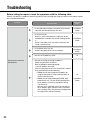
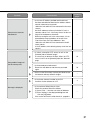
Troubleshooting.......................................................... 60
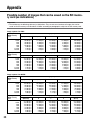
Appendix.................................................................... 68
Possible number of images that can be saved
on the SD memory card (as indications)................ 68
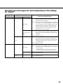
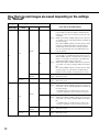
How the logs and images are saved depending
on the settings for "Alarm"..................................... 69
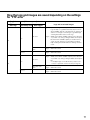
How the logs and images are saved depending
on the settings for "Manual".................................. 70
How the logs and images are saved depending
on the settings for "FTP error"............................... 71
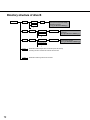
Directory structure of drive B................................. 72
Preface
About the user manuals
There are 2 sets of operating instructions for the WJ-GXE500 (NTSC model), WJ-GXE500E (PAL model) as follows.
• Installation Guide: Explains how to install and connect devices.
• Operating Instructions (PDF): Explains how to perform the settings and how to operate this unit.
Adobe® Reader® is required to read these operating instructions (PDF) on the provided CD-ROM.
When the Adobe® Reader® is not installed on the PC, download the latest Adobe® Reader® from the Adobe web
site and install it.
"WJ-GXE500" shown in the instructions and illustrations used in these operating instructions indicates the
WJ-GXE500, WJ-GXE500E.
The screens used in these operating instructions show the case of NTSC model.
Refer to the readme file on the provided CD-ROM for further information including the dedicated software, its version, and compatible cameras.
Trademarks and registered trademarks
• Microsoft, Windows, Windows Vista, Internet Explorer, ActiveX and DirectX are either registered trademarks or
trademarks of Microsoft Corporation in the United States and/or other countries.
• Adobe, the Adobe logo, and Reader are either registered trademarks or trademarks of Adobe Systems
Incorporated in the United States and/or other countries.
• SDHC logo is a trademark.
• Other names of companies and products contained in these operating instructions may be trademarks or registered trademarks of their respective owners.
Abbreviations
The following abbreviations are used in these operating instructions.
Microsoft® Windows® 7 Professional (64-bit) and Microsoft® Windows® 7 Professional (32-bit) are described as
Windows 7.
Microsoft® Windows Vista® Business SP1 (32-bit) is described as Windows Vista.
Microsoft® Windows® XP Professional SP3 is described as Windows XP.
Windows® Internet Explorer® 8.0, Windows® Internet Explorer® 7.0 and Microsoft® Internet Explorer® 6.0 are
described as Internet Explorer.
SDHC/SD memory card is described as SD card or SD memory card.
3
Viewer software
It is necessary to install the viewer software "Network Camera View 4" to display images on a PC.
This software can be installed directly from the network video encoder WJ-GXE500 or WJ-GXE500E (hereinafter,
the unit) or by double clicking "nwcv4setup.exe" on the CD-ROM provided, and then following the on-screen
instructions.
Important:
• The default setting of "Automatic installation of Viewer software" is
"On". Follow the instructions on page 66 when the message is displayed on the information bar of the browser.
• When the "Live" page is displayed for the first time, the install wizard of the ActiveX control required to display images from the camera will be displayed. Follow the instructions of the wizard.
• When the install wizard is displayed again even after completing
the installation of the ActiveX, restart the PC.
• The viewer software used on each PC should be licensed individually. The number of installations of the viewer software from the unit
can be checked on the [Upgrade] tab of the "Maintenance" page
(☞ page 22). Refer to your dealer for the software licensing.
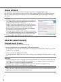
About the network security
Equipped security functions
The following security functions are featured in this unit.
q Access restrictions by the host authentication and the user authentication
It is possible to restrict users from accessing the unit by setting the host authentication and/or the user authentication to "On". (☞ Page 50)
w Access restrictions by changing the HTTP port
It is possible to prevent illegal access such as port scanning, etc. by changing the HTTP port number. (☞ Page
54)
Important:
• Leakage of information such as image data, authentication information (user name and password), alarm mail
information, FTP server information, DDNS server information, etc. can happen. Perform the countermeasure
such as the access restriction using the user authentication.
• After the unit is accessed by the administrator, make sure to close the browser for added security.
• Change the administrator password periodically for added security.
Note:
• When user authentication (authentication error) has failed to pass 8 times within 30 seconds using the same IP
address (PC), access to the unit will be denied for a while.
4
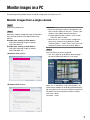
Monitor images on a PC
The following are descriptions of how to monitor images from the camera on a PC.
Monitor images from a single camera
Step 1
Start up the web browser.
Step 2
Enter the IP address designated using the Panasonic
Easy IP Setup software in the address box of the
browser.
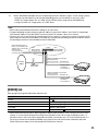
Example when entering an IPv4 address:
http://URL registered using IPv4 address
http://192.168.0.10/
Example when entering an IPv6 address:
http://URL registered using IPv6 address
http://[2001:db8::10]/
<Example of IPv4 access>
<Example of IPv6 access>
Important:
• When the HTTP port number is changed from "80",
enter "http://IP address of the unit + : (colon) + port
number" in the address box of the browser.
Example: When the port number is set to "8 080"
http://192.168.0.11:8080
• When the unit is in a local network, configure the
proxy server setting of the web browser (under
"Internet Options…" under "Tools" of the menu bar)
to bypass the proxy server for the local address.
Step 3
Press the [Enter] key on the keyboard.
→ The "Live" page will be displayed. Refer to page 7
for further information about the "Live" page.
When "On" is selected for "User authentication", the
authentication window will be displayed before displaying live images for the user name and password entries.
The default user name and password are as follows.
User name: admin
Password: 12345
5
Important:
• To enhance the security, change the password for the user "admin". It is recommended to change this password periodically.
• When displaying multiple H.264 (or MPEG-4) images on a PC, images may not be displayed depending on the
performance of the PC.
Note:
• When "H.264" is selected for "Video encoding format", H.264 video will be displayed. When "MPEG-4" is
selected, MPEG-4 images will be displayed.
• When multiple users are receiving audio, the frame rate of H.264 (or MPEG-4) images or the refresh interval of
JPEG images may be lower than the specified value.
• The maximum number of concurrent access user is 14 including users who are receiving H.264 (or MPEG-4)
images and users who is receiving JPEG images. Depending on the set values for "Bandwidth control (bit rate)"
and "Max bit rate (per client) *", the maximum concurrent access number may be less than 14 users. When 14
users are concurrently accessing, the access limit message will be displayed for users who subsequently
attempt to access. When "Multicast" is selected for "Transmission type" of "H.264" (or "MPEG-4"), only the first
user who accessed to monitor H.264 (or MPEG-4) images will be included in the maximum number. The second
and subsequent users who are monitoring H.264 (or MPEG-4) images will not be included in the maximum number.
• When "On" is selected for "H.264 transmission" (or "MPEG-4 transmission") (☞ pages 34 to 40), H.264 (or
MPEG-4) images will be displayed. When "Off" is selected, a JPEG image will be displayed. It is possible to display a JPEG image even when "On" is selected for "H.264" (or "MPEG-4 transmission").
• The refresh interval may become longer depending on a network environment, PC performance, photographic
subject, access traffic, etc.
<Refresh interval of JPEG images>
When "Ch1 only" is selected for "Ch selection"
When "On" is selected for "H.264 transmission" (or "MPEG-4 transmission")
• JPEG (VGA, QVGA, D1): 15 fps (NTSC model), 12.5 fps (PAL model)
When "Off" is selected for "H.264 transmission" (or "MPEG-4 transmission")
• JPEG (VGA, QVGA, D1): 30 fps (NTSC model), 25 fps (PAL model)
When "Ch1-2" is selected for "Ch selection"
When "On" is selected for "H.264 transmission" (or "MPEG-4 transmission")
• JPEG (VGA, QVGA, D1): 15 fps (NTSC model), 12.5 fps (PAL model)
When "Off" is selected for "H.264 transmission" (or "MPEG-4 transmission")
• JPEG (VGA, QVGA, D1): 15 fps (NTSC model), 12.5 fps (PAL model)
When "Ch1-3" is selected for "Ch selection"
When "On" is selected for "H.264 transmission" (or "MPEG-4 transmission")
• JPEG (VGA, QVGA, D1): 10 fps (NTSC model), 8.3 fps (PAL model)
When "Off" is selected for "H.264 transmission" (or "MPEG-4 transmission")
• JPEG (VGA, QVGA, D1): 15 fps (NTSC model), 12.5 fps (PAL model)
6
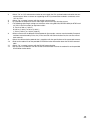
When "Ch1-4" is selected for "Ch selection"
When "On" is selected for "H.264 transmission" (or "MPEG-4 transmission")
• JPEG (VGA, QVGA): 3 fps (NTSC model), 3.1 fps (PAL model)
• JPEG (D1): 2 fps (NTSC model), 2.1 fps (PAL model)
When "Off" is selected for "H.264 transmission" (or "MPEG-4 transmission")
• JPEG (VGA, QVGA, D1): 15 fps (NTSC model), 12.5 fps (PAL model)
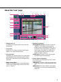
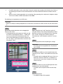
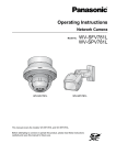
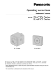
About the "Live" page
!6 !7
q
!8
!9 @0 @1
@2
@3
w
e
r
t
@4
y
u
!4
i
!5
o
!0
!1
!2
q [Setup] button (*1)
The button will turn green and the setup menu will
be displayed.
w [Live] button
Display the "Live" page. The button will turn green
and the "Live" page will be displayed.
e [1] to [4] buttons
The button will turn green and the "Live" page of the
corresponding channel will be displayed. It is possible to select a desired channel by clicking the [1] to
[4] buttons.
r [Multi-screen] buttons
Images from multiple cameras can be displayed on
a multi-screen by registering cameras on the setup
menu. (☞ Page 11)
!3
t [Compression] buttons
[H.264]/[MPEG-4] button: The letters "H.264" (or
"MPEG-4") will turn green and an H.264 (or
MPEG-4) image will be displayed. When "On" is
selected for "H.264 transmission" (or "MPEG-4
transmission") of "H.264(1)" (or "MPEG-4(1)"),
the [H.264] (or [MPEG-4]) button will be displayed. (☞ Pages 34 and 37)
[JPEG] button: The letters "JPEG" will turn green
and JPEG image will be displayed.
y [Image capture size] buttons
These buttons will be displayed only when a JPEG
image is displayed.
[VGA] button: The letters "VGA" will turn green and
images in the main area will be displayed in VGA
size.
[QVGA] button: The letters "QVGA" will turn green
and images in the main area will be displayed in
QVGA size.
7
u [AUX] buttons (*2)
[AUX] button will become available only when "AUX
output" is selected for "Terminal 3" on the setup
menu. (☞ Page 45)
[Open] button: The letters "Open" will turn green
and the status of AUX connector will be open.
[Close] button: The letters "Close" will turn green
and the status of the AUX connector will be
closed.
i [Rec. on SD] button (*2)
This button will be displayed only when "Manual" is
selected for "Save trigger" on the setup menu.
(☞ Page 31)
Click this button to manually record images on the
SD memory card. Refer to page 12 for descriptions
of how to manually record images on the SD memory card.
o [Log] button (*1)
[List] button will be displayed only when "On" is
selected for "Save logs" on the setup menu.
(☞ page 33) When this button is clicked, the log list
will be displayed and images saved on the SD
memory card can be played. Refer to pages 17 to
20 for further information about the log list and for
how to play images on the SD memory card.
!0 [Zoom] buttons (*2)
: Click this button to adjust the zoom ratio
to the WIDE side.
: Click this button to set the zoom ratio to
x1.
: Click this button to adjust the zoom ratio
to the TELE side.
!1 [Focus] buttons (*2)
: Click this button to adjust the focus automatically.
: Click this button to adjust the focus to the
"Near" side.
: Click this button to adjust the focus to the
"Far" side.
8
!2 Auto mode (*2)
Select an operation from the pull-down menu and
click the [Start] button. The selected operation will
start.
Click the [Stop] button to stop the operation.
The selected operation will stop when the camera
(panning/tilting/zooming/focusing) is operated.
Auto track: Performs auto track when the camera
supports auto track (AUTO TRACK).
Auto pan: Automatically pans between the start
position and the end position set in advance.
Even when the camera is operated for zooming
or focusing, the camera continues panning.
Preset position sequence: Automatically moves to
the preset positions orderly (start from the lowest preset position number).
Patrol 1-4: Operates the camera in accordance with
patrol function settings.
Note:
• To check if the camera supports auto track, refer to
the operating instructions of the camera.
• To activate auto pan, sort, preset position sequence
or patrol 1-4, it is required to perform the settings
on the setup menu of camera in advance. (☞ Page
41)
• While a camera controlled via the RS-485 communication interface is executing a patrol function, it is
impossible to start another one. Stop the current
patrol function before starting a new one.
!3 Control pad/buttons (*2)
: Left-click on the control pad to
adjust the horizontal/vertical
position of the camera (panning/
tilting).
Panning/tilting speed will be
faster if a clicked point gets farther from the center point of the control pad.
It is also possible to pan/tilt the camera by dragging
the mouse. Zoom and focus can be adjusted by
right-clicking. When an upper/lower area of the control pad is right-clicked, the displayed image will be
zoomed in/out on. When a left/right area is rightclicked, the focus will be adjusted to the Near/Far
side.
!4 [Brightness] buttons (*2)
: The displayed image will be darker.
: The adjusted brightness will return to the
default brightness.
: Image will be brighter.
Note:
• When the [Brightness] buttons are clicked while the
camera is at the preset position, the adjusted brightness will automatically be registered for the current
preset position.
!5 Preset (*2)
Select a preset position from the pull-down menu
and click the [Go] button. The camera will move to
the selected preset position. When "Home" is
selected, the camera will move to the home position. To activate preset positions and home position,
it is required to configure the settings on the SETUP
MENU of camera in advance. (☞ Page 41)
!6 Unit title
The unit title entered for "Unit title" on the [Basic]
tab will be displayed. (☞ Page 30)
!7 Camera title
The camera title entered for "Camera title" on the
[Basic] tab will be displayed. (☞ Page 30)
!8 [Alarm occurrence indication] button (*2)
This button will be displayed at an alarm occurrence, and the channel of alarm occurrence (one of
q to r buttons) will light. When the button is
clicked, the button will disappear and the alarm output connector will be reset. (☞ Page 13)
!9 [Full screen] button
Images will be displayed on a full screen. To return
to the "Live" page, press the [Esc] key.
@0 [One shot] button
Click this button to take a picture (a still picture).
The picture will be displayed on a newly opened
window. When right-clicking on the displayed
image, the pop-up menu will be displayed. It is possible to save the image on the PC by selecting
"Save" from the displayed pop-up menu.
When "Print" is selected, printer output is enabled.
@1 [Mic input] button (*3)
Turns on/off the audio reception (hear audio from
the unit on a PC).
This button will be displayed only when "Mic input",
"Interactive(Half-duplex)" or "Interactive(Fullduplex)" is selected for "Audio transmission/reception" on the setup menu. (☞ Page 41)
When this button is clicked, the button will turn into
the
button and audio from the unit will not be
heard. Audio volume can be adjusted (Low/Middle/
High) by moving the volume cursor
.
Note:
• Mic input is available on Ch1 only.
@2 [Audio output] button (*3)
Turns on/off the audio transmission (play audio from
the PC on the unit speaker).
This button will be displayed only when "Audio output", "Interactive(Half-duplex)" or "Interactive(Fullduplex)" is selected for "Audio transmission/reception" on the setup menu. (☞ Page 41)
The button will blink during the audio transmission.
When this button is clicked, the button will turn into
button and audio from the unit will not be
the
heard. Audio volume can be adjusted (Low/Middle/
High) by moving the volume cursor
.
Note:
• Audio output is available on Ch1 only.
• When a user is using the audio transmission function with "Interactive(Half-duplex)" selected, the
[Mic input] button and the [Audio output] button will
be inoperable for the other users. When
"Interactive(Full-duplex)" is selected, the transmission button is inoperable for other users.
• Possible duration of audio transmission is up to 5
minutes per transmission. When 5 minutes have
passed, audio transmission will automatically stop.
To turn the audio transmission function on, click the
[Audio output] button again.
• When the unit is restarted, the adjusted volume level
(for both the audio transmission and reception) will
return to the level that had been set on the [Audio]
tab on the setup menu. (☞ Page 41)
• Actual volume level will change in three steps even
though the volume cursor can be adjusted minutely.
9
@3 SD recording status indicator
The status of the SD recording can be checked with
this indicator.
When the SD recording starts, this indicator will light
red. When the SD recording stops, this indicator will
go off.
This indicator will be displayed only when "Manual"
is selected for "Save trigger" on the setup menu.
(☞ Page 31)
@4 Main area
Images from the camera will be displayed in this
area.
The current time and date will be displayed according to the settings configured for "Time display format" and "Date/time display format". (☞ Page 30)
Click a desired point in the main area on the "Live"
page that is to be the center of the angle of view.
The camera moves to adjust the position in order to
set the clicked point as the center.
*1 Only operable by users whose access level is "1.
Administrator"
*2 Only operable by users whose access level is "1.
Administrator" or "2. Camera control" when "On" is
selected for "User auth." (☞ page 50).
*3 Operable by users who belong to the access level
selected for "Permission level of audio trans./
recep." on the [Audio] tab of the "Image/Audio"
page. Refer to page 50 for further information about
the access level.
Note:
• When operated by a lower access level user, images
displayed on the screen may be changed temporarily. This does not affect operation of the camera.
10
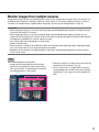
Monitor images from multiple cameras
Images from multiple cameras can be displayed on a multi-screen. Images from 4 cameras (up to 16 cameras) can
be displayed simultaneously. To display images on a multi-screen, it is necessary to register cameras in advance.
4 cameras can be registered as a group and up to 4 groups (16 cameras) can be registered. (☞ Page 44)
Important:
• When displaying images on a 16-screen, panning, tilting and zooming operations become unavailable for images from the Panasonic PTZ cameras.
• When displaying images on a 4-screen, panning, tilting and zooming operations become available only for
images from the Panasonic PTZ cameras. Refer to the readme file on the provided CD-ROM for further information about the compatible PTZ cameras and their versions.
• Only JPEG images can be displayed on a multi-screen.
• Audio will not be heard.
• When the power is turned off or the Ethernet cable is disconnected while displaying images, displaying images
on a multi-screen from the "Live" page will become unavailable.
• Regardless of the settings of the registered device, the images will be displayed altered to the aspect ratio of
4:3 on a multi-screen.
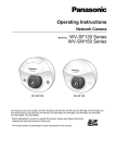
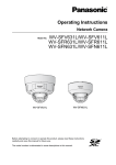
Step1
Click the desired [Multi-screen] button.
→ Images from the registered cameras will be displayed on a selected multi-screen (screen can be
split up to 16 areas). The following are instructions
when displaying on a 4-split screen.
q
q To display images on a single screen, click the [Live]
button or one of the buttons [1] to [4].
w Click a camera title. Live images from the camera
corresponding to the clicked camera title will be displayed on the "Live" page of the newly opened window.
w
11
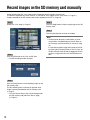
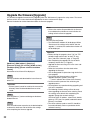
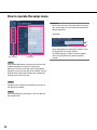
Record images on the SD memory card manually
Images displayed on the "Live" page can be recorded on the SD memory card manually.
This button is operable only when "Manual" is selected for "Save trigger" on the setup menu. (☞ Page 31)
Images recorded on the SD memory card can be copied onto the PC. (☞ Page 19)
Step1
Step 4
Display the "Live" page. (☞ Page 5)
Click the [Stop] button to stop saving images on the SD
memory card.
Step 5
Click the [Close] button to close the window.
Step 2
Click the [SD] button in the "Rec. on SD" box.
→ The SD recording window will open.
Step 3
Click the [Start] button to start recording images on the
SD memory card.
The SD recording status indicator will light red while
images are being recorded on the SD memory card.
(☞ Page 7)
→ The save interval (frame rate) can be configured on
the [SD memory card] tab of the "Basic" page.
(☞ Page 31)
12
Note:
• The destination directory to which data are to be
saved will be a fixed directory on Drive B. Refer to
the "Directory structure of drive B" section (☞ page
72).
It is possible to obtain image data saved on Drive B
by clicking the [Execute] button of "Access img." on
the [SD memory card] tab and by logging in the unit
to access images from the user authentication window.
Action at an alarm occurrence
The alarm action (action at an alarm occurrence) will be performed when the following alarms occur.
Alarm type
Terminal alarm: When connecting an alarm device such as a sensor to the EXT I/O terminals of the unit, the alarm
action will be performed when the connected alarm device is activated. (☞ Page 45)
VMD alarm: When motion is detected in the set VMD area, the alarm action will be performed. (☞ Page 45)
* VMD stands for "Video Motion Detection".
Command alarm: When a Panasonic alarm protocol is received from the connected device via a network, the
alarm action will be performed. (☞ Page 45)
Camera site alarm: When a camera connected to a Video input connector detects an alarm by alarm sensors or
cameras' motion detectors, etc., and the unit receives the alarm input signal from the camera, the alarm action
will be performed. (☞ Page 45)
Video loss: When the loss of video input signals is detected due to coaxial cable disconnections or camera troubles, the alarm action will be performed. (☞ Page 45)
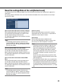
Action at an alarm occurrence
• Display the [Alarm occurrence indication] button on the "Live" page. (☞ Page 7)
The alarm occurrence indication button will be displayed on the "Live" page at an alarm occurrence.
Important:
• When "Polling (30 sec)" is selected for "Alarm status update mode" (☞ page 30), the [Alarm occurrence indication] button will be refreshed in 30-second intervals. For this reason, it may take a maximum of 30 seconds until
the [Alarm occurrence indication] button is displayed on the "Live" page at an alarm occurrence.
• Notify of alarm occurrences to the device connected to the alarm connector
It is possible to output signals from the alarm connector on the rear of the unit and sound the buzzer when an
alarm occurs.
The settings for the alarm output can be configured on the [Alarm] tab of the "Alarm" page. (☞ Page 45)
• Save images on the SD memory card
When an alarm occurs, images will be saved on the SD memory card. The settings to save images on the SD
memory card can be configured on the [SD memory card] tab of the "Basic" page. (☞ Page 31)
• Transmit an image onto a server automatically
An alarm image can be transmitted at an alarm occurrence to the server designated in advance. The settings
required to transmit an alarm image to a server can be configured on the [Alarm] tab of the "Alarm" page and
the [FTP] tab of the "Server" page (☞ pages 45 and 52).
Important:
• Select "FTP error" for "Save trigger" on the [SD memory card] tab when using the SD memory card. When
"Alarm input" or "Manual" is selected for "Save trigger", an alarm image will not be transmitted at an alarm
occurrence to the FTP server. (☞ Page 31)
13
• Notify of alarm occurrences by e-mail
Alarm mail (alarm occurrence notification) can be sent at an alarm occurrence to the e-mail addresses registered
in advance.
The settings for alarm mail can be configured in the "Mail notification" section of the [Notification] tab of the
"Alarm" page and the [Mail] tab of the "Server" page (☞ pages 48 and 52).
• Notify of alarm occurrences to the designated IP addresses (Panasonic alarm protocol notification)
This function is available only when a Panasonic device, such as the network disk recorder, is connected to the
system. When "On" is selected for "Panasonic alarm protocol notification", the connected Panasonic device will
be notified that the unit is in the alarm state. The settings for Panasonic alarm protocol can be configured in the
Panasonic alarm protocol section of the [Notification] tab of the "Alarm" page. (☞ Page 48)
14
Transmit images onto an FTP server
Images can be transmitted to an FTP server. By configuring the following settings, transmission of images captured
at an alarm occurrence or captured at a designated interval to an FTP server will become available.
Important:
• When using this function, set the user name and the password to access the FTP server to restrict users who
can log into the FTP server.
• To transmit images to the FTP server, select "Not use" for "SD memory card", or select "FTP error" for "Save
trigger" on the [SD memory card] tab of the "Basic" page. (☞ Page 31)
Transmit an alarm image at an alarm occurrence (Alarm image transmission)
An alarm image can be transmitted at an alarm occurrence to the FTP server. To transmit alarm images to an FTP
server, it is necessary to configure the settings in advance.
The settings for the FTP server can be configured on the [FTP] tab of the "Server" page. (☞ Page 52)
The alarm image transmission function can be turned on/off on the [Alarm] tab of the "Alarm" page. (☞ Page 45)
Note:
• Depending on the network traffic, the number of the transmitted images may not reach the set number of images
to be transmitted.
• Alarm images failed to be transmitted to the FTP server at an alarm occurrence will not be saved on the SD
memory card.
Transmit images at a designated interval or period (FTP periodic image transmission)
Images can be transmitted at a designated interval or period. To transmit images at a designated interval or period,
it is necessary to configure the settings in advance.
The settings for the FTP server can be configured on the [FTP] tab of the "Server" page. (☞ Page 52)
It is possible to determine whether or not to use the FTP periodic image transmission function and to configure the
settings relating to alarm images and the schedule on the [FTP img. trans.] tab of the "Network" page. (☞ Page 56)
Note:
• Depending on the line speed or the traffic, images may not be transmitted at the designated interval.
• When "On" is selected for both the alarm image transmission function and the FTP periodic image transmission
function, the alarm image transmission function will be given priority over the FTP periodic image transmission
function. Therefore, images may not be transmitted at the interval designated on the "FTP periodic image transmission" setting.
15
Save images on the SD memory card when images have failed to be transmitted using the FTP periodic image transmission function
Images that have failed to be transmitted using the FTP periodic image transmission can be saved automatically on
the SD memory card. Images saved on the SD memory card can be obtained from the [SD memory card] tab of the
"Basic" page. (☞ Page 31)
To use the SD memory recording function featured in Panasonic’s network disk recorder, select "Off" for "FTP periodic image transmission" (☞ page 56) and "FTP error" for "Save trigger" (☞ page 31).
We make no guarantee for any damages of files on the SD memory card incurred by malfunction or error occurrence in files saved in the SD memory card regardless of what the cause may be.
Note:
• Depending on the settings and status of use, not all images failed in the FTP periodic transmission may not be
saved on the SD memory card.
16
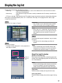
Display the log list
The logs will be displayed in the following list forms.
• Alarm log:
Logs of the alarm occurrences such as time and date of the alarm occurrences and the
alarm type will be displayed.
• Manual log:
Logs filed when images have been manually recorded on the SD memory card will be displayed.
• FTP trans. error log: Logs filed when the FTP periodic image transmission function has failed will be displayed.
Each log list can be displayed only when "On" is selected for "Save logs" on the [Log] tab of the "Basic" page
(☞ page 33) respectively.
Step1
Important:
Display the "Live" page. (☞ Page 5)
• Only a single user can operate the log list window.
Other users cannot access the log list window.
Note:
• When "Not use" is selected for "SD memory card",
the error log list of manual saving and the FTP periodic image transmission function will not be displayed.
Step 3
Click the desired log type listed below "Log" to display
the log list.
→ The log list of the selected log type will be displayed.
Step 2
Click the [List] button.
→ The log list will be displayed in a newly opened window (log list window).
Note:
• When saved images are on the SD memory card,
clicking the time and date of the alarm occurrence
will display the respective images. (☞ Page 19)
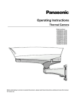
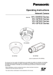
About the log list window
Number of
the listed
logs
[Number of the listed logs]
Total number of the logs of the selected log type and a
number of the log being displayed on the top of the log
list will be displayed.
Note:
• Enter the desired log number and press the [Enter]
key on the keyboard. The log of the designated
number will be displayed on the top of the log list.
[Top] button
Click this button to display the log listed at the top.
[Prev. page] button
Click this button to display the previous page of the log
list.
17
Note:
• When the mouse button is held down while placing
the mouse pointer on the [Prev. page] button, the
displayed log number will be decremented.
When the mouse button is released, the decrement
of the log number will stop and the log number displayed at the moment when the mouse button is
released will be the top of the currently displayed
page.
[Next page] button
Click this button to display the next page of the log list.
Note:
• When the mouse button is held down while placing
the mouse pointer on the [Next page] button, the
displayed log number will be incremented.
When the mouse button is released, the decrement
of the log number will stop and the log number displayed at the moment when the mouse button is
released will be the top of the currently displayed
page.
[Last] button
Click this button to display the log listed at the bottom.
[Time & date]
Time and date when each log has been filed will be displayed.
Note:
• When "Off" is selected for "Time display format" (☞
page 30), time and date of alarm occurrence will be
displayed in 24-hour format.
• The recording timing of logs are as follows.
Alarm log: Alarm occurrence time and date will be
filed as a log.
Manual log: Time and date when recording of
images onto the SD memory card started will be
filed as a log. When recording are performed
sequentially, logs will be filed every one hour.
FTP trans. error log: Logs will be filed every one
hour.
[Ch]
The channel will be displayed.
18
[Event]
The event type will be displayed.
The event types will be displayed only when displaying
the alarm log list.
TRM1: Alarm by alarm input to Terminal 1
TRM2: Alarm by alarm input to Terminal 2
TRM3: Alarm by alarm input to Terminal 3
VMD: Alarm by VMD alarm
COM: Alarm by command alarm
CAM: Alarm by camera site alarm
LOSS: Alarm at a video loss occurrence
[SD memory card]
Available capacity and the original capacity of the SD
memory card will be displayed.
The displayed descriptions are the same descriptions
displayed as "Remaining capacity" on the [SD memory
card] tab. (☞ Page 31)
[Delete] button
Click this button to delete the currently displayed log
list.
When using the SD memory card, images associated
with the log list will also be deleted.
Important:
• When many images are saved on the SD memory
card, it will take some time to complete the deletion.
• In the process of the deletion, only logs will be
saved, and it is impossible to save images newly.
• Do not turn off the power of the unit until the deletion is complete.
When the power of the unit is turned off in the process of the deletion, some images may remain on
the SD memory card.
In this case, click the [Delete] button on the same
log list window used to delete the logs.
[Download] button
Click this button to download all logs of the selected
log list as a file onto the PC.
[Close] button
Click this button to close the log list window.
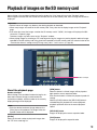
Playback of images on the SD memory card
When clicking a time and date listed on the log list window, the "Live" page will turn to the "Playback" page.
When images associated with the clicked time and date are on the SD memory card, the first image of them will be
displayed.
Important:
• Refresh interval of images may become slow during playback or download.
• When many images are saved on the SD memory card, it may take time to display images on the "Playback"
page.
• Even when the size of the images saved on the SD memory card is "QVGA", the images will be played in VGA
size on the "Playback" page.
Therefore, images may look coarse on the "Playback" window.
• When playing images by selecting an FTP error log on the log list, images may not be played in order of images
recorded on the SD memory card if they have been recorded on the SD memory card with selected value for the
"Transmission interval" setting on the [FTP img. trans.] tab is "1 min" or less. (☞ Page 56)
Number of images
About the playback page
Number of images
When clicking a time and date listed on the log list window, total number of images associated with the
clicked time and date, and the number of the currently
displayed image will be displayed.
Note:
• Enter the desired number of image and press the
[Enter] key on the keyboard. The image of the designated number will be displayed.
[Ch No.]
Select the channel number to play back images from
the "FTP trans. error log" list.
[REW] button
When this button is clicked, images will be played at
high speed in reverse sequential order.
Each time the button is clicked, the playback speed will
change.
When the [PLAY] button or the [REV PLAY] button is
clicked during fast playback/fast reverse playback,
playback speed will return to the normal playback
speed.
[REV PLAY] button
Images will be played in reverse sequential order.
[PLAY] button
Images will be played in sequential order.
19
[FF] button
When this button is clicked, images will be played at
high speed in sequential order.
Each time the button is clicked, the playback speed will
change.
When the [PLAY] button or the [REV PLAY] button is
clicked during fast playback/fast reverse playback,
playback speed will return to the normal playback
speed.
When the mouse button is released, the increment
of the image number will stop and the image number displayed at the moment when the mouse button is released will be displayed.
[LAST] button
The last image will be displayed.
■ Browse
[TOP] button
The first image will be displayed.
[PREV. IMAGE] button
The previous frame will be displayed and paused when
this button is clicked during playback.
Each time this button is clicked during pausing, the
frame previous to the currently displayed frame will be
displayed.
Note:
• When the mouse button is being held while placing
the mouse pointer on this button, the displayed
image number will be decremented.
When the mouse button is released, the decrementing of the image number will stop and the image
corresponding to the currently displayed number
will be displayed.
[PAUSE] button
Playback will be paused when this button is clicked
during playback. Playback will resume when this button
is clicked during pausing.
[STOP] button
Playback will stop and the "Playback" window will turn
to the "Live" page.
[NEXT IMAGE] button
The next frame will be displayed and paused when this
button is clicked during playback.
Each time this button is clicked during pausing, the
frame next to the currently displayed frame will be displayed.
Note:
• When the mouse button is held down while the
mouse pointer is on this button, the image number
will be incremented.
20
[Start] button
The selected image will be downloaded onto the PC.
Before downloading images, designate the destination
directory in advance. (☞ Page 33)
The following window will be displayed when the [Start]
button is clicked.
Select the image to be downloaded, and then click the
[OK] button.
All: All images saved at the selected time and date will
be downloaded.
Current image: Only the currently displayed image will
be downloaded.
Download range: Images in the designated range of
number of images will be downloaded.
Note:
• When downloading images from the "FTP trans.
error log" list, only images from the channels selected for "Ch No." are available.
• When the [Cancel] button is clicked in the process
of the download, the download will be canceled.
In this case, images already downloaded before
clicking the [Cancel] button will be saved on the PC.
[Browse] button
When successfully logged in after the user authentication process, a folder on the SD memory card in which
images are saved will be displayed.
Maintenance of the unit [Maintenance]
Check the system log [System log]
It is possible to check the system log on the [System log] tab of the "Maintenance" page on the setup menu.
Up to 4 000 system logs can be saved on the SD memory card when the SD memory card is inserted after selecting "Use" for "SD memory card" on the [SD memory card] tab (☞ page 31).
When "Not use" is selected for "SD memory card", up to 100 system logs can be saved on the built-in memory of
the unit.
When the saved system logs have reached the maximum number, the newer logs will overwrite the older system
logs. In this case, the oldest log is the first to be overwritten.
The system logs will be displayed in group of 100 logs each.
When using the SD memory card, the logs will be saved even when the power of this unit is turned off. When not
using the SD memory card, the logs will be deleted when the power of this unit is turned off.
[Next 100 >>]
When clicking "Next 100 >>", the next 100 system logs
will be displayed.
[<< Previous 100]
When clicking "<< Previous 100", the previous 100 system logs will be displayed.
[No.]
The serial number of the system log will be displayed.
[Time & date]
Time and date at the error occurrence will be displayed.
Note:
• When "Off" is selected for "Time display format" on
the [Basic] tab (☞ page 30), time & date of logs will
be displayed in 24-hour format.
[Error description]
The descriptions about the error will be displayed.
Refer to page 58 for further information about the system logs.
21
Upgrade the firmware [Upgrade]
It is possible to upgrade firmware on the [Upgrade] tab of the "Maintenance" page on the setup menu. The current
firmware of this unit can be checked and upgraded to the latest version on this page.
Contact the dealer for further information about the firmware upgrade.
Note:
• Refer to the readme file provided with the firmware
first and determine whether or not to initialize the
settings after the firmware upgrade.
Step 4
Click the [Execute] button.
→ The confirmation window will be displayed. When
"Do not reset the settings to the default after the
upgrade." is selected, the confirmation window will
not be displayed.
[Model no.], [MAC address], [Serial no.],
[Firmware version], [IPL version], [HTML version],
[IP address(IPv6)], [Viewer software installation
counter]
Information of each item will be displayed.
Step1
Contact the dealer and download the latest firmware
onto a PC.
Important:
• A blank (space) cannot be used for the name of the
directory where the downloaded firmware to be
saved.
Step 2
Click the [Browse...] button and designate the downloaded firmware.
Step 3
Click the radio button respective to the desired option
to determine whether or not to initialize the settings
after completing the firmware upgrade.
22
Important:
• Before starting the upgrade, select "Off" for "FTP
periodic image transmission" on the [FTP img.
trans.] tab of the "Network" page. (☞ Page 56)
• After completing the upgrade, be sure to delete
temporary internet files. (☞ Page 64)
• Upgrade the firmware using a PC in the same subnet as the unit.
• Follow the instructions from the dealer when
upgrading the firmware.
• Use the designated file (extension: img) for the firmware upgrade.
• The name of the firmware to be used for the
upgrade should be "gxe500_xxxxx.img".
* ("xxxxx" indicates the version of the firmware.)
• Do not turn off the power of the unit during the
upgrade process.
• Do not perform any operation during upgrading and
wait until it completes.
• The following network settings will not be reset
when upgrading the firmware after selecting "Reset
the settings to the default after completing the
upgrade. (Except the network settings)".
On/Off for DHCP, IP address, subnet mask, default
gateway, HTTP port, line speed, bandwidth control
(bit rate), time & date
• The viewer software used on each PC should be
licensed individually. Refer to your dealer for the
software licensing.
Reset the settings/Reboot the unit [Default reset]
It is possible to reset the settings or reboot the unit on the [Default reset] tab of the "Maintenance" page on the
setup menu.
The settings and the HTML data of the unit can be initialized and reboot of the camera and the unit can be performed on this page.
[Reset to the default (Except the network settings)]
Click the [Execute] button to reset the settings of the
unit and RS-485 command table to the default. Note
that the network settings will not be reset.
It is impossible to operate the unit for around 2 minutes
after the initialization.
Note:
• The following network settings will not be reset.
On/Off for DHCP, IP address, subnet mask, default
gateway, HTTP port, line speed, bandwidth control
(bit rate), time & date
[Load the default HTML files (setup menu).]
Click the [Execute] button to reset the settings of the
unit, RS-485 command table and HTML file to the
default. Note that the network settings will not be reset.
It is impossible to operate the unit for around 2 minutes
after the initialization.
[Reset to the default and load the default HTML
files.]
Click the [Execute] button to reset the settings of the
unit, RS-485 command table and HTML file to the
default. Note that the network settings will not be reset.
It is impossible to operate the unit for around 5 minutes
after the initialization.
[Camera restart]
Click the [Execute] button to restart all the cameras
connected to the unit. After restart, it is impossible to
control the camera around 1 minute.
[Unit restart]
Click the [Execute] button to reboot the unit.
The unit will be inoperable for around 2 minutes after
the restart just as when the power is turned on.
Note:
• To initialize the network settings (☞ page 54), turn
off the power of the unit, then turn on the power
again while holding down the [INITIAL SET] button
on the unit for 5 seconds. Wait around 2 minutes
after releasing the button. The unit will start up and
the settings including the network settings will be
initialized.
Do not turn off the power of the unit until the initialization is complete and the SDHC/SD memory card
error LED lights up.
• The notification function allows users to provide the
notification of the error to the specified mail address
and an original alarm destination when an error such
as no SD memory card insertion after the reboot or
a locked SD memory card insertion occurs. (☞ Page
48)
Note:
• The following network settings will not be reset.
On/Off for DHCP, IP address, subnet mask, default
gateway, HTTP port, line speed, bandwidth control
(bit rate), time & date
23
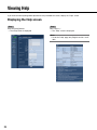
Viewing Help
If you want to know anything about operation or setup methods on screen, display the "Help" screen.
Displaying the Help screen
Step 1
Click the [Setup] button.
→ The setup screen is displayed.
Step 2
Click "Help >>".
→ The "Help" screen is displayed.
Note:
• As for the "Help" page, only English version is available.
24
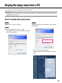
Display the setup menu from a PC
The settings of the unit can be configured on the setup menu.
Important:
• The setup menu is only operable by users whose access level is "1. Administrator". Refer to page 50 for how to
configure the access level.
How to display the setup menu
Step1
Display the "Live" page. (☞ Page 5)
Step 3
Click the [OK] button after entering the user name and
the password.
Step 2
Click the [Setup] button on the "Live" page.
→ The window with the user name and password entry
fields will be displayed.
→ The setup menu will be displayed.
Refer to page 28 for further information about this
menu.
25
How to operate the setup menu
Important:
• When there are two or more [Set] and [Execute] buttons on the page, click the respective button to the
edited setting item.
<Example>
A
A-1
Menu buttons
Setup page
Step1
Click the desired button in the frame on the left of the
window to display the respective setup menu.
When there are tabs at the top of the setup page displayed in the frame on the right of the window, click the
desired tab to display and configure the setting items
relating to the name of the tab.
Step 2
Complete each setting item displayed in the frame on
the right of the window.
Step 3
After completing each setting item, click the [Set] button to apply them.
26
When completing the setting items in field A, click
the [Set] button (A-1) below field (A).
The edited settings in field A will not be applied
unless the [Set] button (A-1) below field (A) is
clicked.
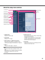
About the setup menu window
q [Setup] button
w [Live] button
e [Basic] button
!4 Status display
area
!3 Help >>
r [Image/Audio] button
t [Multi-screen] button
y [Alarm] button
u [Advanced func.] button
i [User mng.] button
!5 Setup page
o [Server] button
!0 [Network] button
!1 [Schedule] button
!2 [Maintenance] button
q [Setup] button
Display the "Setup" page.
w [Live] button
Display the "Live" page.
e [Basic] button to !2 [Maintenance] button
When one of these buttons is clicked, the corresponding setup page will be displayed. (☞ Page 28)
!4 Status display area
The name of the unit whose settings currently being
configured will be displayed.
In addition, when an alarm occurs while the [VMD
area] tab is being displayed, the alarm occurrence
indication button will be displayed.
!5 Setup page
Pages of each setup menu will be displayed. There
are tabs for some setup menus.
!3 Help >>
Display the "Help" page. (☞ Page 24)
Note:
• As for the "Help" page, only English version is available.
• Information such as available characters and setting
values for the setting items on each tab is
described.
27
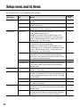
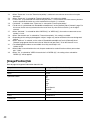
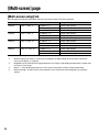
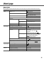
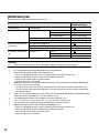
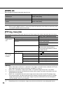
Setup menu and its items
The setup menu consists of the following menus and tabs.
Tab
Outline
Basic
Basic
Configure the basic settings such as time & date and camera titles.
30
SD memory card
Configure the operation specifications to save images on
the SD memory card.
31
Log
Configure the settings to save the "Alarm log" list, "Manual
log" list and "FTP trans. error log" list.
33
JPEG/H.264
[JPEG/H.264] tab will be displayed when "H.264" is selected for "Video encoding format".
Configure the settings relating to JPEG images such as
"Image capture size", "Image quality" and H.264 images
such as "Max bit rate (per client)", "Image capture size",
"Image quality", etc. in this section.
34
JPEG/MPEG-4
The [JPEG/MPEG-4] tab will be displayed when "MPEG-4"
is selected for "Video encoding format".
Configure the settings relating to JPEG images such as
"Image capture size", "Image quality" and MPEG-4 images
such as "Max bit rate (per client)", "Image capture size",
"Image quality", etc. in this section.
37
Image/Position
The setup menu of camera is displayed. Configure the settings relating to camera operations using the operation
panel. Refer to the operating instructions of camera for further information about the settings.
40
Audio
Configure relating to the settings relating to audio.
41
Coaxial/RS-485
Configure the settings relating to the video synchronization
type, camera control, cable compensation and RS-485
communication.
42
Multi-screen
Multi-screen
setup
Register the cameras from which images are to be displayed on a multi-screen.
44
Alarm
Alarm
Configure the settings relating to alarm actions, alarm images to be transmitted to an FTP server and alarm output terminals. In addition, the name for "AUX" on the "Live" page
can be changed.
45
VMD area
Configure the video motion detection areas.
46
Notification
Configure the settings relating to the alarm mail and
Panasonic alarm protocol.
48
XML notification
Configure the settings relating to the XML notification that
notifies the server or others of face detection information in
the XML format.
49
Face detection
Configure the settings relating to displaying of the frame to
be used for the face detection and the settings relating to
image attachment to the face detection information.
49
Image/Audio
Advanced func.
28
Reference
page
Menu page
Reference
page
Menu page
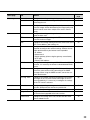
Tab
Outline
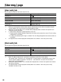
User mng.
User auth.
Configure the settings relating to the user authentication.
50
Host auth.
Configure the restriction settings of PCs (IP address) from
accessing the unit.
50
System
Configure the settings relating to the priority stream that can
transmit images without deteriorating the image quality and
refresh interval even when multiple users access concurrently.
51
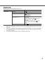
Mail
Configure the settings relating to the mail server used to
send the alarm mail.
52
FTP
Configure the settings relating to the FTP server used to
transmit the alarm images.
52
NTP
Configure the settings relating to the NTP server such as the
NTP server address, port number, etc.
53
Network
Configure the network settings. The following information is
required to configure the network settings. Contact the network administrator or your Internet service provider.
• IP address
• Subnet mask
• Default gateway (when using the gateway server/router)
• HTTP port
• Primary DNS address
54
DDNS
Configure the settings relating to DDNS. To use the DDNS
function, it is necessary to connect to the dedicated DDNS
server.
55
SNMP
Configure the settings relating to SNMP. It is possible to
check the status of the unit by connecting to the SNMP
manager. When using the SNMP function, contact the network administrator.
56
FTP img. trans.
Configure the settings relating to the periodic transmission
of images to an FTP server. To transmit images to an FTP
server periodically, it is necessary to configure the settings
of the FTP server in advance.
56
Schedule
Schedule
Configure the settings relating to schedules of alarm permission, VMD permission and access permission.
57
Maintenance
System log
Displays the system log.
21
Upgrade
Upgrade the firmware. The current firmware of this unit can
be checked and upgraded to the latest version.
22
Default reset
Configure the settings of this unit, initialize and the HTML
data or reboot the unit.
23
Server
Network
29
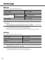
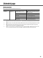
[Basic] page
[Basic] tab
Refer to page 28 for general information about this tab.
Setup items
Setting values (Underlined: default)
Unit title
(Default: WJ-GXE500)
Camera title
Time & date
Ch1
(Default: WJ-GXE500 Ch1)
Ch2
(Default: WJ-GXE500 Ch2)
Ch3
(Default: WJ-GXE500 Ch3)
Ch4
(Default: WJ-GXE500 Ch4)
Date/time *1
2010/01/01 00:00:00 - 2035/12/31 23:59:59
Time display format
24 h/12 h/Off
Date/time display format *2
DD/MM/YYYY (Default for the PAL model)
MM/DD/YYYY
DD/Mmm/YYYY
YYYY/MM/DD
Mmm/DD/YYYY (Default for the NTSC model)
Summer time (daylight saving)
In/Out
Camera title on screen
On/Off
Camera title on
screen (0-9, A-Z)
Ch1 - Ch4
(Default: None (blank))
OSD position
OSD Position
Upper left/Lower left/Upper right/Lower right
Display style
Opaque/Transparent
SD memory card error LED *3
On/Off
Alarm status update mode *4 *5
Polling(30sec)/Real time
Alarm status reception port *6
1 - 65 535 (Default: 31 004)
Automatic installation of viewer software *7 *8
On/Off
Important:
*7
• It is impossible to display images and to receive/transmit audio between the unit and the PC when the
viewer software "Network Camera View 4" is not installed on the PC.
*8
• The number of the viewer software installations can be checked on the [Upgrade] tab of the
"Maintenance" page.
*1
*2
30
• The default time & date is calculated based on the manufacture date & time.
• When "10.04.01 13:10:00" is set for "Date/time" after selecting "24h" for "Date/time display format", time
& date will be respectively displayed as follows.
DD/MM/YYYY:
01/04/2010 13:10:00
MM/DD/YYYY:
04/01/2010 13:10:00
DD/Mmm/YYYY:
01/Apr/2010 13:10:00
YYYY/MM/DD:
2010/04/01 13:10:00
Mmm/DD/YYYY:
Apr/01/2010 13:10:00
*3
*4
*5
*6
• When "On" is selected, the SD memory card error LED will light when data cannot be saved on the SD
memory card.
• Select the interval to refresh the alarm occurrence indication button, the [AUX] buttons and the SD recording status indicator on the "Live" page.
• Depending on the network environment, notification may not be provided in real time.
• The following port numbers are unavailable since they are already in use.
20, 21, 23, 25, 42, 53, 67, 68, 69, 80, 110, 123, 161, 162, 995, 10669, 10670
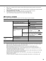
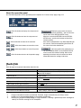
[SD memory card] tab
Refer to page 28 for general information about this tab. Refer to page 12 for how to operate.
Setup items
SD memory card *1 *2
Setting values (Underlined: default)
SD memory card
Use/Not use
Remaining capacity notification *3
50%/20%/10%/5%/2%
Save trigger *4
FTP error/Alarm input/Manual
Ch1/Ch2/Ch3/Ch4
Overwrite *5
On/Off
File name *6
(Default: None (blank))
Image saving interval/
Number of images to be
saved *7
Image saving
interval
NTSC model:
0.1fps/0.2fps/0.33fps/0.5fps/1fps
PAL model:
0.08fps/0.17fps/0.28fps/0.42fps/1fps
Number of imag- 10pics/20pics/30pics/50pics/100pics/
es to be saved
200pics/300pics/500pics/1000pics/
2000pics/3000pics
Image capture size *8
SD memory card information
Remaining capacity *9
SD memory card images
Access img. *11 *12
QVGA/VGA
Format *10
Important:
*1
• When the image refresh interval is short, notification/recording timing or interval may become incorrect.
• Select "Not use" when operating without an SD memory card.
• Before removing the SD memory card from the unit, it is necessary to select "Not use" first.
• After inserting the SD memory card, it is necessary to select "Use" to use the SD memory card.
• When playing or downloading images saved on the SD memory card, it is necessary to select "On" for
"Save logs" on the [Log] tab (☞ page 33) in advance.
• There are limited times to overwrite on an SD memory card. When having a high frequency of overwriting,
the lifetime of the SD memory card may become shorter.
• When the setting is changed between "Use" and "Not use" while another user is during operation, the
operation will be canceled.
• The data writing speed will go down after data are repeatedly written down on an SD memory card.
31
*10
*11
*2
*3
*4
*5
*6
*7
*8
*9
32
• Use the SD memory card after formatting it using the [SD memory card] tab.
• Before formatting the SD memory card, it is necessary to select "Use" for "SD memory card" and "Off" for
"FTP periodic image transmission" on the [FTP img. trans.] tab of the "Network" page (☞ page 54).
• It is impossible to access the SD memory card during the process of formatting.
• When an SD memory card is formatted while another user is during operation, the operation will be canceled.
• All data saved on the SD memory card will be deleted when the SD memory card is formatted.
• Do not turn off the power of the unit during the process of formatting.
• After formatting the SD memory card, available size may be smaller than the total size since the default
directory is automatically created in the SD memory card.
• Recommended SDHC/SD memory card
Manufactured by Panasonic (option)
SDHC memory card: 4 GB, 8 GB, 16 GB, 32 GB
SD memory card: 256 MB, 512 MB, 1 GB, 2 GB
(miniSD card and micro SD card excluded)
• It may sometimes be impossible to operate when another user is accessing images on the SD memory
card. this case, retry later.
• Depending on the settings of a proxy server or a firewall, images may not be obtained via a network.
• Notification/recording may also not be performed correctly as configured when multiple users are receiving images.
• When "D1" is selected for "Image capture mode", it is impossible to save images on the SD memory card.
• When the mail notification function or the Panasonic alarm protocol function is used to provide notification
of the remaining space of the SD memory card, select a level to be notified at from the following.
• Select "FTP error" when using the FTP periodic transmission function and when images are to be transmitted to the FTP server at an alarm occurrence.
• When selecting "Alarm input", select the channel to save the images on the SD memory card.
• The overwrite setting will be as follows according to the "Save trigger" setting.
FTP error:
Will not be overwritten.
Alarm input: Will be overwritten.
Manual:
Can be determined by selecting "On" or "Off" for "Overwrite".
• Enter the file name used for the image to be saved on the SD memory card. The file name will be as follows.
File name:
["Entered file name" + "Time and date (year/month/day/hour/minute/second)"] + "Serial
number" (☞ Page 56)
• When "FTP error" is selected for "Save trigger", images will be saved with the file name entered on the
[FTP img. trans.] tab of the "Network" page. (☞ Page 56)
• When selecting "Alarm input" for "Save trigger", select the image saving interval and the number of images to be saved. When selecting "Manual", select the image saving interval.
• When selecting "Manual" for "Save trigger", select the image capture size to save the images.
• When "FTP error" is selected for "Save trigger", images will be saved with the image capture size selected
on the [FTP img. trans.] tab of the "Network" page. (☞ Page 56)
• When "Alarm input" is selected for "Save trigger", images will be saved with the image capture size
selected on the [Alarm] tab of the "Alarm" page. (☞ Page 45)
• Total capacity and remaining space of the SD memory card will be displayed.
• Depending on the status of the SD memory card, the size indications will differ as follows.
--------KB/--------KB: No SD memory card is inserted. Failed to obtain available capacity due to error, etc.
********KB/********KB: The SD card memory is unformatted, or locked, etc.
*12
• It is necessary in advance to select "Allow" for "FTP access to unit" on the [Network] tab of the "Network"
page. (☞ Page 54)
• When logging in the unit to access images, drive B will be displayed first.
Images are saved in different directories according to "Save trigger".
Move to the directory corresponding to the desired images and copy them. Refer to page 72 for further
information about the directory structure.
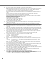
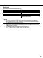
[Log] tab
Refer to page 28 for general information about this tab. Refer to page 17 for how to operate.
Setup items
Alarm
Manual
FTP error
Setting values (Underlined: default)
Save logs
On/Off
Name of the destination directory for
downloaded images
(Default setting: C:\nwcam)
Save logs
On/Off
Name of the destination directory for
downloaded images
(Default setting: C:\nwcam)
Save logs *1
On/Off
Name of the destination directory for
downloaded images
(Default setting: C:\nwcam)
Important:
*1
• When "Name w/o time&date" is selected for "File name" on the [FTP img. trans.] tab on the "Network"
page, FTP error log and associated will not be saved. (☞ Page 56)
33
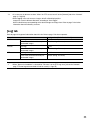
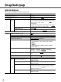
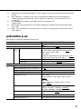
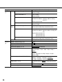
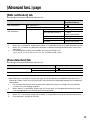
[Image/Audio] page
[JPEG/H.264] tab
Refer to page 28 for general information about this tab.
Setup items
Setting values (Underlined: default)
Image capture mode *1 *2
VGA/D1
Ch selection *1
Ch1 only/Ch1-2/Ch1-3/Ch1-4
JPEG
34
Ch1 Ch4
Refresh interval (JPEG) * *3
NTSC model:
0.1fps/0.2fps/0.33fps/0.5fps/1fps/2fps/3fps */5fps */
6fps */10fps */15fps */30fps *
PAL model:
0.08fps/0.17fps/0.28fps/0.42fps/1fps/2.1fps/3.1fps */
4.2fps */5fps */8.3fps */12.5fps */25fps *
Image capture size
QVGA/VGA
Image quality
0 Super fine/1 Fine/2/3/4/5 Normal/6/7/8/9 Low
Video encoding format
H.264/MPEG-4
H.264(1)
H.264 transmission *4 *5 *6
On/Off
Internet mode (over HTTP) *7 *8 *9 *10 *11
On/Off
Image capture size
QVGA/VGA
Transmission priority *12
Constant bit rate/Frame rate
Frame rate *13 *14
NTSC model:
1fps/3fps/5fps */7.5fps */10fps */15fps */20fps */
30fps *
PAL model:
1fps/3.1fps/4.2fps */6.25fps */8.3fps */12.5fps */
20fps */25fps *
Max bit rate (per client) * *15 *16 *17
64kbps/128kbps */256kbps */384kbps */512kbps */
768kbps */1024kbps */1536kbps */2048kbps */
3072kbps */4096kbps */Unlimited *
Image quality *18
Low(Motion priority)/Normal/Fine(Image quality priority)
Refresh interval *19
0.2s/0.33s/0.5s/1s/2s/3s/4s/5s
Transmission type *20
Unicast port (AUTO)/Unicast port (MANUAL)/Multicast
Ch1
Unicast port1(Image) *21
1 024 - 50 000
(Default: 32 004)
Unicast port2(Audio) *21
1 024 - 50 000
(Default: 33 004)
Multicast address
Available IPv4 address: 224.0.0.0 - 239.255.255.255
Available IPv6 address: Multicast address starting
with "FF"
(Default: 239.192.0.20)
Multicast port *21 *22
1 024 - 50 000
(Default: 37 004)
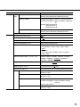
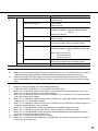
Setup items
H.264(1)
H.264(2)
Ch2 Ch4
Setting values (Underlined: default)
Unicast port1(Image) *21
1 024 - 50 000
(Default: [Ch2] 32006 [Ch3] 32008 [Ch4] 32010)
Multicast address
Available IPv4 address: 224.0.0.0 - 239.255.255.255
Available IPv6 address: Multicast address starting with
"FF"
(Default: [Ch2] 239.192.0.22
[Ch3] 239.192.0.24
[Ch4] 239.192.0.26)
Multicast port *21
1 024 - 50 000
(Default: [Ch2] 37006 [Ch3] 37008 [Ch4] 37010)
Multicast TTL/HOPLimit *23 *24
1 - 254 (Default: 16)
H.264 transmission *4 *5 *6
On/Off
Internet mode (over HTTP) *7 *8 *9 *10 *11
On/Off
Image capture size *25
QVGA/VGA
Transmission priority *12 *25
Constant bit rate/Frame rate
Frame rate *13 *14 *25
NTSC model:
1fps/3fps/5fps */7.5fps */10fps */15fps */20fps */
30fps *
PAL model:
1fps/3.1fps/4.2fps */6.25fps */8.3fps */12.5fps */
20fps */25fps *
Max bit rate (per client) * *15 *16 *17 *25
64kbps/128kbps */256kbps */384kbps */512kbps */
768kbps */1024kbps */1536kbps */2048kbps */
3072kbps */4096kbps */Unlimited *
Image quality *18 *25
Low(Motion priority)/Normal/Fine(Image quality priority)
Refresh interval *19 *25
0.2s/0.33s/0.5s/1s/2s/3s/4s/5s
Transmission type *20
Unicast port (AUTO)/Unicast port (MANUAL)/Multicast
Ch1
Unicast port1(Image) *21
1 024 - 50 000
(Default: 32 014)
Unicast port2(Audio) *21
1 024 - 50 000
(Default: 33 014)
Multicast address
Available IPv4 address: 224.0.0.0 - 239.255.255.255
Available IPv6 address: Multicast address starting
with "FF"
(Default: 239.192.0.21)
Multicast port *21 *22
1 024 - 50 000
(Default: 37 004)
35
Setup items
H.264(2)
Ch2 Ch4
Setting values (Underlined: default)
Unicast port1(Image) *21
1 024 - 50 000
(Default: [Ch2] 32016 [Ch3] 32018 [Ch4] 32020)
Multicast address
Available IPv4 address: 224.0.0.0 - 239.255.255.255
Available IPv6 address: Multicast address starting with
"FF"
(Default: [Ch2] 239.192.0.23
[Ch3] 239.192.0.25
[Ch4] 239.192.0.27)
Multicast port *21
1 024 - 50 000
(Default: [Ch2] 37006 [Ch3] 37008 [Ch4] 37010)
Multicast TTL/HOPLimit *23 *24
1 - 254 (Default: 16)
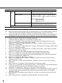
Important:
*23 • When two or more network interface cards are installed on the PC in use, the network interface card(s) not
used for receiving images should be invalidated when displaying images using the multicast port.
*24 • When transmitting an H.264 image via a network, the transmitted image sometimes may not be displayed
depending on the settings of a proxy server or a firewall. In this case, refer to the network administrator.
*1
*2
*3
*4
*5
*6
*7
*8
*9
*10
*11
*12
*13
*14
*15
*16
*17
*18
36
• When this setting is changed, the unit will reboot automatically.
• i-PRO Series does not support "D1", if not specified. (As of May, 2010)
• When "On" is selected for "H.264 transmission", the refresh interval may be longer than the set value
when any value with an asterisk (*) on the right is selected.
• When "On" is selected for "H.264 transmission" in "H.264(1)" or "H.264(2)", the transmission interval of
JPEG images may be longer.
• When "On" is selected for "H.264 transmission" in "H.264(1)", displaying of H.264 images or JPEG images
on the "Live" page will be available.
• When "On" is selected for "H.264 transmission" in "H.264(1)" and "H.264(2)", H.264 images are viewable
using other devices with each setting.
• When "On" is selected, H.264 images and audio will be transmitted using the HTTP port.
• When "On" is selected, only "Unicast port (AUTO)" will be available for "Transmission type".
• When "On" is selected, H.264 images may not be displayed depending on the number of the concurrent
access users and audio data availability, etc.
• When "On" is selected, only IPv4 access is available.
• When "On" is selected for either "H.264(1)" or "H.264(2)", the maximum concurrent access number is
equal to or less than 8 users.
• When "Frame rate" is set for "Transmission priority", number of users who can access the unit may be
decreased.
• When "Frame rate" is selected for "Transmission priority", this setting is available.
• "Frame rate" is synchronized with "Max bit rate (per client) *". For this reason, the frame rate may be lower
than the specified value when any value marked with an asterisk (*) is selected.
• "Unlimited *" is available when "Frame rate" is selected for "Transmission priority".
• The bit rate is synchronized with "Bandwidth control(bit rate)" on the [Network] tab of "Network" page. For
this reason, the bit rate may be lower than the value when any value with an asterisk (*) on the right is
selected. (☞ Page 54)
• When "Unlimited *" is selected for either "H.264(1)" or "H.264(2)", the maximum concurrent access number is 1 user.
• When "Constant bit rate" is selected for "Transmission priority", this setting is available.
*19
*20
*21
*22
*25
• Depending on the setting or photographic subject, images may not be refreshed at the exact designated
interval.
• When "Multicast" is selected, set the value of "Bandwidth control(bit rate)" on the [Network] tab of
"Network" page greater than the total value of "Max bit rate (per client) *" of all the channels in use.
(☞ Page 54)
• The following port numbers are unavailable since they are already in use.
10 669, 10 670
• When audio is transmitted from the unit, the port number to be used will be the multicast port number
plus "1 000".
• When "On" is selected for "H.264 transmission" of "H.264(1)", the setting values selected for "H.264(1)"
will be applied.
[JPEG/MPEG-4] tab
Refer to page 28 for general information about this tab.
Setup items
Setting values (Underlined: default)
Image capture mode *1 *2
VGA/D1
Ch selection *1
Ch1 only/Ch1-2/Ch1-3/Ch1-4
JPEG
Ch1 Ch4
Refresh interval (JPEG)* *3
NTSC model:
0.1fps/0.2fps/0.33fps/0.5fps/1fps/2fps/3fps */5fps */
6fps */10fps */15fps */30fps *
PAL model:
0.08fps/0.17fps/0.28fps/0.42fps/1fps/2.1fps/3.1fps */
4.2fps */5fps */8.3fps */12.5fps */25fps *
Image capture size
QVGA/VGA
Image quality
0 Super fine/1 Fine/2/3/4/5 Normal/6/7/8/9 Low
Video encoding format
H.264/MPEG-4
MPEG-4
(1)
MPEG-4 transmission *4 *5 *6
On/Off
Internet mode (over HTTP) *7 *8 *9 *10 *11
On/Off
Image capture size
QVGA/VGA
Transmission priority *12
Constant bit rate/Frame rate
Frame rate *13 *14
NTSC model:
1fps/3fps/5fps */7.5fps */10fps */15fps */20fps */
30fps *
PAL model:
1fps/3.1fps/4.2fps */6.25fps */8.3fps */12.5fps */
20fps */25fps *
Max bit rate (per client) * *15 *16 *17
64kbps/128kbps */256kbps */384kbps */512kbps */
768kbps */1024kbps */1536kbps */2048kbps */
3072kbps */4096kbps */Unlimited *
Image quality *18
Low(Motion priority) / Normal / Fine(Image quality priority)
Refresh interval *19
0.2s/0.33s/0.5s/1s/2s/3s/4s/5s
Transmission type *20
Unicast port (AUTO)/Unicast port (MANUAL)/Multicast
37
Setup items
MPEG-4
(1)
Ch1
Ch2 Ch4
MPEG-4
(2)
38
Setting values (Underlined: default)
Unicast port1(Image) *21
1 024 - 50 000
(Default: 32 004)
Unicast port2(Audio) *21
1 024 - 50 000
(Default: 33 004)
Multicast address
Available IPv4 address: 224.0.0.0 - 239.255.255.255
Available IPv6 address:Multicast address starting
with "FF"
(Default: 239.192.0.20)
Multicast port *21 *22
1 024 - 50 000
(Default: 37 004)
Unicast port1(Image) *21
1 024 - 50 000
(Default: [Ch2] 32006 [Ch3] 32008 [Ch4] 32010)
Multicast address
Available IPv4 address: 224.0.0.0 - 239.255.255.255
Available IPv6 address: Multicast address starting with
"FF"
(Default: [Ch2] 239.192.0.22
[Ch3] 239.192.0.24
[Ch4] 239.192.0.26)
Multicast port *21
1 024 - 50 000
(Default: [Ch2] 37006 [Ch3] 37008 [Ch4] 37010)
Multicast TTL/HOPLimit *23 *24
1 - 254 (Default: 16)
MPEG-4 transmission *4 *5 *6
On/Off
Internet mode (over HTTP) *7 *8 *9 *10 *11
On/Off
Image capture size *25
QVGA/VGA
Transmission priority *12 *25
Constant bit rate/Frame rate
Frame rate *13 *14 *25
NTSC model:
1fps/3fps/5fps */7.5fps */10fps */15fps */20fps */
30fps *
PAL model:
1fps/3.1fps/4.2fps */6.25fps */8.3fps */12.5fps*/
20fps */25fps *
Max bit rate (per client) * *15 *16 *17
64kbps/128kbps */256kbps */384kbps */512kbps */
768kbps */1024kbps */1536kbps */2048kbps */
3072kbps */4096kbps */Unlimited *
Image quality *18 *25
Low(Motion priority) / Normal / Fine(Image quality priority)
Refresh interval *19 *25
0.2s/0.33s/0.5s/1s/2s/3s/4s/5s
Transmission type *20
Unicast port (AUTO)/Unicast port (MANUAL)/Multicast
Setup items
MPEG-4
(2)
Ch1
Ch2 Ch4
Setting values (Underlined: default)
Unicast port1(Image) *21
1 024 - 50 000
(Default: 32 014)
Unicast port2(Audio) *21
1 024 - 50 000
(Default: 33 014)
Multicast address
Available IPv4 address: 224.0.0.0 - 239.255.255.255
Available IPv6 address: Multicast address starting
with "FF"
(Default: 239.192.0.21)
Multicast port *21 *22
1 024 - 50 000
(Default: 37 004)
Unicast port1(Image) *21
1 024 - 50 000
(Default: [Ch2] 32016 [Ch3] 32018 [Ch4] 32020)
Multicast address
Available IPv4 address: 224.0.0.0 - 239.255.255.255
Available IPv6 address: Multicast address starting with
"FF"
(Default: [Ch2] 239.192.0.23
[Ch3] 239.192.0.25
[Ch4] 239.192.0.27)
Multicast port *21
1 024 - 50 000
(Default: [Ch2] 37006 [Ch3] 37008 [Ch4] 37010)
Multicast TTL/HOPLimit *23 *24
1 - 254 (Default: 16)
Important:
*23 • When two or more network interface cards are installed on the PC in use, the network interface card(s) not
used for receiving images should be invalidated when displaying images using the multicast port.
*24 • When transmitting an MPEG-4 image via a network, the transmitted image sometimes may not be displayed depending on the settings of a proxy server or a firewall. In this case, refer to the network administrator.
*1
*2
*3
*4
*5
*6
*7
*8
*9
*10
*11
• When this setting is changed, the unit will reboot automatically.
• i-PRO Series does not support "D1", if not specified. (As of May, 2010)
• When "On" is selected for "MPEG-4 transmission", the refresh interval may be longer than the set value
when any value with an asterisk (*) on the right is selected.
• When "On" is selected for "MPEG-4 transmission" in "MPEG-4(1)" or "MPEG-4(2)", the transmission interval of JPEG images may be longer.
• When "On" is selected for "MPEG-4 transmission" in "MPEG-4(1)", displaying of MPEG-4 images or JPEG
images on the "Live" page will be available.
• When "On" is selected for "MPEG-4 transmission" in "MPEG-4(1)" and "MPEG-4(2)", MPEG-4 images are
viewable using other devices with each setting.
• When "On" is selected, MPEG-4 images and audio will be transmitted using the HTTP port.
• When "On" is selected, only "Unicast port (AUTO)" will be available for "Transmission type".
• When "On" is selected, MPEG-4 images may not be displayed depending on the number of the concurrent access users and audio data availability, etc.
• When "On" is selected, only IPv4 access is available.
• When "On" is selected for either "MPEG-4(1)" or "MPEG-4(2)", the maximum concurrent access number
is equal to or less than 8 users.
39
*12
*13
*14
*15
*16
*17
*18
*19
*20
*21
*22
*25
• When "Frame rate" is set for "Transmission priority", number of users who can access the unit may be
decreased.
• When "Frame rate" is selected for "Transmission priority", this setting is available.
• "Frame rate" is synchronized with "Max bit rate (per client) *". For this reason, the frame rate may be lower
than the specified value when any value marked with an asterisk (*) is selected.
• "Unlimited *" is available when "Frame rate" is selected for "Transmission priority".
• The bit rate is synchronized with "Bandwidth control(bit rate)" on the [Network] tab of "Network" page. For
this reason, the bit rate may be lower than the value when any value with an asterisk (*) on the right is
selected.
• When "Unlimited *" is selected for either "MPEG-4(1)" or "MPEG-4(2)", the maximum concurrent access
number is 1 user.
• When "Constant bit rate" is selected for "Transmission priority", this setting is available.
• Depending on the setting or photographic subject, images may not be refreshed at the exact designated
interval.
• When "Multicast" is selected, set the value of "Bandwidth control(bit rate)" on the [Network] tab of
"Network" page greater than the total value of "Max bit rate (per client) *" of all the channels in use.
• The following port numbers are unavailable since they are already in use.
10 669, 10 670
• When audio is transmitted from the unit, the port number to be used will be the multicast port number
plus "1 000".
• When "On" is selected for "MPEG-4 transmission" of "MPEG-4(1)", the setting values selected for
"MPEG-4(1)" will be applied.
[Image/Position] tab
Refer to page 28 for general information about this tab.
Setup items
Setting values (Underlined: default):
Ch No.
1/2/3/4
Menu
On/Off
Operation buttons
Set
Up
Down
Left
Right
Esc
Reset/Special
All Reset
Zoom
Zoom out/x1/Zoom in
Focus
Auto/Near/Far
Control pad
40
About the operation panel
Use the following buttons on the operation panel to operate the "Camera setup" page using a PC.
: Click this button to display the setup menu of
camera.
: Click this button to close the setup menu of
camera.
: Click this button to move to the submenu.
/
: Click these buttons to move the cursor.
/
eters.
: Click these buttons to select the param-
: Click this button to return to the previous page.
: Display the setup menu of camera,
move the cursor onto "SPECIAL", and click this button to move to the SPECIAL SETUP menu.
Move the cursor onto REFRESH on the SPECIAL
SETUP menu, and click this button to refresh the
camera position.
Item names and operations may differ depending on
the cameras. Refer to the operating instructions of
the camera for further information.
: Click this button after moving the cursor onto CAMERA RESET on the SPECIAL SETUP
menu to reset to the default setting. Refer to the
operating instructions of each camera for further
information about the settings to be reset.
[Audio] tab
Refer to page 28 for general information about this tab.
Setup items
Setting values (Underlined: default)
Audio transmission/reception *1 *2 *3 *4
Off/Mic input/Audio output/Interactive(Half-duplex)/
Interactive(Full-duplex)
Audio bit rate *5
16kbps/32kbps
Mic input volume (Camera to PC)
Mic High/Mic Middle/Mic Low/Line High/Line Middle/Line
Low
Mic Input Interval (Camera to PC) *6 *7
20ms/40ms/80ms/160ms
Audio output volume (PC to Camera)
High/Middle/Low
Audio output interval (PC to Camera) *6 *7 *8 *9
160ms/320ms/640ms/1280ms
Audio output port (PC to Camera) *10
1 024 - 50 000 (Default: 34 004)
Permission level of audio trans./recep.
1. Level 1 only/2. Level 2 or higher/3. All users
*1
*2
*3
• Images and audio will not be synchronized. Therefore, images and audio may not always match.
• Audio may be interrupted depending on the network environment.
• Howling may be generated depending on usage conditions. If howling is generated, prevent sound generated by the PC from entering the PC microphone.
41
*4
*5
*6
*7
*8
*9
*10
• When "Multicast" is selected for "Transmission type" on the [JPEG/H.264] (or [JPEG/MPEG-4]) tab of the
"Image/Audio" page, audio transmission will become unavailable while monitoring H.264 (or MPEG-4)
images. To transmit audio, click the [JPEG] button on the "Live" page.
• When selecting a smaller value for "Bandwidth control(bit rate)" on the [Network] tab of the "Network"
page (☞ page 54) while putting a priority on the JPEG/MPEG-4 image transmission, select "16kbps" for
"Audio bit rate".
• When a shorter interval is selected, delay time will be shorter.
• Making the value bigger will result in a longer delay, but audio interruptions can be minimized.
• Audio may temporarily be interrupted or noise may be heard the unit, or when multiple users are accessing concurrently. It may be possible to diminish the interruption or noise by setting a longer interval for
"Audio output interval (PC to Camera)".
• Audio may sometimes not be heard depending on the network environment.
• The transmission port number entered for "Audio output port (PC to Camera)" will be used only when
"Unicast port (MANUAL)" is selected for "Transmission type".
When "Off" is selected for "H.264 transmission" (or "MPEG-4 transmission") (☞ pages 34 and 37) or when
"Unicast (AUTO)" or "Multicast" is selected for "Transmission type", it is not necessary to enter the transmission port number.
[Coaxial/RS-485] tab
Refer to page 28 for general information about this tab.
Setup items
Coaxial
RS-485
Setting values (Underlined: default)
Video sync *1 *2
Ch1/Int
Ch1 - Ch4 VD2 *3
On/Off
Data *4
On/Off
Cable compensation *5 *6 *7
S/M/L
Communication protocol *8 *9 *10
4-line/2-line
Baud rate
2400bps/4800bps/9600bps/19200bps/38400bps
Data bit
7bit/8bit
Parity check
None/Odd/Even
Ch1 - Ch4 Data *11
On/Off
Unit address *12
(Default: [Ch1] 01 [Ch2] 02 [Ch3] 03 [Ch4] 04)
Important:
*1
*2
*5
42
• When "Ch1" is selected for "Video sync", the unit is synchronized with the video signal that is input to
Ch1. Synchronize other video signals that are input to other channels with Ch1.
• When "Ch1" is selected for "Video sync", the unit is synchronized with the phase of the video signal that
is input to Ch1. Synchronize the phases of other video signals that are input to other channels with Ch1.
• Perform the settings for the cable compensation properly according to the cable length. Otherwise camera pictures may not be displayed/recorded correctly.
*3
*4
*6
*7
*8
*9
*10
*11
*12
• Select "On" or "Off" to determine whether or not to apply the VD2 synchronization method for the connected camera. When a camera not supporting the VD2 synchronization method is connected, select
"Off" for "VD2".
• Select "On" to control cameras with the coaxial communication.
• It is possible to compensate for the video signal transmission loss from the camera.
• The following cable length settings are references when using RG-59/U, BELDEN 9259 (for NTSC models), 5C-2V (for PAL models) or equivalent cables.
S: Less than 400 m {1 300 ft.}
M: 400 m {1 300 ft.} to 700 m {2 300 ft.}
L: 700 m {2 300 ft.} to 1 200 m {4 000 ft.}
• When cameras with the different RS-485 protocols (for example, cameras manufactured by Panasonic
and those manufactured by Pelco, Inc.) in the same RS-485 communication line, the cameras will not
work correctly.
• Select the communication protocol that is compliant with the specifications of the connected cameras.
• Refer to the readme file on the provided CD-ROM for further information about the RS-485 command
table.
• Select "On" to control cameras with the RS-485 communication.
• Set the value in accordance with the RS-485 command table. Refer to the readme file on the provided
CD-ROM for further details.
43
[Multi-screen] page
[Multi-screen setup] tab
Refer to page 28 for general information about this tab. Refer to page 12 for how to operate.
Setup items
Group A
Group B
Group C
Group D
*1
*2
*3
*4
44
Setting values (Underlined: default)
Cam. 1 - Cam. 4
Cam. 5 - Cam. 8
Cam. 9 - Cam. 12
Cam. 13 - Cam. 16
IP address *1 *2
(Default: None (blank))
Ch No. *3
−/Ch1/Ch2/Ch3/Ch4
Camera title *4
(Default: None (blank))
IP address *1 *2
(Default: None (blank))
Ch No. *3
−/Ch1/Ch2/Ch3/Ch4
Camera title *4
(Default: None (blank))
IP address *1 *2
(Default: None (blank))
Ch No. *3
−/Ch1/Ch2/Ch3/Ch4
Camera title *4
(Default: None (blank))
IP address *1 *2
(Default: None (blank))
Ch No. *3
−/Ch1/Ch2/Ch3/Ch4
Camera title *4
(Default: None (blank))
• When using the host name, it is necessary to configure the DNS settings of the PC to be used for the
multi-screen display. (☞ Page 54)
• Regardless of the settings of the registered device, the images will be displayed altered to the aspect ratio
of 4:3 on a multi-screen.
• Select "–" when displaying images on a multi-screen using a device without channel information.
• When selecting a 16 split-screen, some characters of the camera title to be displayed may not be displayed.
[Alarm] page
[Alarm] tab
Refer to page 28 for general information about this tab. Refer to page 13 for further information about the actions.
Setup items
Alarm
Setting values (Underlined: default)
Ch1/Ch2/Ch3/Ch4
Terminal 1 *1 *2
Off/Alarm input
Ch1/Ch2/Ch3/Ch4
Terminal 2 *1 *2
Off/Alarm input/Alarm output
Ch1/Ch2/Ch3/Ch4
Terminal 3 *1 *2
Off/Alarm input/Alarm output/AUX output
VMD alarm
Command alarm
Command alarm *1
Ch1/Ch2/Ch3/Ch4
On/Off
Alarm image
Originating port number *3
1 - 65 535 (Default: 8 181)
Camera site alarm
Ch1 - Ch4
On/Off
Video loss
Ch1 - Ch4
On/Off
Alarm image FTP transmission *4 *5 *6
On/Off
Directory name
(Default: None (blank))
File name
(Default: None (blank))
Post alarm
Alarm output
terminal setup
AUX title
Transmission interval
*7
NTSC Model:
0.1fps/0.2fps/0.33fps/0.5fps/1fps
PAL Model:
0.08fps/0.17fps/0.28fps/0.42fps/1fps
Number of images
1pic/2pics/3pics/4pics/5pics/6pics/7pics/
8pics/9pics/10pics/20pics/30pics/50pics/
100pics/200pics/300pics/500pics/
1000pics/2000pics/3000pics
Recording duration *8
(Default: 100 sec.)
Image capture size
QVGA/VGA
Image compression rate upon alarm detection
On/Off
Image quality upon alarm detection
0 Super fine/1 Fine/2/3/4/5 Normal/6/7/8/
9 Low
Alarm output trigger
On/Off
Alarm output type
Latch/Pulse
Trigger output *9
Open/Close
Pulse width
1 - 120 sec. (Default: 1 sec.)
AUX (Up to 10 characters)
(Default: AUX)
Open (Up to 5 characters)
(Default: Open)
Close (Up to 5 characters)
(Default: Close)
45
Important:
*4
*7
*1
*2
*3
*5
*6
*8
*9
• When "Alarm input" or "Manual" is selected for "Save trigger" on the [SD memory card] tab, images will
not be transmitted to the FTP server even when an alarm is detected.
• Depending on the network line speed or the network traffic, images may not be transmitted at the exact
designated interval or period.
• "Alarm input", "Alarm output" and "Command alarm" are activated for the selected channel.
• Refer to the installation guide for further information about input/output rating of each terminal.
• The following port numbers are unavailable since they are already in use.
20, 21, 23, 25, 42, 53, 67, 68, 69, 80, 110, 123, 161, 162, 554, 995, 10 669, 10 670, 52 000,
59 000 - 61 000
• To transmit alarm images to an FTP server, it is necessary to configure the settings in advance. (☞ Page
52)
• When "D1" is selected for "Image capture mode", Alarm FTP image transmission is unavailable.
• The values (transmission interval x number of images) will automatically be set.
• When "Open" is selected, the alarm signal will be output for around 20 seconds when the power of the
unit is turned on.
[VMD area] tab
Refer to page 28 for general information about this tab.
Setup items
Setting values
(Underlined: default)
Ch No.
1/2/3/4
Area
VMD information addition
1 (White) / 2 (Blue) /
3 (Green) / 4 (Red)
Information addition *1 *2
Status
On/Off
Detection area
1 - 10 (Default: 1)
Detection sensitivity
1 - 15 (Default: 8)
On/Off
Important:
• The alarm occurrence indication button (☞ page 13) will be displayed when motion is detected by the VMD
function.
• The alarm occurrence indication button will be displayed when receiving an alarm input of a terminal alarm or a
command alarm.
• Depending on the network environment, notification may be delayed even when "Real time" is selected for
"Alarm status update mode" on the [Basic] tab of the "Basic" page (☞ page 30).
• The motion detection function is not the dedicated function to prevent thefts, fires, etc. We are not responsible
for any accidents or damages occurring in case.
• When "Multicast" is selected for "Transmission type" on the [JPEG/H.264] (☞ page 34) (or [JPEG/MPEG-4]
(☞ page 37)) tab or "On" is selected for "Priority stream" on the [System] tab, it may sometimes be impossible
to display the VMD area setup window.
46
*1
*2
• The VMD information can be searched by Panasonic network disk recorders (WJ-ND400 series). Refer to
the operating instructions of the connected devices for further information about the functions and settings.
• While a camera is during operation such as panning, tilting, zooming, focus adjustment, brightness adjustment or auto mode, the VMD information will be added.
The following is the procedure to set VMD areas
Important:
• When the settings are being configured on the setup menu, sometimes the VMD function may not work correctly.
Step1
Step 2
Set the video motion detection area by dragging the
mouse on the screen.
→ The designated area will become the VMD area and
the outline will be displayed. When 2 - 4 VMD areas
are set, each area will be numbered in order. The
areas will be identified by the respective outline colors. The "Status" of the outline to be set for the area
will become "Valid".
Adjust "Detection area" and "Detection sensitivity"
using the slide bar. The currently displayed area and its
detection sensitivity will be displayed in the "Detection
area" section. Change areas and the settings of
"Detection area" and "Detection sensitivity" as necessary.
Step 3
Click the [Set] button after completing the settings.
Important:
• The setting will not be applied unless the [Set] button is clicked.
Step 4
To invalidate the VMD area, click the [Set] button after
selecting "Off" for "Status" of the VMD area to be invalidated.
→ The outline of the invalidated VMD area will turn to a
dotted line. When the VMD area is invalidated, no
alarm will occur even when a motion can be recognized in the area.
Step 5
To delete the VMD area, click the [Delete] button corresponding to the area to be deleted.
→ The outline of the respective VMD area will disappear.
Step 6
Click the [Set] button.
→ The edited settings will be applied.
47
[Notification] tab
Refer to page 28 for general information about this tab.
Setup items
Setting values
(Underlined: default)
Mail notification
Mail notification
Destination of notification
Address1 - 4
Panasonic alarm protocol
notification
Destination of notification
*6
On/Off
Alarm *1
On/Off
Diag. *2
On/Off
Destination address
(Default: None (blank))
Mail subject
(Default: None (blank))
Mail body *3
(Default: None (blank))
Panasonic alarm protocol *4
On/Off
Destination port *5
1 - 65 535 (Default: 1 818)
Retry times
0 - 30 (Default: 2)
Address1 - 3
Alarm *7
On/Off
Diag. *8
On/Off
Destination IP address
(Default: None (blank))
Important:
*6
• When a device does not exist on the registered IP address, notification may be delayed.
*1
*2
*3
*4
*5
*7
*8
48
• The mail notification will be performed upon an alarm occurrence.
• Mail notification will be provided in the following cases.
• When it is configured to notify users of available capacity of the SD memory card
• When the capacity of the SD memory card has become insufficient
• When the SD memory card has failed to mount
• When the video loss is recovered
• Notification mail will be sent with the following message. (The message to be sent differs depending on
the status of the SD memory card.)
• "The SD memory card is full." (This message will be sent when the SD memory card becomes full.)
• "The SD memory card cannot be recognized." (This message will be sent when the SD memory card
has failed to mount.)
• When "On" is selected, notification of the alarm occurrence will be provided to the registered destination
addresses in order (to IP address 1 first, to IP address 3 last).
• The following port numbers are unavailable since they are already in use.
20, 21, 23, 25, 42, 53, 67, 68, 69, 80, 110, 123, 161, 162, 995, 10 669, 10 670
• The Panasonic alarm notification will be provided upon an alarm occurrence.
• Maintenance requirement will be notified in the following cases.
• When it is configured to notify users of available capacity of the SD memory card
• When the capacity of the SD memory card has become insufficient
• When the SD memory card has failed to mount
• When the video loss is recovered
[Advanced func.] page
[XML notification] tab
Refer to page 28 for general information about this tab.
Setup items
XML notification *1
Destination setting for
XML notification
*1
*2
*3
Setting values
(Underlined: default)
XML notification *2
On/Off
Notification interval
1s/2s
Destination1 - 2
Destination address
(Default: None (blank))
Destination port number *3
1 - 65535
(Default: None (blank))
Destination path name
(Default: None (blank))
User name
(Default: None (blank))
Password
(Default: None (blank))
• When "D1" is selected for "Image capture mode", it is impossible to activate the XML notification function.
• When "On" is selected, face detection information is notified to the designated destination server in the
XML format.
• The following port numbers are unavailable since they are already in use.
20, 21, 23, 25, 42, 53, 67, 68, 69, 110, 123, 161, 162, 995, 10 669, 10 670
[Face detection] tab
Refer to page 28 for general information about this tab.
Setup items
Face detection
Setting values (Underlined: default)
Face detection *1 *2 *3 *4
On/Off
XML notification
Important:
• When "Multicast" is selected for "Transmission type" on the [JPEG/H.264] (or [JPEG/MPEG-4]) tab and "On" is
selected for "Priority stream" on the [System] tab, it may sometimes be impossible to display the face detection
setup window.
*1
• The face detection function shall not guarantee the detection of faces in an image. The face detection
accuracy varies with imaging conditions.
*2
• When "Mosaic" is selected for "Display type" of "Privacy zone", the face detection function may sometimes be triggered (the face detection frame will be displayed).
*3
*4
• When "D1" is selected for "Image capture mode", it is impossible to activate the face detection function.
• Face detection is available on Ch1 only.
49
[User mng.] page
[User auth.] tab
Refer to page 29 for general information about this tab.
Setup items
Setting values (Underlined: default)
User auth. *1
On/Off
User name
(Default: None (blank))
Password *2
(Default: None (blank))
Retype password
(Default: None (blank))
Access level *3
1. Administrator/2. Camera control/3. Live only
User check *4
(Example: admin [1])
*1
*2
*3
*4
• When user authentication (authentication error) has failed to pass 8 times within 30 seconds using the
same IP address (PC), access to the unit will be denied for a while.
• When the user name already in use is entered and the [Register] button is clicked, the respective user
information will be overwritten.
• 1. Administrator: Allowed all available operations of the unit.
2. Camera control: Allowed to display images from the camera and to control the camera. The unit setting
configuration is unavailable.
3. Live only: Only displaying live images is available. The unit setting configuration and camera control are
unavailable.
• The registered users will be displayed in the drop-down list as follows: "User name [access level]"
[Host auth.] tab
Refer to page 29 for general information about this tab.
Setup items
Setting values (Underlined: default)
Host auth.
On/Off
IP address *1 *2
(Default: None (blank))
Access level
1. Administrator/2. Camera control/3. Live only
Host check *3
*1
*2
*3
50
• When "IP address/subnet mask" is entered, it is possible to restrict PCs in each subnet.
For example, when "192.168.0.1/24" is entered and "2. Camera control" is selected for the access level,
the PCs whose IP address is between "192.168.0.0" - "192.168.0.255" can access the unit with the
access level "2. Camera control".
• When the IP address already in use is entered and the [Set] button is clicked, the respective host information will be overwritten.
• The registered hosts will be displayed in the drop-down list as follows: "Host name [access level]"
(Example: 192.168.0.21 [1])
[System] tab
Refer to page 29 for general information about this tab.
Setup items
Priority stream
*1
*2
*3
Setting values (Underlined: default)
Activation *1
On/Off
Destination IP address(1) - (4)
(Default: None (blank))
Stream type
JPEG
H.264/MPEG-4(1)
H.264/MPEG-4(2)
Refresh interval* *2 *3
NTSC model:
0.1fps/0.2fps/0.33fps/0.5fps/1fps/2fps/3fps */
5fps */6fps */10fps */15fps */ 30fps *
PAL model:
0.08fps/0.17fps/0.28fps/0.42fps/1fps/2.1fps/
3.1fps */4.2fps */ 5fps */8.3fps */12.5fps */
25fps *
Image capture size *3
QVGA/VGA
• When "On" is selected for "Activation" of "Priority stream", number of users who can access the unit may
be limited.
• When "On" is selected for "H.264 transmission" (or "MPEG-4 transmission") or "Ch1 only" is not selected
for "Ch selection", the refresh interval may be longer than the set value when any value with an asterisk (*)
on the right is selected.
• This setting is validated only when "JPEG" is selected for "Stream type".
51
[Server] page
[Mail] tab
Refer to page 29 for general information about this tab.
Setup items
Setting values (Underlined: default)
SMTP server address *1
(Default: None (blank))
SMTP port *2
1 - 65535 (Default: 25)
POP server address *1
(Default: None (blank))
Authentication
Type *3
None/POP before SMTP/SMTP
User name
(Default: None (blank))
Password
(Default: None (blank))
Sender's mail address
(Default: None (blank))
Important:
• When a terminal that receives e-mails is not compatible with UTF-8 encode, it is impossible to receive alarm
mails correctly.
*1
• When entering the host name for "SMTP server address" or "POP server address", it is necessary to configure the DNS settings on the [Network] tab of the "Network" page. (☞ Page 54)
*2
*3
• The following port numbers are unavailable since they are already in use.
20, 21, 23, 42, 53, 67, 68, 69, 80, 110, 123, 161, 162, 995, 10 669, 10 670
• When you don't know the authentication method to send e-mails, refer to the network administrator.
[FTP] tab
Refer to page 29 for general information about this tab.
Setup items
Setting values (Underlined: default)
FTP server address *1
(Default: None (blank))
User name
(Default: None (blank))
Password
(Default: None (blank))
Control port *2
1 - 65535 (Default: 21)
FTP mode
Passive/Active
Important:
*1
• When entering the host name for "FTP server address", it is necessary to configure the DNS settings on
the [Network] tab of the "Network" page. (☞ Page 54)
*2
• The following port numbers are unavailable since they are already in use.
20, 23, 25, 42, 53, 67, 68, 69, 80, 110, 123, 161, 162, 995, 10 669, 10 670
52
[NTP] tab
Refer to page 29 for general information about this tab.
Setup items
Setting values (Underlined: default)
Time adjustment *1
Manual/Synchronization with NTP server
NTP server address *2
(Default: None (blank))
NTP port *3
1 - 65535 (Default: 123)
Time adjustment interval
1h - 24h
Time zone
(Default: (GMT) Greenwich Mean Time : Dublin,
Edinburgh, Lisbon, London)
Important:
*2
• Use an NTP server when the more accurate time & date setting is required for the system operation.
• When entering the host name for "NTP server address", it is necessary to configure the DNS settings on
the [Network] tab of the "Network" page. (☞ Page 54)
*1
*3
• When "Manual" is selected, the time set on the [Basic] tab on the "Basic" page will be used as the standard time of the unit. (☞ Page 30)
• The following port numbers are unavailable since they are already in use.
20, 21, 23, 25, 42, 53, 67, 68, 69, 80, 110, 161, 162, 995, 10 669, 10 670
53
[Network] page
[Network] tab
Refer to page 29 for general information about this tab.
Setup items
On/Off
IP address(IPv4) *2
(Default: 192.168.0.10)
Subnet mask
(Default: 255.255.255.0)
Default gateway *3
(Default: 192.168.0.1)
IPv6 network
Manual
On/Off
IP address(IPv6) *4
(Default: None (blank))
Common
DNS *5 *6
Auto/Manual
Primary server address *7
(Default: None (blank))
Secondary server address *7
(Default: None (blank))
HTTP port *8
1 - 65 535 (Default: 80)
Line speed *9
Auto/100M-Full/100M-Half/10M-Full/10M-Half
FTP access to unit
Allow/Forbid
Bandwidth control(bit rate) *10 *11 *12
Unlimited/64kbps/128kbps/256kbps/384kbps/512kbps/
768kbps/1024kbps/2048kbps/4096kbps/8192kbps
Easy IP Setup accommodate period
20 min/Unlimited
*1
*2
*3
*4
*5
*6
*7
*8
*9
*10
*11
54
Setting values (Underlined: default)
DHCP *1
IPv4 network
• Configure the DHCP server not to assign the same IP addresses used for the other network devices and
PCs whose IP address is unique. Refer to the network administrator for further information about the settings of the server.
• Do not enter an IP address already in use (for the PCs and the other network devices).
• Multiple IP addresses for the default gateway are unavailable even when using the DHCP function. Refer
to the network administrator for further information about the settings of the DHCP server.
• To establish connections beyond the router via an IP address entered manually, use an IPv6 compatible
router, and activate the auto configuration function of IP address. In addition, set an IPv6 address including prefix information given by the IPv6 compatible router.
• Multiple IP addresses for the default gateway are unavailable even when using the DHCP function. Refer
to the network administrator for further information about the settings of the DHCP server.
• When using the DHCP function, it is possible to obtain the DNS address automatically by selecting
"Auto". Refer to the network administrator for further information about the settings of the DHCP server.
• It is impossible to use both an IPv4 DNS server and an IPv6 DNS server.
• The following port numbers are unavailable since they are already in use.
20, 21, 23, 25, 42, 53, 67, 68, 69, 110, 123, 161, 162, 554, 995, 10 669, 10 670, 52 000, 59 000 - 61 000
• It is recommended to use with the default "Auto".
• When selecting "64kbps", select "Off" for "Audio mode" on the [Audio] tab. (☞ Page 41)
• Select "128kbps" or a faster rate to carry out the live transmission of JPEG images and the FTP periodic
image transmission simultaneously.
*12
• When "Bandwidth control(bit rate)" on the [Network] tab of the "Network" page is set low, taking a picture
using the one shot button may not function depending on the use environment. In this case, select
"QVGA" for "Image capture size" of "JPEG" on the [JPEG/H.264] (☞ page 34) (or [JPEG/MPEG-4]
(☞ page 37)) tab or set "Image quality" of "JPEG" lower.
Note:
• Refer to the network administrator for the addresses of each server.
• The port forwarding function changes a global IP address to a private IP address, and "Static IP masquerade"
and "Network Address Translation (NAT)" have this function.This function is to be set in a router.
• To access this unit via the Internet by connecting the unit to a router, it is necessary to assign a respective HTTP
port number for each device and address translation by using the port forwarding function of the router. Refer to
the operating instructions of the decoder for further information.
Enter [Global IP address + :
(colon) + port number] in the
"Address" box of the browser
via the Internet.
vvv.xxx.yyy.zzz:82
vvv.xxx.yyy.zzz:81
Internet
(WAN)
WAN
Global address
vvv.xxx.yyy.zzz
Router
LAN
Private address
192.168.0.254
Address translation using the port
forwarding function
vvv.xxx.yyy.zzz:82 → 192.168.0.2:82
Cable modem
xDSL modem
Private address
192.168.0.2
Port number: 82
OPERATE
ACT
SD CARD
ERROR
LINK
Network
Video Enco
der
WJ-GXE50
0
Address translation using the port
forwarding function
vvv.xxx.yyy.zzz:81 → 192.168.0.1:81
Private address
192.168.0.1
Port number: 81
OPERATE
ACT
SD CARD
ERROR
LINK
Network
Video Enco
der
WJ-GXE50
0
[DDNS] tab
Refer to page 29 for general information about this tab.
Setup items
Setting values (Underlined: default)
DDNS
On/Off
Host name
(Default: None (blank))
User name
(Default: None (blank))
Password
(Default: None (blank))
Access interval
1min/10min/30min/1h/6h/24h
• When communicating using IPv4, obtain a global IP address from the DHCP server. To access this unit via the
Internet, it is necessary to configure the settings for the DDNS function. When using the DDNS function, it is
possible to access with "Host name registered in the DDNS server.nmdns.net". To use the DDNS function, it is
necessary to connect to the dedicated DDNS server. Refer to the web site for further information about the
DDNS. Refer to the readme file on the provided CD-ROM for the web site.
55
[SNMP] tab
Refer to page 29 for general information about this tab.
Setup items
Setting values (Underlined: default)
Community *1
(Default: None (blank))
System name
(Default: None (blank))
Location
(Default: None (blank))
Contact
(Default: None (blank))
Important:
*1
• When using the SNMP function, it is necessary to enter the community name. When no community name
is entered, the SNMP function will not work.
[FTP img. trans.] tab
Refer to page 29 for general information about this tab. Refer to page 15 for further information about the actions.
Setup items
FTP periodic
image transmission
Setting values (Underlined: default)
FTP periodic image transmission *1 *2
On/Off
Directory name
(Default: None (blank))
File name
(Default: None (blank))
Name w/time&date / Name w/o
time&date
FTP image
transmission
schedule
Transmission interval *3 *4 *5
1s/2s/3s/4s/5s/6s/10s/15s/20s/30s/
1min/2min/3min/4min/5min/6min/
10min/15min/20min/30min/1h/1.5h/2h/
3h/4h/6h/12h/24h
Image capture size
QVGA/VGA
Schedule 1 - 3
Mon/Tue/Wed/Thu/Fri/Sat/Sun
On/Off
24h
On/Off
Hour (start)
00 - 23 (hour) (Default: 00)
Minute (start)
00 - 59 (minute) (Default: 00)
Hour (stop)
00 - 23 (hour) (Default: 00)
Minute (stop)
00 - 59 (minute) (Default: 00)
Important:
*1
• When "Alarm input" or "Manual" is selected for "Save trigger" on the [SD memory card] tab, the FTP periodic image transmission function will become unavailable. (☞ Page 31)
*2
• When "D1" is selected for "Image capture mode", FTP periodic image transmission is unavailable.
*3
• Depending on the network line speed or the network traffic, images may not be transmitted at the exact
designated interval or period.
*4
• When "On" is selected for both of the alarm image transmission function and the FTP periodic image
transmission function, the alarm image transmission function will be given priority over the FTP periodic
image transmission function. For this reason, images may not be transmitted at the exact designated
interval or period if alarms occur frequently.
56
*5
• Depending on the use environment, images may not be transmitted at the exact designated interval.
[Schedule] page
[Schedule] tab
Refer to page 29 for general information about this tab.
Setup items
Schedules
*1
*2
*3
*4
Setting values (Underlined: default)
Schedule1 - 5
Schedule mode *1 *2 *3 *4
Off/Alarm permission/VMD permission/
Access permission
Mon/Tue/Wed/Thu/Fri/Sat/Sun
On/Off
24h
On/Off
Hour (start)
00 - 23 (hour) (Default: 00)
Minute (start)
00 - 59 (minute) (Default: 00)
Hour (stop)
00 - 23 (hour) (Default: 00)
Minute (stop)
00 - 59 (minute) (Default: 00)
• Alarm permission: Alarm input (terminal alarm 1, 2 and 3) will be received during the period of the schedule.
• VMD permission: The video motion detection (VMD) function will be active during the period of the schedule.
• Access permission: Users whose access level is set to 2 and 3 on the [User auth.] tab of "User mng."
page can access the unit only in the period of schedule.
• Select "On" for "User auth." on the [User auth.] tab of "User mng." page (☞ page 50) and "Off" for "Host
auth." on the [Host auth.] tab of "User mng." page (☞ page 50) to validate "Access permission".
57
About the displayed system log
Refer to page 21 for how to check the system log.
Error indications relating to SMTP
Category
POP3 server error
SMTP server error
Internal error
Indication
Authentication error.
Description
• Entered user name or password may be
incorrect. Check if the mail settings are
configured correctly.
Failed to find the POP3 server.
• The IP address of the server may be
incorrect. Check if the IP address of the
server is configured correctly.
• The POP3 server may be down. Ask the
network administrator.
Authentication error.
• Entered user name or password may be
incorrect. Check if the mail settings are
configured correctly.
Failed to resolve the mail server address
from DNS.
• The designated IP address of the DNS
may be incorrect. Check if the DNS settings are configured correctly.
• The DNS server may be down. Ask the
network administrator.
Failed to find the SMTP server.
• The IP address of the server may be
incorrect. Check if the IP address of the
server is configured correctly.
• The SMTP server may be down. Ask the
network administrator.
Undefined error.
• An error occurred in the mail function.
Check if the mail settings are configured
correctly.
Error indications relating to FTP
Category
FTP server error
Connection error
Indication
Failed to resolve the FTP server address
from DNS.
Description
• The FTP server may be down. Ask the
network administrator.
Failed to find the FTP server.
• The IP address of the server may be
incorrect. Check if the IP address of the
server is configured correctly.
File transfer error.
• The FTP server settings may be incorrect. Check if the FTP settings are configured correctly.
• The settings relating to the indicated item
may be incorrect. Check if the FTP settings are configured correctly.
Passive mode error.
Log out failed.
Failed to change the directory.
User name or password isn't correct.
Internal error
58
Undefined error.
• An error occurred in the FTP function.
Check if the FTP settings are configured
correctly.
Error indications relating to DDNS
Category
Connection error
Internal error
Indication
No response from the DDNS server.
Description
• The designated IP address of the DDNS
may be incorrect. Check if the DDNS settings are configured correctly.
• The DDNS server may be down. Ask the
network administrator.
User name or password isn't correct.
• Entered user name or password may be
incorrect. Check if the DDNS settings are
configured correctly.
IP address update failed.
• IP address update error occurred in the
DDNS server. Ask the network administrator.
Undefined error.
• An error occurred in the DDNS function.
Check if the DDNS settings are configured correctly.
Error indications relating to NTP
Category
Connection error
Indication
No response from the NTP server.
Description
• The IP address of the server may be
incorrect. Check if the IP address of the
server is configured correctly.
• The NTP server may be down. Ask the
network administrator.
Internal error
Undefined error.
• An error occurred in the NTP function.
Check if the NTP settings are configured
correctly.
Synchronizing with
NTP succeeded.
NTP update succeeded.
• Time correction succeeded.
Error indications relating to login
Category
Login
Indication
User name or IP address
Description
• The login user name will be displayed
when "On" is selected for "User auth.".
• The IP address of the PC currently
accessing to the unit will be displayed
when "On" is selected for "Host auth.".
59
Troubleshooting
Before asking for repairs, check the symptoms with the following table.
Contact your dealer if a problem cannot be solved even after checking and trying the solution in the table or a problem is not described below.
Symptom
Cause/solution
Reference
pages
• Is the LAN cable (category 5 or better) firmly connected to the network connector of the unit?
Installation
Guide
• Is the link LED lit?
When it is not lit, connection to a LAN may not be
established or a network may be not working correctly.
Check if the cables have any contact failure or if the
wiring is correct or not.
Installation
Guide
• Is the power of the unit on?
Check if the power of the unit is turned on.
Installation
Guide
• Are the set IP addresses valid?
Cannot access from the
web browser.
60
• Are you accessing the wrong IP address?
Check the connection as follows
With the Windows command prompt,
> ping "IP address of the unit"
If there is reply from the unit, the connection is normal.
If not, proceed either of the following.
• Reboot the unit and change the IP address by
using the Panasonic IP setup software within 20
minutes after the restart.
• Reboot the unit while holding the [INITIAL SET]
button on the unit. The unit will be initialized and
the IP address will return to the default setting
"192.168.0.10".
After the unit is initialized, access the unit and set
the IP address again. (When the unit is initialized,
all the settings of the unit previously configured on
the setup menus will be initialized.)
54
54
Installation
Guide
Symptom
Cannot access from the
web browser.
Cannot obtain images on
the SD memory card.
No image is displayed.
Cause/solution
Reference
pages
• Is the same IP address provided to other devices?
Are there contradictions between the address and the
network subnet to be accessed?
<When the unit and the PC are connected in the same
subnet>
Are the IP addresses of the unit and the PC set in a
common subnet? Or is "Use Proxy Server" for the settings of the web browser checked?
When accessing the unit in the same subnet, it is recommended to enter the address of the unit in the
"Don’t Use Proxy For These Addresses" box.
<When the unit and the PC are connected in the different subnet>
Is the IP address of the default gateway set for the unit
correct?
–
• Is "Allow" selected for "FTP access to unit" on the
[Network] tab of "Network" page?
It is necessary in advance to select "Allow" for "FTP
access to unit" on the [Network] tab of the "Network"
page.
54
• Is the entered password correct?
Restart the web browser and enter the password
again.
50
• Access to the SD memory card may be failed. Restart
the browser and retry to obtain images.
–
• Is the viewer software installed on the PC?
Install the viewer software on a PC.
4
• Is the version of DirectX 9.0c or later?
Check the version of DirectX as follows.
(1) Select "Run…" from the start menu of Windows.
(2) Enter "dxdiag" in the displayed dialog box and
click the [OK] button.
If the version of DirectX is older than 9.0c, upgrade it.
–
61
Cause/solution
Reference
pages
• When "Every time I visit the webpage" is not selected
for "Check for newer versions of stored pages:" in the
"Temporary Internet Files" section, images sometimes
may not be displayed on the "Live" page.
In this case, do the following.
(1) Select "Internet Options…" from "Tools" on the
menu bar of Internet Explorer. The "Internet
Options" window will be displayed.
(2) When using Internet Explorer 8.0 or Internet
Explorer 7.0
Click the [Settings] button in the "Browsing history" section on the [General] tab, and then select
"Every time I visit the webpage" for "Check for
newer versions of stored pages:" in the
"Temporary Internet Files" section on the
"Temporary Internet Files and History Settings"
window.
When using Internet Explorer 6.0
Click the [Settings…] button in the "Temporary
Internet files" section on the [General] tab, and
then select "Every visit to the page" for "Check for
newer versions of stored pages:" on the "Settings"
window.
–
• Depending on the version of your browser, there might
be difficulties refreshing the picture, etc.
Installation
Guide
• Depending on the traffic of the network or the concentration of access to the unit, there might be difficulties
displaying the camera picture. Request the camera
picture using the browser such as by pressing the [F5]
key, etc.
–
No image is displayed (or
too dark).
• Is the brightness setting set at an appropriate level?
Click the [Normal] button of [Brightness].
9
Images are displayed
washed out.
• Is the brightness setting set at an appropriate level?
Click the [Normal] button of [Brightness].
9
Changed settings are not
saved.
• Was the power of the unit turned off soon after the
settings had been changed?
Wait for around 10 seconds or more when turning off
the power of the unit after the setting change.
–
Symptom
No image is displayed on
the "Live" page.
The image is not being
refreshed.
62
Symptom
Cause/solution
• Is the SD memory card inserted correctly?
Check if the SD memory card is inserted correctly.
Images cannot be saved on
the SD memory card.
Cannot transmit audio to the
unit.
Reference
pages
Installation
Guide
• Is the SD memory card formatted?
Format the SD memory card.
31
• Isn’t the write protect switch set to "LOCK"?
When the write protect switch is set to "LOCK", available size/total size indication of the SD memory card
to be displayed on the [SD memory card] tab will be
"**********KB/**********KB".
31
• Isn't the SD memory card out of order?
There are limited times to overwrite on an SD memory
card. When frequently overwritten, it may be at the
end of product life. It is recommended to replace the
SD memory card.
–
• Are the microphone and the speaker connected correctly and firmly?
Confirm that they are connected correctly and firmly.
Installation
Guide
• Is the viewer software installed on the PC?
Confirm that the viewer software "Network Camera
View 4" is installed.
4
The alarm occurrence indication button, the [AUX] buttons and the SD recording
status indicator on the "Live"
page do not display the current status in real time.
• Is the viewer software installed on the PC?
Confirm that the viewer software "Network Camera
View 4" is installed.
4
• Is "Real time" selected for "Alarm status update
mode"?
30
No image is displayed on the
"Live" page.
• Press the [F5] key on the keyboard of the PC or click
the [Live] button.
7
Cannot download the log
list.
• Download of files using Internet Explorer may be disabled.
Click "Internet Options" on the Tool menu of Internet
Explorer, and [Security] tab. Then, click the [Custom
Level…] button to open the "Security Setting" window. Under "Download", select "Enable" for
"Automatic prompting for file downloads". Click the
[OK] button. The "Warning" window will be displayed.
Click the [Yes] button.
–
63
Symptom
Images are not displayed or
not refreshed smoothly.
64
Cause/solution
Reference
pages
• Delete temporary internet files as follows.
(1) Select "Internet Options…" under "Tools" on the
menu bar of Internet Explorer. The "Internet
Options" window will be displayed.
(2) Click the [Delete Files…] button in the "Temporary
Internet files" section on the [General] tab.
–
• The firewall function of the anti-virus software may be
filtering the port of the unit.
Exclude the port number of the unit from the list of the
port numbers to be filtered by the anti-virus software.
–
SDHC/SD memory card
error indicator does not
light.
• Is "Off" selected for "SD memory card error LED" on
the "Basic" page?
Select "On" for "SD memory card error LED".
30
H.264 (or MPEG-4) images
are not displayed.
• When "Network Camera View 4" is deleted from a PC
on which both the viewer software "Network Camera
View 3" and "Network Camera View 4" are installed,
H.264 (or MPEG-4) images may not be displayed.
In this case, delete "Network Camera View 3" from
the PC and then install "Network Camera View 4".
4
Symptom
When displaying H.264 (or
MPEG-4) images on two or
more web browser windows, images from two or
more cameras are displayed
in sequence on a single
browser window.
Cause/solution
Reference
pages
• This may occur due to the display adapter and driver
combination.
When this has occurred, first update the driver of the
display adapter to the latest version.
If updating the driver does not solve the problem,
adjust the hardware acceleration as follows.
The following are descriptions for when Windows XP
is installed on the PC in use.
(1) Right-click on the desktop and select "Properties"
from the displayed pop-up menu.
(2) Select "Settings" from "Display Properties", and
then click the [Advanced] button.
(3) Click the [Troubleshoot] tab and disable the
DirectDraw acceleration by adjusting the level of
"Hardware acceleration".
–
65
Depending on the OS installed on the PC, the following may occur.
Follow the instructions below when the following has occurred. By performing the following solutions, other applications and the security level may not be affected.
The "Information Bar" expressed in the following symptom and solutions will be displayed just below the address
bar only when there is information to communicate.
Information Bar
Symptom
The following message is displayed on the information bar.
"Pop-up blocked. To see this
pop-up or additional options,
click here…"
• Click the information bar and select "Always Allow
Pop-ups from This Site…". The dialog window saying "Allow pop-ups from this site?" will be displayed.
Click the [Yes] button.
The following message is displayed on the information bar.
"This site might require the
following ActiveX control
'nwcv4setup.exe' from
'Panasonic System Networks
Co., Ltd.'. Click here to
install..."
"Pop-up blocked. To see this
pop-up or additional options,
click here…"
• Click the information bar and select "Install ActiveX
Control".
The "Security Warning" window will be displayed.
Click the "Install" button on the displayed "Security
Warning" window.
An unnecessary status bar or
scroll bar is displayed on the
pop-up window.
66
Cause/solution
Reference
pages
–
–
• Click "Internet Options…" under "Tools" of the menu
bar of Internet Explorer, and then click the [Security]
tab. Click "Internet" in the "Select a Web content
zone to specify its security settings:" section. Then,
click the [Custom Level…] button to open the
"Security Setting" window. Under "Miscellaneous",
select "Enable" for "Allow script-initiated windows
without size or position constraints". Click the [OK]
button.
When the warning window is displayed, click the
[Yes] button.
–
Symptom
Cause/solution
Reference
pages
Images are not fit in the
frames.
• When "120 DPI" is not selected for "DPI setting",
they may not be displayed correctly.
Click the [Settings] tab on the "Properties" window
of "Screen" (in the control panel), and then click the
[Advanced] button. Change the "DPI setting" to
"Large size (120 DPI)".
–
Displayed images are distorted.
• Images may be distorted when non-interlace signals, VCR (VTR) signals or signals not compliant
with the standard in your locality are transmitted.
–
Black lines appear on the
screen.
• Black lines may appear on the images displayed on
the screen when transmitting the VD2 synchronization signals to cameras not supporting the VD2 synchronization. Deactivate the VD2 synchronization.
42
Black bars are displayed on
both edges of the screen.
• When the image capture mode is D1, due to the
standard of video signal, black bars appear instead
of images on both edges of the screen. Black bar(s)
also appear(s) even in the VGA mode when signals
not compliant with the standard in your locality are
transmitted.
–
A picture is sometimes output
twice or skipped.
• Such a phenomenon occurs when the video frequency of a camera and that of the unit are not fully
synchronized.
When using cameras supporting the VD2 synchronization:
Select "Int" for "Video sync", and then select
"On" for "VD2".
When using cameras not supporting the VD2
synchronization:
Select "Ch1" for "Video sync".
With this setting, the unit operates synchronized
with the video frequency of the camera that supplies the input signal to Ch1.
42
67
Appendix
Possible number of images that can be saved on the SD memory card (as indications)
Important:
• The numbers on the following table are just indications. They are not actual numbers of images that can be
saved on the SD memory card. Numbers will differ according to photographic subject to the SD memory card.
Image capture size: VGA
Capacity of SD/
SDHC memory
card
32 GB
16 GB
8 GB
4 GB
2 GB
1 GB
512 MB
256 MB
Capacity of SD/
SDHC memory
card
32 GB
16 GB
8 GB
4 GB
2 GB
1 GB
512 MB
256 MB
Image quality
0(Super fine)
160 000 pics
80 000 pics
40 000 pics
20 000 pics
10 000 pics
5 000 pics
2 500 pics
1 250 pics
1(Fine)
224 000 pics
112 000 pics
56 000 pics
28 000 pics
14 000 pics
7 000 pics
3 500 pics
1 750 pics
2
256 000 pics
128 000 pics
64 000 pics
32 000 pics
16 000 pics
8 000 pics
4 000 pics
2 000 pics
3
288 000 pics
144 000 pics
72 000 pics
36 000 pics
18 000 pics
9 000 pics
4 500 pics
2 250 pics
4
320 000 pics
160 000 pics
80 000 pics
40 000 pics
20 000 pics
10 000 pics
5 000 pics
2 500 pics
Image quality
5(Normal)
352 000 pics
176 000 pics
88 000 pics
44 000 pics
22 000 pics
11 000 pics
5 500 pics
2 750 pics
6
416 000 pics
208 000 pics
104 000 pics
52 000 pics
26 000 pics
13 000 pics
6 500 pics
3 250 pics
7
448 000 pics
224 000 pics
112 000 pics
56 000 pics
28 000 pics
14 000 pics
7 000 pics
3 500 pics
8
480 000 pics
240 000 pics
120 000 pics
60 000 pics
30 000 pics
15 000 pics
7 500 pics
3 750 pics
9(Low)
512 000 pics
256 000 pics
128 000 pics
64 000 pics
32 000 pics
16 000 pics
8 000 pics
4 000 pics
Image capture size: QVGA
Capacity of SD/
SDHC memory
card
32 GB
16 GB
8 GB
4 GB
2 GB
1 GB
512 MB
256 MB
Capacity of SD/
SDHC memory
card
32 GB
16 GB
8 GB
4 GB
2 GB
1 GB
512 MB
256 MB
68
Image quality
0(Super fine)
384 000 pics
192 000 pics
96 000 pics
48 000 pics
24 000 pics
12 000 pics
6 000 pics
3 000 pics
1(Fine)
416 000 pics
208 000 pics
104 000 pics
52 000 pics
26 000 pics
13 000 pics
6 500 pics
3 250 pics
2
432 000 pics
216 000 pics
108 000 pics
54 000 pics
27 000 pics
13 500 pics
6 750 pics
3 375 pics
3
448 000 pics
224 000 pics
112 000 pics
56 000 pics
28 000 pics
14 000 pics
7 000 pics
3 500 pics
4
480 000 pics
240 000 pics
120 000 pics
60 000 pics
30 000 pics
15 000 pics
7 500 pics
3 750 pics
Image quality
5(Normal)
512 000 pics
256 000 pics
128 000 pics
64 000 pics
32 000 pics
16 000 pics
8 000 pics
4 000 pics
6
576 000 pics
288 000 pics
144 000 pics
72 000 pics
36 000 pics
18 000 pics
9 000 pics
4 500 pics
7
608 000 pics
304 000 pics
152 000 pics
76 000 pics
38 000 pics
19 000 pics
9 500 pics
4 750 pics
8
640 000 pics
320 000 pics
160 000 pics
80 000 pics
40 000 pics
20 000 pics
10 000 pics
5 000 pics
9(Low)
672 000 pics
336 000 pics
168 000 pics
84 000 pics
42 000 pics
21 000 pics
10 500 pics
5 250 pics
How the logs and images are saved depending on the settings
for "Alarm"
[Log] tab
[SD memory card] tab
Alarm: Save logs SD memory card
Save trigger
Alarm input
Logs: Up to 5 000 logs will be kept. When more than 5 000
event logs are filed, the older event logs will be overwritten by the newer event logs.
Images:Will be saved. When available capacity of the SD memory card ran out, the older images will be overwritten by
the newer images. Even when available capacity of the
SD memory card is enough, the older images will be
overwritten by the newer images when more than 5
000 logs are filed since associated images are to be
deleted when the logs are deleted.
Other than "Alarm
input"
Logs:Up to 5 000 logs will be kept. When more than 5 000
logs are filed, the older logs will be overwritten by the
newer logs. In this case, the oldest log is the first to be
overwritten.
Images: Will not be saved.
–
Logs:Up to 1 000 logs will be kept. When more than 1 000
logs are filed, the older logs will be overwritten by the
newer logs. In this case, the oldest log is the first to be
overwritten. When the power of the unit is turned off,
logs will be deleted.
Images: Will not be saved.
Alarm input
Logs:
Will not be saved.
Images:Will be saved. When available capacity of the SD memory card ran out, the older images will be overwritten by
the newer images.
* To display images on the SD memory card, it is necessary to copy them onto the PC first. (☞ Page 31)
Other than "Alarm
input"
Logs:
Will not be saved.
Images: Will not be saved.
–
Logs:
Will not be saved.
Images: Will not be saved.
Use
On
Not use
Use
Off
Not use
Logs and associated images
69
How the logs and images are saved depending on the settings
for "Manual"
[Log] tab
Manual:
Save logs
[SD memory card] tab
SD memory Save trigger Overwrite
card
On
Logs:Up to 5 000 logs will be kept. When more than 5 000
logs are filed, the older logs will be overwritten by the
newer logs. In this case, the oldest log is the first to be
overwritten.
Images:Will be saved. When available capacity of the SD memory card ran out, the older images will be overwritten by
the newer images.
Even when available capacity of the SD memory card is
enough, the older images will be overwritten by the
newer images when more than 5 000 logs are filed
since associated images are to be deleted when the
logs are deleted.
Off
Logs:Up to 5 000 logs will be kept. When more than 5 000
logs are filed, no log will be filed newly anymore. Even
when available capacity of the SD memory card ran out
and it is not enough to save images, logs will be kept
on being filed until it reaches 5 000 logs.
Images:Will be saved. When available capacity of the SD memory card ran out, saving of images will become impossible.
Even when available capacity of the SD memory card is
enough, images associated with logs will be kept on
being saved until number of filed logs reaches 5 000.
Other than
"Manual"
–
Logs:
Will not be saved.
Images: Will not be saved.
–
–
Logs:
Will not be saved.
Images: Will not be saved.
On
Logs:
Will not be saved.
Images:Will be saved. When available capacity of the SD memory card ran out, the older images will be overwritten by
the newer images.
*T
o display images on the SD memory card, it is necessary to copy them onto the PC first. (☞ Page 31)
Off
Logs:
Will not be saved.
Images:Will be saved. When available capacity of the SD memory card ran out, saving of images will become impossible.
*T
o display images on the SD memory card, it is necessary to copy them onto the PC first. (☞ Page 31)
Other than
"Manual"
–
Logs:
Will not be saved.
Images: Will not be saved.
–
–
Logs:
Will not be saved.
Images: Will not be saved.
Manual
Use
On
Not use
Manual
Use
Off
Not use
70
Logs and associated images
How the logs and images are saved depending on the settings
for "FTP error"
[Log] tab
FTP error:
Save logs
[SD memory card] tab
Save trigger
SD memory card
FTP error
Logs:Up to 5 000 logs will be kept. When more than 5 000
logs are filed, no log will be filed newly anymore. Even
when available capacity of the SD memory card ran out
and it is not enough to save images, logs will be kept
on being filed until it reaches 5 000 logs.
Images:Will be saved. When available capacity of the SD memory card ran out, saving of images will become impossible. Even when available capacity of the SD memory
card is enough, images associated with logs will be
kept on being saved until number of filed logs reaches
5 000.
Other than "FTP
error"
Logs:
Will not be saved.
Images: Will not be saved.
–
Logs:
Will not be saved.
Images: Will not be saved.
FTP error
Logs:
Will not be saved.
Images: Will be saved. When available capacity of the SD memory card ran out, saving of images will become impossible.
* To display images on the SD memory card, it is necessary to copy them onto the PC first. (☞ Page 31)
Other than "FTP
error"
Logs:
Will not be saved.
Images: Will not be saved.
–
Logs:
Will not be saved.
Images: Will not be saved.
Use
On
Not use
Use
Off
Not use
Logs and associated images
71
Directory structure of drive B
Drive B
FTP
100101
0123
100102
ALARM
00000000
10010112.01
Image failed to transmit to the FTP
server by the FTP periodic image
transmission function
(Ex.img_0110010101230000.jpg)
File name01.01
Image captured at the alarm
occurrence
(Ex.img011001010123000001.jpg)
File name01.01
Image saved manually
(Ex.img_011001010123000001.jpg)
10010112.02
LOCAL
00000000
10010112.01
10010112.02
72
PULL
← Destination where images are to be saved by the SD memory
recording function of Panasonic network disk recorder
LOG
← Destination where log files are to be saved
For U.S. and Canadian fields:
For European and other fields:
Panasonic System Networks Company of America,
Unit of Panasonic Corporation of North America
Panasonic Corporation
www.panasonic.com/business/
For customer support, call 1.800.528.6747
Three Panasonic Way, Secaucus, New Jersey 07094 U.S.A.
Panasonic Canada Inc.
5770 Ambler Drive, Mississauga, Ontario, L4W 2T3 Canada
(905)624-5010
www.panasonic.ca
© Panasonic System Networks Co., Ltd. 2010
http://panasonic.net
Importer's name and address to follow EU rules:
Panasonic Testing Centre
Panasonic Marketing Europe GmbH
Winsbergring 15, 22525 Hamburg F.R.Germany
N0310-1040
3TR006390BZB
Printed in China