1
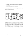
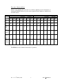
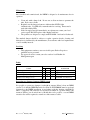
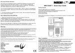
DRIM 24V VFC
Installation and Operating instructions
UNPACKING AND INSPECTION
•
•
If the equipment appears damaged in any way, return it to sales outlet in its
original packaging. No responsibility for damage arising from the use of nonapproved packaging will be accepted.
Ensure all items and accessories specified are present. If not, contact your
sales outlet or local Ruskin Air Management agent.
SAFETY SYMBOLS
The following symbols mean: Danger: electrical shock hazard
Double insulated
Caution: Read these operating instructions fully before use.
Use only as specified by the operating instructions or the intrinsic protection may be
impaired.
SAFETY WARNINGS
Always observe the following safety precautions: •
•
THIS UNIT IS CLASS II CONSTRUCTION!
Ensure power supply links are set corresponding to the desired power supply
voltage before wiring up.
• Always disconnect the equipment from the power supply and ancillary
equipment before moving.
• This equipment is for use indoors in moderate climates only. NEVER use the
equipment in damp or wet conditions.
• Avoid excessive heat, humidity, dust & vibration.
• Do not use where the equipment may be subjected to dripping or splashing
liquids.
• Always use wire with insulation suitable for –5°C to 70°C.
• Ensure that the circuit isolator is easily accessible to allow the unit to be
switched off.
This equipment contains no user-serviceable parts. Refer all repairs to qualified
service personnel.
Rev 1.1 - 23rd February 2008
1
Part No LNNN00325
Overview and set up
Operating Voltage
The DRIM is designed to control and monitor electrically motorised dampers (Spring
return or drive both ways), operating from: • 24 Volts (ac (50Hz or 60Hz) or dc)
Connection must be via a 3A fused (Switched) spur. The actuator (Motor) should be
of class II insulation (double insulated), operating from 24V ac or dc.
Mode of operation
The DRIM may be operated as a single control unit controlling a damper or as two
units controlling a damper enabling the damper to be controlled from both sides of a
wall/bulkhead.
Single unit
The DRIM must be set to the Master mode of operation by setting the link as shown
below and wired in general accordance with drawing AA/F/10158 Sheet 1.
(Supplied): -
Two units
The first unit (connected to the supply) must be set to the Master mode of operation
and the second unit (connected to the first unit and the actuator) set to Slave as shown
below, both units being wired in general accordance with drawing AA/F/10158 Sheet
2. (Supplied): -
Rev 1.1 - 23rd February 2008
2
Part No LNNN00325
Installation
•
•
•
Ensure unit is secured to the wall/surface/bulkhead using suitable 4off 4mm
fastenings and that the mounting surface is able to bear the weight and impact
from operation.
Ensure all cables are routed safely. Avoid sharp bends.
Ensure that only specified cables are used for interconnection of equipment.
The DRIM should be mounted on a flat surface via the four mounting holes located
under the box lid retaining screws. These are spaced at 95mm centres, the overall
dimensions of the DRIM as shown below
+44 (0) 1227 276100
DAMPER RELEASE & INDICATION MODULE
LAMP
TEST
PUSH TO
CLOSE
TWIST TO
OPEN
CLOSED
OPERATED
OPEN
XNNN00588
The DRIM has been designed to be connected directly to the damper actuator (Motor)
leads, the supply being fed via a 3A fused (Switched) spur using a cable of 0.75mm
CSA minimum (maximum 1.5mm CSA). (If the DRIM is required to be mounted in a
position further away than the reach of the actuator (Motor) cables then the DRIM
Extension box (Part No XNNN00666) should be used to extend the connection).
When two DRIMs are used to control a damper, the interconnecting cable must be a
6-core cable of 0.75mm CSA minimum. The Master box must have one of the cable
glands removed and the optional plug (Supplied) installed in its place.
Rev 1.1 - 23rd February 2008
3
Part No LNNN00325
Connections
In this variant, there is no provision for a cable for remote indication. Therefore an
additional hole will have to be drilled in the enclosure (about the centre line on either
of the un-drilled sides) and an additional I.P. 66 cable gland installed. Cables should
be prepared with 75mm of the outer sheath removed and 5mm stripped off of
individual cores. The cables should be inserted into the box through the cable glands
and pulled through sufficiently to enable the wires to be inserted into their appropriate
connections using the connector operating tool as supplied, in accordance with
drawings AA/F/10158 Sheet 1 or 2. (Single unit or two units) Note: - the connections
of the volt free relay contacts are not shown on these drawings.
When all connections have been completed and checked, the cables should be fed
back until the outer sheath can just be seen in the gland. Tighten the gland until it
grips the cable and place the lid and board assembly on to the box, neatly folding the
wires into the bottom of the box. Tighten the lid closure screws in an even manner.
All cable glands must be checked and tightened to ensure a watertight seal on the
cable.
Commissioning & operation
Note: - Allow time for damper to travel to end positions.
Single unit
When set up, installed and connected in accordance with the above instructions (to
drawing AA/F/10158 Sheet 1), power can be applied. Each condition as tabled below
should be tested.
Single unit
Red
Yellow
Operational condition
LED
LED
Lamp Test
Push Button Reset
Push Button Operated
Green
LED
-
Close Relay
Com- ComN/O
N/C
-
Open Relay
Com- ComN/O
N/C
-
The DRIM is now commissioned ready for operation.
Rev 1.1 - 23rd February 2008
4
Part No LNNN00325
Two units – Master and Slave
When set up, installed and connected in accordance with the previous instructions (to
drawing AA/F/10158 Sheet 2), power can be applied. Each condition as tabled below
should be tested.
Lamp
Test Master
Lamp
Test Slave
Push
Button
Reset –
Master
and Slave
Push
Button
Operated
– Master
unit
Push
Button
Operated
– Slave
unit
Push
Button
Operated
– Master
and Slave
unit
Red
LED
Yellow
LED
Master unit
Closed Relay
Green
ComComLED
NO
NC
-
Open Relay
ComComNO
NC
-
-
-
-
-
-
-
Two Units
-
-
-
-
-
-
-
-
Red
LED
Yellow
LED
Green
LED
Slave unit
Closed Relay
ComComNO
NC
-
-
-
-
-
-
-
-
-
-
-
-
-
-
-
-
-
-
-
-
-
The DRIMs are now commissioned ready for operation.
Rev 1.1 - 23rd February 2008
Open Relay
ComComNO
NC
5
Part No LNNN00325
Maintenance
Once installed and commissioned, the DRIM is designed to be maintenance free in
operation.
•
•
•
•
Clean only with a damp cloth. Do not wet or allow moisture to penetrate the
unit. Do not use solvents
Regularly use the lamp test button to indicate that all LEDs light
simultaneously. If a LED fails, return the unit for servicing. It must not be
used with a faulty LED.
If the 3A supply fuse fails immediately on replacement, contact your local
service agent. DO NOT replace with a higher rated fuse.
The products are designed to comply with EN 61010-1 and can be flash tested.
The attached damper should be subject to regular operation checks, cleaning and
lubrication (as instructed by the manufacturer) in accordance with local requirements
or at 12 monthly intervals.
Servicing
•
•
This equipment contains no user-serviceable parts. Refer all repairs to
qualified service personnel.
For approved service contact your sales outlet or local Ruskin Air
Management agent.
Faults
Control
Lamp test pushed
Push button operated Damper closed
Push button operated Damper open
Push button reset Damper closed
LED
Possible fault
Red Yellow Green
Supply failed
Supply failed
Check damper - Possibly jammed
Check ETR – Possibly fused
-
Operating two dampers from one DRIM system
It is possible to operate two dampers (each with an actuator (Motor)) from one DRIM
system. To do this the DRIM Extension box (Part No XNNN00666) must be used and
connected to the DRIM installation in accordance with the drawing AA/F/10158
Sheet 3. (Supplied) The extension box should be mounted in a position where both
actuators (Motors) can be wired into it. Should this not be possible, a second DRIM
extension box will be required to extend one of the actuators cables.
Rev 1.1 - 23rd February 2008
6
Part No LNNN00325
Technical specification
•
•
•
•
•
This equipment is for indoor use and will meet its performance figures within
an ambient temperature range of -5°C to 50°C with maximum relative
humidity of 80%.
Equipment is for operation at installation category II (transient voltages) and
pollution degree II in accordance with IEC 664 at altitudes up to 2000 metres.
Size: - Overall maximum dimensions W 160mm X H 110mm X D 85mm
Weight: - 325g
Supply voltage: Nominal Voltage
24V
Nominal Voltage Range 21.6V to 28.4V
•
•
•
•
Power consumption: - Internal dissipation <6VA – Maximum connected load
not to exceed 30VA
Degree of protection: - I.P. 45 (Cable glands I.P. 55)
EMC: - Not applicable
Low voltage directive: - CE compliant LVD meets EN 61010-1
Manufactured by: Ruskin Air Management (Actionair) Ltd
Joseph Wilson Industrial Estate
South Street
Whitstable
Kent
CT5 3DU
England
Tel: +44(0)1227 276100
Fax: +44(0)1227 264262
Email: [email protected]
Website: www.actionair.co.uk
For technical assistance contact as above or your local Ruskin Air Management agent.
Rev 1.1 - 23rd February 2008
7
Part No LNNN00325